

Digital Cinema Lens
数字电影镜头
CN-E30-105mm T2.8 L S
CN-E30-105mm T2.8 L SP
取扱説明書
OPERATION MANUAL
使用说明书
日 本 語
ENGLISH
ご使用の前に必ずこの取扱説明書をお読みください。
なお、取扱説明書は必要に応じてご覧になれるように大切に保管してください。
Read this operation manual before using the product.
Keep the manual in place for future reference.
在使用本产品之前, 请务必先仔细阅读本使用说明书。
请务必妥善保管好本书, 以便日后能随时查阅(保留备用)。
请在充分理解内容的基础上, 正确使用。
中 文
Appendix
External view
日 本 語 版
日 本 語
商品構成 ............................................................4
各部の名称 .........................................................5
フランジバック調整 ..........................................6
各種アクセサリーの装着 ...................................8
アクセサリー取付け寸法 ...................................9
仕様 .................................................................10
Appendix(巻末付録)
日本語版は、日本国内用の取扱説明書です。
安全にお使いいただくために ...................2
External view(外観図) .
................ apx. 2
日 本 語
3
安全にお使いいただく
ために
製品および取扱説明書に記載されている安全
に関する警告や注意事項は、必ず守ってくだ
さい。
これら危険防止の警告や注意事項にそった取
扱いをしない場合、けがや事故に至る可能性
があります。
この取扱説明書をよく読んで、十分に理解し
た上で本機を正しくご使用ください。
また、この取扱説明書は必要に応じてご覧に
なれるよう大切に保管してください。
この取扱説明書の中では、お客様および他の
人々の安全を守り、事故を未然に防止するた
めの警告文や注意文に以下のシンボルマーク
と言葉を使用しています。
告
警
取扱いを誤った場合に、死亡または重傷を負
う恐れがある警告事項が書かれています。安
全にご使用いただくために、必ずこの警告事
項を守ってください。
意
注
取扱いを誤った場合に、負傷を負う恐れがあ
る注意事項が書かれています。安全にご使用
いただくために、必ずこの注意事項を守って
ください。
1. レンズで太陽や輝度の高い光源をのぞかな
1. 締め付け部は、しっかりと締め付けてくだ
2. 定期的(目安として6ヵ月〜1年ごと)に
3. 修理を行う場合は、キヤノンマーケティン
取扱いについて
告
警
いでください。目に障害を起こす危険があ
ります。
意
注
さい。締め付け部が緩むと、落下してけが
の原因となることがあります。
取付け部に緩みがないか点検してください。
取付け部が緩むと、落下してけがの原因と
なることがあります。
グジャパン(株)、お求めになった代理店、
または直接キヤノンへお問い合わせくださ
い。
ご 注 意
1. レンズに強い衝撃を与えないでください。
ぶつけたり、落としたりすると故障の原因
となることがあります。
2. 急激な温度変化を与えますと、レンズの内
部が曇ってしばらくの間使用できなくなる
ことがありますが、このようなことがない
よう曇り対策処置など十分に配慮してくだ
さい。
ご 注 意
操作する上での注意事項、または推奨事項が
書かれています。
ここに記載されていることを守らないと、製
品が正しく機能しない可能性があります。
また、操作する上で有益な情報も記載されて
います。
2

保守・点検について
ご 注 意
1. レンズの表面についたゴミやほこりは、ブ
ロアーで吹き飛ばすか、柔らかい刷毛で軽
く払ってください。指紋やシミが付いた場
合は、市販のレンズクリーナーを少量浸し
た清浄な柔らかい綿布またはレンズクリー
ニングペーパー(シルボン紙など)で軽く
ふき取ってください。
ゴミなどが付着したままで強くこすると、
レンズ表面に傷が付くことがありますので、
ご注意ください。
2. 使用条件・頻度・環境などにより異なりま
すが、毎年一回程度は保守点検を実施し、
必要な場合にはオーバーホールなどを行っ
てください。
保管について
意
注
1. 保管するときは、必ずレンズキャップ・ダ
ストキャップを付けてください。キャップ
無しの状態で保管した場合、レンズの集光
作用により火災の原因となることがありま
す。
ご 注 意
1. 霧や小雨などで湿気を含んだ場合には、速
やかに乾いた布で水分をふき取り、乾燥剤
(できるだけ新しい乾燥剤を使用)とともに、
ビニール袋に入れて密封し、完全に内部の
湿気を除去してください。
お客様へ
1. お客様の誤った操作に起因する障害につい
ては、当社は、責任を負いかねますのでご
了承ください。
2. 本製品の品質・機能および取扱説明書に関
して、お客様の使用目的に対する適合性・
市場性などについては、一切の保証をいた
しかねます。
また、そこから生じる直接的・間接的損害
に対しても責任を負いかねます。
3. 本製品を使用して得られた結果については、
保証いたしかねます。
4. 本製品の仕様・商品構成・外観図などは、
断りなく変更することがあります。
5. 修理や保守点検、この取扱説明書に記載さ
れていない諸調整などについては、お求め
になった代理店、または下記連絡先までお
問い合わせください。
6. お客様のご都合で、当社に相談なく改造が
行われた製品に対しては、その修理などを
お引き受けできない場合がありますのでご
注意ください。
キヤノン株式会社
〒 146-8501
東京都大田区下丸子 3-30-2
この取扱説明書の著作権はキヤノン株式会社にあります。
この取扱説明書の一部または全部をキヤノン株式会社の承諾書なしに、複写・複製または転載することは、禁
止されています。
キヤノンマーケティングジャパン株式会社
〒 108-8011
東京都港区港南 2-16-6
3
5
商品構成
本製品 CN-E30-105mm T2.8 L には、マウントの形状が異なる 2 つのタイプ(EF マウントの
S タイプと PL マウントの SP タイプ)があります。この取扱説明書では、特記事項がない限
り S タイプのイラストを使用します。
レンズ本体 ..................................................1
ズーム/フォーカスレバー(短) ...............1
ズーム/フォーカスレバー(長) ...............1
取付支柱 ..................................................... 1
レンズキャップ
リファレンスガイド
レンズキャップ ......
ダストキャップ ..........................................1
取扱説明書 ..................................................1
リファレンスガイド ................................... 1
....................................1
取扱説明書
レンズ本体
取付支柱
ズーム/フォーカスレバー(短)
ズーム/フォーカスレバー(長)
* SP タイプ用のダストキャップは形状が異なります。
4
ダストキャップ
*
C
A
N
O
N
Z
O
O
M
L
E
N
S
2.8
4
5.6
8
11
16
22
各部の名称
フォーカスドライブギア
歯数:133
ピッチ:0.8
P.C.D.:106.4mm
操作角:300
°
1.4
1.3
1.2
1.1
1
0.9
0.8
0.7
ズームドライブギア
歯数:111
ピッチ:0.8
P.C.D.:88.8mm
操作角:93.5
°
75
65
60
55
50
45
40
35
32
30
20
10
8
6
5
4
3
2
1.8
1.6
アイリスドライブギア
歯数:111
ピッチ:0.8
P.C.D.:88.8mm
操作角:55
2.8
5.6
11
16
22
°
S
N
E
L
M
O
O
Z
N
O
N
A
C
4
8
調整部
F.B.
カバーリング
支持支柱
マウント(Sタイプ)
EF
取付支柱
ズーム
フォーカスレバー
/
マウント(SPタイプ)
PL
5
7
F.B.
本レンズのフランジバックは下記の手順で調整できます。
あらかじめ、調整作業をしやすい距離 * にコントラストのはっきりした被写体を定めます。
*
推奨被写体距離:1.8 〜 3.7 m
(フランジバック)調整
固定ビス(3 本)
1
固定ビス3個を取り外し
てから、
F.B.
調整部カバー
リングを取り外します。
ご注意:取り外したビスはなくさない
でください。
2
レンズをカメラに取り付
け、
ビス
F.B.
調整リング固定
個を一回転程ゆる
2
F.B. 調整部
カバーリング
固定ビス(2 本)
めます。
意
注
レンズはカメラマウント面に確実に
装着してください。
ご注意:固定ビスをゆるめすぎて
外さないようご注意ください。
°
360
6
3
アイリスリングを回して絞りを開放(
T2.8
)にします。
4
ズームリングを回して望遠(テレ)端にしてから、フォーカス
リングを回して被写体にピントを合わせます。
5
ズームリングを回して広
角(ワイド)端にしてから、
F.B.
被写体にピントを合わせ
ます。
調整リングを回して
調整目盛りを
ご利用ください。
ご注意: この時フォーカスリングを動か
さないようにしてください。
F.B. 調整リング
6
手順4〜5を2、3回繰り返します。
7
F.B.
リングを取り付けます。
調整リングを固定し、反対の手順で
7
F.B.
調整部カバー
9
各種アクセサリーの装着
ロッド径Φ15、Φ19 のシネ用アダプターを使用し、各種アクセサリーをお使いいただくこと
ができます。
(Φ19 のロッドを使用する際は、付属の取付支柱を支持支柱に取り付けてください。)
レンズを装着する際は、必ず支持支柱をご使用ください。レンズサポー
注
意
トにレンズを装着する際、レンズのマウントに無理な力がかからないよ
うご注意ください。
8
1
注
意
S タイプ(EF マウント)レンズは、以下の手順でカメラに装着して
ください。
レンズをカメラのレンズ
マウントにしっかり密着
させて取付けます。
詳細のレンズの取付け方法に関しては
カメラの取扱説明書をご覧ください。
2
レンズサポートに付属の
ネジを使い、レンズの取付
支柱をレンズサポートに
固定します。
レンズサポート
3
レンズとカメラのマウント
どうしがしっかりと密着
するようにして、レンズサ
ポートをロッドにクランプ
します。
9
11
アクセサリー取付け寸法
タイプ(EFマウント)
S
218
146.3
7
75
65
60
55
50
45
40
35
32
30
8
6
5
4
3
2
φ114
8
1.4
1.3
1.2
1.1
1
0.9
0.8
0.7
20
10
1.8
1.6
単位:mm
5.5
77.2
6
44.9
S
N
E
L
M
O
O
Z
N
O
N
A
C
2.8
4
5.6
8
11
16
1
0
22
0
0
1
6
3
9
125
68
UNC1/4-20
タイプ(PLマウント)
SP
8 138.3
1.4
1.3
1.2
1.1
1
0.9
φ114
0.8
0.7
UNC1/4-20
20
10
1.8
1.6
12
210
8
6
5
4
3
2
12
111.1
27
UNC3/8-16
69.2
7
6
36.9
11.8
φ17
2±0.02
75
65
60
55
50
45
40
35
32
30
S
N
E
L
M
O
O
Z
N
O
N
A
C
2.8
4
5.6
8
11
16
1
22
0
0
0
1
6
3
9
125
68
103.1
27
UNC3/8-16
φ17
ギア仕様
フォーカスドライブギア ズームドライブギア アイリスドライブギア
歯数 133 111 111
モジュール 0.8 0.8 0.8
P.C.D. 106.4mm 88.8mm 88.8mm
操作角 300
°
10
93.5
°
55
°
仕様
CN-E30-105mm T2.8 L S CN-E30-105mm T2.8 L SP
マウントタイプ キヤノン EF マウント PL マウント
焦点距離 30 〜 105 mm
T ナンバー T2.8(f=30 〜 105)
絞り羽根枚数 11
像面
Super 35mm
イメージサークル/
水平 x 垂直(1.78:1)
広角端画角(水平/垂直) 43.6° / 25.4
望遠端画角(水平/垂直) 13.0° / 7.4
像面
EOS C300
イメージサークル/
水平 x 垂直(1.78:1)
広角端画角(水平/垂直) 44.6° / 25.9
望遠端画角(水平/垂直) 13.4° / 7.5
像面
EOS C500
イメージサークル/
水平 x 垂直(1.9:1)
広角端画角(水平/垂直) 47.2°
望
遠端画角(水平/垂直) 14.2° / 7.5
最短撮影距離(M.O.D.) 0.6 m(イメージセンサーから)
Super 35mm
M.O.D. 時の
被写体範囲
(横 x 縦)
フォーカス操作角 300
ズーム操作角 93.5
ギアモジュール 0.8
フロント径
全長 218 mm 210 mm
質量 2.2 kg
*本製品はΦ15、Φ19 の各種シネ用アクセサリーに対応しています。
* 本製品は、センサーサイズが Super 35mm 相当および APS-C のカメラに対応していますが、
35mm フルサイズおよび APS-H のカメラには対応していません。
EOS C300
EOS C500
Φ
27.5 mm /
24.0 x 13.5 mm
°
°
Φ
28.2 mm /
24.6 x 13.8 mm
°
°
Φ
29.6 mm /
26.2 x 13.8 mm
/ 25.9
32.3 x 18.2 cm(広角端)
9.3 x 5.2 cm(望遠端)
33.1 x 18.6 cm(広角端)
9.6 x 5.4 cm(望遠端)
35.3 x 18.6 cm(広角端)
10.2 x 5.4 cm(望遠端)
Φ
114 mm
°
°
°
°
11

参考情報
本レンズは動画撮影用フルマニュアルレンズです。
• 本レンズは映画制作を主眼に開発され、映画用に一般的なカラーバランスを持っています。
静止画撮影を基本とする EF レンズと比較すると暖色味を帯びた色再現になっていますので、
両レンズを併用する際は、必要に応じカラーバランスの調整(ホワイトバランスの取直しなど)
を実施してください。
• 絞り開放付近および近距離の被写体では、一般に被写界深度が浅く、ピントの合う範囲が極め
てせまくなります。また、焦点距離が長いレンズほどこの傾向は顕著になります。撮影にあたっ
ては、ファインダーの拡大モード等で合焦状態を慎重に確認し、十分なテスト撮影を行った上
でフォーカス操作を行ってください。
マウントレンズ限定)
(EF
• 本レンズの絞りリング上には T 値を表示しています。一方、このレンズからカメラへの絞り情
報は、従来の E F レンズとの併用を考慮して F 値を使用
絞りリング上の表示と異なる値(F 値)が表示されます。
• レンズ焦点距離情報のカメラ側の表示は、小数点以下が切り捨てられて表示されます。
しているため、カメラ側ではレンズの
12

ENGLISH
ENGLISH
GENERAL SAFETY INFORMATION ......4
Product Conguration .......................................6
Names of Parts .................................................7
F.B. (Back Focus) Adjustment ...........................8
Available Accessories .....................................10
Dimensions of Parts ........................................ 11
Specications .................................................. 12
Appendix
External view ................................. apx. 2
The English version is the operation manual for counties other than Japan.

3
This device complies with Part 15 of the FCC Rules. Operation is subject to the following two
conditions: (1) This device may not cause harmful interference, and (2) this device must accept
any interference received, including interference that may cause undesired operation.
Note: This equipment has been tested and found to comply with the limits for a Class B digital
device, pursuant to Part 15 of the FCC Rules. These limits are designed to provide reasonable
protection against harmful interference in a residential installation. This equipment generates,
uses and can radiate radio frequency energy and, if not installed and used in accordance with
the instructions, may cause harmful interference to radio communications. However, there is
no guarantee that interference will not occur in a particular installation. If this equipment does
ENGLISH
cause harmful interference to radio or television reception, which can be determined by turning
the equipment off and on, the user is encouraged to try to correct the interference by one or
more of the following measures:
-- Reorient or relocate the receiving antenna.
-- Increase the separation between the equipment and receiver.
-- Connect the equipment into an outlet on a circuit different from that to which the receiver is
connected.
-- Consult the dealer or an experienced radio/TV technician for help.
Do not make any changes or modications to the equipment unless otherwise specied in
the manual. If such changes or modications should be made, you could be required to stop
operation of the equipment.
FCC REGULATIONS
Canadian Radio Interference Regulations
CAN ICES-3(B)/NMB-3(B)
2

European Union (and EEA) only.
This symbol indicates that this product is not to be disposed of with your
household waste, according to the WEEE Directive (2002/96/EC) and your
national law. This product should be handed over to a designated collection
point, e.g., on an authorized one-for-one basis when you buy a new similar
product or to an authorized collection site for recycling waste electrical and
electronic equipment (EEE). Improper handling of this type of waste could
have a possible negative impact on the environment and human health due to
potentially hazardous substances that are generally associated with EEE. At
the same time, your cooperation in the correct disposal of this product will contribute to the
effective usage of natural resources. For more information about where you can drop off your
waste equipment for recycling, please contact your local city ofce, waste authority, approved
WEEE scheme or your household waste disposal service.
Your cooperation in the correct disposal of this product will contribute to the effective usage
of natural resources and will avoid incurring administrative sanctions according to art. 50 and
following of Italian legislative decree 22/97.
For more information regarding return and recycling of WEEE products, please visit
www.canon-europe.com/environment.
(EEA: Norway, Iceland and Liechtenstein)
3

5
GENERAL SAFETY
INFORMATION
The safety warnings and cautions provided on
the product or in this operation manual must
be observed.
Failure to observe these warnings and
cautions provided to guard against hazards
may result in injury or accident.
Read this operation manual carefully to
familiarize yourself with its contents and
ensure that you can operate the product
properly.
Also, store this manual in a safe place where
it can easily be referenced whenever required.
This operation manual uses the following
symbols and terms to identify hazards to
protect you and others by preventing the
occurrence of accidents.
WARNING
This indicates a potentially hazardous
situation which, if not heeded, may result in
death or serious injury to you or others. Be
sure to heed all warning notices to ensure
safe operation at all times.
HANDLING THE
PRODUCT
WARNING
1. Do not stare at the sun or other source of
high-intensity light through the lens. Doing
so could injure your eyes.
CAUTION
1. Make sure all mountings are tightened
securely. If any of these mountings
becomes loose, the lens may fall, possibly
causing injury.
2. Inspect all mountings periodically (about
every 6 months to 1 year) to make sure
they are securely tightened, and tighten
any loose parts. Otherwise, the lens may
fall, possibly causing injury.
3. If it becomes necessary to repair this
product, or to perform any operations or
adjustments not mentioned in this operation
manual, contact Canon’s representative or
the dealer who originally supplied the lens.
NOTE
CAUTION
Indicates hazardous situations which, if not
heeded, may result in minor or moderate
injury to you or other persons, or damage to
your property.
NOTE
Emphasizes essential information which, if not
heeded, may render the product unworkable
or cause it to function improperly.
Also, provides helpful information for
operation.
1. Protect the lens from strong impacts or
shocks. Striking or dropping the lens may
result in a malfunction.
2. Do not bring the lens, kept in a very cold
ambient temperature, into a warm room,
because the lens may fog on the inside or
condensation may occur.
In these cases, the lens cannot be used
until these problems clear.
If the lens must be used under such
conditions, countermeasures are
recommended.
4

MAINTENANCE AND
INSPECTION
NOTE
1. Gently blow or brush away dust or dirt on
the lens surface using a lens blower or a
soft lens brush. Remove any ngerprints or
other stains with a soft clean cotton cloth
moistened with commercially available lens
cleaning uid or lens cleaning paper.
Be careful not to rub dust across the lens,
as the lens surface may be scratched.
2. A periodic inspection about once a year is
recommended.
The inspection and maintenance interval
depends on the operating conditions, the
frequency of use, and the environment. If
required, overhaul the lens.
STORAGE
CAUTION
1. Always attach the lens cap (or hood
cap) and the dust cap before storing the
lens. Storing the lens without these caps
attached may present a re hazard. (Very
bright light, such as sunlight, may be
focused by the lens and cause a re.)
NOTE
1. If the lens becomes damp because of
use in fog, mist, or drizzle, wipe off the
moisture with a soft dry cloth and seal the
lens together with an effective desiccant
in a vinyl bag to remove moisture that has
entered the interior.
TO THE CUSTOMER
1. Canon shall bear no responsibility for
damage resulting from improper operation
of this product by the customer.
2. Canon shall make no guarantees about
the product quality, functions, or operation
manual and its marketability and suitability
for the customer’s purpose.
Moreover, Canon shall bear no
responsibility for any damage, direct or
incidental, that results from usage for the
customer’s purpose.
3. Canon shall make no guarantees about the
results obtained using this product.
4. The product specications, conguration,
and appearance are subject to change
without prior notice.
5. For further information on repairs,
maintenance, or adjustments not
mentioned in this operation manual,
contact your Canon dealer or your Canon
sales representative.
6. Note that Canon may be unable to
undertake servicing or repair of a product
if it is modied without consulting Canon or
your Canon sales representative.
CANON INC.
30-2, Shimomaruko 3-chome, Ohta-ku, Tokyo 146-8501, Japan
Canon Europe Ltd
3 The Square, Stockley Park, Uxbridge, Middlesex, UB11 1ET UK
All rights reserved. No part of this operation manual may be reproduced or copied in any form or by any
means without the written permission of Canon Inc.
5

7
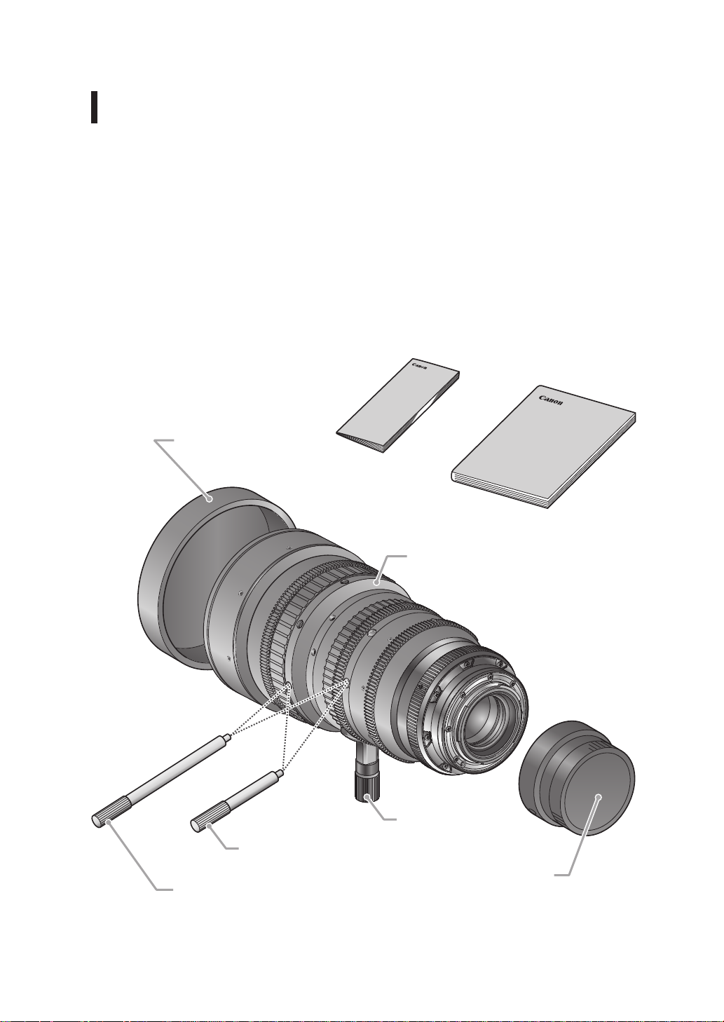
Product Conguration
Two types of the CN-E30-105mm T2.8 L are available for the positive lock mount (S type)
and the Canon EF mount (SP type). Figures in this manual are for the S type lens unless
otherwise mentioned.
Lens body ...................................................1
Zoom/focus lever (short) ............................1
Zoom/focus lever (long) ..............................1
Attachment holder ......................................1
Lens cap
Reference Guide
Lens cap .....................................................1
Rear lens cap .............................................1
Operation Manual .......................................1
Reference Guide ........................................1
Operation Manual
Lens body
Attachment holder
Zoom/focus lever (short)
Rear lens cap*
Zoom/focus lever (long)
* The shape of the rear lens cap for the SP type differs from the gure above.
6

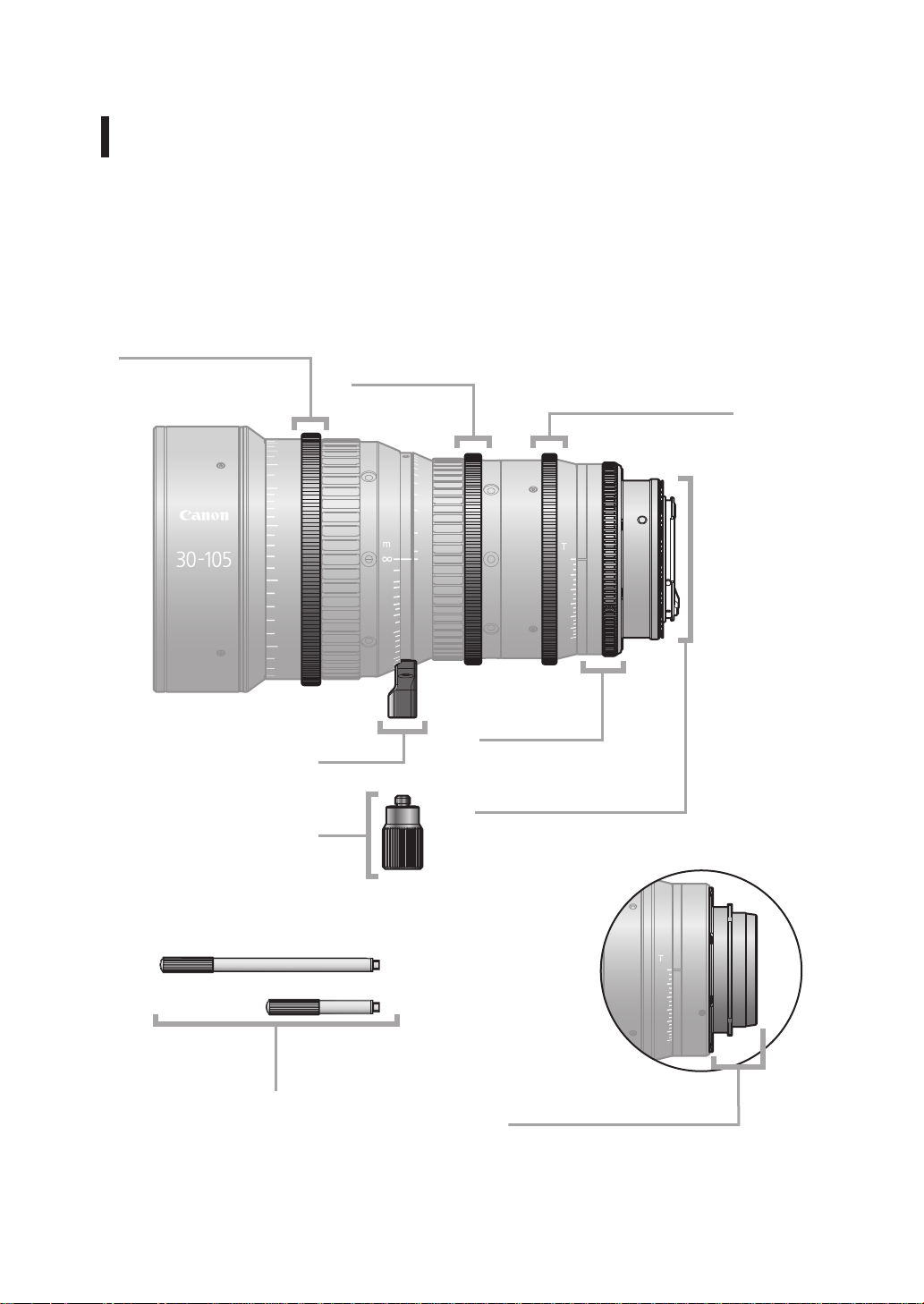
Names of Parts
C
A
N
O
N
Z
O
O
M
L
E
N
S
2.8
4
5.6
8
11
16
22
Focus drive gear
Number of teeth: 133
Pitch: 0.8 metric module
P.C.D.: 106.4 mm
Angular rotation: 300°
1.4
1.3
1.2
1.1
1
0.9
0.8
0.7
Zoom drive gear
Number of teeth: 111
Pitch: 0.8 metric module
P.C.D.: 88.8 mm
Angular rotation: 93.5°
75
65
60
55
50
45
40
35
32
30
20
10
8
6
5
4
3
2
1.8
1.6
Iris drive gear
Number of teeth: 111
Pitch: 0.8 metric module
P.C.D.: 88.8 mm
Angular rotation: 55°
S
N
E
L
M
O
O
Z
N
O
N
A
C
2.8
4
5.6
8
11
16
22
F.B. adjuster
cover
Lens holder
EF mount (S type)
Attachment holder
Zoom/focus levers
7
PL mount (SP type)

9
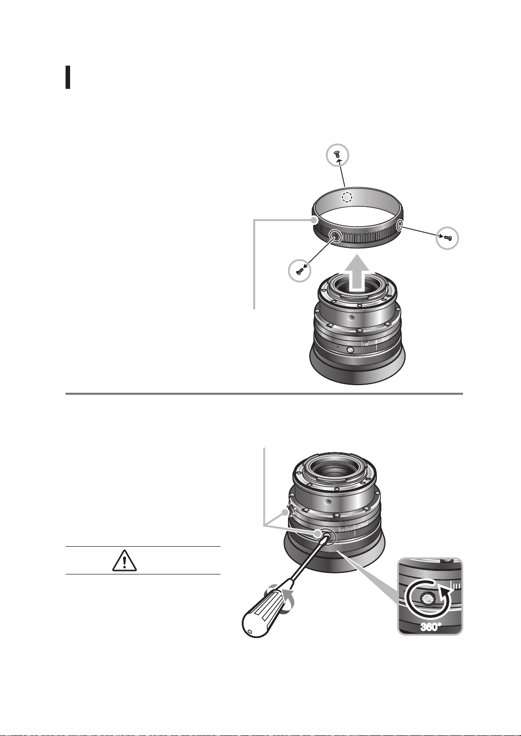
F.B. (Back Focus) Adjustment
F.B. (back focus) of this lens can be adjusted in the following procedures.
Before starting, select an object with sharp contrast at a distance* that facilitates the
adjustment work.
* Recommended object distance range: 1.8 to 3.7 m.
Screws x 3
1
Remove three screws
and remove the F.B.
adjuster cover as in the
right gure.
Note: Be sure to keep the
screws for later reattachment.
F.B. adjuster
cover
2
Mount the lens on the
camera and turn two
F.B. adjuster screws
counterclockwise one
revolution as in the right
gure.
CAUTION
Be sure to securely mount the lens on
the camera mount.
Note: Be sure not to remove
the screws.
Screws x 2
8
360 degrees

3
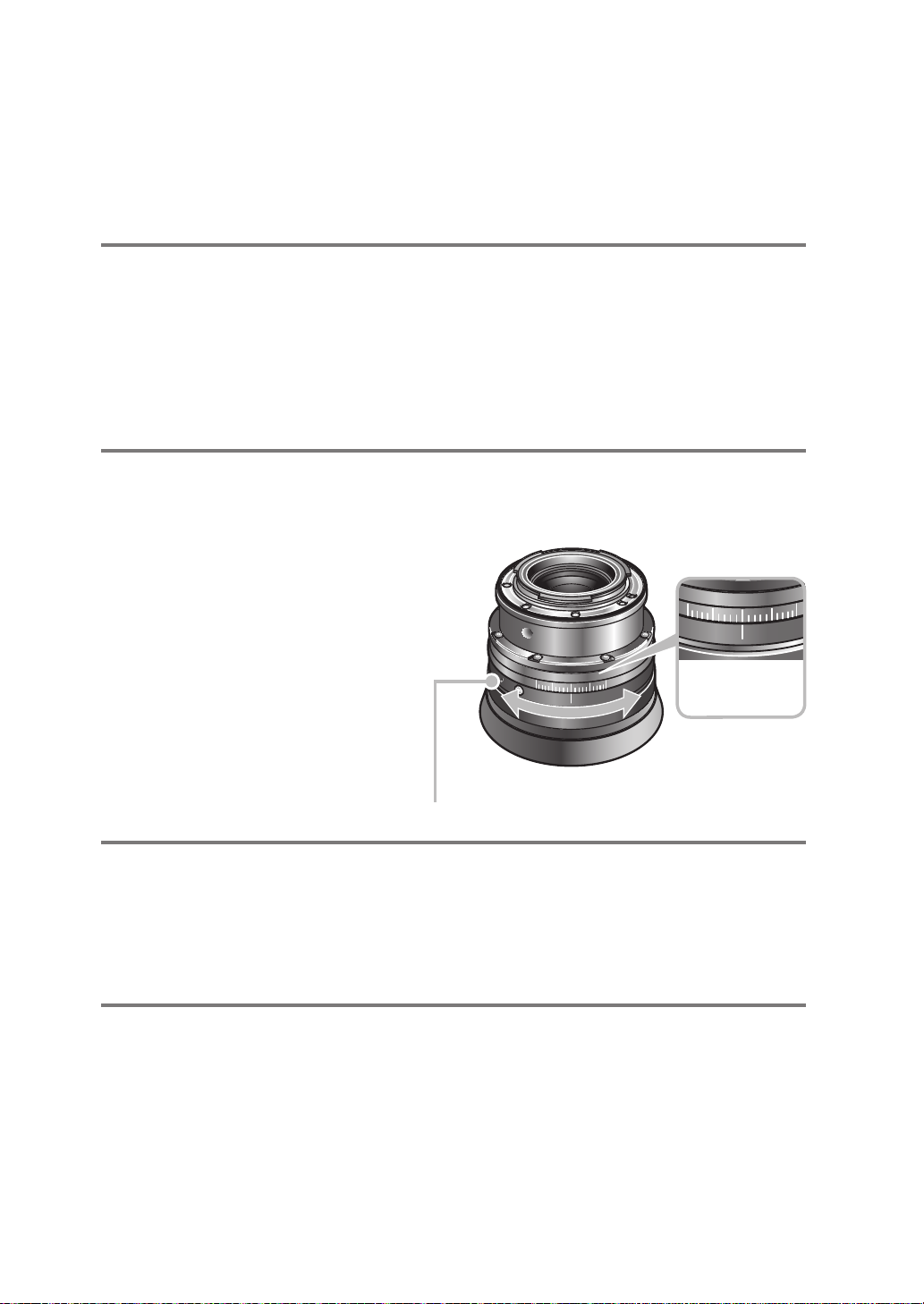
Turn the iris ring to set the iris to fully open (T2.8).
4
Turn the zoom ring to set the lens to the telephoto end,
then turn the focus ring to bring the object into focus.
5
Turn the zoom ring to
set the lens to the wide
angle end, then turn the
F.B. adjuster to bring the
object into focus.
Note: Be sure not to move the focus
ring at this time.
F.B. adjuster
Use the index
mark and
adjuster scale
for back focus
adjustment.
6
Repeat steps 4 and 5 two or three times.
7
Secure the F.B. adjuster and reattach the F.B. adjuster
cover following the reverse procedure.
9

11
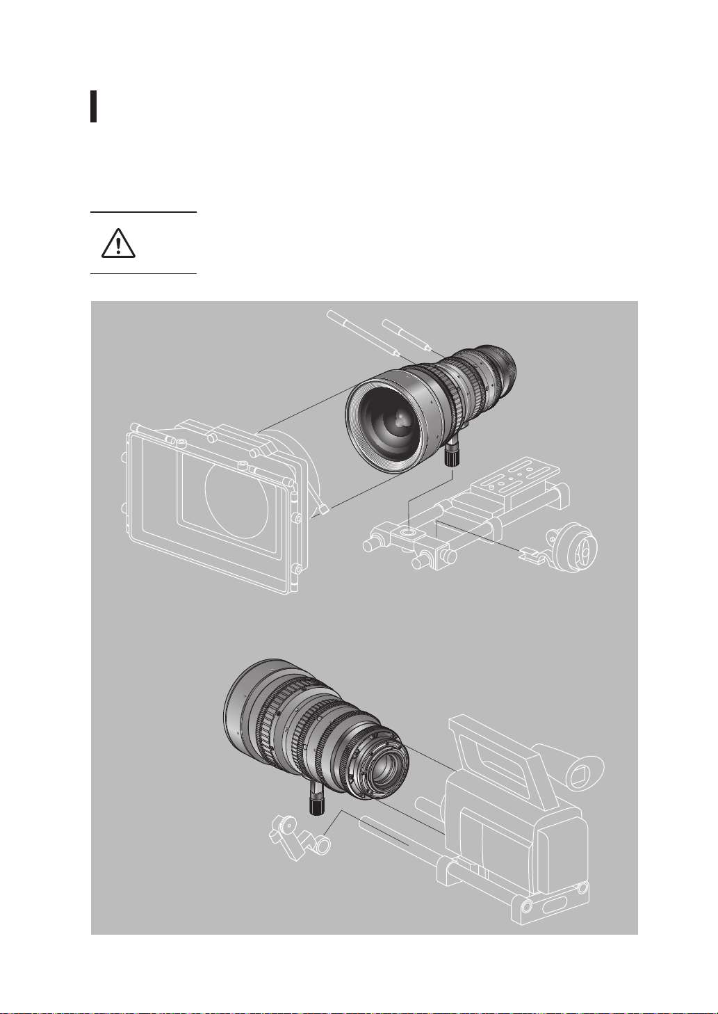
Available accessories
A variety of professional camera accessories are available using Φ15 mm and Φ19 mm rod
adaptors.
(When using a Φ19 rod, attach the supplied attachment holder to the lens holder.)
Be sure to use the lens holder when mounting the lens on a
CAUTION
camera. Be sure to avoid applying excessive weight to the lens
mount when the lens is mounted on a lens support.
10

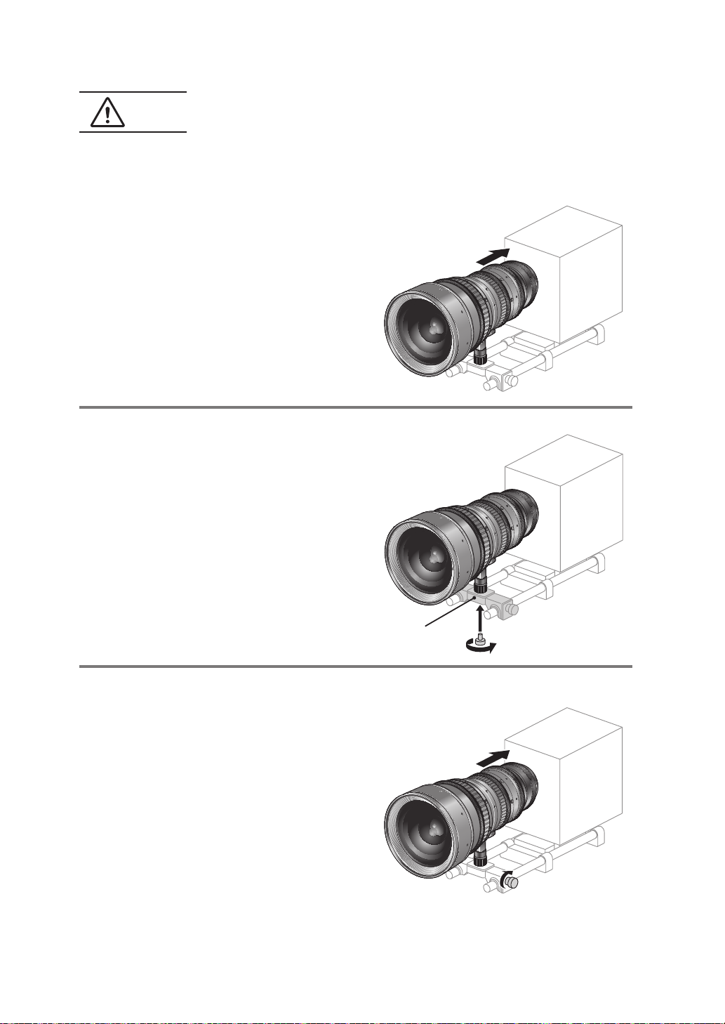
CAUTION
Mount the S type (EF mount) lens to the camera by following
the steps below.
1
Attach the lens to the
camera tightly so that
both mounting surfaces
are in complete contact.
Refer to the operation manual for the
respective camera for the detailed
information.
2
Secure the attachment
holder on the lens
support using the
clamping screw supplied
with the lens support.
3
Push the lens toward
the camera until both
mounting surfaces are
in complete contact and
clamp the lens support to
the rods.
Lens support
11

13
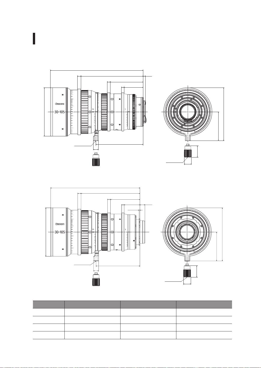
Dimensions of parts
S type (EF mount)
218
8
1.4
1.3
φ114
1.2
1.1
1
0.9
0.8
0.7
75
65
60
55
50
45
40
35
32
30
20
10
8
6
5
4
3
2
1.8
1.6
146.3
7
Unit: mm
5.5
77.2
6
44.9
S
N
E
L
M
O
O
Z
N
O
N
A
C
2.8
4
5.6
8
11
16
1
0
22
0
0
1
6
3
9
125
68
UNC1/4-20
SP type (PL mount)
8 138.3
1.4
1.3
1.2
1.1
1
0.9
φ114
0.8
0.7
UNC1/4-20
210
20
10
1.8
1.6
111.1
12
UNC3/8-16
69.2
7
6
36.9
11.8
27
φ17
2±0.02
75
65
60
55
50
45
40
35
32
30
8
6
5
4
3
2
S
N
E
L
M
O
O
Z
N
O
N
A
C
2.8
4
5.6
8
11
16
1
22
0
0
0
1
6
3
9
125
68
103.1
12
UNC3/8-16
27
φ17
Spur gear specications
Focus drive gear Zoom drive gear Iris drive gear
Number of teeth 133 111 111
Module 0.8 metric module 0.8 metric module 0.8 metric module
P.C.D. 106.4 mm 88.8 mm 88.8 mm
Angular rotation 300 degrees 93.5 degrees 55 degrees
12

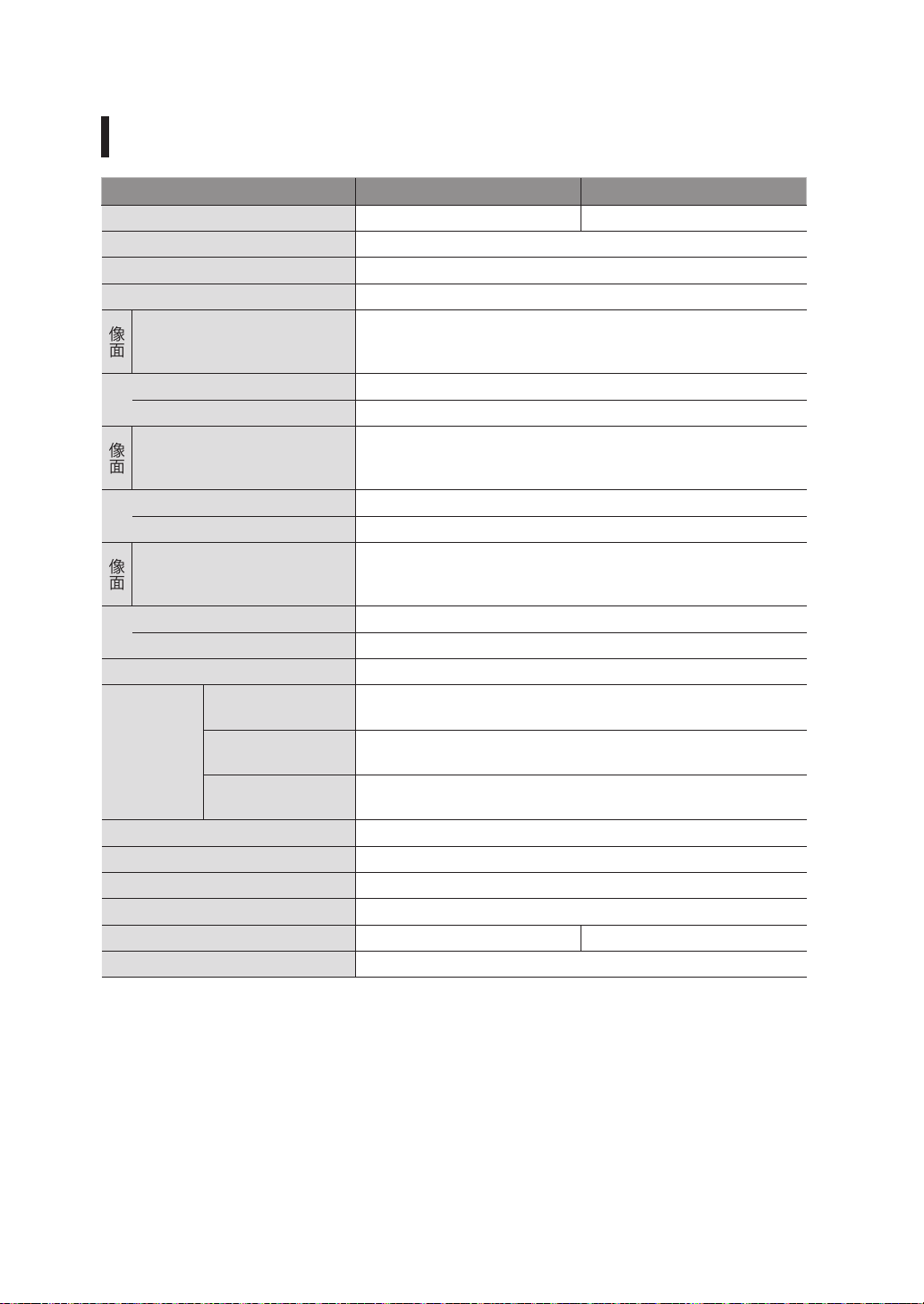
Specications
CN-E30-105mm T2.8 L S CN-E30-105mm T2.8 L SP
Lens Mount Canon EF PL
Focal Length 30 to 105 mm
Maximum T-stop T2.8 (f = 30 to 105)
Iris Blades 11 pieces
Super 35mm
Coverage
Image Circle / H x V
(1.78:1)
Angular Field of View
(H / V) at wide angle end
Angular Field of View
(H / V) at telephoto end
EOS C300
Coverage
Image Circle / H x V
(1.78:1)
Angular Field of View
(H / V) at wide angle end
Angular Field of View
(H / V) at telephoto end
EOS C500
Coverage
Image Circle / H x V
(1.9:1)
Angular Field of View
(H / V) at wide angle end
Angular Field of View
(H / V) at telephoto end
Minimum Object Distance
(M.O.D.)
Super 35mm
Object
Dimensions at
EOS C300
M.O.D.
EOS C500
0.6 m / (from the image sensor)
32.3 x 18.2 cm at wide angle end
9.3 x 5.2 cm at telephoto end
33.1 x 18.6 cm at wide angle end
9.6 x 5.4 cm at telephoto end
35.3 x 18.6 cm at wide angle end
10.2 x 5.4 cm at telephoto end
Focus Angular Rotation 300 degrees
Zoom Angular Rotation 93.5 degrees
Spur Gear Module 0.8 metric module
Front Diameter Φ114 mm
Length 218 mm 210 mm
Weight 2.2 kg
* A variety of professional camera accessories compatible with the Φ15 mm and Φ19 mm rod
system can be used with this lens.
* This lens is compatible with EOS cameras that have a Super 35mm or equivalent sensor, or
an APS-C image sensor. The lens is not compatible with cameras that have a 35-mm full-size
sensor or an APS-H sensor.
Φ27.5 mm /
24.0 x 13.5 mm
43.6 / 25.4 degrees
13.0 / 7.4 degrees
Φ28.2 mm /
24.6 x 13.8 mm
44.6 / 25.9 degrees
13.4 / 7.5 degrees
Φ29.6 mm /
26.2 x 13.8 mm
47.2 / 25.9 degrees
14.2 / 7.5 degrees
13

Reference Information
This lens is a full manual lens for shooting movies.
• This lens is developed primarily for movie production, and have a color balance typical for
movies. This means that the color reproduction is warmer than that of EF lenses which
are basically used to shoot still images. Therefore, when using both types of lens together,
adjust the color balance (redo the white balance etc.) as necessary.
• In general, the depth of eld becomes shallow and the focusing range becomes extremely
narrow near the widest aperture and when shooting a subject at close range. In addition,
this tendency increases for lenses with longer focal lengths. When shooting images,
carefully check the focusing condition using the zoom mode of the nder or other means,
and shoot a sufcient number of test images before performing focus operations.
(for EF mount Lens only)
• The T-numbers of this lens are indicated on the iris ring of the lens. On the other hand,
the iris information from this lens to the camera uses the F-number in consideration of use
together with conventional EF lenses. Therefore, the camera side displays a different value
(F-number) from the indication on the iris ring of the lens.
• Information of the focal length displayed on the camera side omits the gures below the
decimal point.
14

中文
产品配置 ........................................................ 4
各部位名称 ..................................................... 5
F.B.(后焦)调整 ............................................. 6
可以利用的附件 .............................................. 8
各部位尺寸 ................................................... 10
规格 .......................................................
索引.
Appendix(附录)
中文版使用说明书用于日本以外的国家。
安全使用须知 ........................................2
...... 11
............................................................. 11
Depth-of-field(景深) ................. apx. 2
External view(外部视图) ........ apx. 34
中 文

中 文
3
安全使用须知
请务必严格遵守产品以及使用说明书中记
载的有关安全使用警告和注意事项。
操作时不严格遵守这些防止危险的警告和
注意事项,则有可能导致发生受伤或事故。
请认真阅读和充分理解本使用说明书的内
容,正确使用本产品。
请妥善保管本使用说明书,以备需要时能
够随时予以查阅。
为能确保顾客和他人的安全,有效地杜绝
事故发生,我们在本使用说明书的警告事
项和注意事项中采用了以下标记符号和表
述。
警 告
记载了有关错误使用操作将有可能导致死
亡或重伤之危险的警告事项。为了能够确
保安全使用,请务必严格遵守这些警告事
项。
注 意
记载了有关错误操作使用将有可能导致人
体受伤之危险的注意事项。为能确保安全
使用,请务必严格遵守这些注意事项。
关于操作使用
警 告
1. 请勿通过镜头直视太阳或高亮度的光
源,否则有可能造成眼睛受损。
注 意
1. 请牢固地拧紧安装部位。安装部位松弛,
脱落,有可能导致操作人员受伤。
2. 请定期(大约每 6 个月~ 1 年)检查安
装部位是否松弛。安装部位松弛,脱落,
有可能导致操作人员受伤。
3. 需修理时,请在购买镜头的代理店或佳
能公司的维修服务指导下进行修理。
须 知
1. 请勿向镜头施加剧烈的冲击。碰撞,摔
落都有可能导致故障发生。
2. 温度发生急剧变化时,镜头会因其内部
雾气模糊而暂时无法使用,请采取妥善
的防雾措施,避免此类情况发生。
须 知
描述了涉及操作方面的注意事项或建议采
纳事项。不严格遵守这些记载内容,则将
可能使产品不能正常地发挥其功能作用。
同时,还记载了有关操作方面的有用信息。
2

关于保养与检修
须 知
1. 镜头表面附着有污垢或灰尘时,请使用
吹风机将其清除,或使用柔软毛刷轻轻
拂拭。发现指纹或污点附着于镜头表面
时,请使用干净柔软的棉布含浸少量的
市场上销售的镜头专用清洁剂,或使用
镜头专用清洁纸(皱纹纸等)轻轻地擦拭。
请注意,用力擦拭附着污垢的镜头,有
可能损伤镜头表面。
2. 检修保养的时间会因使用条件,次数,
环境等不同而异,但至少应毎年进行一
次检修保养,必要时可进行彻底的拆卸
检修。
关于保管
注 意
1. 保管时,请务必盖好镜头盖(或遮光盖),
防尘盖。如果在未盖好盖子的状态下加
以保管,则有可能因镜头的聚光作用而
导致发生火灾。
须 知
1. 如发现因雾气或小雨等而产生湿气时,
应立即用干布擦拭水分,然后将其与干
燥剂(尽量使用新的干燥剂)一起装入
密封的塑料袋内,以便将其内部的湿气
全部清除。
致顾客
1. 请注意,凡属于因顾客自己的错误操作
而导致发生的故障,本公司将一概不承
担任何责任。
2. 凡涉及本产品的质量,功能以及使用说
明书有关,本公司对于是否符合顾客使
用目的之适应性和市场性等,不做任何
承诺保证。
而且,对于由此而产生的直接或间接损
失,本公司将一概不承担任何责任。
3. 对于使用本产品而产生的结果,本公司
不做任何承诺保证。
4. 本公司有可能更改本产品的规格,产品
结构,外观等,恕不事先逐一通知。
5. 凡属于修理,保养检查或进行本使用说
明书中未记载的各项调整等时,请与维修
服务代理店或直接与佳能公司联系咨询。
6. 请注意,凡属于顾客因自己的具体情
况,未与本公司商洽而擅自改装后的产
品,本公司将有可能不承接有关方面的
修理。
进口商 :
佳能(中国)有限公司
北京市东城区金宝街 89 号 金宝大厦 15 层
邮编 100005
电话 :+86(0)10-8513-9999
传真 :+86(0)10-8513-9915
本使用说明书的著作权归属于佳能公司所有。
未征得佳能公司书面同意的情况下,严禁擅自复印,复制或转载本使用说明书的全部或一部分
内容。
3

5
产品配置
可以利用两种类型的CN-E30-105mm T2.8 L,一种用于阿莱PL基座(S型),另一种用于佳能
EF基座(SP型)。除非另外指出,本说明书中均采用S型镜头的图示。
镜头主体 ................................................. 1
变焦/聚焦杆(短) ................................... 1
变焦/聚焦杆(长) ................................... 1
安装支柱 ................................................. 1
镜头盖
镜头盖 ..................................................... 1
镜头后盖 ...............................................
使用说明书
参考指南 ................................................. 1
参考指南
.............................................. 1
使用说明书
镜头主体
.. 1
变焦/聚焦杆(短)
变焦/聚焦杆(长)
* SP型用的镜头后盖的形状与上图不同。
安装支柱
镜头后盖*
4

各部位名称
C
A
N
O
N
Z
O
O
M
L
E
N
S
2.8
4
5.6
8
11
16
22
聚焦驱动齿轮
齿数 :133
齿距 :0.8 米制模数
P.C.D. : 106.4 mm
角旋转 :300°
变焦驱动齿轮
齿数 :111
齿距 :0.8 米制模数
P.C.D. : 88.8 mm
角旋转 :93.5°
1.4
1.3
1.2
1.1
1
0.9
0.8
0.7
75
65
60
55
50
45
40
35
32
30
20
10
8
6
5
4
3
2
1.8
1.6
光圈驱动齿轮
齿数 :111
齿距 :0.8 米制模数
P.C.D. : 88.8 mm
角旋转 :55°
S
N
E
L
M
O
O
Z
N
O
N
A
C
2.8
4
5.6
8
11
16
22
F.B.调节器盖
镜头支柱
EF基座(S型)
安装支柱
变焦/聚焦杆
5
PL基座(SP型)

7
F.B.(后焦)调整
能够以下列的步骤调整本镜头的后焦
预先将对比度清晰的拍摄景物定位于容易进行调整操作的距离*。
* 推荐物距范围:1.8 至3.7 米。
1
卸下 3 个螺丝后,卸下后
焦调节器盖。
注: 请务必保留螺丝以备之后重新
安装。
后焦调节器盖
螺丝 x 3
2
将镜头安装在摄像机上,
然后将两个后焦调节环螺
丝逆时针转动一圈。
注意
确保将镜头牢固地安装在摄像机基
座上。
注:请注意不要卸下螺丝。
螺丝 x 2
6
360度

3
转动光圈环将光阑设为开放(T2.8)。
4
将变焦环转动到长焦端,然后转动聚焦环对拍摄景物聚焦。
5
将变焦环转动到广角端,
然后转动后焦调节环对拍
摄景物聚焦。
注:此时请注意不要移动聚焦环。
使用指标点和
调节器标度进
行后焦调节。
后焦调节环
6
重复两三次步骤 4 ~ 5 的操作。
7
固定后焦调节环,以相反步骤安装后焦调节器盖。
7

9
可以利用的附件
通过使用Φ15毫米和Φ19毫米支撑棒适配器,可以利用多种专业摄像机附件。
(使用Φ19毫米的支撑棒时,请将附带的安装支柱安装在镜头支柱上。)
注意
将镜头安装在摄像机上时,请务必使用镜头支柱。当镜头安装在
镜头支架上时,请注意不要对镜头基座施加过度的重量。
8

注意
请按照如下步骤将S型(EF基座)镜头安装到摄像机。
1
请将镜头紧贴摄像机的镜头
基座安装在其上。
有关镜头的详细安装方法,请参阅摄像
机的使用说明书。
2
使用随镜头支架附带的固定
螺丝,将安装支柱固定在镜
头支架上。
3
朝摄像机方向推动镜头,直
到两侧的基座表面完全接触,
然后将镜头支架夹紧在支撑
棒上。
镜头支架
9

11
各部位尺寸
S型(EF基座)
φ114
单位:mm
218
8
1.4
1.3
1.2
1.1
1
0.9
0.8
0.7
20
10
1.8
1.6
146.3
77.2
7
6
44.9
75
65
60
55
50
45
40
35
32
30
8
6
5
4
3
2
2.8
4
5.6
8
11
16
1
0
22
0
0
1
6
3
9
5.5
S
N
E
L
M
O
O
Z
N
O
N
A
C
125
68
SP型(PL基座)
φ114
UNC1/4-20
12
210
8 138.3
1.4
1.3
1.2
1.1
1
0.9
0.8
0.7
75
65
60
55
50
45
40
35
32
30
20
10
8
6
5
4
3
2
1.8
1.6
UNC1/4-20
12
111.1
27
UNC3/8-16
69.2
7
6
36.9
11.8
φ17
2±0.02
S
N
E
L
M
O
O
Z
N
O
N
A
C
2.8
4
5.6
8
11
16
1
22
0
0
0
1
6
3
9
125
68
103.1
27
UNC3/8-16
φ17
直齿轮规格
聚焦驱动齿轮 变焦驱动齿轮 光圈驱动齿轮
齿数 133 111 111
模块 0.8米制模数 0.8米制模数 0.8米制模数
P.C.D. 106.4 mm 88.8 mm 88.8 mm
角旋转 300度 93.5度 55度
10

规格
CN-E30-105mm T2.8 L S CN-E30-105mm T2.8 L SP
镜头基座 佳能EF PL
焦点距离 30 至 105 mm
最大光圈系数 T2.8 (f = 30 至 105)
光圈叶片 11片
覆盖范围
覆盖范围
覆盖范围
至近距离 0.6 m /(自图像感应器)
至近拍摄范围
聚焦角旋转 300度
变焦角旋转 93.5度
直齿轮模块 0.8米制模数
前端直径 Φ114 mm
长度 218 mm 210 mm
重量 2.2 kg
* 可以与本镜头配合使用多种兼容Φ15 mm和Φ19 mm支撑棒系统的专业摄像机附件。
* 本镜头兼容具有Super 35mm或同等感应器、或APS-C图像感应器的EOS相机。本镜头不
兼容具有35-mm全尺寸感应器或APS-H感应器的相机。
Super 35mm
成像圈 / H × V (1.78:1)
广角端的成像角度 (H / V) 43.6 / 25.4度
长焦端的成像角度 (H / V) 13.0 / 7.4度
EOS C300
成像圈 / H × V (1.78:1)
广角端的成像角度 (H / V) 44.6 / 25.9度
长焦端的成像角度 (H / V) 13.4 / 7.5度
EOS C500
成像圈 / H × V (1.9:1)
广角端的成像角度 (H / V)
长焦端的成像角度 (H / V) 14.2 / 7.5度
Super 35mm
EOS C300
EOS C500
Φ27.5 mm /
24.0 × 13.5 mm
Φ28.2 mm /
24.6 × 13.8 mm
Φ29.6 mm /
26.2 × 13.8 mm
47.2
/ 25.9度
广角端: 32.3 × 18.2 cm
长焦端: 9.3 × 5.2 cm
广角端: 33.1 × 18.6 cm
长焦端: 9.6 × 5.4 cm
广角端: 35.3 × 18.6 cm
长焦端: 10.2 × 5.4 cm
索引
附件 ...............................................................8
光圈系数 ...................................................... 11
后焦 ...............................................................6
景深 ....................................................... apx. 2
11

参考信息
本镜头是用于拍摄电影的全手动镜头。
• 本电影镜头以制作电影为主要目的而开发,具有电影用镜头常见的色彩平衡。与主要用于静
态图像拍摄的EF镜头相比,再现偏暖色调的色彩,因此在搭配使用两种镜头时,请根据需要
调整色彩平衡(修正白平衡等)。
• 对于开放光圈附近以及近距离的被摄体,一般景深较浅,合焦的范围非常狭窄。并且,焦距
越长的镜头,这种倾向越明显。拍摄时,请利用取景器的放大模式等谨慎地确认合焦状况,
进行充分的试拍摄后进行对焦操作。
(EF基座镜头限制)
• 本镜头的光圈环上显示有T值。然而,由于顾虑到与传统的EF镜头搭配使用,从镜头向摄像
机传送的光圈信息使用F值,因此在摄像机侧会显示与镜头的光圈环上的显示不同的数值(F
值)。
• 摄像机侧显示的镜头焦距信息不包括小数点后的内容。
12

Appendix
External view ............................................. apx. 2
Appendix
External view

External view
CN-E30-105mm T2.8 L S
20
10
8
6
5
4
3
2
1.8
1.6
1.5
1.4
1.3
1.2
1.1
1
0.9
1.4
1.3
1.2
1.1
1
0.9
A
φ114
0.8
0.7
0.8
0.7
0.6
8
20
10
8
6
5
4
3
2
1.8
1.6
105
95
85
75
65
60
55
50
45
40
35
32
218
75
65
60
55
50
45
40
35
32
30
146.3
7 77.2
6
2.8
5.6
1
0
0
0
1
6
3
9
4
5.6
8
11
S
16
22
T2.8 L
105mm
LENS CN-E 30M
O
O
Z
N
O
N
A
C
View A
5.5
44.9
S
N
E
L
M
O
O
Z
N
O
N
A
C
4
8
11
16
22
125
68
External view
UNC1/4-20
12
CN-E30-105mm T2.8 L SP
20
10
8
6
5
4
3
2
1.8
1.6
1.5
1.4
1.3
1.2
1.1
1
0.9
1.4
1.3
1.2
1.1
1
0.9
A
φ114
0.8
0.7
0.8
0.7
105
95
85
0.6
75
65
60
55
50
45
40
35
32
210
8
75
65
60
55
50
45
40
35
32
30
20
10
8
6
5
4
3
2
1.8
1.6
138.3
111.1
4
5.6
8
11
SP
16
22
T2.8 L
105mm
LENS CN-E 30M
O
O
Z
N
O
N
A
C
View A
7
69.2
36.9
6
2.8
5.6
11
16
1
0
22
0
0
1
6
3
9
11.8
2±0.02
S
N
E
L
M
O
O
Z
N
O
N
A
C
4
125
8
68
UNC1/4-20
12
103.1
apx. 2

Canon Inc. 30-2, Shimomaruko 3-chome, Ohta-ku, Tokyo 146-8501, Japan
AMERICAS
CANADA
Canon Canada, Inc.
http://www.canon.ca/pro
Professional Product Support/le soutien des
produits professionnels
(800) 667-2666
MEXICO
Canon Mexicana,S.de R.L.de C.V
http://www.canon.com.mx
+52 55 5249 4905
USA
Canon U.S.A., Inc.
http://pro.usa.canon.com
http://pro.usa.canon.com/support
(855) CINE-EOS
(855-246-3367) (USA Only)
ASIA
ASIA and HONG KONG, S.A.R.
Canon Hongkong Co., Ltd.
http://www.canon.com.hk
19/F, The Metropolis Tower, 10 Metropolis
Drive, Hunghom, Kowloon, Hong Kong
+852 3191 2333, +852 2428 3963
CHINA
佳能(中国)有限公司
北京市东城区金宝街89 号 金宝大厦15 层
邮编 100005
+86(0)10-8513-9999
+86(0)10-8513-9915
SOUTH & SOUTHEAST ASIA
Canon Singapore Pte. Ltd.
http://www.canon.com.sg
BCTV
http://www.canon.com/bctv
1 HarbourFront Avenue, #04-01 Keppel Bay
Tower, Singapore 098632
(65) 6799 8888, (65) 6799 8882
JAPAN
キヤノン株式会社/
キヤノンマーケティングジャパン株式会社
http://canon.jp
108-8011 東京都港区港南2-16-6
EUROPE, MIDDLE EAST, AFRICA
Canon Europa N.V.
www.canon-europa.com
Bovenkerkerweg 59-61, 1185 XB
Amstelveen, The Netherlands
Canon Europe Ltd.
http://www.canon-europe.com
3 The Square, Stockley Park
Uxbridge Middlesex
United Kingdom UB11 1ET
OCEANIA
AUSTRALIA
Canon Australia Pty Ltd.
www.canon.com.au
13-13-83 (within Australia only)
(61) 02-9805-2555
KOREA
캐논코리아컨슈머이미징㈜
http://www.canon-ci.co.kr
서울시 강남구 삼성동 168-12,
캐논 타워 5 층
1588-8133
NEW ZEALAND
Canon New Zealand Ltd.
www.canon.co.nz
0800 -222-666 (within New Zealand only)
(64) 09-489-0300

*B-IM-20227B*
キヤノン株式会社
〒 146-8501東京都大田区下丸子3-30-2
仕様・外観・商品構成などはお断りなく変更することがあります。
CANON INC.
30-2, Shimomaruko 3-chome, Ohta-ku, Tokyo 146-8501, Japan
Subject to change without notice.
进口商 :佳能(中国)有限公司
地址 :100005 北京市东城区金宝街 89 号 金宝大厦 15 层
规格・外观・商品构成等进行变更,恕不事先一一通知。
修订 :2013.3.1
Pub No. B-IM-20227B 0313P ©2013.03 CANON INC. PRINTED IN JAPAN
原产地 : 日本
 Loading...