

Page 1
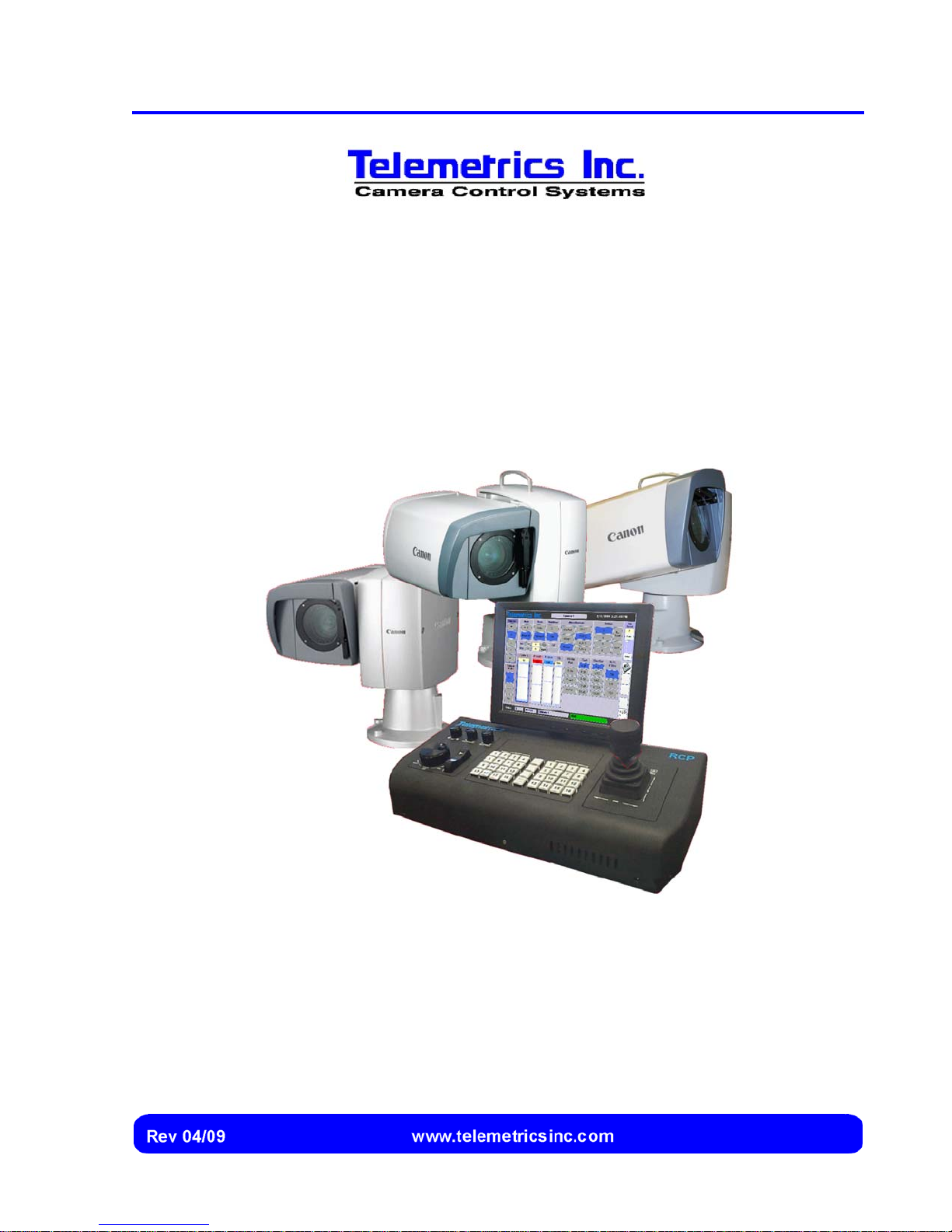
Canon BU 45 Camera
Control System
User’s Manual
Page 2

Revision History
Manual Software Version Firmware Version Description
April 2009 XXXX XXXX Initial issue.
Copyright
Copyright© 2009 Telemetrics Inc. All rights reserved. This material may not be
reproduced or copied, in whole or in part, without the written permission of
Telemetrics Inc.
Technical Support
Contact Telemetrics Inc. for technical support:
Telemetrics Inc.
6 Leighton Place
Mahwah, New Jersey, 07430
Phone: (201) 848-9818
Fax: (201) 848-9819.
Page 3

Preface
Text Conventions Used in this Manual
To convey information readily and consistently, certain text conventions are used
throughout this manual. These text conventions are as follows:
Text Convention Used for
Numbered Lists Numbered procedures that should be implemented in order
Bold Type Emphasis of any term or component that is being described:
during an operation:
1. Place the main power switch in the ON position.
2. Select a camera.
The Telemetrics RCP controls camera operations by
means of a joystick, knobs, pushbuttons, optional
rocker switch, and touch screen.
Italics Designating another section of this manual that should be
consulted, or designating the name of a screen:
The RCP Configuration screen is displayed. Refer to the
Installation and Setup section for additional information.
i
Page 4
Symbols
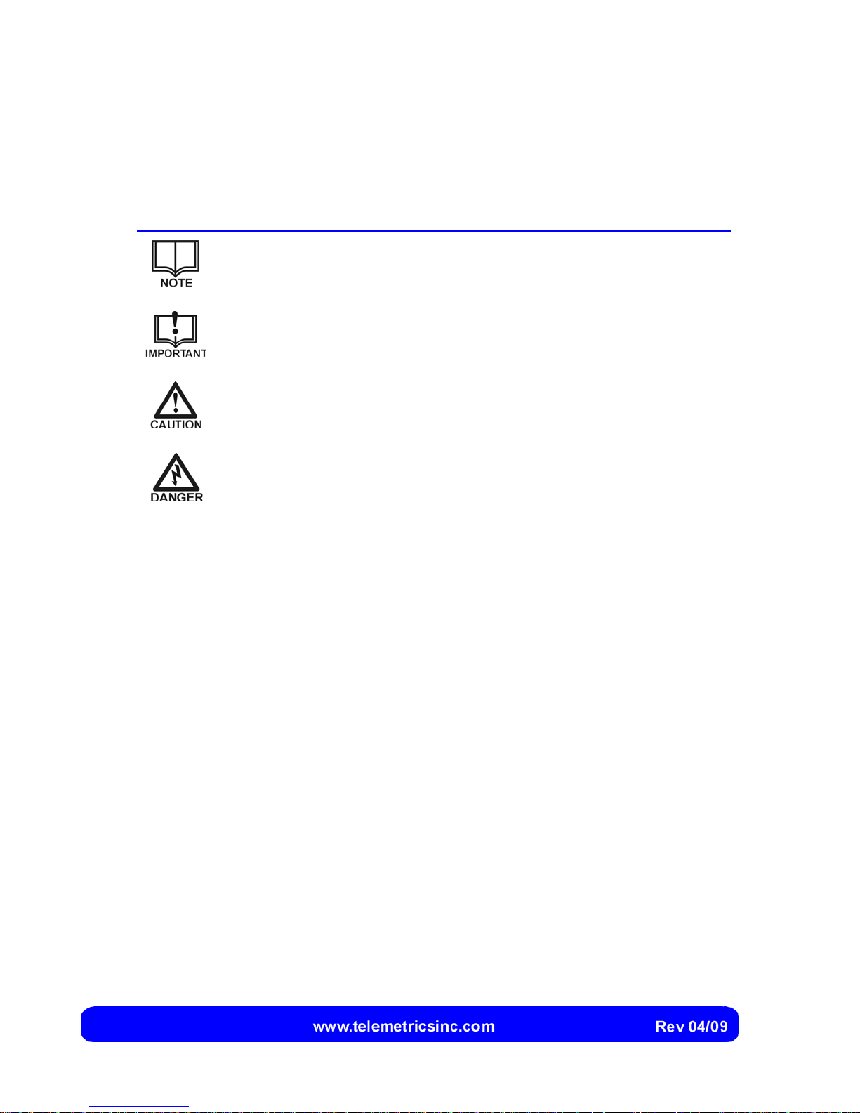
Certain symbols are used throughout this manual to provide a ready visual reference.
These symbols are as follows:
Symbol Used for
A note that provides background or incidental information
concerning the current topic or procedure.
A note that provides important information concerning
precautions that must be taken concerning the current topic or
procedure.
Indicates a possible hazardous situation which, if not avoided,
may result in personal injury and/or in damage to the system.
Indicates a possible hazardous situation which, if not avoided,
may result in personal injury due to electrical shock.
ii
Page 5

Table of Contents
PREFACE
Text Conventions Used in this Manual.......................................................i
Symbols..................................................................................................... ii
INTRODUCTION...............................................................................................................7
The Telemetrics Remote Control Panel (RCP)........................................................8
The Joystick...............................................................................................9
Knobs.........................................................................................................9
Pushbuttons...............................................................................................9
Software User Interface...........................................................................10
Highlighting of Buttons and Sliders..........................................................11
Backup Controls ......................................................................................12
Configuration Screens.............................................................................13
RCP Operating System and Software.....................................................13
RCP Mounting Configurations.................................................................13
RCP Connections to the Network............................................................14
Specifications.........................................................................................................14
Camera Control System Specifications...................................................14
Telemetric Remote Control Panel (RCP) Specifications .........................14
INSTALLATION AND SETUP........................................................................................15
Locating the Components ......................................................................................15
Locating the Remote Control Panel (RCP)..............................................15
Locating the Device Server DS-4 ............................................................16
Hubs or Switches.....................................................................................16
Installing the RCP...................................................................................................17
Preparing the RCP for Rack Mounting (Optional)....................................17
Securing the Touch Screen to the RCP...................................................18
Connecting the Touch Screen to the RCP...............................................19
Connecting an External Keyboard and/or Mouse....................................20
Connecting the RCP to the Power Source ..............................................21
Connecting the RCP(s) to the Camera(s) ..............................................................22
Connecting the RCP Directly to the DS-4 Device Server........................22
Connecting the RCP to a Hub or Switch..................................................23
iii
Page 6

Configuring the RCP(s).......................................................................................... 24
Displaying the RCP Configuration Screen...............................................24
Entering RCP Configuration Information..................................................26
Assigning Cameras to the RCP(s)......................................................................... 28
Adjusting the Touch Screen................................................................................... 31
Shutting Down and/or Re-Starting the RCP Computer.......................................... 32
Shutting Down the RCP Computer ..........................................................32
Shutting Down and Restarting the RCP Computer..................................32
Re-Calibrating the Touch Screen .......................................................................... 32
Updating Files on the Hard Drive........................................................................... 33
Copying Files to the C:/ Drive ..................................................................34
Disabling the Enhanced Write Filter.........................................................34
Re-Starting the Enhanced Write Filter .....................................................35
Reviewing Enhanced Write Filter Event Status........................................35
Installing Software Updates................................................................................... 36
OPERATION ...................................................................................................................37
Starting Up............................................................................................................. 37
Switching the Power On...........................................................................37
Selecting a Camera............................................................................................... 39
Controlling Pan, Tilt, Zoom, and Focus ................................................................. 40
Displaying Backup Controls and Digital Readings...................................40
Controlling Pan, Tilt, and Zoom Using the Joystick..................................41
Adjusting the Joystick Speed...................................................................41
Controlling Focus Using the Focus Wheel...............................................42
Controlling Pan, Tilt, Zoom, and Focus Using the Backup RCP Controls42
Capturing and Recalling Presets........................................................................... 43
Capturing a Preset...................................................................................43
Recalling a Preset Shot............................................................................44
Cutting vs. Fading to Preset Shots...........................................................44
Setting the Fade Time..............................................................................45
Specifying Camera Mode, Focus Mode, and Image Stabilizer.............................. 46
Camera Mode ..........................................................................................46
Focus Mode .............................................................................................47
Image Stabilizer .......................................................................................47
iv
Page 7

Switching Camera Power On or Off.......................................................................48
Using the Washer, Wiper, and Auxiliary Controls ..................................................49
Washer ....................................................................................................49
Wiper .......................................................................................................49
Auxiliary (AUX 1 to AUX 4)......................................................................49
Adjusting Iris and Master Black Settings................................................................50
Adjusting the Iris Setting..........................................................................50
Adjusting the Master Black Setting..........................................................50
Limiting Automatic Camera Mode to Automatic Exposure (Iris Control)..51
Adjusting Camera Settings.....................................................................................52
Displaying Camera Settings Instead of RCP Backup Controls................53
Adjusting the Red Gain Setting................................................................54
Adjusting the Blue Gain Setting...............................................................55
Adjusting the Genlock Setting..................................................................55
Specifying the White Balance Setting......................................................56
Generating Color Bars.............................................................................56
Changing the Gain Setting.......................................................................57
Changing the Shutter Setting...................................................................57
Specifying Use of a Neutral Density Filter...............................................57
Saving and Recalling Camera Settings (Scenes) ..................................................58
Capturing a Scene...................................................................................58
Recalling a Scene....................................................................................58
Re- Sending a Scene...............................................................................59
Shutdown ...............................................................................................................59
Switching the Power Off ..........................................................................59
TROUBLESHOOTING....................................................................................................61
Troubleshooting Chart............................................................................................61
Replacing the RCP Fuse........................................................................................63
INDEX .............................................................................................................................65
v
Page 8

This page intentionally left blank.
vi
Page 9
Introduction
The Canon BU 45 Camera Control System allows an operator to remotely control
multiple Canon BU 45 cameras (plus peripheral devices such as lights, audio mixers, or
recording devices) from one or more local or distant locations.
The system utilizes a Telemetrics Remote Control Panel (RCP) to control up to
sixteen cameras. The Telemetrics RCP allows the operator to select a camera station,
control the pan and tilt mechanism, switch camera power on or off, control camera lens
zoom and focus, control camera settings, and control lighting and other devices for the
camera station.
Many additional features, such as saving and recalling presets (for
reproducing a particular shot) and saving and recalling scenes (for
reproducing particular camera settings) are included. A listing of
specifications for the system is shown on page 14.
If needed, the system can include two or more Telemetrics RCPs. An
external video switcher can also be connected to provide a preview to the
operator, and controls for peripheral devices (such as an audio mixer or
lighting) can be obtained from Telemetrics.
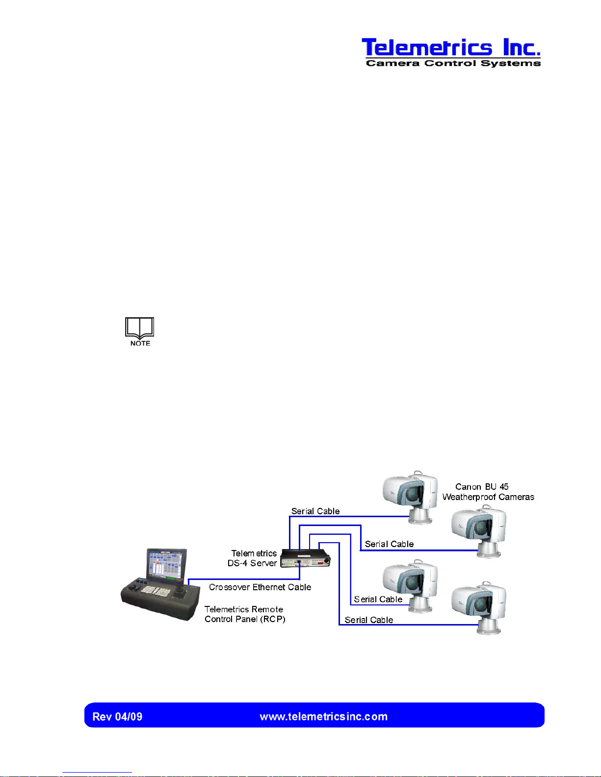
The cameras are linked to the Telemetrics RCP by means of the Telemetrics Device
Server DS-4 (Figure 1).
Figure 1 Canon BU 45 Camera Control System (Typical Example)
7
Page 10
Canon BU 45 Camera Control System User’s Manual
The Telemetrics Remote Control Panel (RCP)
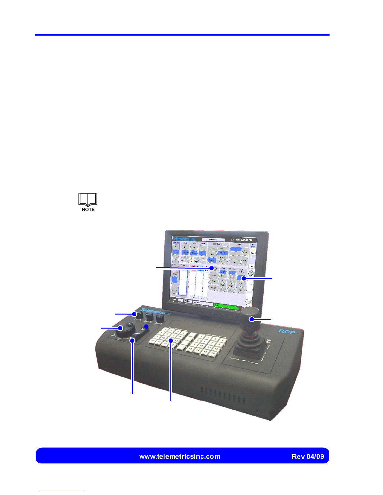
The Telemetrics RCP (Figure 2) controls camera operations by means of a joystick,
knobs, pushbuttons, optional rocker switch, and touch screen.
• The joystick is used to control camera pan and tilt and camera lens zoom.
• The knobs are used to control focus, iris, master black, and camera settings.
• The pushbuttons are used to select a camera and to save and recall preset shots.
• The optional rocker switch is used to elevate or lower the camera.
• The touch screen displays the connection status, information, and settings for the
currently selected camera, provides on-screen controls for switching camera
functions on or off and changing camera settings, and provides on-screen controls
that duplicate the functions of the joystick, rotary knobs, optional rocker switch, and
pushbuttons.
The speed at which pan, tilt, zoom, and focus settings are changed is
proportional to the deflection or rotation of the joystick (for pan, tilt and
zoom) or the rotation of the focus knob (for focus).
Rotary Knobs
Touch Screen
Knobs
Rocker Switch
(Optional)
On-Screen
Controls
Joystick
Pushbuttons
Figure 2 The Telemetrics Remote Control Panel (RCP)
8
Page 11

Introduction
The Joystick
The joystick allows the operator to control the position (pan and tilt) and zoom of the
camera with one hand. Moving the joystick in the forward and reverse directions
changes the tilt of the camera station, and moving the joystick in the left and right
directions changes the pan of the camera station.
Rotating the upper portion of the joystick causes the zoom to increase or decrease.
Rotating the joystick in the clockwise direction causes the zoom to increase, and rotating
the joystick in the counter-clockwise direction causes the zoom to decrease. The upper
portion of the joystick is spring-loaded, and releasing it causes the zoom setting to revert
to the nominal position.
Knobs
The knobs are used as described below:
Knob Description
Focus Wheel Changes the focus of the camera lens. Rotate the focus wheel
clockwise to focus on a more distant object, or rotate the focus
wheel counter-clockwise to focus on a nearer object..
Iris
Master Black Changes the camera master black setting, enabling the
User Selectable Change the setting for the slider that is currently selected on
Changes the camera lens aperture to compensate for lighting.
Rotate the knob clockwise to increase (open) the aperture (or
increase the intensity, or rotate the knob counter-clockwise to
decrease the aperture.
operator to set the black level for the darkest part of the
image. Rotate the knob clockwise to increase the black level,
or rotate the knob counter-clockwise to decrease the black
level.
the touch screen. Refer to the Operation section of this
manual for additional information.
Pushbuttons
Use of the pushbuttons is described on page 39 (for selecting a camera) and page 43
(for saving and recalling a preset shot).
9
Page 12
Canon BU 45 Camera Control System User’s Manual
r
r
Software User Interface
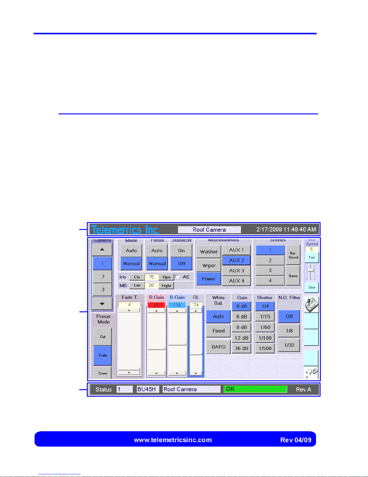
The RCP software user interface consists of a single Camera Control screen (Figure 3).
The Camera Control screen contains the information, controls, and indicators that are
used during routine operation:
Screen Section Description
Title Bar Contains the name of the camera that is selected and the current
date and time.
Camera Controls
Contains the controls (buttons, sliders, and a check box) that are
used for selecting and controlling a camera, a button for displaying
backup RCP controls, and buttons and sliders for configuring the
system.
Status Bar Contains the number, type, and name of the camera that is
selected, the status of the connection to that camera, and the
software version.
Title
Ba
Camera
Controls
Status
Ba
Figure 3 Camera Control Screen
10
Page 13
Introduction
Highlighting of Buttons and Sliders
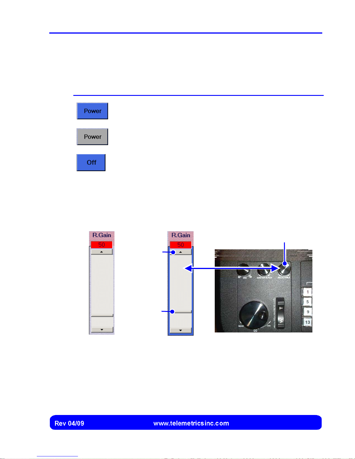
Buttons on the user interface are highlighted to designate the current selection or to
designate the activation status of a command:
Button Description
Power is switched on for the selected camera.
Power is switched off for the selected camera.
The function is switched off for the selected camera.
Whenever a slider is selected on the user interface, the slider is highlighted. The
corresponding setting can then be adjusted using either the slider button, the slider
arrows, or the User Selectable knob on the RCP:
Slider Not Selected: Slider Selected:
Slider
Arrow
Slider
Button
User Selectable Knob
11
Page 14
Canon BU 45 Camera Control System User’s Manual
Backup Controls
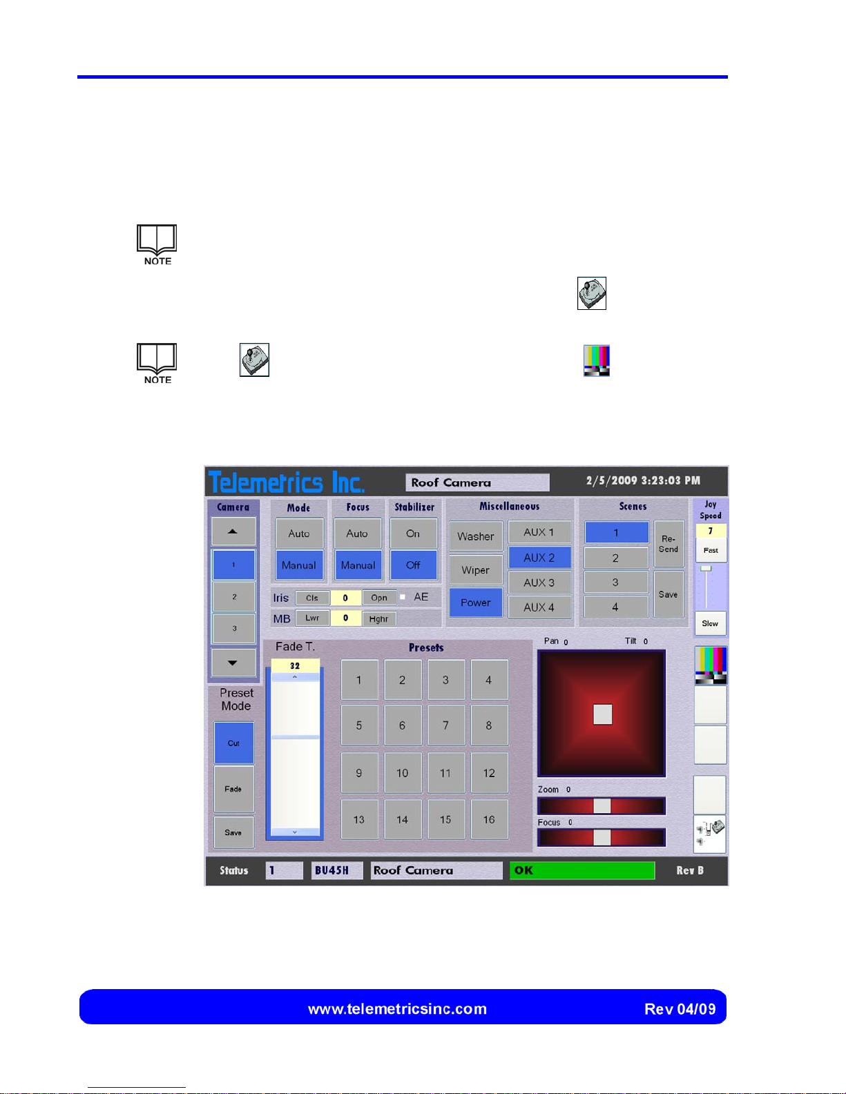
Backup controls for pan, tilt, zoom, focus, and the pushbuttons (plus camera elevation, if
the optional control is installed on the RCP) can be displayed instead of the camera
settings on the touch screen (Figure 4).
The backup controls show digital values for each of these controls so that
the settings can be recorded for future use.
The backup controls can be displayed at any time by selecting the
located at the right side the screen.
The button acts as a toggle and is replaced by the button (used to
display the camera settings again) whenever the backup controls are
selected.
button that is
Figure 4 Backup Controls
12
Page 15
Introduction
Configuration Screens
Two configuration screens (the RCP Configuration screen shown on page 25, and the
Camera Loading screen shown on page 28) allow the operator to specify IP address
information for the RCP, specify the length of inactivity time before the screen saver is
displayed, assign cameras to the RCP, and assign a name for each camera.
Refer to the Installation and Setup section of this manual for a detailed description of
each configuration screen and instructions for their use.
RCP Operating System and Software
The Telemetrics RCP utilizes an embedded Microsoft® Windows® XP operating system
to provide a familiar user interface for ease of integration and maintenance.
The RCP includes the Windows XP Enhanced Write Filter (EWF) to protect the
operating system and RCP software programs from write access, eliminating the threat
from viruses. The EWF can be turned off by the operator when necessary (such as when
updating a driver) and then turned back on.
The operating system and RCP software are installed on a removable compact flash
hard drive, allowing the operating system and RCP software to be readily replaced or
updated by simply replacing the compact flash hard drive.
RCP Mounting Configurations
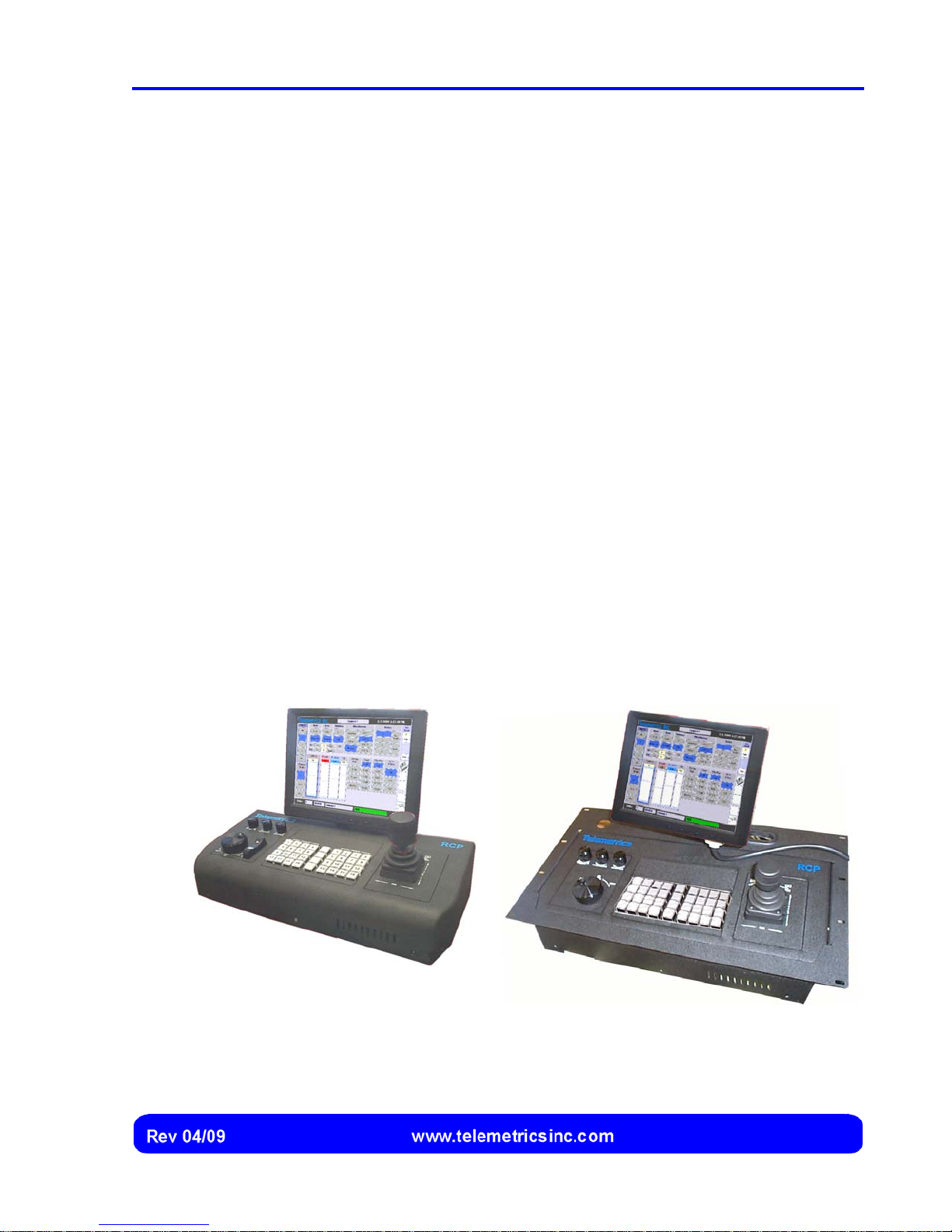
The Telemetrics RCP is provided in either a desktop or rack-mounted configuration
(Figure 5). Each configuration provides the same physical layout and identical controls
and touch screen.
Desktop Configuration
Figure 5 Telemetrics RCP Mounting Configurations
Rack-Mounted Configuration
13
Page 16

Canon BU 45 Camera Control System User’s Manual
RCP Connections to the Network
Duplicate Ethernet connections on the Telemetrics RCP allow redundant network
connections can be made to each camera if needed. Status of the network connection(s)
to the selected camera is included on the RCP user interface.
Details concerning the network connections, including the additional hardware devices
that are required, are provided in the Installation and Setup section of this manual.
Specifications
Specifications for the Telemetrics Canon BU 45 Camera Control System are
summarized below:
Camera Control System Specifications
Cameras Up to 16 Canon BU 45 cameras can be controlled by the
system
Telemetric Remote Control Panel (RCP) Specifications
Display 10.4 inch VGA touch screen
1024 x 768 maximum resolution
Brightness: 350 cd/m2
Contrast: 250:1
Joystick Three-axis with proportional control for pan and tilt
Tactile control· Spring-loaded knob on top for zoom, which
returns to the center upon release
Via Eden Mini ITX
Motherboard
Ethernet Ports Dual 10/100 MBS
1 GHz CPU
512 MB RAM
4 GB CP FLASH
14
Page 17
Installation and Setup
Locating the Components
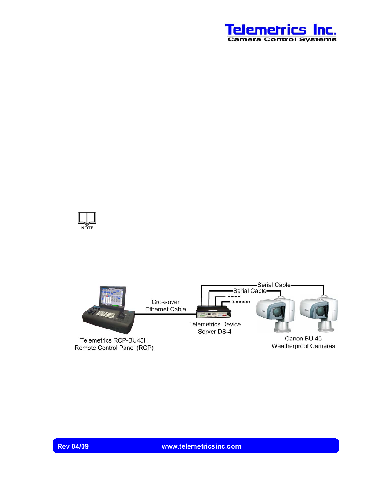
The cameras are connected to the Telemetrics Device Server DS-4 by means of serial
cables, and the Device Server is connected to the Remote Control Panel (RCP) by an
Ethernet connection (see Figure 6 and Figure 7 for examples).
Locating the Remote Control Panel (RCP)
The Telemetrics Remote Control Panel (RCP) is linked to the cameras by means of an
Ethernet connection. The RCP can be located anywhere.
A Telemetrics Device Server DS-4 is used for connecting the cameras to
the Ethernet. Up to four cameras can be connected to one Device Server
DS-4 (Figure 6).
Consult the documentation that accompanies the Telemetrics Device Server
DS-4 and the Canon BU 45 Weatherproof Camera for additional information
concerning locating and connecting these products.
Figure 6 Example of an Installation Using a Single Device Server DS-4
15
Page 18
Canon BU 45 Camera Control System User’s Manual
Locating the Device Server DS-4
The Device Server DS-4 must be located so that it can be reached by the serial cables
(with a maximum length of approximately 50 feet) that are used to connect the cameras
to the DS-4.
Consult the documentation that accompanies the Telemetrics Device Server
DS-4 and the Canon BU 45 Weatherproof Camera for additional information
concerning locating and connecting these products.
Hubs or Switches
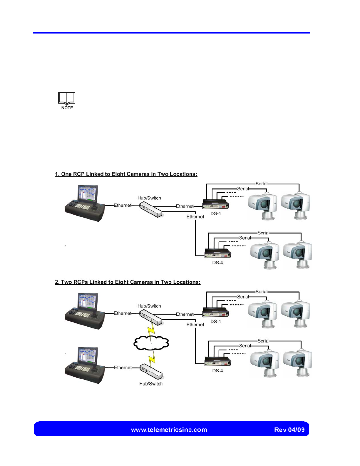
If more than one DS-4 Device Server is used, if more than one RCP is used, or if the
cameras are installed at different locations, the RCP is linked to Device Server DS-4
units by means of a hub or switch (Figure 7).
Figure 7 Example of Installations Using More Than One Device Server DS-4
16
Page 19
Installing the RCP
The RCP can be installed as either a desktop or rack-mounted configuration. In either
case, the touch screen must be secured to the RCP and connected before the RCP can
be configured and used.
Preparing the RCP for Rack Mounting (Optional)
For a rack-mounted installation, use the RCP Rack Mount Kit (Telemetrics Part No.
XXXX).
Contact your Telemetrics representative for information on obtaining an
RCP Rack Mount Kit.
1. Obtain the RCP Rackmount kit.
2. If the RCP is currently being used in the desktop configuration, disconnect
the RCP power cable. Then disconnect the power, VGA, and USB leads at
the end of the touch screen interface cables from their respective connectors
on the touch screen and the RCP.
Installation and Setup
3. Secure the RCP Rack Adaptor to the sides of the RCP using the six flat head
cap screws, ensuring that the top surface of the RCP is flush and parallel with
the top surface of the RCP Rack Adaptor.
4. Obtain the appropriate screen interface cable and connect the power, VGA,
and USB leads to their connectors on the RCP (refer to page 20 for details).
If the touch screen will be mounted on the RCP Rack Adapter,
use the 2-foot screen interface cable. If the touch screen will be
flush-mounted on the RCP Rack Mount, use the 7-foot screen
interface cable.
5. Route the screen interface cable through the panel grommet.
6. Connect the power and VGA leads to their connectors on the touch screen
(refer to page 19 for details).
7. Mount the RCP Rack Adaptor and the Rack Mount (if used).
17
Page 20
Canon BU 45 Camera Control System User’s Manual
Securing the Touch Screen to the RCP
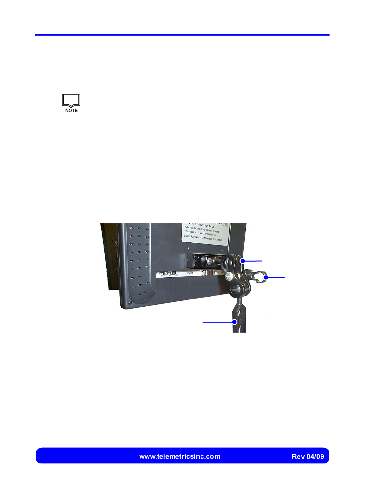
The touch screen is attached to the rear of the RCP by means of the ball-and-socket
arm and clamps that are provided.
If the RCP is rack-mounted, the ball-and-socket arm is attached to the top of
the RCP instead of the rear.
1. Loosely secure one end of the ball-and-socket arm to the rear of the touch
screen, using one of the clamps provided (Figure 9).
2. Loosely secure the other end of the arm to the RCP, using the remaining
clamp.
3. Adjust the height and position of the touch screen so that it can be
comfortably used, then tighten the upper and lower keys until the touch
screen remains in position when supported by the RCP.
Clamp
Key
Ball-and-Socket Arm
Figure 8 Securing the Touch Screen to the Ball-and-Socket Arm
18
Page 21

Installation and Setup
Connecting the Touch Screen to the RCP
After the touch screen is attached, it should be connected to the RCP using the touch
screen power and communication cables that are provided.
1. Connect the end of the touch screen power cable with the smaller connector
to the power terminal on the touch screen (Figure 9).
2. Connect the end of the touch screen communication cable with the single
connector to the VGA terminal on the touch screen (Figure 9).
The end of the communication cable with the single VGA
connector must be connected to the touch screen. The two
connectors at the other end must be connected to the RCP.
Connect to RCP Connect to Touch Screen
Power Cable
Communication Cable
Figure 9 Connections at the Touch Screen
19
Page 22
Canon BU 45 Camera Control System User’s Manual
A
3. Connect the other end of the touch screen power cable to the screen power
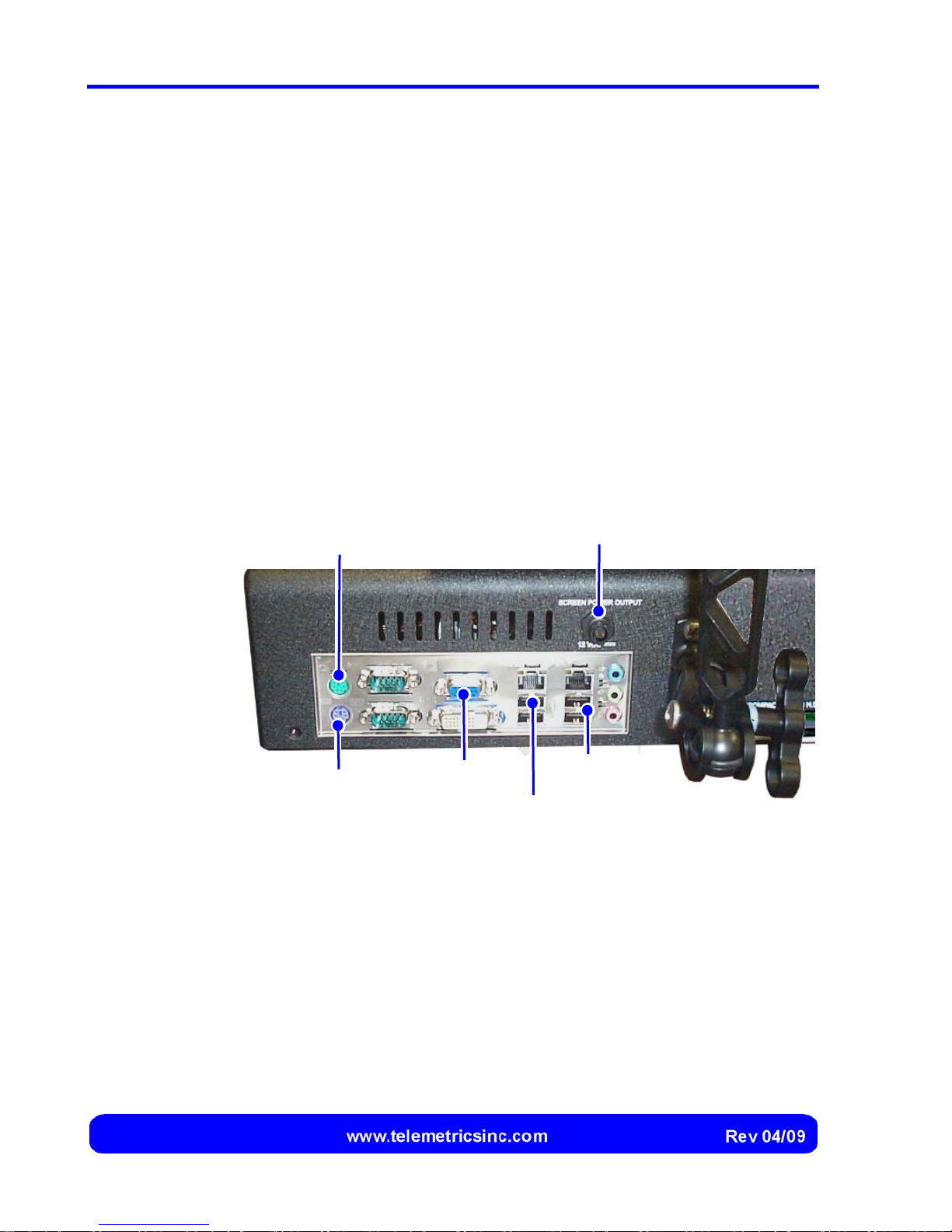
outlet connector at the rear of the RCP (Figure 10).
4. Connect the VGA and USB connectors at the other end of the touch screen
communication cable to the VGA and USB connectors at the rear of the RCP
(Figure 10).
Connecting an External Keyboard and/or Mouse
If desired, an external PS/2 or USB keyboard and/or a PS/2 or USB mouse can be used.
1. If a PS/2 keyboard and/or mouse are used, connect either or both using the
PS/2 connectors at the rear of the RCP (Figure 10).
2. If a USB keyboard and/or mouse are used, connect either or both using the
additional USB connectors at the rear of the RCP (Figure 10).
PS/2 Mouse
(Optional)
PS/2 Keyboard
(Optional)
Touch Screen
VGA
Touch Screen
Touch Screen
Power Outlet
dditional USB
Ports
USB Port
Figure 10 Touch Screen and Optional Mouse and/or Keyboard
Connections
20
Page 23
Installation and Setup
Connecting the RCP to the Power Source
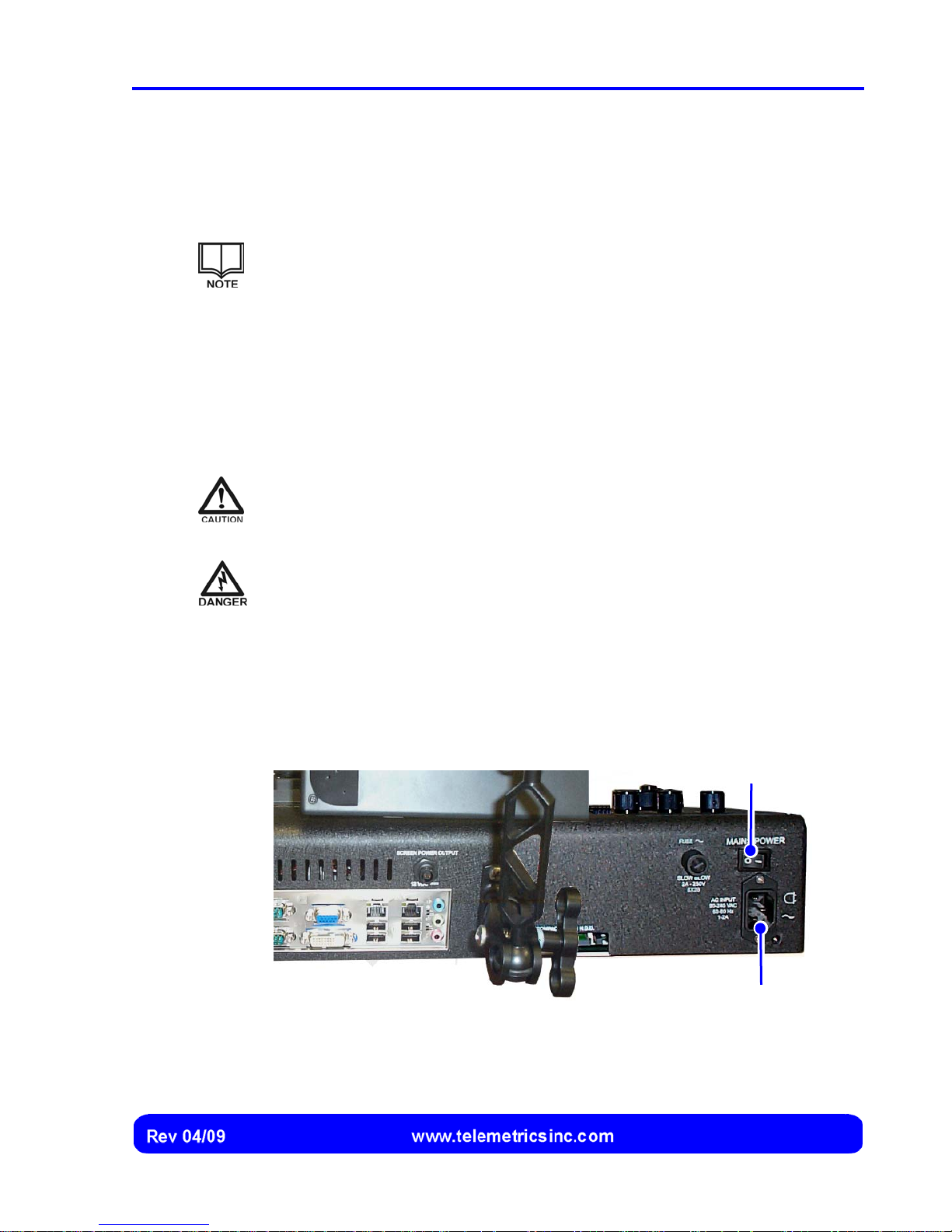
An AC power cord is provided for use with the three-prong AC input connector on the
RCP (Figure 11).
Grounding of the RCP and those surfaces the user can come into contact
with is provided by grounded cables in accordance with Protection Class I
(IEC).
For protection against electrical shock hazards, each RCP must be directly
connected to an approved power source such as a 3-wire grounded
receptacle. Where an ungrounded receptacle is encountered, a qualified
electrician must replace it with a properly grounded receptacle in
accordance with the facility electrical code.
An extension cord must not be used.
If the power cable becomes cracked, frayed, broken, or otherwise damaged,
it must be replaced immediately with the equivalent part from Telemetrics.
Any break in the electrical ground path, whether inside or outside the RCP,
may create a hazardous condition. Under no circumstances should the user
attempt to modify or deliberately defeat the safety features of the RCP.
1. Using the power cable provided, connect the AC Power Input to an approved
power source.
Power Switch
AC Power Input
Connection
Figure 11 RCP Power Input and Power Switch
21
Page 24
Canon BU 45 Camera Control System User’s Manual
Connecting the RCP(s) to the Camera(s)
Typical installations are summarized in Figure 6 and Figure 7.
Connecting the RCP Directly to the DS-4 Device Server
The RCP can be connected directly to the DS-4 Device Server if no more than four
cameras are installed within approximately 300 feet of the RCP and they are all
connected to the same DS-4.
In this case, an Ethernet crossover cable is used to connect the RCP to the DS-4.
If you have questions concerning the components that are required for a
particular installation, contact your Telemetrics representative.
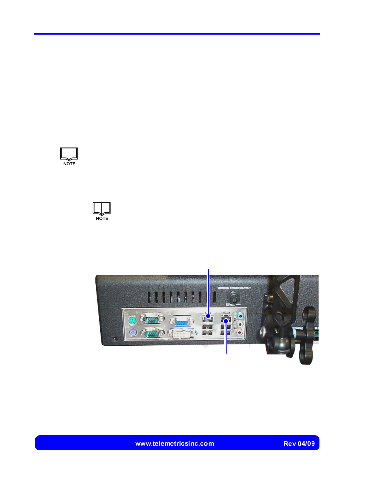
1. Connect one end of the Ethernet crossover cable to the main Ethernet
connection on the RCP (Figure 12).
The backup Ethernet connection is not used when a single DS-4
is connected to the RCP.
2. Connect the other end of the Ethernet crossover cable to the DS-4 Device
Server.
Main Ethernet Connection
(Connect Ethernet Crossover Cable Here)
Backup Ethernet Connection
(Do Not Use)
Figure 12 Connecting an RCP Directly to a Single DS-4 Device Server
22
Page 25
Installation and Setup
Connecting the RCP to a Hub or Switch
The RCP is connected to a hub or switch if more than one DS-4 Device Server is used, if
more than one RCP is used, or if the cameras are installed further than approximately
300 feet from the RCP.
A standard Ethernet cable is used to connect the RCP to the hub or switch.
Refer to the documentation for the hub or switch for information concerning
the type of cable and connections that are followed when connecting the
RCP to the hub or switch.
If you have questions concerning the components that are required for a
particular installation, contact your Telemetrics representative.
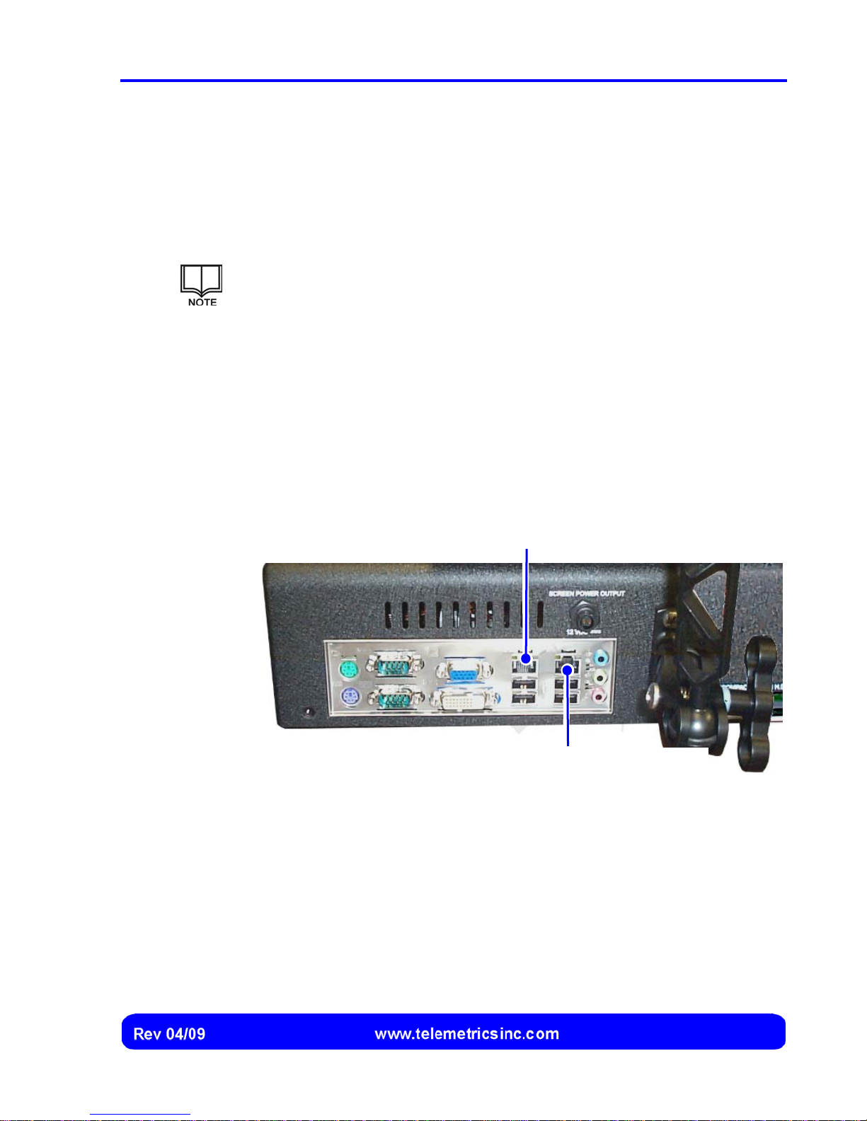
1. Connect one end of one Ethernet cable to the main Ethernet connection on
the RCP (Figure 13), and connect the other end of the cable to the input port
of the hub or switch.
2. Connect the other end of the Ethernet cable to the input port of the hub or
switch.
Main Ethernet Connection
(Connect Ethernet Crossover Cable Here)
Backup Ethernet Connection
(Do Not Use)
Figure 13 Connecting an RCP to a Hub or Switch
23
Page 26
Canon BU 45 Camera Control System User’s Manual
Configuring the RCP(s)
After installing and connecting the RCP(s) and camera(s), (see pages 15 through 23 for
details), each RCP must be configured using the RCP Configuration screen.
Displaying the RCP Configuration Screen
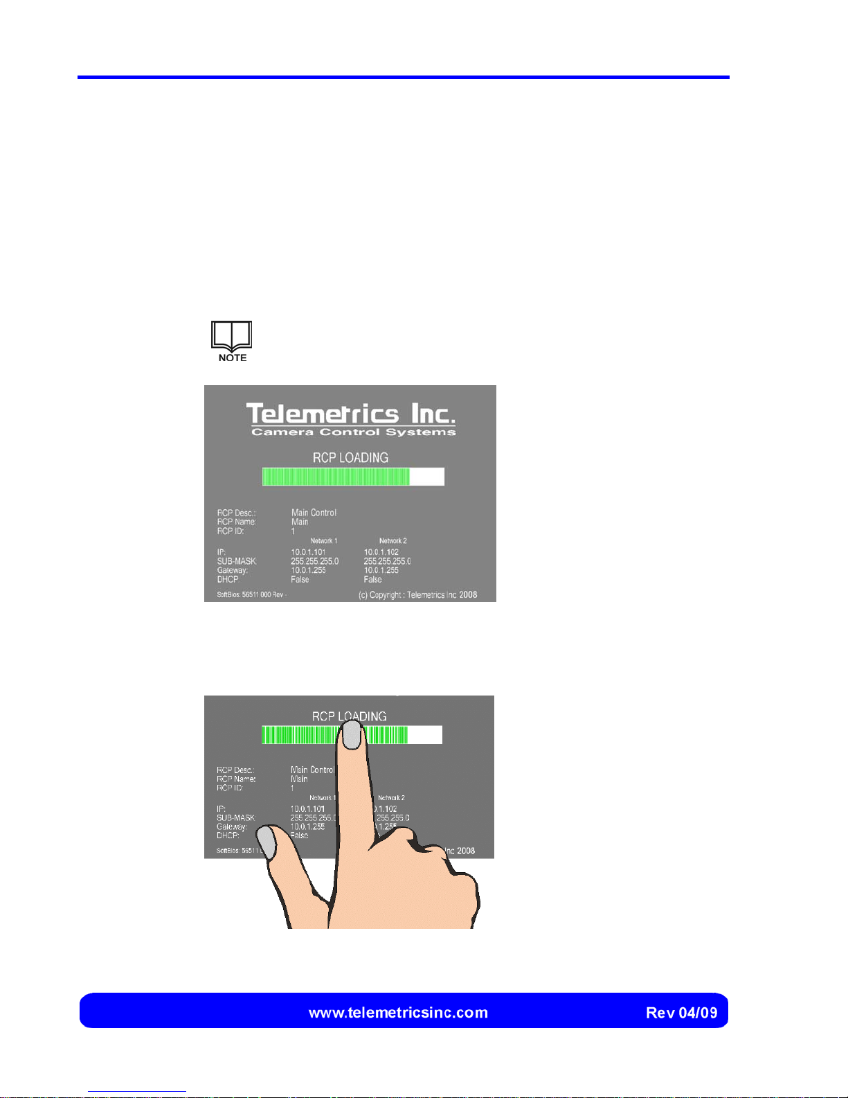
1. Place the RCP main power switch in the ON position, then press the power
button at the bottom of the touch screen. The system initializes, and the RCP
Loading screen is momentarily displayed on the touch screen (Figure 14).
The main power switch is located at the rear of the RCP (see
Figure 11 on page 21).
Figure 14
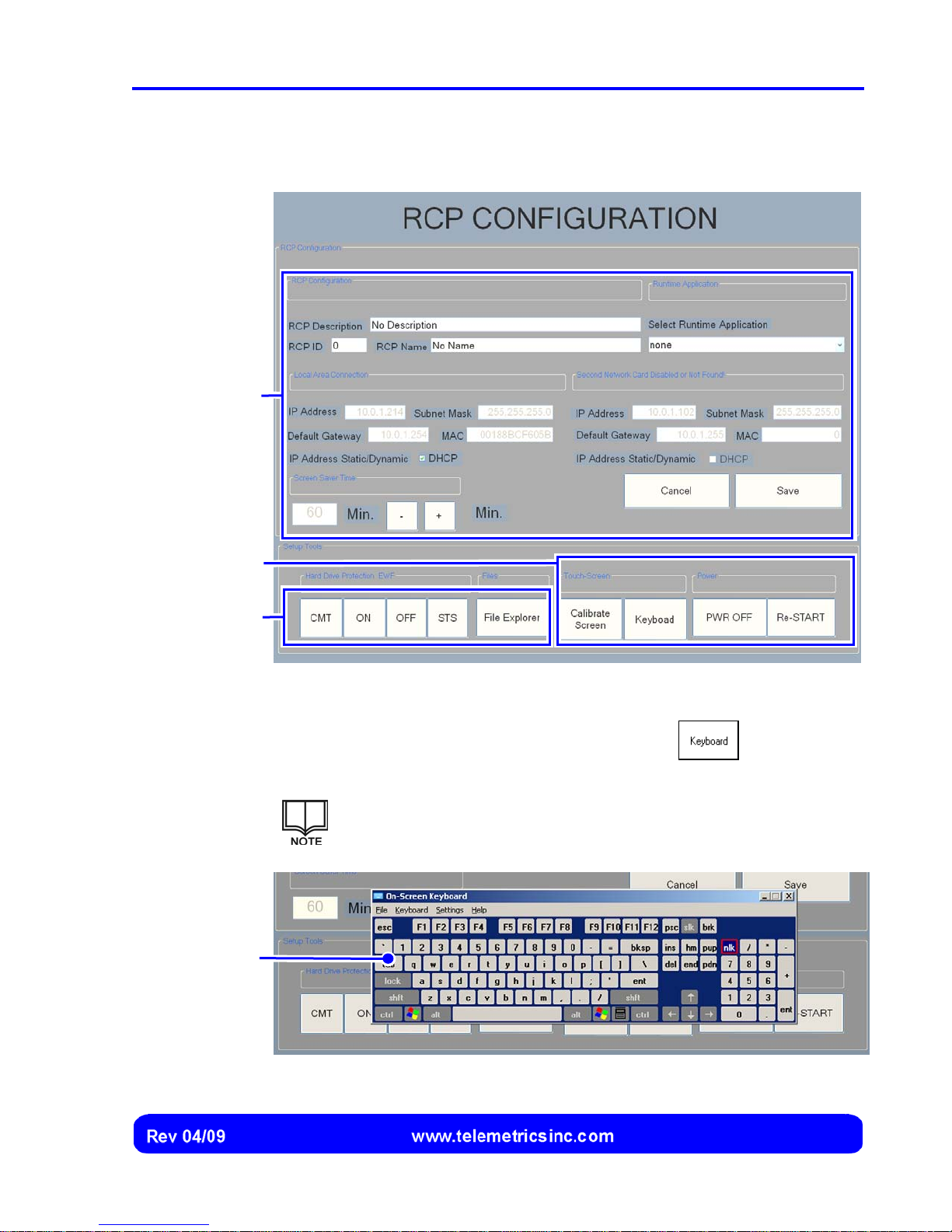
2. Select the progress bar on the RCP Loading screen (Figure 15).
Figure 15 Selecting the Progress Bar on the
RCP Loading
Screen
RCP Loading
Screen
24
Page 27
RCP Setup
Information
Installation and Setup
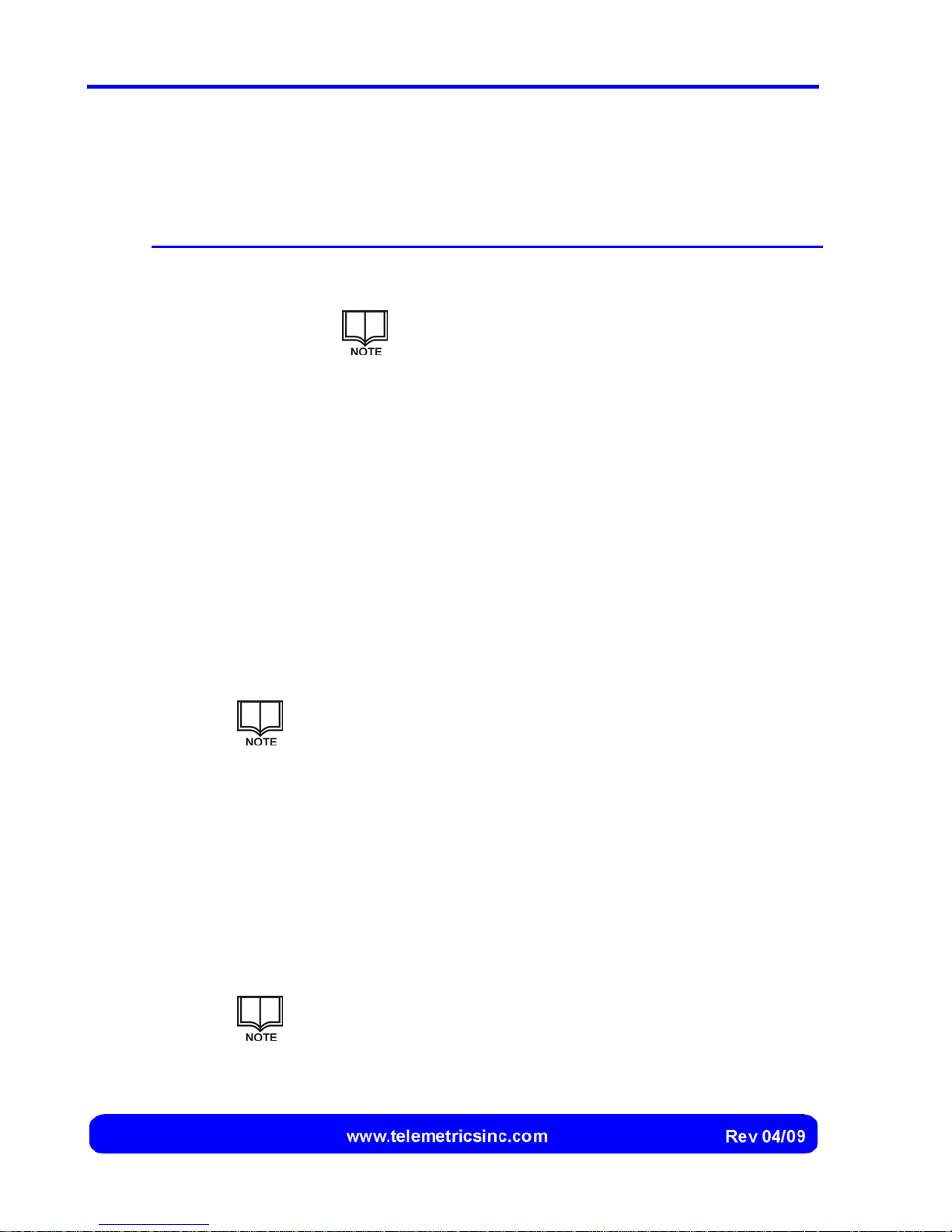
3. After the system has initialized and the software has loaded, the RCP
Configuration screen is displayed (Figure 16).
General
Tools
Hard Drive
Tools
Keyboard
Figure 16
RCP Configuration
Screen
4. If a keyboard is not connected to the RCP, select the
a keyboard over the RCP Configuration screen (Figure 19):
If needed, select the title bar on the keyboard and drag the
keyboard to a different location on the touch screen.
button to place
Figure 17 Keyboard
25
Page 28
Canon BU 45 Camera Control System User’s Manual
Entering RCP Configuration Information
The following information must be entered for each RCP:
Information Description
RCP Configuration A short free-text description of the RCP, a number to identify
the RCP, and a short name for the RCP.
This information is not required if only one RCP is
installed.
Runtime Application The resident software application used for operating the RCP.
Local Area
Connection
Address of the main network card connection on the RCP,
plus a designation of whether the dynamic host configuration
protocol (DHCP) is to be used for that connection.
Second Network
Card Connection
Address of the backup network card connection on the RCP,
plus a designation of whether the dynamic host configuration
protocol (DHCP) is to be used for that connection.
Screen Saver Time Length of inactivity time before displaying the screen saver.
1. RCP Configuration: If more than one RCP is installed, enter configuration
information for the RCP:
If only one RCP is installed, this step can be ignored.
a. Select the RCP Description box, then type a short free-text description of
the RCP.
b. Select the RCP ID box, then type a one- or two-digit number to identify
the RCP.
c. Select the RCP Name box, then type a short (up to eight characters)
name for the RCP.
2. Runtime Application: Select the runtime application that will be used for the
RCP:
The runtime application will be specified by Telemetrics
representatives during installation. .
26
Page 29
Installation and Setup
3. Local Area Connection: Enter information about the main network card on
the RCP:
a. Select the IP Address box, then type the IP address of the main network
card.
b. Select the Subnet Mask box, then type the subnet mask address of the
main network card.
c. Select the Default Gateway box, then type the default gateway address of
the main network card.
d. If the MAC box is not automatically populated, select the MAC box, then
type the media access control address for the main network card.
e. If the dynamic host configuration protocol (DHCP) is to be used for the
main Ethernet connection to the RCP, select the DHCP check box to
place a check mark in it. Otherwise, leave the check box blank.
4. Backup Local Area Connection: Enter information about the backup
network card on the RCP:
a. Select the IP Address box, then type the IP address of the backup
network card.
b. Select the Subnet Mask box, then type the subnet mask address of the
network card.
c. Select the Default Gateway box, then type the default gateway address of
the backup network card.
d. If the MAC box is not automatically populated, select the MAC box, then
type the media access control address for the backup network card.
e. If the dynamic host configuration protocol (DHCP) is to be used for the
backup Ethernet connection to the RCP, select the DHCP check box to
place a check mark in it. Otherwise, leave the check box blank.
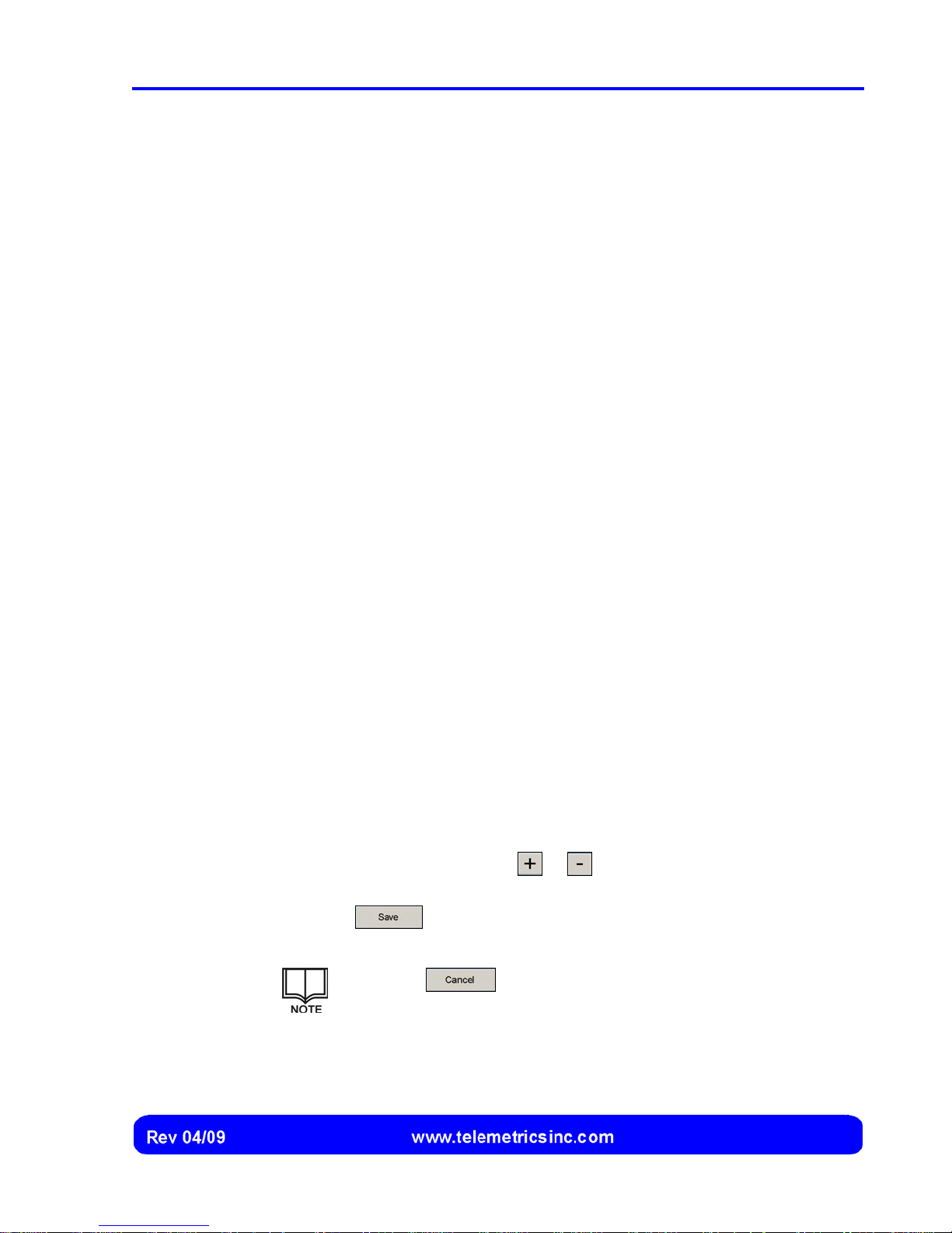
5. Screen Saver Time: Select the
or button to increase or decrease the
length of inactivity time (in minutes) before the screen saver is displayed.
6. Select the
button to save the configuration information. The RCP
must be shut down and restarted to complete the configuration process.
Select the button to cancel display of the RCP
Configuration screen without saving the information.
27
Page 30
Canon BU 45 Camera Control System User’s Manual
Assigning Cameras to the RCP(s)
Up to sixteen cameras can be included in the camera control network. After the cameras
have been installed and connected to one or more RCPs (see pages 15 through 23), the
cameras must be assigned to each RCP so they can be recognized.
Before cameras can be assigned to the RCPs, setup information must be
entered for each RCP as described on page 24.
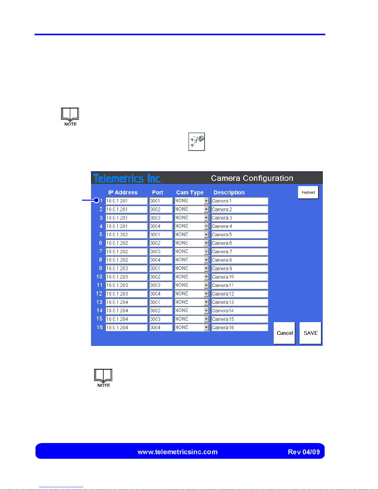
1. Select the camera configuration
Camera Configuration screen is displayed (Figure 18).
Line 1
button on the RCP touch screen. The
Figure 18 Camera Configuration Screen
Start at line 1 (Figure 18) when configuring the first camera.
Configure each additional camera using the next available line.
The configuration line number, camera type, and camera
description are displayed in the status bar of the RCP touch screen
whenever that camera is selected (page 10).
28
Page 31
Keyboard
Installation and Setup
2. If a keyboard is not connected to the RCP, select the button to
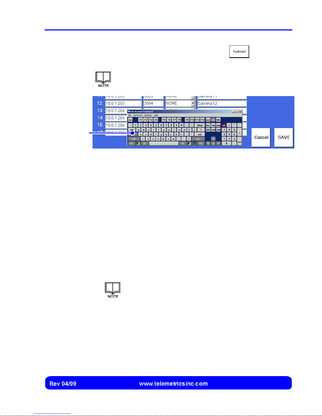
superimpose a keyboard over the Camera Configuration screen (Figure 19):
If needed, select the title bar on the keyboard and drag the
keyboard to a different location on the touch screen.
Figure 19 Keyboard
3. Configure each camera that is connected to the RCP, entering (using the
keyboard) or selecting (using the drop-down arrows) the information for each
camera on the first available line of the Camera Configuration screen.
a. Select the IP Address box, then type the IP address (e.g., 10.0.1.211) of
the device server to which the camera is connected.
b. Select the Port box, then type the number (e.g., 3001) of the serial port on
the device server to which the camera is connected.
c. Select the drop-down arrow of the Cam Type box, then select the type of
camera (e.g., BU45H) that is connected.
d. If desired, select the Description box, then type a short name (up to 18
characters or spaces) or description (e.g., Roof Camera) for the camera
to replace the default description (e.g., Camera 1).
The short name or description for the camera is displayed at
the top and bottom of the RCP touch screen whenever that
camera is selected (page 10).
29
Page 32
Canon BU 45 Camera Control System User’s Manual
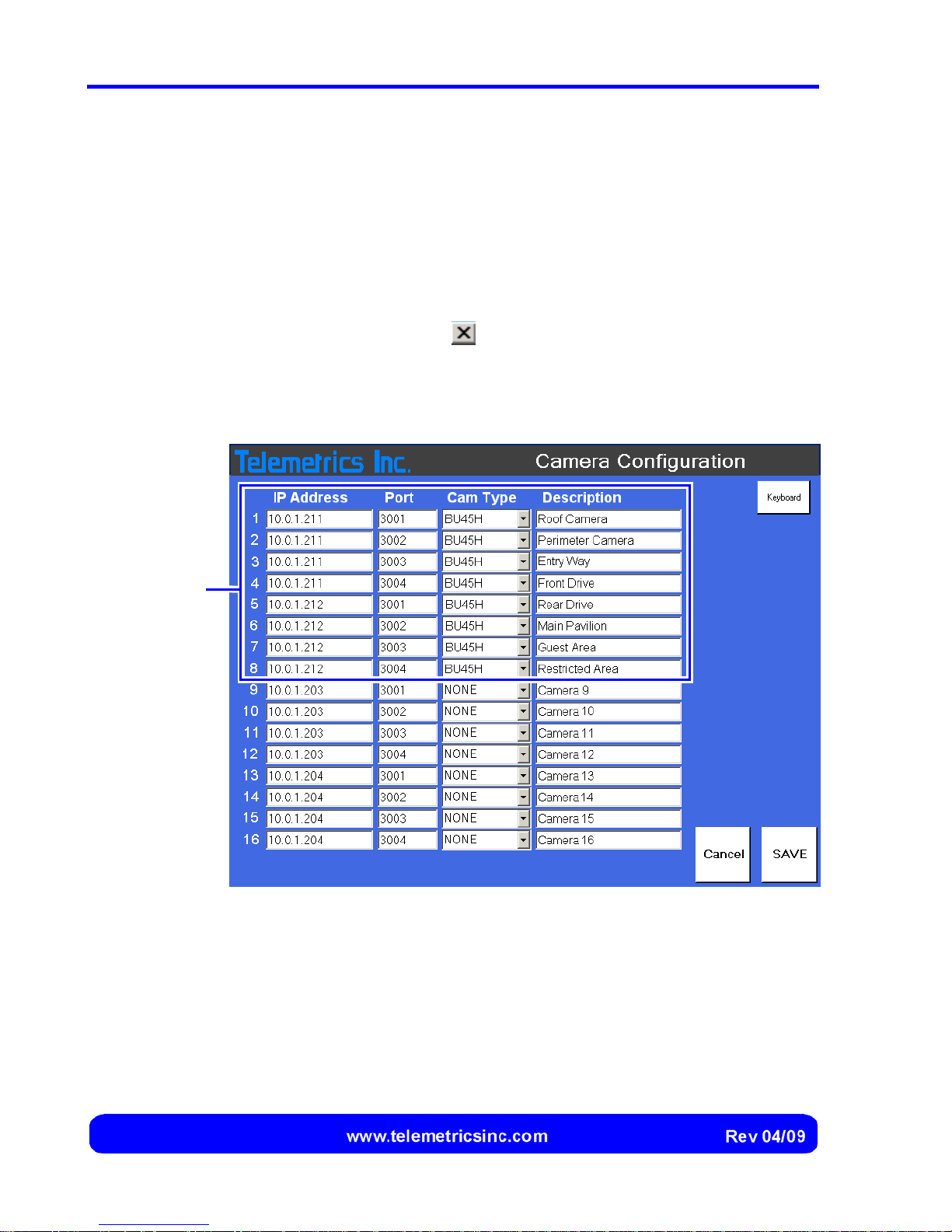
4. After information for each connected camera has been entered or selected
(see Figure 20 for an example), check the entries to verify the following:
• Correct IP addresses and ports are entered for each installed camera
• BU45H is selected for each installed camera
• NONE is displayed in the Cam Type field in all unused lines
5. Select the Save button to save the information.
Configured
Cameras
6. (If needed) Select the cancel
button to cancel display of the keyboard.
7. Repeat Steps 1 through 6 for any remaining RCPs, ensuring that identical
line numbers are used and identical information is entered for each camera.
Figure 20 Example of Completed Camera Configuration
30
Page 33
Adjusting the Touch Screen
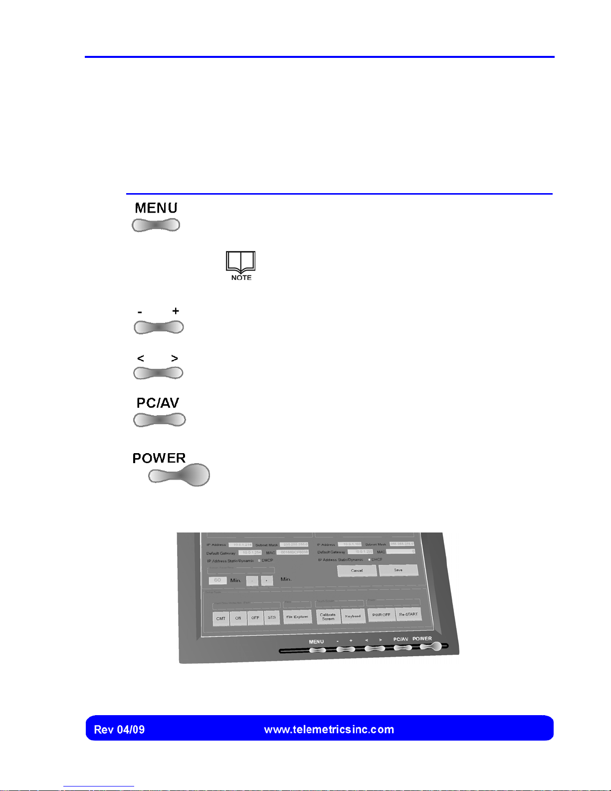
Controls on the touch screen (Figure 21) allow the operator to switch the touch screen
power on of off, adjust the display brightness and position, and display a menu that
contains additional commands:
Control Description
Display an on-screen menu that includes commands for changing
the brightness, contrast, size, shape, and position of the image on
the screen.
Installation and Setup
Decrease (-) or increase (+) the current setting.
Display the previous (<) or next (>) setting.
Toggles the operating mode between PC (personal computer)
and
AV (audio visual). The PC operating mode should be used.
Switch the touch screen power on or off.
Consult the documentation that accompanies the touch
screen for detailed instructions concerning the touch
screen adjustments.
Figure 21 Touch Screen Controls
31
Page 34
Canon BU 45 Camera Control System User’s Manual
Shutting Down and/or Re-Starting the RCP Computer
The RCP computer must be shut down and re-started after certain operations (such as
disabling or restarting the Enhance Write Filter) are performed.
The RCP computer is shut down whenever the RCP power switch is turned off.
However, this also shuts down the touch screen, which must then be re-started
(by pressing the touch screen power button) when the RCP is re-started.
Shutting Down the RCP Computer
1. Display the RCP Configuration screen (page 24), then select the
button. The RCP computer is shut down, but the touch screen remains on.
Shutting Down and Restarting the RCP Computer
1. Display the RCP Configuration screen (see page 24 for instructions).
2. Select the
touch screen on.
button to shut down and restart the CPU while leaving the
Re-Calibrating the Touch Screen
The touch screen should be re-calibrated if the touch points on the screen do not
coincide with the elements of the user interface.
The touch screen is calibrated at the factory. Re-calibration is not necessary
unless a button or other element does not respond when it is touched.
1. Display the RCP Configuration screen (see page 24 for instructions).
2. Select the
3. Follow the instructions that are displayed on the screen. The RCP computer
is automatically shut down and restarted when the re-calibration is
completed.
button.
32
Page 35
Updating Files on the Hard Drive
It may be necessary to occasionally update a driver or replace a file on the compact
flash card (the RCP “hard drive”), which contains the operating system and software
programs for the RCP.
To protect the system, the compact flash card is partitioned into C:/ and D:/ drives:
• The C:/ Drive contains the operating system and software programs for the RCP.
The C:/ drive is protected by the Enhanced Write Filter (EWF) and cannot be
overwritten unless the new files are committed by the operator (see below) or the
EWF is disabled (page 34).
• The D:/ Drive contains camera information and settings that are updated during
operation. The D:/ drive is not protected.
The “hard drive” tools on the RCP Configuration screen (Figure 16) allow the user to
view and manage the files contained on the compact flash card:
Tool Description
Installation and Setup
Commits pasting of new or updated files to the protected partition on
the flash card, allowing them to be written to the C:/ drive.
Enables Enhanced Write Filter protection on the C:/ drive, preventing
files from being written to that drive.
Disables Enhanced Write Filter protection on the C:/ drive, allowing
files to be written to that drive.
Displays a dialog box with Enhanced Write Filter status messages.
Displays the contents of the flash card in the Explorer view.
33
Page 36
Canon BU 45 Camera Control System User’s Manual
Copying Files to the C:/ Drive
1. Display the RCP Configuration screen (see page 24).
2. Select the
button to display the contents of the flash card in the
Explorer view.
3. Copy and paste the file(s) to the C:/drive.
4. Select the
button to commit writing of the files to the C:/ drive. A
message box is displayed, prompting confirmation.
5. Acknowledge the confirmation.
6. Select the
button to shut down and restart the RCP computer.
Disabling the Enhanced Write Filter
The Enhanced Write Filter can be disabled if a large number of files are to be copied to
the C:/ drive.
The Enhanced Write Filter prevents the RCP operating system software and
camera control software from being corrupted. Do not disable the EWF
unless you are certain of the outcome.
Never remove the flash card while the Enhanced Write Filter is disabled
unless the RCP is shut down.
34
1. Display the RCP Configuration screen (see page 24).
2. Select the
button to disable Enhanced Write Filter protection on the C:/
drive. A message box is displayed, prompting confirmation.
3. Acknowledge the confirmation.
4. Select the
button to shut down and restart the RCP computer with
the Enhanced Write Filter protection on the C:/ drive disabled.
Page 37
Re-Starting the Enhanced Write Filter
1. Display the RCP Configuration screen (see page 24).
Installation and Setup
2. Select the
drive. A message box is displayed, prompting confirmation.
3. Acknowledge the confirmation.
4. Select the
the Enhanced Write Filter protection on the C:/ drive enabled.
button to ensable Enhanced Write Filter protection on the C:/
button to shut down and restart the RCP computer with
Reviewing Enhanced Write Filter Event Status
A listing of Enhanced Write Filter events and their status can be displayed by the
operator at any time.
1. Display the RCP Configuration screen (see page 24).
2. Select the
Enhanced Write Filter events and their status.
3. After reviewing the Enhanced Write Filter events and their status, select the
OK button to cancel display of the dialog box.
button. A dialog box is displayed, containing a listing of
35
Page 38
Canon BU 45 Camera Control System User’s Manual
Installing Software Updates
The RCP operating system and software are installed on a removable compact flash
hard drive. The operating system and software can be replaced or updated by replacing
the compact flash hard drive with a new one containing the new software already
installed.
To prevent corruption of the C:/: drive, always shut down the RCP before
removing the flash card.
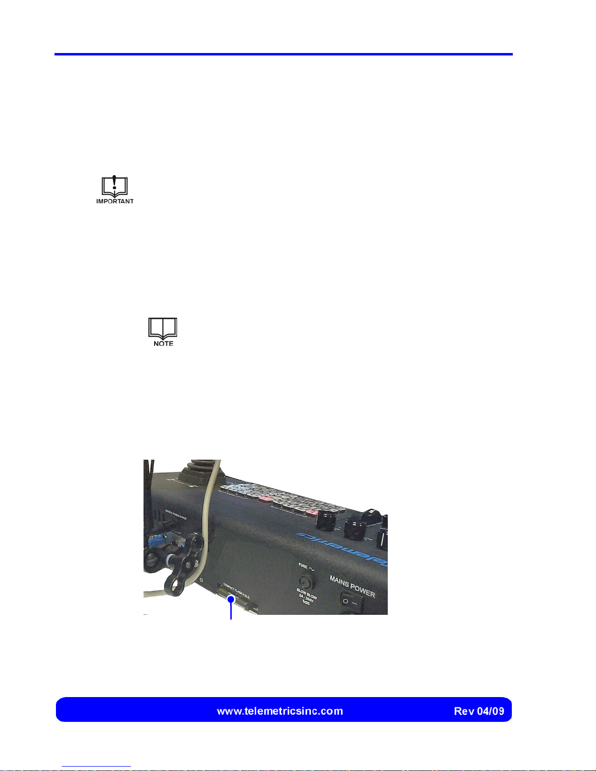
1. After shutting down the RCP, access the rear panel of the RCP (Figure 22).
2. Push the retainer button (located just to the left of the compact flash card) to
release the compact flash card from the connector.
3. Grasp the end of the compact flash card and pull it out from its mounting
connector. Note the orientation of the compact flash card.
The compact flash card is secured to its mounting connector by
means of a friction fit.
4. Obtain the replacement compact flash card.
5. Ensure that the replacement compact flash card is correctly oriented, and
insert the compact flash card into its mounting connector.
6. Push the replacement compact flash card securely into its mounting
connector.
Compact Flash Card
Figure 22 Location of the Compact Flash Card
36
Page 39
Operation
The Canon BU 45 Camera Control System allows an operator to control up to sixteen
Canon BU 45 cameras (plus peripheral devices such as lights, audio mixers, or
recording devices) from one or more local or remote stations.
Starting Up
Switching the Power On
The main power switch is located at the rear of the RCP (see Figure 11 on page 21).
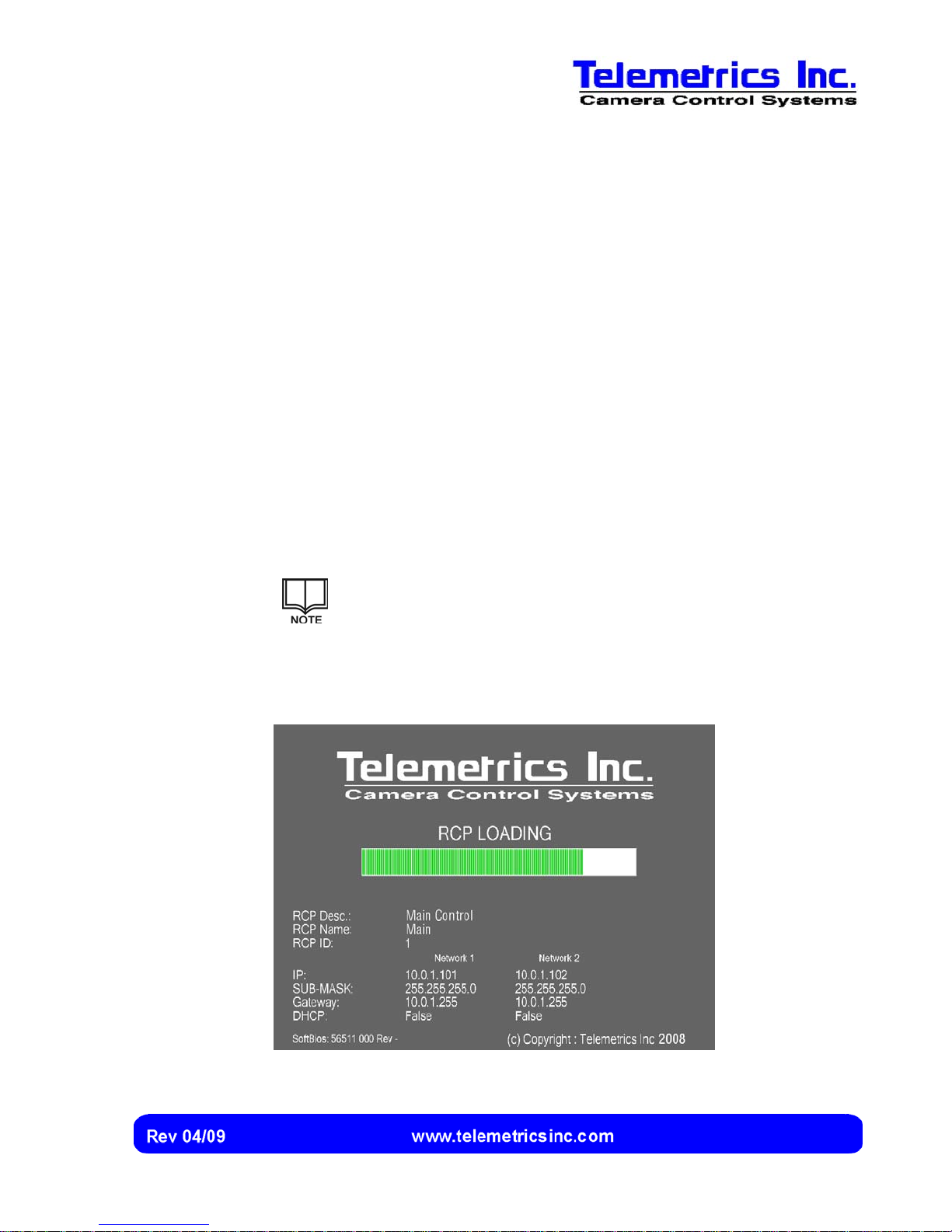
1. Place the main power switch in the ON position, then press the power button
at the bottom of the touch screen. The system initializes, and the RCP
Loading screen is momentarily displayed (Figure 23).
The main power switch can be left on, if desired. The screen saver
is displayed whenever the system is inactive for a specified period
of time. See page 26 for instructions to change the period of time
before the screen saver is displayed.
To cancel display of the screen saver, touch anywhere on the
screen.
Figure 23
RCP Loading
Screen
37
Page 40
Canon BU 45 Camera Control System User’s Manual
To display the RCP Configuration screen, select the progress bar
while the RCP Loading screen is displayed:
See page 25 for a description of the RCP Configuration screen and
instructions on configuring the RCP.
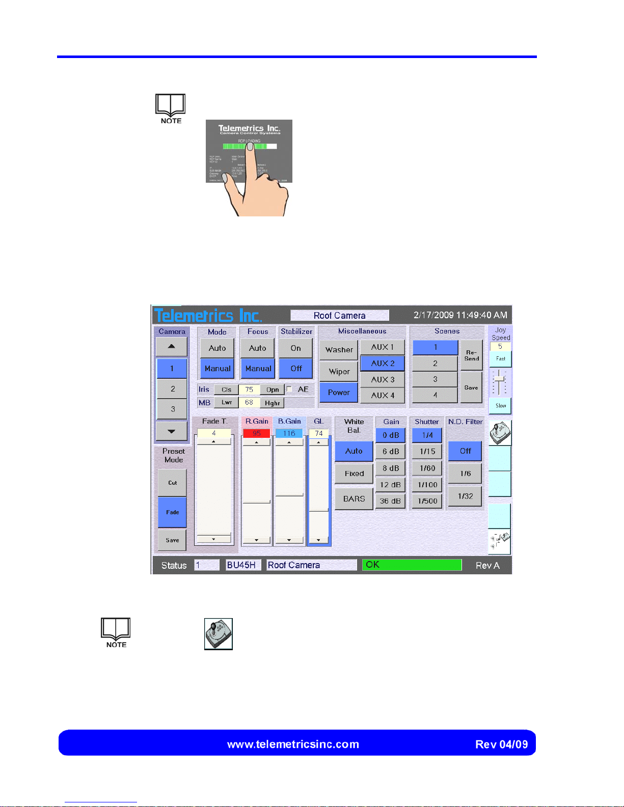
2. After the system has initialized and the software has loaded, the camera
control screen is displayed (Figure 23).
Figure 24 Camera Control Screen
Select the button to display backup RCP controls (joystick, zoom
control, focus control, and preset buttons) in place of the camera settings.
Other elements of the camera control screen are unchanged.
38
Page 41
Selecting a Camera
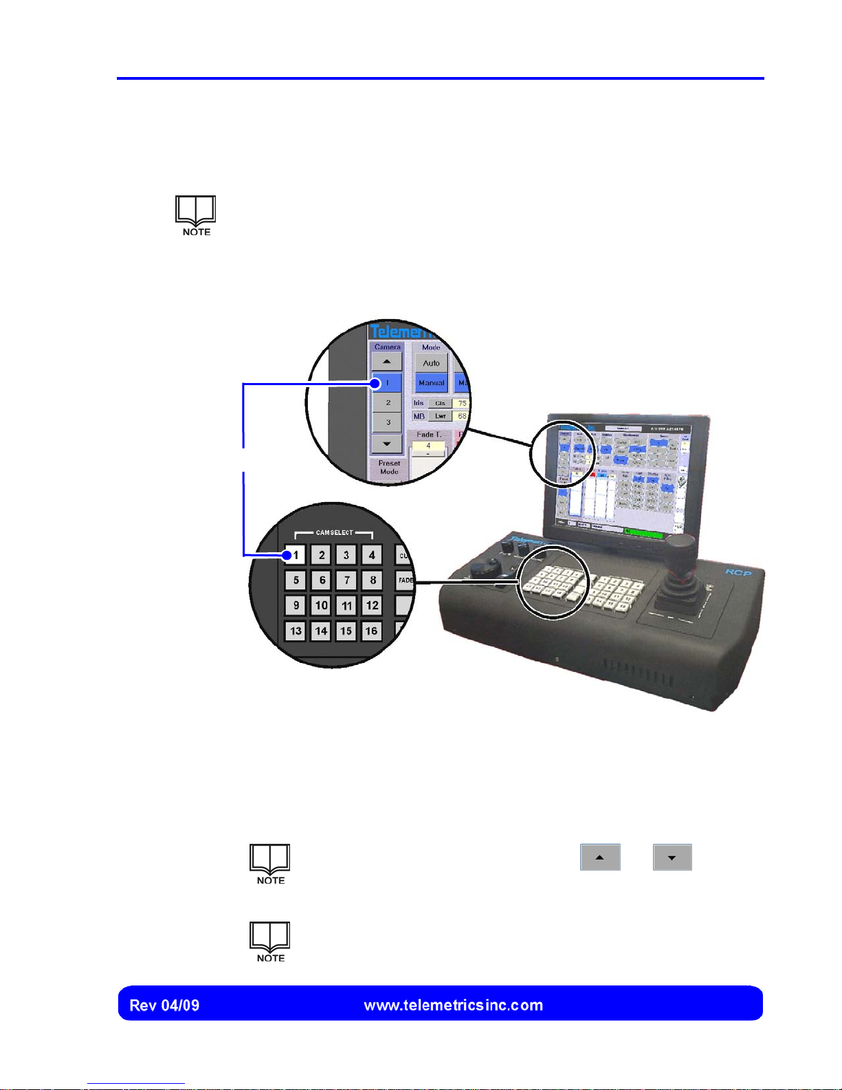
Camera selection buttons are located on the RCP and on the touch screen (Figure 25).
The button for the currently selected camera is illuminated on the RCP and
highlighted on the touch screen. The number and description of the currently
selected camera are also displayed on the touch screen (see page 10).
Camera assignments and descriptions are specified during Camera
Configuration (see page 28).
Selected Camera
Operation
Figure 25 Camera Selection Buttons
1. Press (on the RCP) or select (on the touch screen) the button for the camera
to be selected. The button for that camera is illuminated on the RCP case,
and the corresponding button is highlighted on the touch screen.
When using the touch screen, use the and scroll
arrows to display buttons for all of the cameras.
Check the power button (page 49) after selecting a camera to be
sure that power for that camera is switched on.
39
Page 42
Canon BU 45 Camera Control System User’s Manual
Controlling Pan, Tilt, Zoom, and Focus
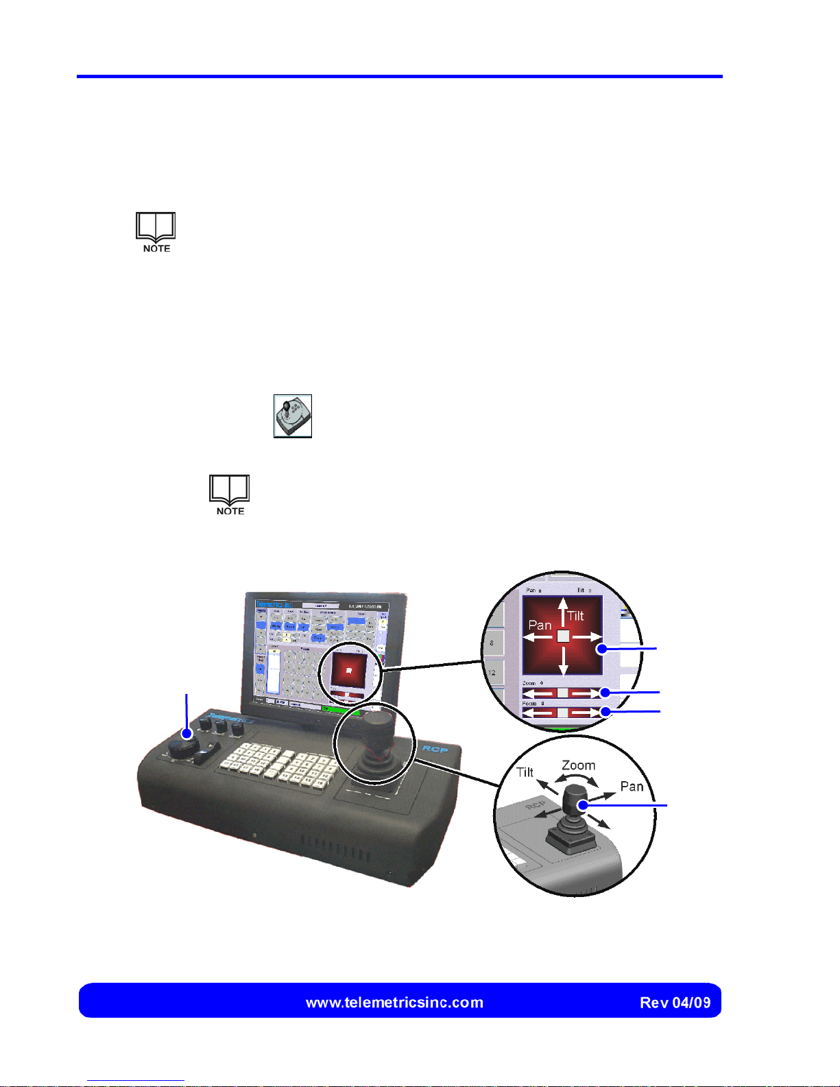
Pan, tilt, and zoom are controlled using the RCP joystick. Focus is controlled using the
RCP focus wheel (Figure 26).
Focus control is disabled when the Automatic focus mode is specified for a
camera. See page 47 for details.
Displaying Backup Controls and Digital Readings
If needed, backup controls with digital readings for the current pan, tilt, zoom, and focus
settings can be displayed on the touch screen. The controls can be used instead of the
joystick and focus wheel (Figure 26).
1. Select the
control, focus control, and preset buttons) in place of the camera settings.
Focus Wheel
button to display the backup RCP controls (joystick, zoom
The digital readings and positions of the backup RCP controls on
the touch screen correspond to the current pan, tilt, zoom, and
focus setting for the selected camera.
Pan/Tilt
Zoom
Focus
Joystick
Figure 26 Pan, Tilt, Zoom, and Focus Controls
40
Page 43
Operation
Controlling Pan, Tilt, and Zoom Using the Joystick
1. Move the joystick left to pan the camera housing to the left, or move the
joystick right to pan the camera housing to the right.
2. Move the joystick forward to tilt the camera housing down, or move the
joystick back to tilt the camera housing up.
3. Rotate the upper portion of the joystick clockwise to increase the
magnification, or rotate it counter-clockwise to decrease the magnification.
Adjusting the Joystick Speed
The joystick speed can be changed so that pan, tilt, and zoom change more rapidly or
more slowly when the joystick is moved or rotated.
The speed at which pan, tilt, and focus change is proportional to the
deflection that is applied to the joystick. At the highest joystick speed setting
(7), pan and tilt change 30 degrees per second at full deflection and 15
degrees per second at half deflection.
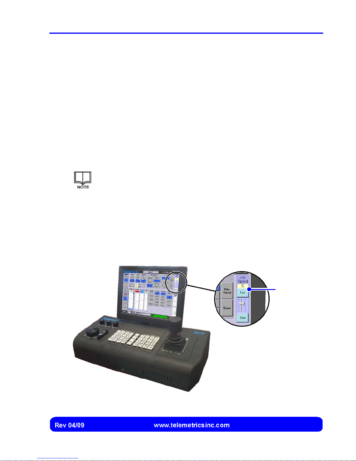
The current speed setting and the controls to change the speed are always displayed on
the Camera Control screen (Figure 27).
1. Select the Fast button to increase the speed by one increment, or select the
Slow button to decrease the speed by one increment. Alternately, select the
slider bar and drag it up (to increase the speed) or down (to decrease the
speed) one or more increments.
Current Speed
Setting
Figure 27 Joystick Speed Setting and Controls to Change the Speed
41
Page 44
Canon BU 45 Camera Control System User’s Manual
Controlling Focus Using the Focus Wheel
1. Rotate the focus wheel in the clockwise direction to focus on objects that are
nearer, or rotate the focus wheel in the counter-clockwise direction to focus
on objects that are more distant.
Controlling Pan, Tilt, Zoom, and Focus Using the Backup RCP Controls
1. (If needed) Select the button to display the backup RCP controls.
2. Drag the pan and tilt button left to pan the camera housing to the left, or drag
the pan and tilt button right to pan the camera housing to the right.
3. Drag the pan and tilt button up to tilt the camera housing down, or drag the
pan and tilt button down to tilt the camera housing up.
4. Drag the zoom button left to decrease the magnification, or drag the zoom
button right to increase the magnification.
5. Drag the focus button left to focus on objects that are nearer, or drag the
zoom button right to focus on objects that are more distant.
42
Page 45
Capturing and Recalling Presets
Presets are used to store the pan, tilt, zoom, and focus settings for a particular shot.
Sixteen preset shots can be stored and recalled for each camera.
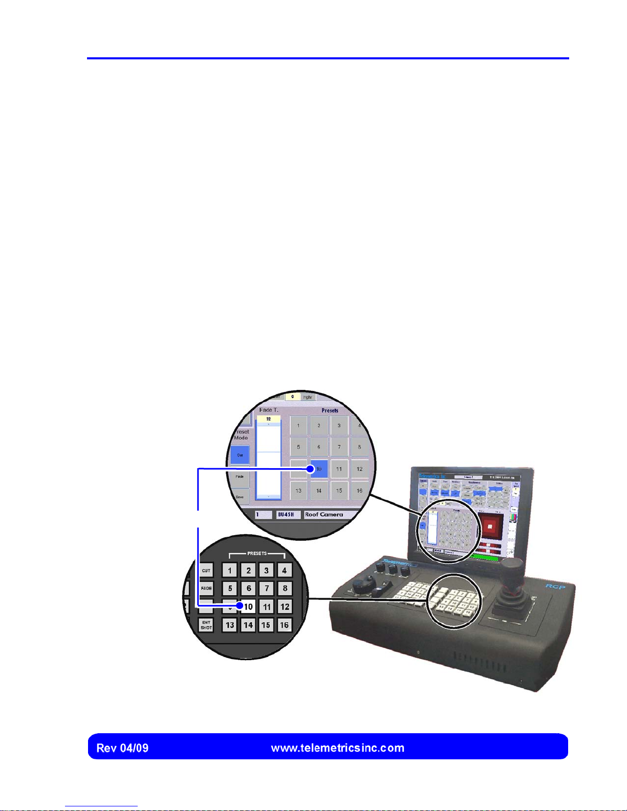
Buttons for saving and recalling a preset shot are located on the RCP and are also
included in the group of backup controls that can be displayed on the touch screen.
If a preset shot is currently selected, the button for the preset shot is illuminated on the
RCP and highlighted on the touch screen (Figure 28).
Capturing a Preset
1. Select the camera, and adjust the pan, tilt, zoom, and focus for the shot.
2. Press the ENT SHOT button on the RCP, or select either Save button on the
touch screen.
3. Press (or select, if using the touch screen backup controls) the Preset
number button that you wish to assign to the shot for the selected camera.
The shot will now be recalled whenever that camera is selected and that
button is pressed (or selected).
Operation
Selected Shot
Figure 28 Preset Buttons
43
Page 46
Canon BU 45 Camera Control System User’s Manual
Recalling a Preset Shot
1. Press (or select, if using the touch screen backup controls) the number button
that is assigned to the desired shot for the selected camera. The pan, tilt,
zoom, and focus settings are automatically changed to reproduce the preset
shot.
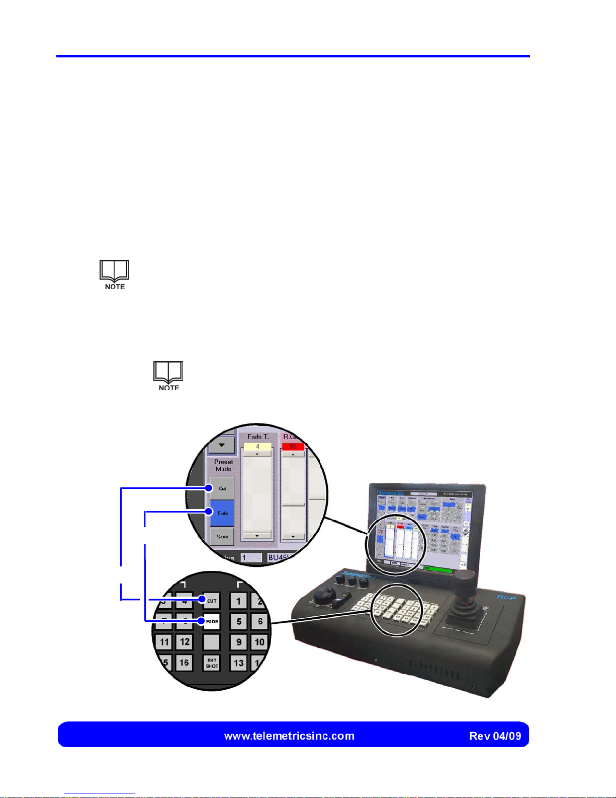
Cutting vs. Fading to Preset Shots
When a preset shot is selected, the transition to that shot can either be gradual (a fade)
or instantaneous (a cut). The manner in which transitions are made (the preset mode)
for all cameras is controlled by the Cut and Fade buttons on the RCP and touch screen.
The Cut and Fade buttons on the RCP and touch screen are redundant
(either can be used) and are illuminated (on the RCP) or highlighted (on the
touch screen) whenever the corresponding preset mode is selected.
1. Press (or select, if using the touch screen) the Cut button for instantaneous
transitions to a preset shot. Press (or select, if using the touch screen) the
Fade button for gradual transitions to a preset shot.
Cut Button
Fade Button
The preset mode is saved until changed by the operator. If the
Fade preset mode is selected, the transition time (from 3 seconds
to 47 seconds) can be specified (see the following section).
Figure 29 Cut and Fade Controls for Preset Shots
44
Page 47
Operation
r
r
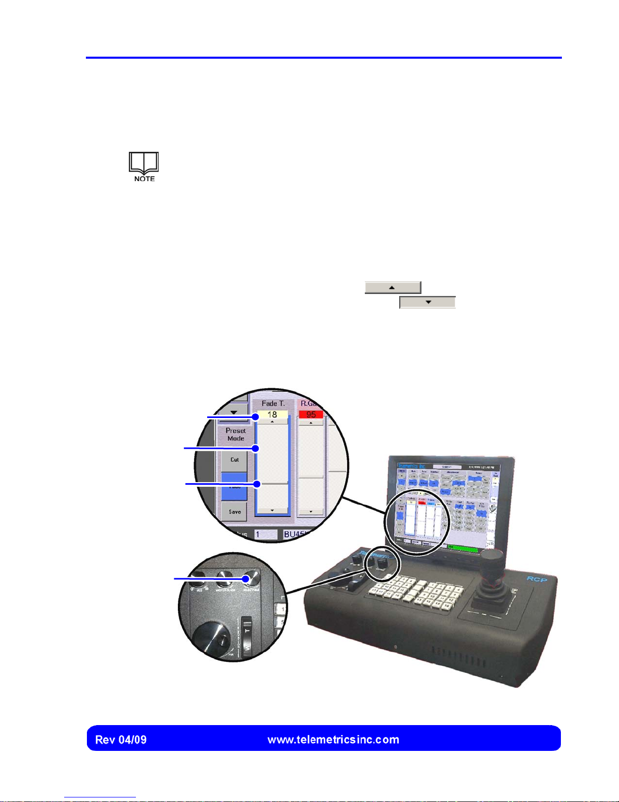
Setting the Fade Time
The fade transition time (from 3 seconds to 47 seconds) can be set using the fade time
controls on the touch screen or the selectable knob on the RCP (Figure 30).
The fade time setting (in seconds) is displayed at the top of the fade time
control. The fade time setting is saved until it is changed.
1. Select anywhere on the fade time control. A highlighted border is displayed,
indicating the fade time control is now linked to the selectable knob on the
RCP (Figure 30).
2. Using the slider: Select the fade time slider and drag it up (to increase the
fade time) or down (to decrease the fade time).
Current Fade
Time Setting
Highlighted
Borde
Fade Time
Slide
Selectable
Knob
Using the scroll buttons: Select the
time in one-second increments, or select the
button to increase the fade
button to decrease
the fade time in one-second increments.
Using the selectable knob on the RCP: Rotate the selectable knob
clockwise to increase fade time, or rotate the selectable knob counterclockwise to decrease fade time.
Figure 30 Fade Time Controls on the Touch Screen and RCP
45
Page 48
Canon BU 45 Camera Control System User’s Manual
r
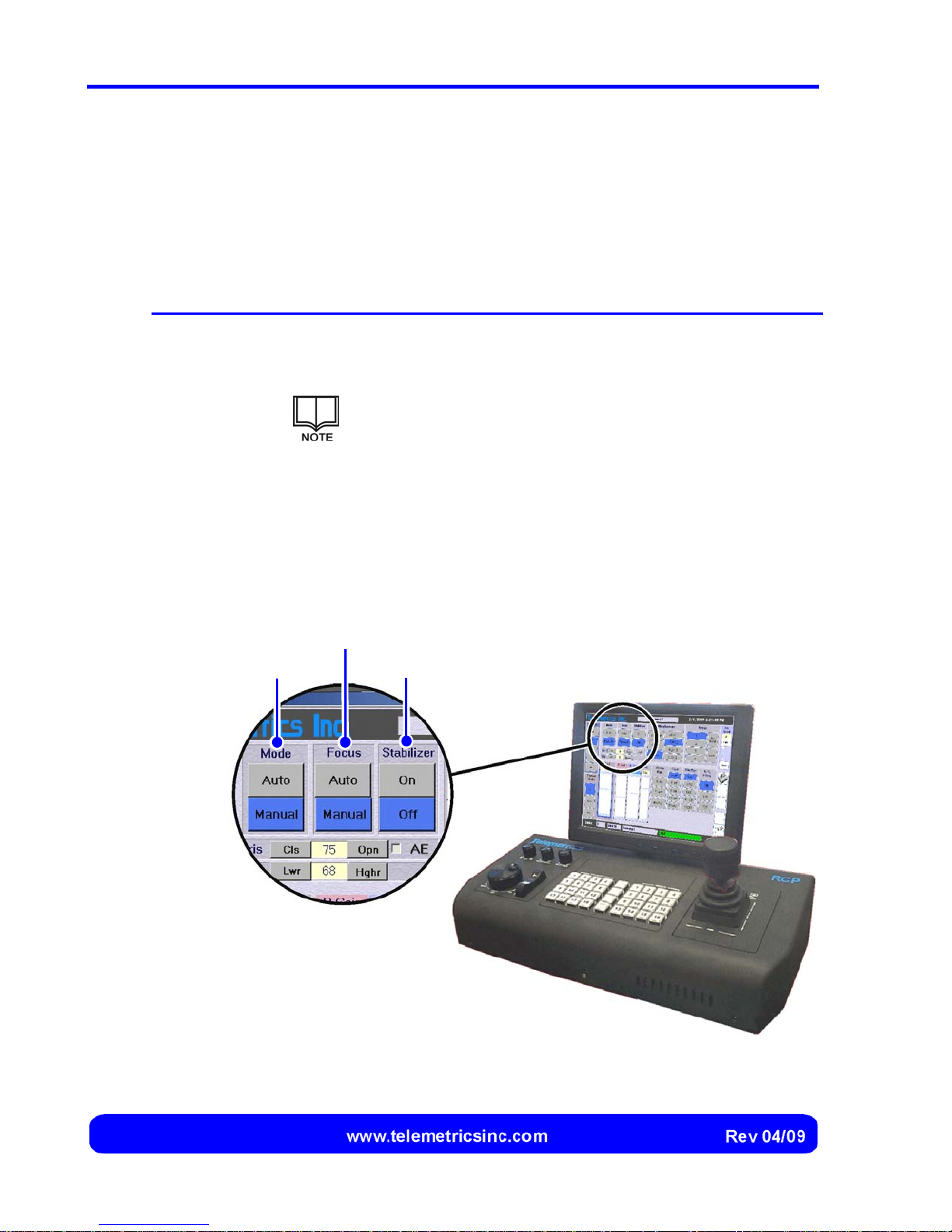
Specifying Camera Mode, Focus Mode, and Image Stabilizer
Camera Mode
The camera mode (Automatic vs. Manual) determines whether iris, master black, and
camera settings for the selected camera are controlled by the camera or by the operator:
Camera Mode Description
Automatic Specifies that iris, master black, and camera settings (see page 52)
are automatically controlled by the camera. Controls for camera
settings are disabled (read-only) whenever the camera is selected.
Manual
1. Select the Manual button under Mode (Figure 31) to specify the manual
mode, or select the Auto button under Mode to specify the automatic mode.
The selected mode is highlighted and saved for that camera.
Camera Mode
Specifies that iris, master black, and camera settings (see page 52)
are controlled by the operator. Controls for camera settings are
enabled whenever the camera is selected.
Focus Mode
Only the iris is automatically controlled when the AE iris
mode is selected for that camera (see page 51).
Image Stabilize
Figure 31 Controls for Camera Mode, Focus Mode, and Image Stabilizer
46
Page 49

Operation
Focus Mode
The focus mode (Automatic vs. Manual) determines whether focus for the selected
camera is controlled by the camera or by the operator:
Focus Mode Description
Automatic Specifies that focus is automatically controlled by the camera. The
focus wheel and the backup focus control on the touch screen are
disabled whenever the camera is selected.
Manual Specifies that focus is manually controlled by the operator. The focus
wheel and the backup focus control on the touch screen are enabled
whenever the camera is selected.
1. Select the Manual button under Focus (Figure 31) to specify the manual
mode, or select the Auto button under Focus to specify the automatic mode.
The selected mode is highlighted and saved for that camera.
Image Stabilizer
The image stabilizer mode (On vs. Off) determines whether the image stabilizer is
used when a camera is selected.
1. Select the On button under Stabilizer (Figure 31) to turn the image stabilizer
on, or select the Off button under Stabilizer to turn the image stabilizer off.
The selected mode is highlighted and saved for that camera.
47
Page 50
Canon BU 45 Camera Control System User’s Manual
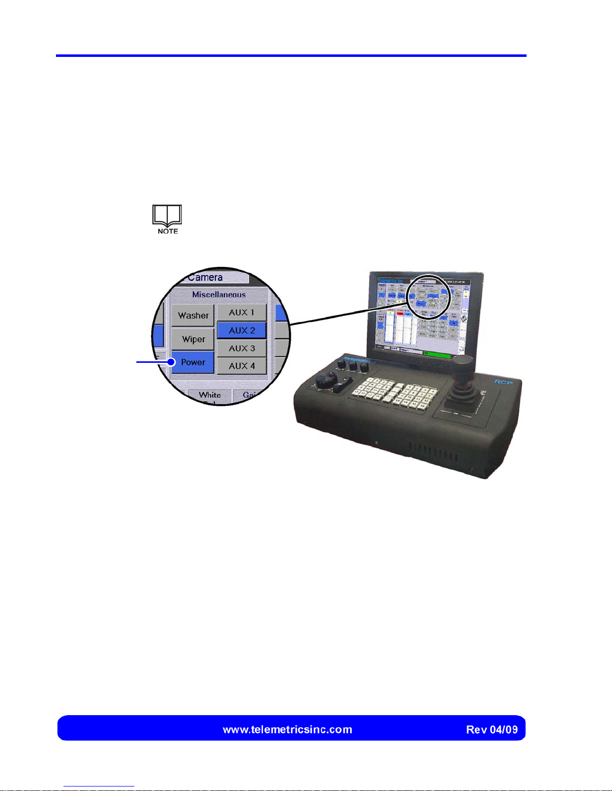
Switching Camera Power On or Off
To conserve camera life, power to the camera can be switched off when it is not in use.
Power to the housing for that camera, including the pan and tilt mechanism, is not
affected when camera power is turned oo or off. .
1. Select the Power button (Figure 32) to switch the camera power off (if it is
on) or on (if it is off) for the selected camera.
The Power button is included in the group of miscellaneous
controls. The Power button acts as a toggle and is highlighted
(darkened) while the camera power is switched on.
Camera
Power Button
Figure 32 Camera Power Control
48
Page 51
Using the Washer, Wiper, and Auxiliary Controls
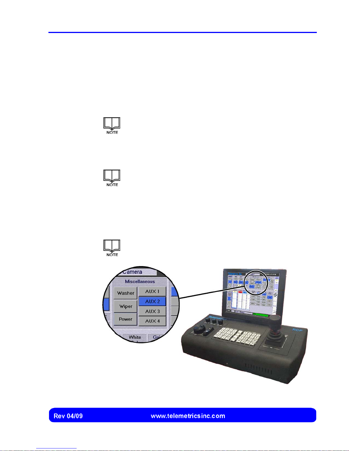
The Wiper, Washer, and auxiliary (AUX) controls are included in the group of
miscellaneous controls (Figure 33):
Washer
1. Select the Washer button to initiate a wash cycle for the selected camera.
The Washer button directs a short stream of washing fluid to the
outer surface of the lens port whenever it is selected.
Wiper
1. Select the Wiper button to initiate a wiping cycle for the selected camera.
The Wiper button operates the lens port wiper blade for a short
period of time whenever it is selected.
Operation
Auxiliary (AUX 1 to AUX 4)
1. Select the AUX 1, AUX 2, AUX 3, or AUX 4, button to switch the
corresponding auxiliary circuit (lights, for example) on (if it is off) or off (if it is
on) for the selected camera.
The AUX 1, AUX 2, AUX 3, and AUX 4 buttons act as a toggle and
are highlighted (darkened) while the corresponding circuit is closed.
Figure 33 Miscellaneous Controls
49
Page 52
Canon BU 45 Camera Control System User’s Manual
Adjusting Iris and Master Black Settings
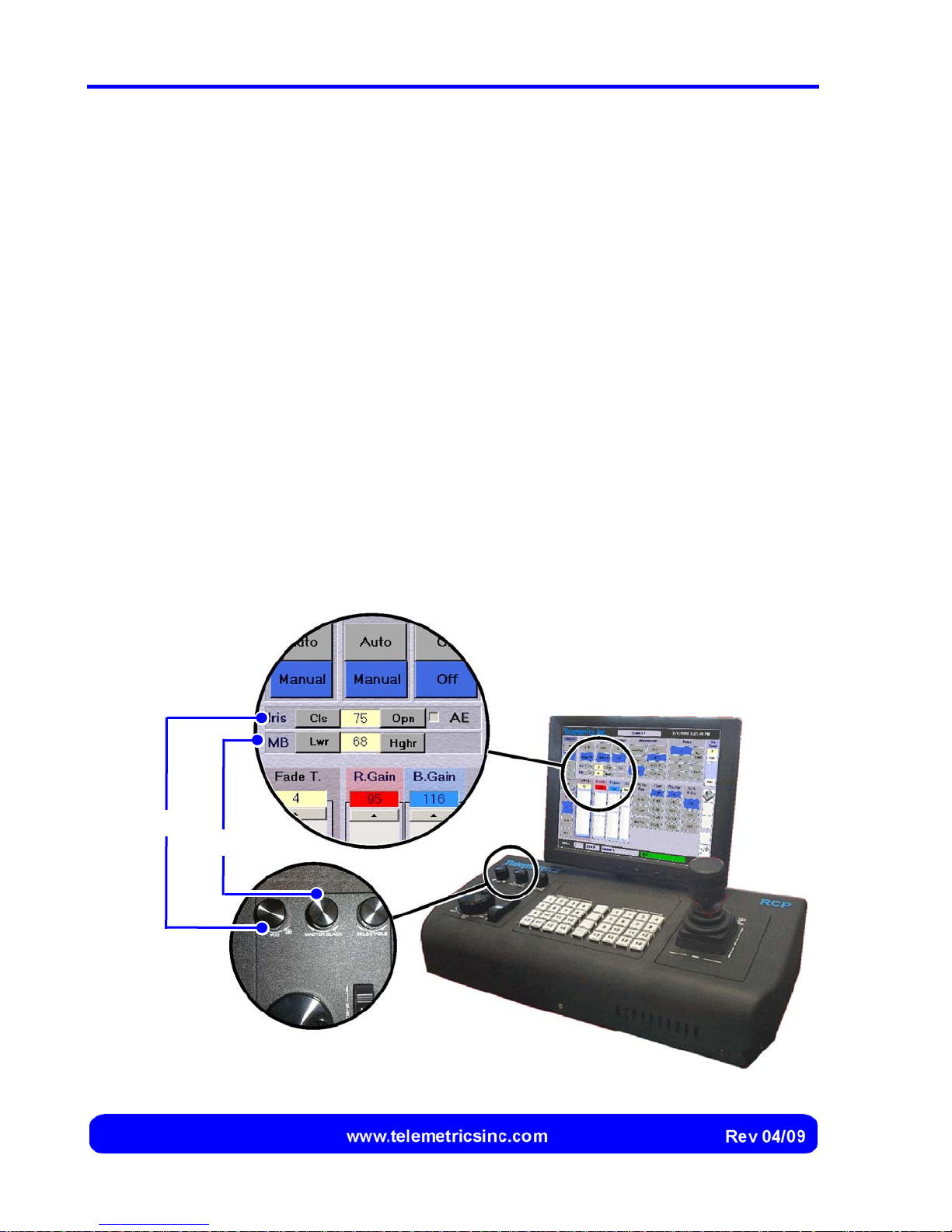
Settings for iris and master black (MB) are controlled using the Iris and Master Black
knobs on the RCP or the Iris and MB buttons on the touch screen (Figure 34).
Digital values for iris and master black settings are displayed on the touch screen.
Adjusting the Iris Setting
1. Rotate the Iris knob clockwise to open the lens, or rotate the knob counter-
clockwise to close the lens.
2. Alternately, select the Open button on the touch screen to open the lens one
increment, or select the Cls button to close the lens one increment.
Adjusting the Master Black Setting
1. Rotate the Master Black knob clockwise to increase the black level, or rotate
the knob counter-clockwise to increase the black level.
Iris
2. Alternately, select the Hghr button on the touch screen to increase the black
level, or select the Lwr button to decrease the black level.
Master Black
Figure 34 Iris and Master Black Controls
50
Page 53
Operation
Limiting Automatic Camera Mode to Automatic Exposure (Iris Control)
When Automatic is selected for camera mode, iris, master black, and camera settings
can be automatically controlled by the camera (see page 46).
If desired, the automatic mode of camera operation can be limited to automatic exposure
(iris control) only:
1. Select the Auto button under Mode to specify the automatic mode for the
selected camera and enable the Automatic Exposure (AE) check box.
The AE check box is disabled (read-only) whenever the manual
mode is selected.
2. Select the AE check box to insert a check mark and limit he automatic mode
of camera operation to iris control only.
The AE check box acts as a toggle. Select the check box again
to remove the check mark and specify that iris, master black, and
camera settings are automatically controlled when the selected
camera is in the automatic mode.
51
Page 54
Canon BU 45 Camera Control System User’s Manual
r
Adjusting Camera Settings
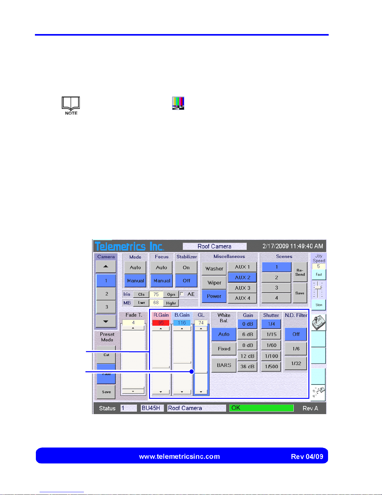
Camera setting controls and buttons are displayed on the lower portion of the touch
screen by default whenever the RCP is switched on (Figure 35).
Select the camera control button If the backup RCP controls are
displayed instead of the camera settings on the lower portion of the touch
screen.
Current settings of the R. Gain, B. Gain, and GL controls are shown as digital readings,
and currently selected White Bal., Gain, Shutter, and N.D. Filter buttons are
highlighted (darkened).
The camera settings are enabled whenever the Manual mode of camera operation is
specified for the selected camera. If the Automatic mode is selected, the camera
settings are disabled (read-only).
A highlighted border is displayed around the R. Gain, B. Gain, or GL controls whenever
they are selected (Figure 35). The corresponding setting can then be adjusted using
either the control on the touch screen or the Selectable knob on the RCP.
Camera Settings
Highlighted
Borde
Figure 35 Camera Settings
52
Page 55
Operation
Displaying Camera Settings Instead of RCP Backup Controls
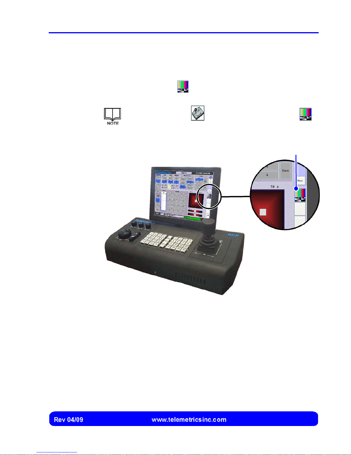
If the RCP backup controls are displayed on the touch screen (Figure 36), the camera
settings are hidden and cannot be used.
1. Select the camera controls
the backup RCP controls.
The backup controls button is displayed instead of the
button whenever the camera settings are displayed.
button to display camera settings instead of
Camera Controls
Button
Figure 36 Displaying Camera Settings Instead of the Backup Controls
53
Page 56
Canon BU 45 Camera Control System User’s Manual
r
Adjusting the Red Gain Setting
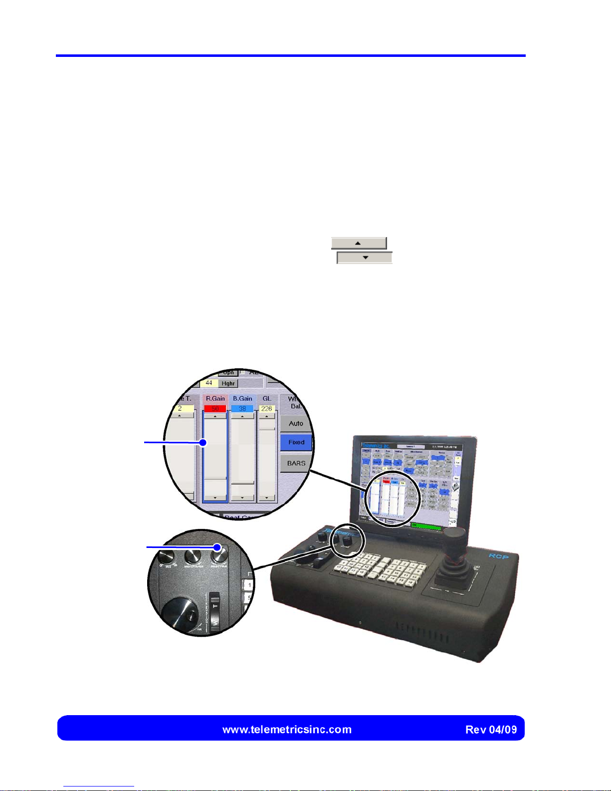
The R. Gain control is used to increase or decrease red gain (the intensity of red colors)
during color correction.
1. Select anywhere on the R. Gain control. A highlighted border is displayed,
indicating the red gain control is now linked to the Selectable knob on the
RCP (Figure 37).
2. Using the slider: Select the R. Gain slider and drag it up (to increase the red
gain) or down (to decrease the red gain).
Highlighted
Borde
Using the scroll buttons: Select the
gain in single increments, or select the
button to increase the red
button to decrease the red
gain in single increments.
Using the selectable knob on the RCP: Rotate the selectable knob
clockwise to increase red gain, or rotate the selectable knob counterclockwise to decrease red gain.
Selectable
Knob
Figure 37 Adjusting the Red Gain Setting
54
Page 57
Operation
Adjusting the Blue Gain Setting
The B. Gain control is used to increase or decrease blue gain (the intensity of blue colors)
during color correction.
1. Select anywhere on the B. Gain control. A highlighted border is displayed,
indicating the blue gain control is now linked to the Selectable knob on the
RCP (Figure 37).
2. Using the slider: Select the B. Gain slider and drag it up (to increase the
blue gain) or down (to decrease the blue gain).
Using the scroll buttons: Select the
gain in single increments, or select the
blue gain in single increments.
Using the selectable knob on the RCP: Rotate the selectable knob
clockwise to increase blue gain, or rotate the selectable knob counterclockwise to decrease blue gain.
button to increase the blue
button to decrease the
Adjusting the Genlock Setting
The GL control is used to adjust the timing of the camera so that it is synchronized with
other cameras.
1. Select anywhere on the GL control. A highlighted border is displayed,
indicating the Genlock control is now linked to the Selectable knob on the
RCP (Figure 37).
2. Using the slider: Select the GL slider and drag it up (to increase the
Genlock value) or down (to decrease the Genlock value).
Using the scroll buttons: Select the
Genlock value in single increments, or select the
decrease the Genlock value in single increments.
button to increase the
button to
Using the selectable knob on the RCP: Rotate the selectable knob
clockwise to increase the Genlock value, or rotate the selectable knob
counter-clockwise to decrease the Genlock value.
55
Page 58
Canon BU 45 Camera Control System User’s Manual
Specifying the White Balance Setting
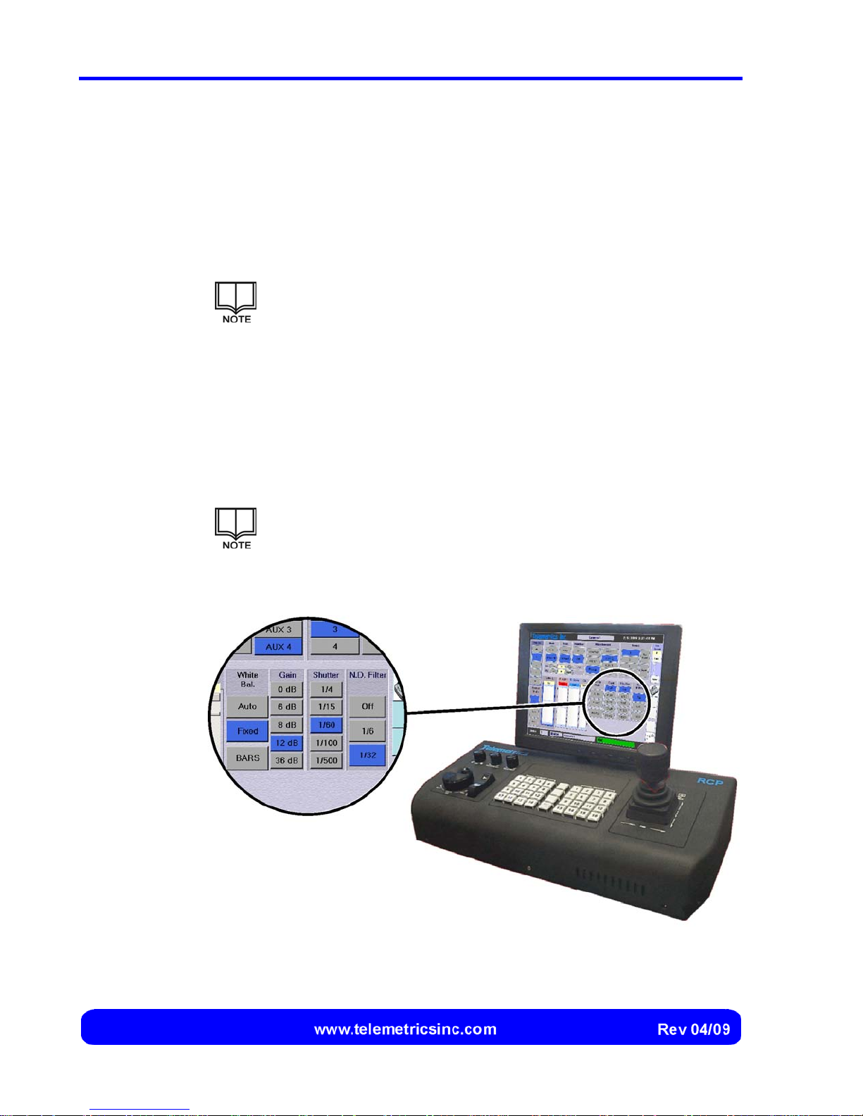
The White Bal. buttons (Figure 38) allow the operator to choose between two methods
for performing white balance.
1. Select the Auto button to allow the camera to automatically adjust white
balance, or select the Fixed button to use fixed default settings for white
balance. The selected mode is highlighted and saved for that camera.
Either the Auto or Fixed button will be selected at any time.
Generating Color Bars
The selected camera can be directed to generate and display color bars instead of an
image. The color bars will continue to be generated until cancelled.
1. Select the BARS button to generate color bars from the camera, or (if color
bars are currently being generated) select the BARS button to cancel the
color bars.
The BARS button acts as a toggle and is highlighted (darkened)
whenever the selected camera is generating color bars.
Figure 38 Buttons for White Balance and Other Camera Settings
56
Page 59
Operation
Changing the Gain Setting
The Gain buttons (Figure 38) allow the operator to change the sensitivity of the camera to
optimize image quality vs. noise under different lighting conditions.
1. Select the corresponding gain button (0 dB, 6 dB, 8 dB, 12 dB, or 36 dB) to
set that gain level. The selected gain level is highlighted and saved for that
camera.
Gain is usually set at 0. One of the gain buttons will always be
selected.
Changing the Shutter Setting
The Shutter buttons (Figure 38) allow the operator to change the shutter speed of the
camera to compensate for rapidly moving objects and lighting.
1. Select the corresponding shutter button (1/4, 1/15, 1/60, 1/100, or 1/500) to
select that shutter speed. The selected shutter speed is highlighted and
saved for that camera.
One of the shutter buttons will always be selected.
Specifying Use of a Neutral Density Filter
The N.D. Filter buttons (Figure 38) allow the operator to specify whether a neutral
density filter is positioned over the lens to prevent over-exposure when a view is overly
bright.
One of the N.D. Filter buttons (Off, 1/6, or 1/32) will always be selected.
1. Select the corresponding neutral density filter button (1/6 or 1/32) to position
that neutral density filter over the lens. The neutral density filter selection is
highlighted and saved for that camera.
2. Select the Off button to operate the camera without a filter positioned over the
lens.
57
Page 60
Canon BU 45 Camera Control System User’s Manual
Saving and Recalling Camera Settings (Scenes)
Scenes are used to store the camera settings (see page 52) that have been optimized
for particular lighting. Four scenes can be stored and recalled for each camera.
Scenes can only be saved or recalled when the camera is in the Manual
mode of operation (see page 46).
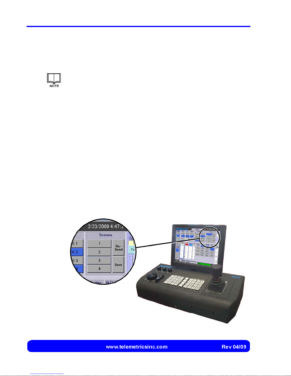
Buttons for saving and recalling a scene are located on the upper portion of the touch
screen. If a scene is currently selected, the button for the scene is highlighted on the
touch screen (Figure 28).
Capturing a Scene
1. Select the camera, ensure that the lighting is typical for the scene, and then
adjust the camera settings.
2. Select either Save button on the touch screen.
3. Select the Scene number button that you wish to assign to the scene for the
selected camera. The camera settings will now be recalled for that camera
whenever the camera is selected and that scene button is selected.
Recalling a Scene
1. Select the Scene button with the number that is assigned to the desired
scene for the selected camera. The camera settings are automatically
changed.
Figure 39 Scene Buttons
58
Page 61
Re- Sending a Scene
If power to a camera is switched off (page 48), the scene settings are not retained in the
camera. used to store the camera settings (see page 52) that have been optimized for
particular lighting. Four scenes can be stored and recalled for each camera.
Shutdown
Switching the Power Off
The main power switch is located at the rear of the Telemetrics Remote Control Panel
(RCP) (see Figure Figure 11 on page 21).
Operation
1. (If necessary) Select the Scene button with the number that is assigned to the
desired scene for the selected camera to highlight the button.
2. Select the Re-send button. The camera settings are automatically restored.
1. Place the main power switch in the OFF position.
Power can be switched off at any time.
The power switch can be left on. A screen saver is displayed
whenever the system is inactive for the specified period of time.
59
Page 62

Canon BU 45 Camera Control System User’s Manual
This page intentionally left blank.
60
Page 63
Troubleshooting
The Telemetric Remote Control Panel (RCP) is almost completely self-monitoring and
has no user serviceable parts.
Risk of electric shock. The RCP has no user serviceable parts. It must only
be serviced by qualified personnel.
Risk of electric shock. Never disassemble the RCP.
Troubleshooting Chart
In the event that a problem occurs during operation of the system, follow the
troubleshooting procedures outlined below:
Problem Probable Cause Corrective Action
The RCP does not
operate at all
2. The power cord is
3. The power receptacle
4. The fuse is blown. 4. Replace the fuse (page 61).
5. A component in the
1. The RCP power switch
is turned off.
disconnected.
is faulty.
RCP has failed.
1. Turn on the RCP power
switch.
2. Connect the RCP to a power
receptacle.
3. Connect the RCP to a
different power receptacle.
If the fuse continues to blow,
contact Telemetrics.
4. Contact your Telemetrics
representative for
assistance.
61
Page 64

Canon BU 45 Camera Control System User’s Manual
Problem Probable Cause Corrective Action
The RCP operates,
but the touch
screen is dark
2. The touch screen
4. A component in the
The RCP operates,
but one or more of
the RCP controls
do not work
1. The touch screen
power button was not
pressed during startup.
brightness is turned
down.
3. One or both touch
screen cables are
disconnected or
broken.
RCP or touch screen
has failed.
1. A component in the
RCP has failed.
1. Press the touch screen
power button.
2. Readjust the touch screen
brightness.
3. Connect or replace the touch
screen cables.
4. Contact your Telemetrics
representative for
assistance.
1. Contact your Telemetrics
representative for
assistance.
62
Page 65
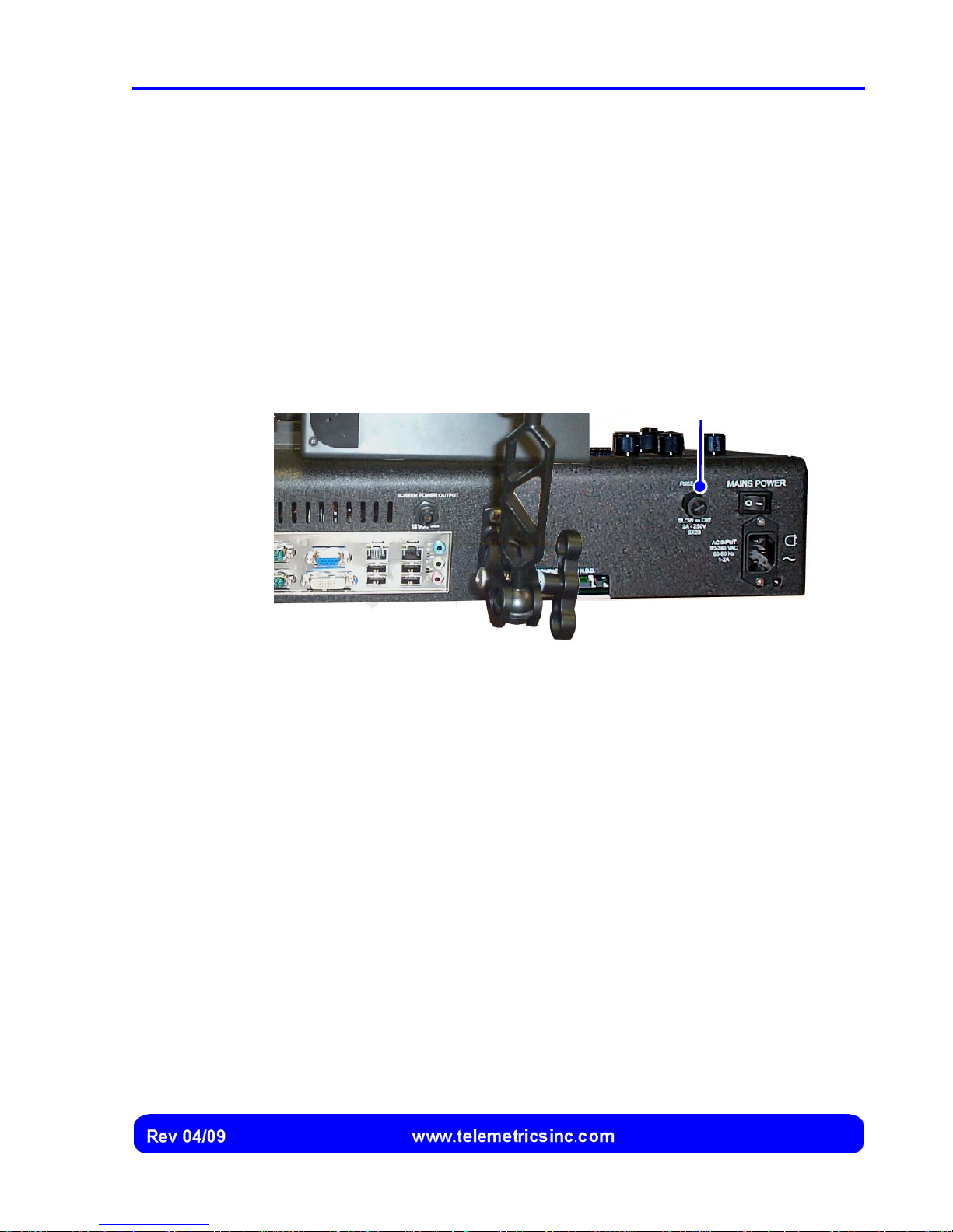
Replacing the RCP Fuse
A 2.0 amp 5 x 20 mm slow-blow fuse is used on the RCP.
1. Turn off the RCP power switch.
2. Loosen the fuse holder and remove the fuse (Figure 40).
3. Replace the fuse and fuse holder.
4. Turn on the RCP power switch.
Troubleshooting
Fuse Holder
Figure 40 Replacing the RCP Fuse
63
Page 66

Canon BU 45 Camera Control System User’s Manual
This page intentionally left blank.
64
Page 67

Index
assigning cameras...........................28
auxiliary controls..............................49
backup controls
displaying.............................12, 40
blue gain ..........................................55
Camera Control screen..............10, 38
camera mode...................................46
camera power..................................48
camera settings................................52
master black.....................................50
color bars.........................................56
compact flash card.....................13, 33
configuration ....................................13
controlling focus...............................40
controlling pan and tilt......................40
controlling zoom...............................40
copying files.....................................34
Device Server DS-4.....................7, 15
digital readings
displaying...................................40
Enhanced Write Filter ......................13
Ethernet connection.........................15
EWF.................................................13
EWF tools ........................................33
fade time..........................................45
focus ..........................................40, 42
focus mode ......................................47
fuse removal and replacement.........63
gain setting.......................................57
Genlock............................................55
hub...................................................23
image stabilizer................................47
installing the RCP............................17
attaching the touch screen.........18
connecting keyboard or mouse.. 20
connecting the touch screen...... 19
connecting to a hub or switch.... 23
connecting to a power source.... 21
connecting to cameras...............22
desktop vs. rack-mounted.......... 17
iris....................................................50
joystick...........................................8, 9
operation...................................... 9
joystick speed..................................41
keyboard..........................................25
knobs.............................................8, 9
focus wheel.................................. 9
Iris knob....................................... 9
Master Black knob....................... 9
User Selectable knob.............9, 11
locating components........................ 15
Device Server DS-4................... 16
hub or switch.............................. 16
Remote Control Panel (RCP) .... 15
network connection.......................... 14
neutral density filter ......................... 57
on-screen keyboard......................... 25
operating system.............................13
operation
zoomn........................................ 41
pan and tilt.......................................40
preset mode..................................... 44
65
Page 68

Canon BU 45 Camera Control System User’s Manual
presets
capturing.....................................43
cutting vs. fading ........................44
recalling......................................44
proportional speed control................. 8
pushbuttons....................................... 8
RCP Configuration screen............... 24
displaying ...................................37
RCP hard drive................................ 33
RCP mounting configurations.......... 13
RCP power switch........................... 37
RCP screen saver........................... 37
RCP software.................................. 13
red gain ........................................... 54
re-start............................................. 32
rocker switch ..................................... 8
scenes............................................. 58
recalling......................................58
re-sending ..................................59
saving.........................................58
screen saver time............................ 27
selecting a camera.......................... 39
shut down........................................ 32
shutdown......................................... 59
shutter speed................................... 57
specifications ...................................14
starting the system...........................37
switch...............................................23
system configuration..................13, 24
assigning cameras.....................28
displaying a keyboard ................25
IP address..................................27
RCP ID.......................................26
RCP name and description........26
RCP network connection............27
runtime application.....................26
system overview ................................7
touch screen ......................................8
calibration...................................32
controls.......................................31
troubleshootings...............................61
updating software.............................33
user interface...................................10
backup controls..........................12
button and slider highlighting .....11
washer .............................................49
white balance...................................56
wiper ................................................49
zoom..........................................40, 41
66
 Loading...