

Page 1

APR.2000
HY8-53A2-00Z
COPYRIGHT © 2000 CANON INC. FACSIMILE BASIC2000 APR.2000 PRINTED IN JAPAN (IMPRIME AU JAPON)
FACSIMILE
FACSIMILE
BASIC
2000
REVISION 0
Page 2

Application
This manual has been issued by Canon Inc. to provide information necessary to self-study to technicians who service facsimile products. This manual covers all localities where the facsimile
products are sold. For this reason, there may be information in this manual that does not apply to
your locality.
The following paragraph does not apply to any countries where such provisions are inconsistent with local law.
Trademarks
The product names and company names described in this manual are the registered trademarks of
the individual companies.
Copyright
This manual is copyrighted with all rights reserved. Under the copyright laws, this manual may
not be copied, reproduced or translated into another language, in whole or in part, without the
written consent of Canon Inc.
Copyright © 2000 by Canon Inc.
CANON INC.
Office Imaging Products Technical Support Dept. 3
5-1 Hakusan 7-Chome, Toride-city, Ibaraki 302-8501, Japan
DTP System
All graphics in this manual were produced with Windows Macromedia FreeHand
®
8.0J
All documents in this manual and all page layouts were created with Windows Adobe Frame
Maker® 5.5J
Page 3

i
1
2
3
4
5
6
ït
çi
PREFACE
This manual describes the general technology and principles of CANON facsimile operation so
that those studying facsimiles for the first time and those already servicing facsimiles can gain a
further understanding of these equipment.
Chapters 1 and 2 describe an overview of telephony and facsimile operation. Chapter 3 onwards
describes the reading section, recording section, communications and electrics in more detail.
Those studying facsimiles for the first time should begin their studies with Chapters 1 and 2.
Those already servicing facsimiles or those who already understand facsimiles to a certain extent
may refer to chapters that meet their particular requirements.
This manual is made up of the following chapters:
Chapter 1: BASIC OF TELEPHONE
Chapter 2: GENERAL DESCRIPTION OF A FACSIMILE
Chapter 3: READING SECTION
Chapter 4: RECORDING SECTION
Chapter 5: G3 FACSIMILE COMMUNICATIONS
Chapter 6: FACSIMILE SYSTEM
APPENDIX
The appendix is followed by a glossary with supplementary explanations of technolog y that could
not be described in the main text. Refer to this glossary as necessary.
Words colored red in this document are explained in the “GLOSSARY” in the “APPENDIX” of
this document.
Page 4

ii
CONTENTS
PREFACE.........................................................................................i
CONTENTS.....................................................................................ii
CHAPTER 1 BASIC OF TELEPHONE
INTRODUCTION TO THE TELEPHONE.....................................1-2
Parts of the Telephone..............................................................1-2
Making a Call............................................................................1-3
How do you make a call?..........................................................1-4
Voice Frequencies Carried by the Telephone...........................1-4
STRUCTURE OF A TELEPHONE...............................................1-5
Transmitter (Microphone)..........................................................1-6
Receiver (Speaker)...................................................................1-7
Voice Circuit..............................................................................1-7
Hook Button..............................................................................1-8
Dial............................................................................................1-9
Bell (Speaker).........................................................................1-10
TYPES OF TELEPHONES.........................................................1-11
Dial Telephones......................................................................1-11
Pushbutton Telephones..........................................................1-11
Digital Telephones..................................................................1-12
CIRCUIT DIAGRAM IN THE TELEPHONE................................1-13
Dial Telephones......................................................................1-13
Pushbutton Telephone............................................................1-14
INTRODUCTION TO THE TELEPHONE NETWORK................1-15
Parts of a Telephone Network ................................................1-15
Basic Structure of a Telephone Network System ...................1-19
Nationwide Telephone Network (In case of Japan)................1-20
TELEPHONE EXCHANGES......................................................1-25
Types of Exchanges ...............................................................1-25
The Exchange.........................................................................1-26
CHAPTER 2 GENERAL DESCRIPTION OF A FACSIMILE
WHAT IS A “FACSIMILE?”...........................................................2-2
Established Rules of Communication.......................................2-2
Control Procedure.....................................................................2-2
Facsimile Groups......................................................................2-3
Page 5

iii
Telephone Lines.......................................................................2-3
Types of ITU-T Recommendations...........................................2-4
How Images are Transmitted ...................................................2-8
STRUCTURE OF A FACSIMILE................................................2-13
Reading Section .....................................................................2-15
Recording Section ..................................................................2-18
MODEM..................................................................................2-21
NCU board (Network Control Unit board)...............................2-22
System Control Section..........................................................2-22
THE FUTURE OF FACSIMILES................................................2-23
Color Facsimiles.....................................................................2-23
LAN-networked Facsimiles.....................................................2-23
Internet Facsimiles .................................................................2-24
CHAPTER 3 READING SECTION
INTRODUCTION..........................................................................3-2
READING METHODS..................................................................3-3
Sheet Reading Method.............................................................3-3
Book Reading Method..............................................................3-4
ADF Type .................................................................................3-4
CONTACT SENSOR..................................................................3-10
Structure of Contact Sensor ...................................................3-10
Features of Contact Sensor....................................................3-10
IMAGE DATA PROCESSOR.....................................................3-14
Various Image Data Processing............................................3-14
CHAPTER 4 RECORDING SECTION
INTRODUCTION..........................................................................4-2
IMAGE DATA PROCESSING SECTION.....................................4-3
Image Area Separation Processing, Smoothing Processing
and Selector .............................................................................4-4
Reproduction Ratio Processing Section...................................4-8
Ink Saving/Toner Saving ........................................................4-11
PAPER FEED SECTION ...........................................................4-12
Pickup Section........................................................................4-12
Feed/Eject Section .................................................................4-17
Detection of Recording Paper Jams.......................................4-19
PRINTING SECTION.................................................................4-24
LBP (LASER Beam Printer)....................................................4-24
Page 6

iv
Printing by LASER..................................................................4-24
Flow of Printing.......................................................................4-26
Video Control Section/Printer Engine Control Section............4-27
LASER/Scanner Section.........................................................4-32
Printing Process......................................................................4-34
Toner Cartridge.......................................................................4-46
BJ (Bubble Jet) Printer............................................................4-48
Printing by Bubbles.................................................................4-48
Printing Section.......................................................................4-50
Carriage Section.....................................................................4-51
Purge Unit...............................................................................4-56
BJ Cartridge............................................................................4-58
CHAPTER 5 G3 FACSIMILE COMMUNICATIONS
INTRODUCTION..........................................................................5-2
WHAT IS A “G3 FACSIMILE?”.....................................................5-2
G3 FACSIMILE IMAGE TRANSMISSION....................................5-3
Structure of Image Signals........................................................5-3
Transmission Time....................................................................5-5
CODING SCHEMES ....................................................................5-8
Why is Coding Necessary?.......................................................5-8
MH Coding Scheme (One-dimensional Coding Scheme).......5-10
MR Coding Scheme (Two-dimensional Coding Scheme).......5-17
MMR Coding Scheme.............................................................5-28
JBIG Image Compression Encoding Scheme.........................5-29
MODULATION METHOD...........................................................5-45
Modulation and Demodulation................................................5-45
Shift and Modulation Methods ................................................5-46
Modulation Methods up to 9600 bps.......................................5-47
High-speed MODEMs above 14400 bps ................................5-55
V.17 (V.33) MODEM Technology ...........................................5-55
V.34 MODEM Technology......................................................5-73
TRANSMISSION CONTROL PROCEDURES...........................5-89
Outline of Transmission Control Procedures..........................5-89
Signal Types...........................................................................5-90
Basic Transmission Control Procedure...................................5-91
Procedures for Performing Individual Page Control
(Q signals).............................................................................5-100
Training.................................................................................5-102
Method for Detecting Image Signal Transmission Errors .....5-104
Page 7

v
Option Signals ......................................................................5-106
Structure of Binary Signals...................................................5-107
Example of G3 Procedures ..................................................5-122
ECM Communications..........................................................5-123
CHAPTER 6 FACSIMILE SYSTEM
INTRODUCTION..........................................................................6-2
SCNT BOARD..............................................................................6-3
System Control Section............................................................6-3
Communications Control Section .............................................6-4
Reading Control Section...........................................................6-4
Printer Control Section .............................................................6-4
NCU BOARD................................................................................6-5
Off-hook Detection....................................................................6-6
Formation of DC Loop ..............................................................6-6
Detection of Calling Identification (CI) ......................................6-9
Line Signal Monitor.................................................................6-10
Dial Control.............................................................................6-11
2-wire/4-wire Conversion........................................................6-12
Protective Circuits...................................................................6-12
Telephone Connection Control...............................................6-14
Relay Operations....................................................................6-17
OPCNT BOARD.........................................................................6-18
Detection of Button Input........................................................6-18
LED Lighting Control ..............................................................6-21
Display Indication Control.......................................................6-21
FLOW OF IMAGE SIGNALS......................................................6-22
Transmission ..........................................................................6-22
Reception ...............................................................................6-23
POWER SUPPLY UNIT.............................................................6-24
Switching Regulator................................................................6-24
Configuration of Power Supply Unit on a Facsimile ...............6-31
G4CNT BOARD .........................................................................6-32
APPENDIX
TRANSMISSION LINES OF TELEPHONE LINES ..................... A-2
CHARACTERISTICS OF TELEPHONE LINE (ANALOG).......... A-4
Telephone Line Band .............................................................. A-4
Characteristics of Telephone Network Components ............... A-5
Page 8

vi
Factors of Telephone Line Deterioration..................................A-6
FACSIMILE COMMUNICATION NETWORK SERVICES &
MINIFAX (JAPAN ONLY).......................................................... A-10
F-NET ....................................................................................A-12
Minifax I (MF-I).......................................................................A-16
Minifax II (MF-II).....................................................................A-17
TELEPHONE LINE BAND & SIGNAL SPECTRUM..................A-19
S/N.............................................................................................A-20
POLARITY INVERSION ON EXCHANGE ................................A-21
FACTORS WHICH CAUSE DETERIORATION
IN QUALITY OF FACSIMILE TRANSMISSION........................ A-22
Usual Factors.........................................................................A-22
Unusual Factors ..................................................................... A-27
Echo....................................................................................... A-28
RATIO, dB, dBm & dBV.............................................................A-35
BINARY SIGNALS TABLE........................................................ A-39
MAKER CODES TABLE............................................................A-42
STANDARD DOCUMENT SIZES..............................................A-44
G3 FACSIMILE TRANSMISSION CONTROL PROCEDURES A-45
GLOSSARY...............................................................................A-67
INDEX............................................................................................I-1
Page 9

CHAPTER
1
1
2
3
4
5
6
ït
çi
1 BASIC OF TELEPHONE
1. INTRODUCTION TO THE TELEPHONE................................. 1-2
1.1 Parts of the Telephone .................................................... 1-2
1.2 Making a Call .................................................................. 1-3
1.3 How do you make a call? ................................................ 1-4
1.4 Voice Frequencies Carried by the Telephone.................. 1-4
2. STRUCTURE OF A TELEPHONE........................................... 1-5
2.1 Transmitter (Microphone) ................................................ 1-6
2.2 Receiver (Speaker) ......................................................... 1-7
2.3 Voice Circuit .................................................................... 1-7
2.4 Hook Button .................................................................... 1-8
2.5 Dial.................................................................................. 1-9
2.6 Bell (Speaker)................................................................ 1-10
3. TYPES OF TELEPHONES ....................................................1-11
3.1 Dial Telephones............................................................. 1-11
3.2 Pushbutton Telephones................................................. 1-11
3.3 Digital Telephones......................................................... 1-12
4. CIRCUIT DIAGRAM IN THE TELEPHONE ........................... 1-13
4.1 Dial Telephones............................................................. 1-13
4.2 Pushbutton Telephone................................................... 1-14
5. INTRODUCTION TO THE TELEPHONE NETWORK............ 1-15
5.1 Parts of a Telephone Network.......................................1-15
5.2 Basic Structure of a Telephone Network System.......... 1-19
5.3 Nationwide Telephone Network (In case of Japan)....... 1-20
6. TELEPHONE EXCHANGES.................................................. 1-25
6.1 Types of Exchanges......................................................1-25
6.2 The Exchange............................................................... 1-26
Page 10
BASIC OF TELEPHONE
1–2
1. INTRODUCTION TO THE TELEPHONE
You can’t transmit a document unless your facsimile and the receiving facsimile are connected over a telephone line. In this section, let’s learn about
the basics of telephones and telephone lines.
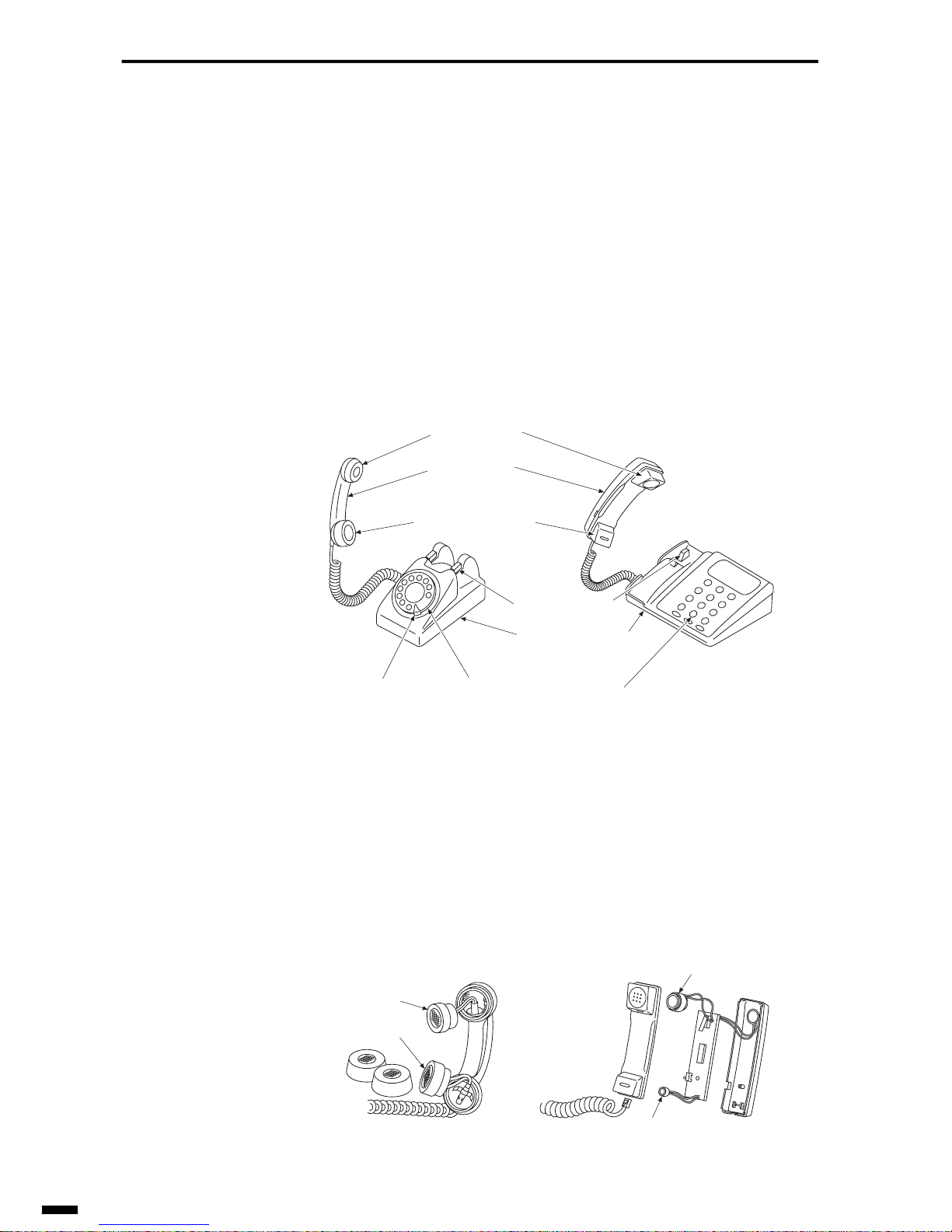
1.1 Parts of the Telephone
Very few people know the names of the parts of a telephone even though
they use it every day. Let’s learn the names of the parts on a telephone.
Fig. 1-1 Parts of the Telephone
What we generally refer to as the receiver was in fact the handset.
The “receiver” is the part that we hold against the ear on the handset.
Likewise, the part that we bring near our mouth on the handset is called the
transmitter.
Some people mistakenly refer to the handset as the receiver.
Fig. 1-2 Handset
(Receiver)
(Handset)
(Transmitter)
Hook button
Dial
Pushbuttons
Stopper
Telephone body
Receiver
Transmitter
Receiver
Transmitter
Page 11
1–3
1
2
3
4
5
6
ït
çi
BASIC OF TELEPHONE
1.2 Making a Call
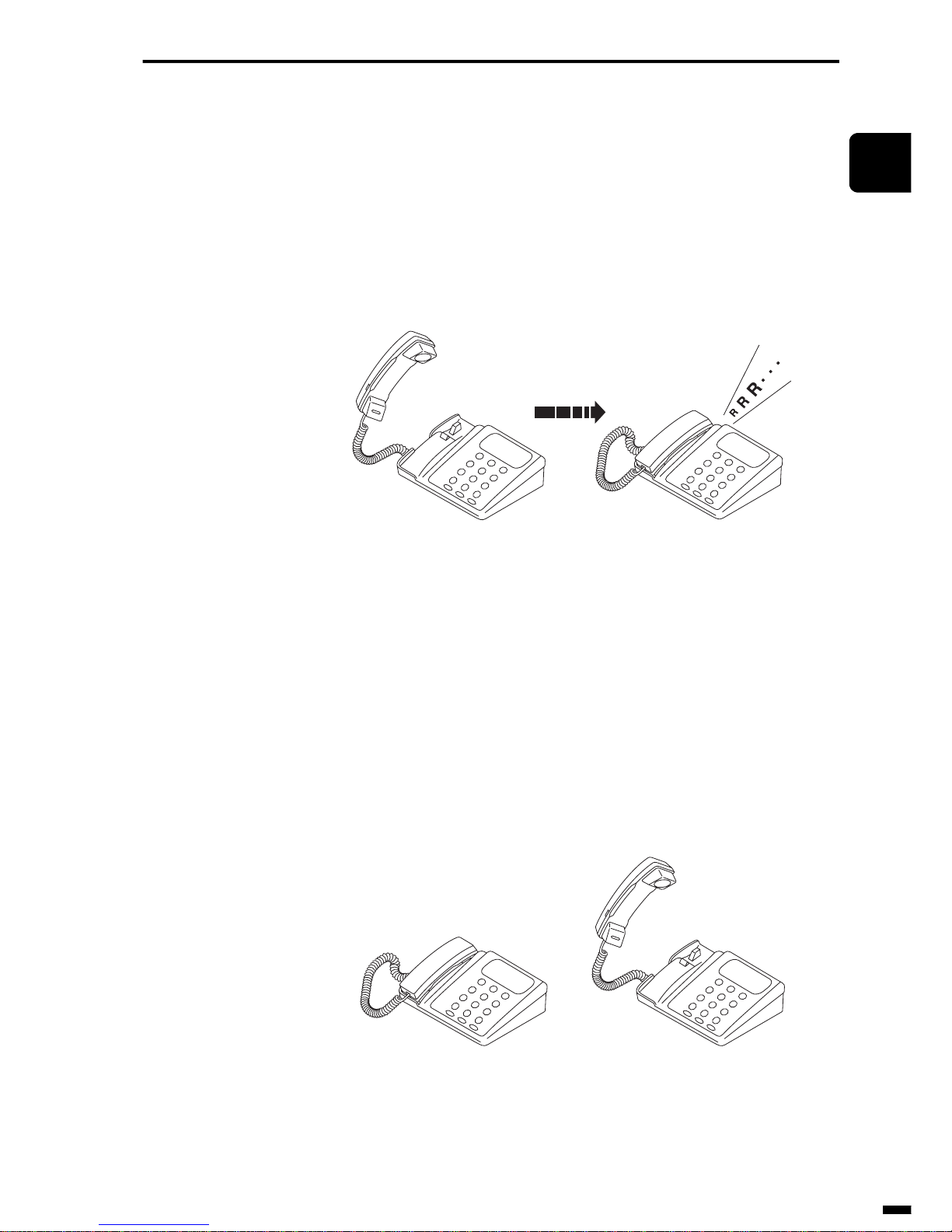
There are names for the party being called and the party making the call.
When we make a call, one of the two parties must first dial to call up the
other party by the bell on its telephone. Making a call in this way, that is,
dialing is called the “outgoing call”, and the call that arrives is called the
“incoming call”.
Fig. 1-3 Telephone Call State (1)
When you lift the handset, the handset is “off-hook”. When you hang up,
the handset is “on-hook”.
These days, some telephones have an on-hook button. F or e xample, even if
the handset is placed on the telephone body, pressing this on-hook button
sets the telephone to the same state (on-hook) as when the handset is
picked up.
Fig. 1-4 Telephone Call State (2)
Outgoing call Incoming call
Off-hookOn-hook
Page 12

BASIC OF TELEPHONE
1–4
1.3 How do you make a call?
When you call someone, you must take various actions.
Let’s consider each individual action needed for making a call.
(1) You pick up the handset. This means you are making a calling request.
The telephone exchange gets ready to connect you to your party.
(2) The exchange emits the dial tone to indicate it is ready for the called
number.
(3) You dial your party’s number. This is the dialing signal.
(4) When the telephone exchange receives your dialing signal, it attempts
to connect with your party. If your party is free, the exchange will
make the connection, and you will hear a ringing tone.
(5) When the other party picks up the handset, the exchange stops sending
the ringing tone, so that you can have a conversation.
(6) You have your conversation.
(7) You hang up.
When the called number is in use, the calling party hears a busy tone. Even
if the called party hangs up while the caller is listening, the calling party
will still hear the busy tone. So the calling party needs to dial again.
1.4 Voice Frequencies Carried by the Telephone
The human ear can hear sounds with frequencies between 10 Hz and
15,000 to 20,000 Hz. The human voice is composed of many different frequencies. To be able to transmit the full range of hearing over the phone
line would require very high-quality amplifiers and other equipment. Far
more than is practical.
The telephone transmits enough voice frequencies to understand what is
being said; usually between 300 to 3,400 Hz.
Page 13
1–5
1
2
3
4
5
6
ït
çi
BASIC OF TELEPHONE
2. STRUCTURE OF A TELEPHONE
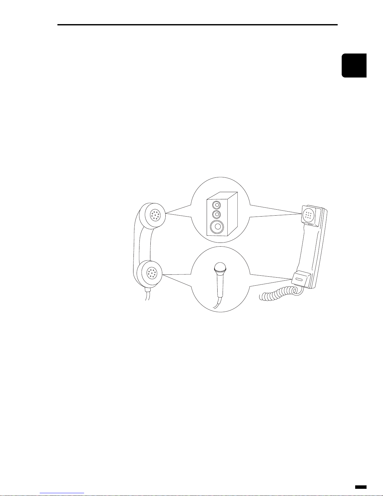
A telephone consists of a receiver (speaker), a transmitter (microphone), a
voice circuit, a dial, a bell (speaker), and a hook button.
Of these parts, the parts that play the most important roles are the transmitter and the receiver. The transmitter converts human voice to electrical signals, and the receiver converts the electrical signals from the other party to
voice.
Here, let’s learn about the mechanism of these parts and the roles that they
perform.
Fig. 1-5 Handset
Receiver
Transmitter
Page 14

BASIC OF TELEPHONE
1–6
2.1 Transmitter (Microphone)
The voice vibrates a diaphragm compressing/releasing carbon powder.
When carbon powder is compressed, its contact resistance decreases.
When the powder is released, its contact resistance increases. So direct
current varies corresponding to the change of pressure (voice). This is
called “voice current”. Recently, a microphone is applied to the transmitter
of the telephone.
Fig. 1-6 Transmitter and Voice Current
Carbon powder
Fixed electrode
Diaphragm
Air vibration
Contact
resistance
Voice current
Page 15
1–7
1
2
3
4
5
6
ït
çi
BASIC OF TELEPHONE
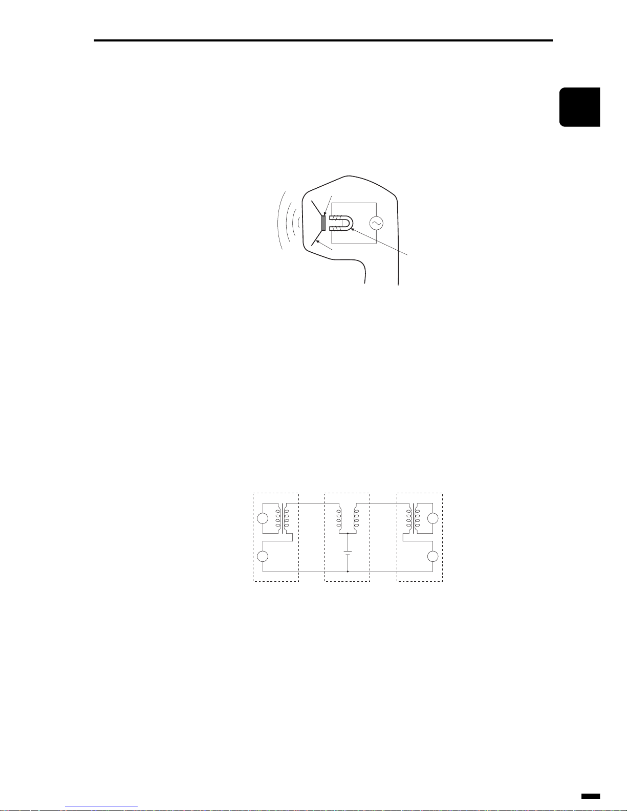
2.2 Receiver (Speaker)
The receiver acts just like an electromagnet. The receiver creates voice
waves by changing magnetic force, which move a vibrating diaphragm
according to the current strength.
Fig. 1-7 Receiver
2.3 Voice Circuit
When the transmitter and receiver are connected as shown in the Fig. 1-8
to make a voice circuit, voice can be transmitted in both directions along
the two wires.
Fig. 1-8 Two-way Circuit (Two Wires)
Armature
Permanent magnet
Diaphragm
R
R
T
T
Calling party Exchange Called party
T:Transmitter
R: Receiver
Page 16
BASIC OF TELEPHONE
1–8
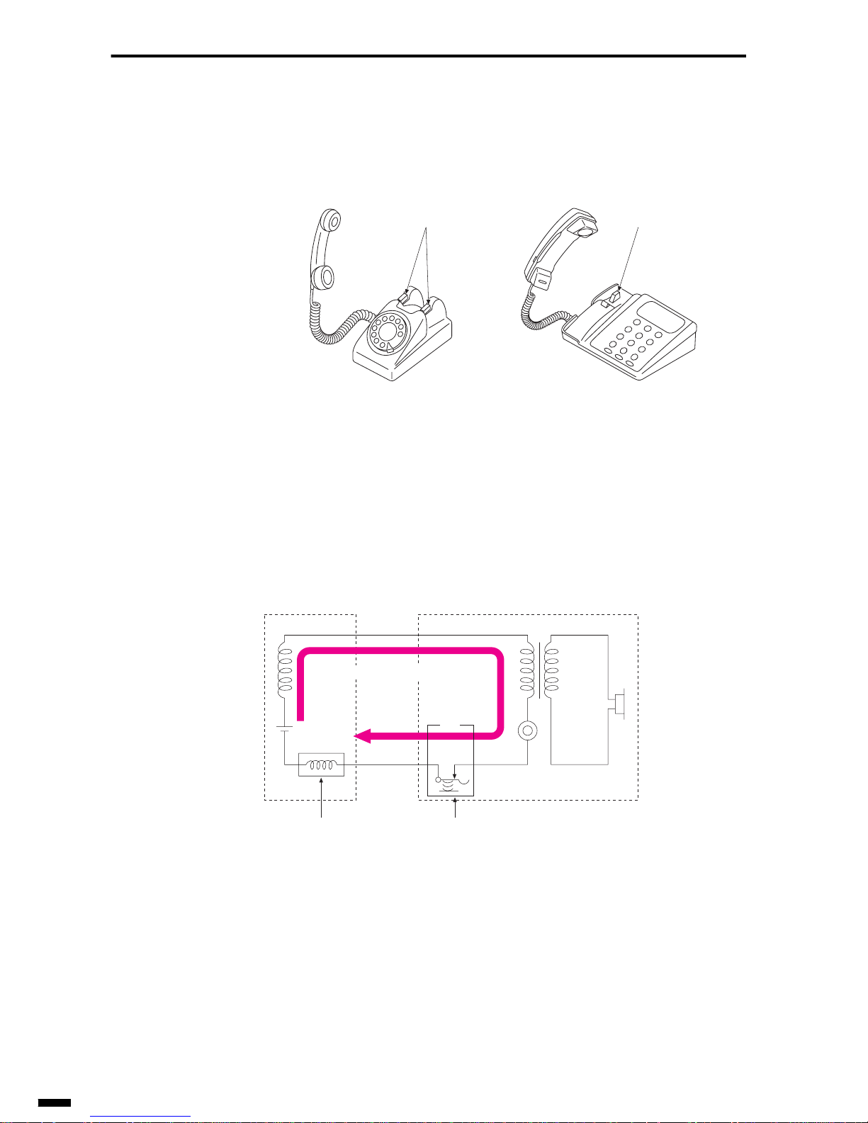
2.4 Hook Button
When a hook button is closed by picking up a handset, direct current flow s
to the telephone circuits.
Fig. 1-9 Hook Button
The purpose of this is twofold (i) so that direct current is made to flow to
the transmitter to provide current for sending voice when the handset is
picked up, and (ii) so that the exchange detects this direct current to recognize that the handset has been picked up.
Fig. 1-10 DC Loop
Picking up a handset is called “making a DC loop”. A DC loop lets the
exchange know that:
(1) The calling party (the party making the call) is ready to call someone.
(2) The called party answered. (The party receiving the call)
(3) The handset is on-hook.
Hook button Hook button
T: Transmitter
R: Receiver
HS: Hook switch
R
T
HS
Exchange Telephone
Direct
current
detector
Detects direct
current.
Closed when a handset is
picked up. (Off-hook state)
Direct current (DC) loop
Page 17

1–9
1
2
3
4
5
6
ït
çi
BASIC OF TELEPHONE
2.5 Dial
Dialling enables an exchange to connect one party to a requested number
according to a dialing signal. “DP” means the Dial pulse contact. The contact is usually closed. When you turn a dial and release it, the contact
opens the same number of times as the number you dialed. (When the
dialed number is 0, the contact opens 10 times.)
When a DC loop is made as shown in the Fig. 1-11 and the dial returns to
its start position after the number “4” is dialed, the DC loop is cut four
times. This is called the “dial pulse”.
Dialing using this dial pulse is called “pulse dial” due to the fact that numbers are dialed by this pulse.
Fig. 1-11 Dial Pulse
The exchange selects and calls up the other party by counting the number
of dial pulses.
Dials return to their start position at either of two speeds:
• 10PPS
• 20PPS
PPS (Pulse Per Second) indicates how many dial pulses are generated per
second.
T:Transmitter
R: Receiver
R
T
DP: Dial pulse contact
HS (Off-hook state)
HS: Hook switch
DP
ON
OFF
1
2
3
4
5
6
7
8
9
0
Dial return
DP
OFF
ON
Page 18

BASIC OF TELEPHONE
1–10
Here, we have described an example (number of dial pulses = N) where the
number of dial pulses is the same as the dialed number (N). However, in
some countries, the number of dial pulses is sometimes different as follows:
The number of dial pulses is the dialed number (N) + 1
The number of dial pulses is the dialed number (N) - 1
2.6 Bell (Speaker)
The calling identification (CI) signal from the exchange for notifying that
you have an incoming call is converted to the ring tone and is output.
Recently, a speaker or buzzer is used instead of the bell.
Dialed number 1 2 34567890
Number of dial pulses23456789101
Dialed number 1 2 34567890
Number of dial pulses10123456789
Page 19
1–11
1
2
3
4
5
6
ït
çi
BASIC OF TELEPHONE
3. TYPES OF TELEPHONES
There are three types of telephone: dial telephones and pushbutton telephones that are used on analog lines, and digital telephones that are used
on digital lines.
In this section, let’s learn about these types of telephones.
3.1 Dial Telephones
The type of telephone having a dial as explained earlier in section 2.5 is a
dial telephone.
3.2 Pushbutton Telephones
Pushbutton telephones differ from telephones that are operated by turning
a dial in that buttons are pushed to output dialing signals.
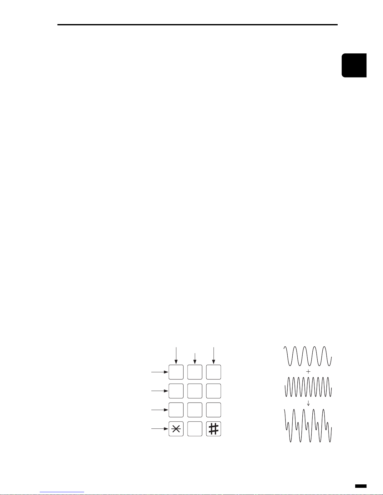
Pushbutton telephones have 12 buttons and have an oscillator inside to
generate seven different frequencies. For example, if you push button 1,
two frequency currents, 697 Hz and 1209 Hz, are sent simultaneously. This
is called DTMF (Dual Tone Multi Frequency), and dialing using this
DTMF is called “tone dial” due to the fact that numbers are dialed by this
tone. Dialing is also referred to as PB (Push Button) due to the fact that
buttons are pushed.
The exchange distinguishes numbers by this DTMF.
Of these 12 buttons, the * and # buttons are special buttons, and are used
for selecting various handy communications services.
Fig. 1-12 Pushbutton Telephone
12
4
7
0
98
65
3
697Hz
1209Hz
Mixed signals
(PB signal)
697Hz
770Hz
852Hz
941Hz
1209Hz 1477Hz
1336Hz
Page 20

BASIC OF TELEPHONE
1–12
Some pushbutton telephones have a dial selector switch for selecting
between tone dialing (PB) and pulse dialing. With these pushbutton telephones, if the selector switch is set to pulse dialing, the telephone outputs
dial pulses even though the telephone looks like a pushbutton telephone.
3.3 Digital Telephones
Though digital telephones also have 12 buttons just like a pushbutton telephone, the dialing signals are output not as a tone (frequency) but as a code
comprising a combination of digital 0s and 1s. Also, the signals for ringing
the bell on the other party’s telephone are sent as a code comprising a combination of digital 0s and 1s.
Page 21
1–13
1
2
3
4
5
6
ït
çi
BASIC OF TELEPHONE
4. CIRCUIT DIAGRAM IN THE TELEPHONE
In this section, let’s learn about the basic circuits inside a telephone.
4.1 Dial Telephones
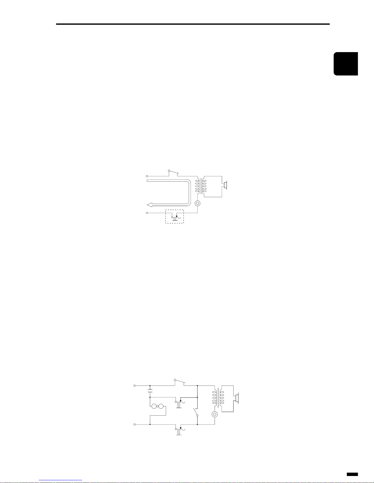
The Fig. 1-13 shows the basic circuit of a dial telephone.
Fig. 1-13 Basic Circuit of Dial Telephone
However, in actual fact, hook switch HS2 is provided in addition to switch
HS1 on dial telephones as shown in the Fig. 1-14. The bell circuit is closed
and short-circuited by the switch HS2 when the handset is picked up.
Ringing of the bell by dial pulses is thus prevented.
Dial telephones are also provided with a dial shunt contact DS to prevent
noise caused by the entry of dial pulses on the receiver. The DS closes
when you start dialing and opens when the dial has finished returning to its
start position.
Fig. 1-14 Circuit of Dial Telephone
T:Transmitter
R: Receiver
DP: Dial pulse contact
HS: Hook switch
R
T
HS
DP
T:Transmitter
R: Receiver
R
T
DP: Dial pulse contact
HS
1: Hook switch 1
DP
DS: Dial shunt contact
HS
2: Hook switch 2
HS1
HS2
DS
Bell
Page 22
BASIC OF TELEPHONE
1–14
4.2 Pushbutton Telephone
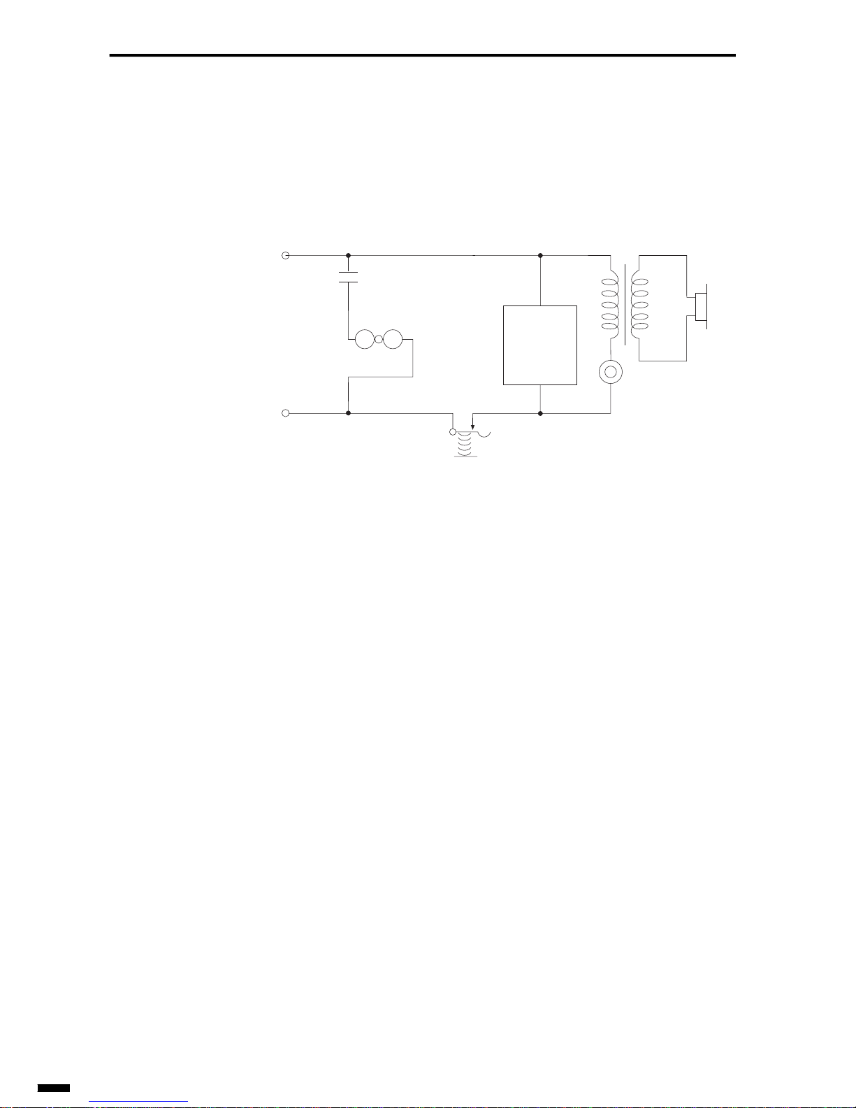
The Fig. 1-15 shows the basic circuit of a pushbutton telephone.
Basically, the only difference between the circuit of a pushbutton telephone and the circuit of a dial telephone is that the dialing signal generator
differs.
Fig. 1-15 Basic Circuit of Pushbutton Telephone
R
T
HS
Bell
T:Transmitter
R: Receiver
HS: Hook switch
12 pushbuttons
and DTMF
generation
circuit
Page 23
1–15
1
2
3
4
5
6
ït
çi
BASIC OF TELEPHONE
5. INTR ODUCTION TO THE TELEPHONE
NETWORK
We can talk to people over a long distance because we have an interlinked
telephone network which contains many telephone centers.
In this section, let’s learn about the mechanism of a telephone network.
5.1 Parts of a Telephone Network
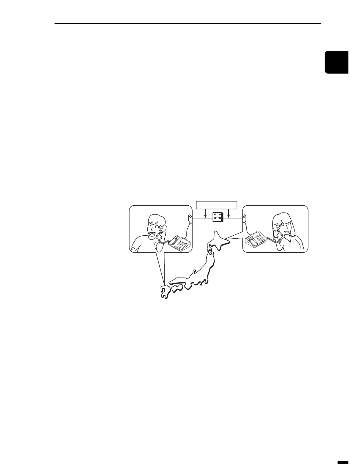
To communicate over a telephone line, you need two telephones, a telephone line, and an exchange system. The telephone is sometimes called a
terminal, because it is at each end of the telephone line.
Fig. 1-16 Parts of a Telephone Network
Telephone line
Exchange system
Telephone (Terminal) Telephone (Terminal)
Page 24
BASIC OF TELEPHONE
1–16
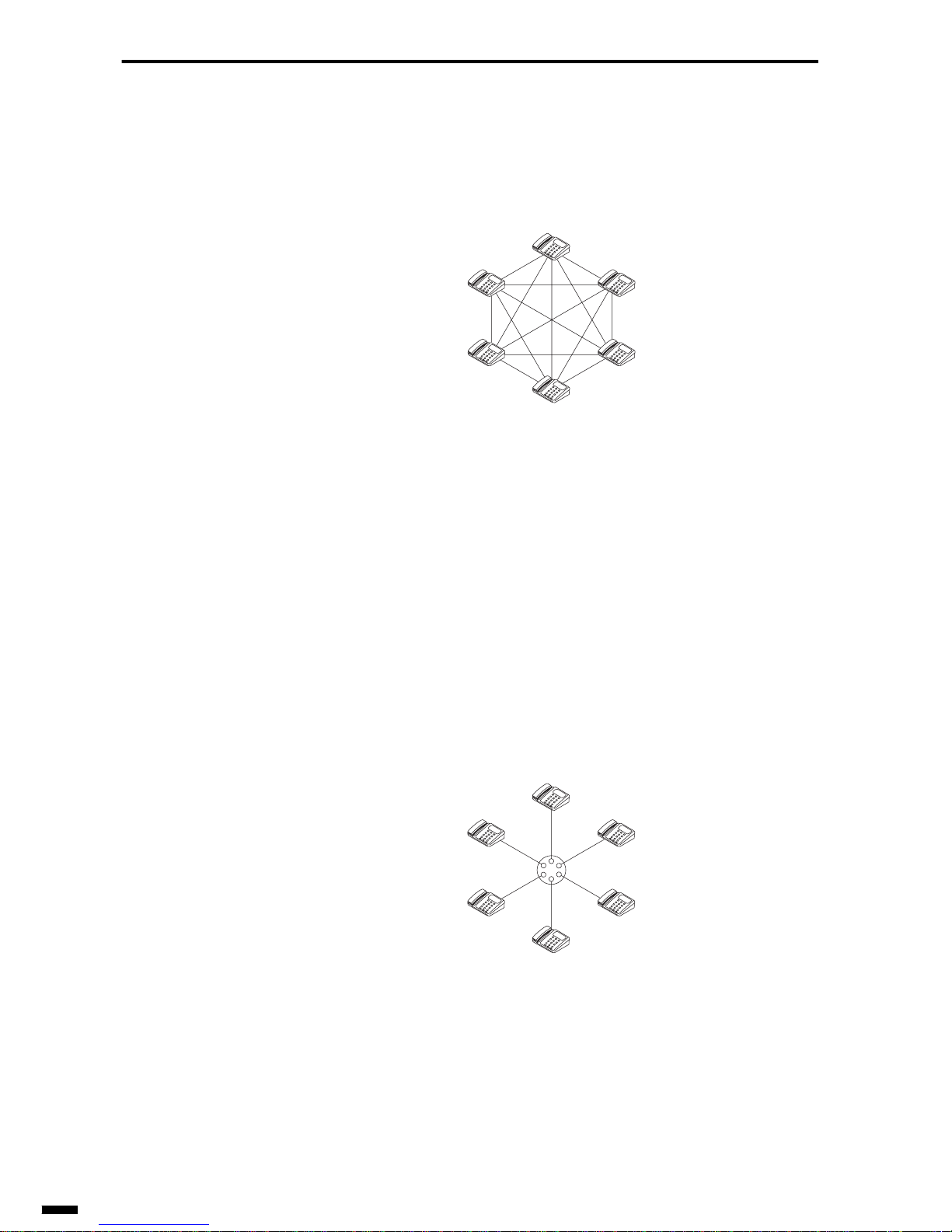
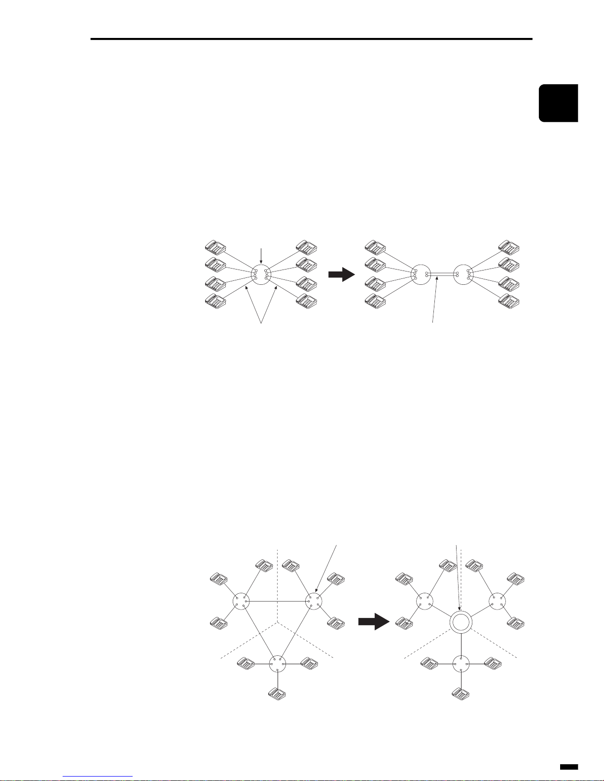
To simply connect two telephones without using an exchange, every telephone must be connected individually to every other telephone. This type
of network is called a mesh network.
Fig. 1-17 Mesh Network
In a mesh network, you need more telephone lines than telephones.
The number of lines needed to connect telephone is given by n(n-1)/2. (F or
example, you need about 500,000 lines for 1,000 telephones.)
Clearly, it is impossible to connect many telephones in a mesh network.
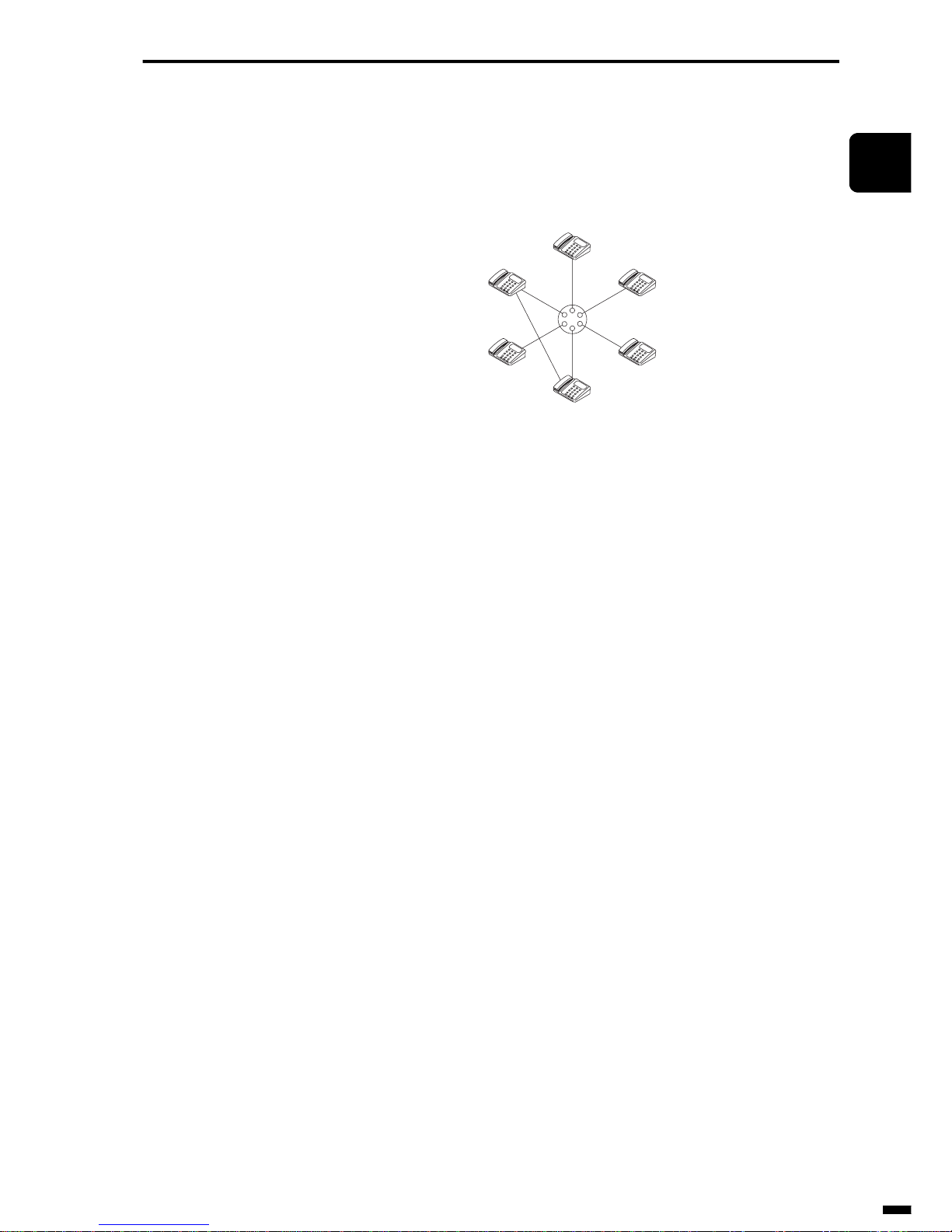
So, you can see that a telephone exchange is quite necessary. An exchange
connects a line to a telephone when it receives a calling request. In this
system, the number of lines can be equal to the number of telephones serviced by the exchange. This network system is called a star network.
Fig. 1-18 Star Network
Page 25
1–17
1
2
3
4
5
6
ït
çi
BASIC OF TELEPHONE
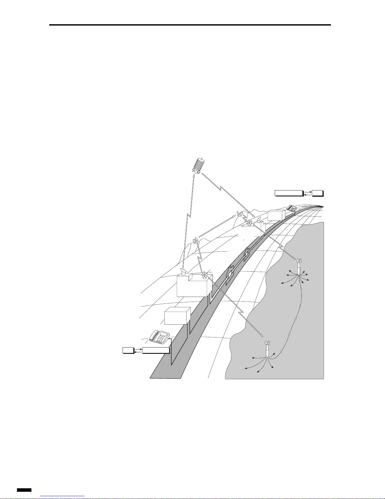
So far, we ha ve the mesh network and the star network. These are the basic
types of network systems. If we combine both networks into one system,
we have a hybrid network.
Fig. 1-19 Hybrid Network
Page 26
BASIC OF TELEPHONE
1–18
In this way, a telephone network consists of telephones used as a terminal
for converting voice to electrical signals and electrical signal back again to
voice, a telephone line for transmitting electrical signals to places far away,
and an exchange system for connecting two telephones.
Telephone lines come in various types: coaxial cable, optical fiber cable,
microwaves communications satellites and submarine cable.
The places where the exchange system is located is called the telephone
center (or the exchange center).
Fig. 1-20 Telephone Network Organization
Telephone
Transit
exchange
Subscriber
exchange
Telephone
Transit
exchange
Subscriber
exchange
Microwaveradio relay system
Satellite
communication
system
Optical fiber cable/
Coaxial cable system
Electrical signal
Voice
Electrical signal
Voice
Transit trunk
Subscriber line
Submarine
cable system
Page 27
1–19
1
2
3
4
5
6
ït
çi
BASIC OF TELEPHONE
5.2 Basic Structure of a Telephone Network System
As the number of telephones to be connected to the exchange increases
and the conversation area expands, it becomes more economic to set up
two or more exchanges and connect between exchanges by telephone lines
rather than terminating all of the telephone lines in a single exchange.
The line connecting two exchanges is called a transit trunk.
The line connecting an exchange and a telephone is called a subscriber
line.
Fig. 1-21 Subscriber Line and Transit Trunk
As the number of telephone centers increases, it becomes more economic
to set up an exchange for terminating only the transit trunks and connecting this exchange in the center in shape of a star rather than connecting
telephone centers to others in the shape of an interlinked network by
directly connected transit trunks.
This kind of exchange is called a transit exchange. An exchange that connects subscriber lines is called a subscriber exchange.
Fig. 1-22 Transit Exchange System
Exchange
Subscriber line
Transit trunk
Transit exchangeSubscriber exchange
Without a transit exchange (Mesh) With a transit exchange (Star)
Page 28
BASIC OF TELEPHONE
1–20
As the transit exchange relay-switches conversations between subscriber
exchange, we can consider transit exchange to be ranked (classified)
higher than the subscriber exchange. The rank for an exchange is called the
grade, and the telephone center is called the center grade. That is, the high
grade exchanges can route calls to a wider area.
Fig. 1-23 Center Grade
5.3 Nationwide Telephone Network (In case of Japan)
The nationwide network in Japan can be divided into subscriber areas
matched with administrative districts. A subscriber area has more than one
subscriber exchange to connect all the telephones in the area.
A call within the area is called a local call, and can be made by dialing an
exchange number and the subscriber number.
Fig. 1-24 Subscriber Area and Local Call
Transit exchange
Subscriber exchange
Telephone
Exchange
Local call
Subscriber area
Page 29
1–21
1
2
3
4
5
6
ït
çi
BASIC OF TELEPHONE
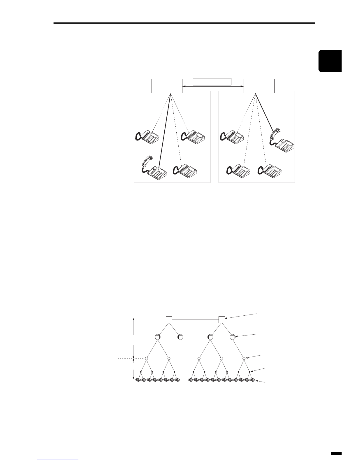
A call made between subscriber areas is called a long-distance call, and
can be made by dialing an area code, an exchange number, and a subscriber number.
Fig. 1-25 Subscriber Area and Long-Distance Call
The network for local calls is the local network. And the line and the
exchange for these calls are called the local line and the local exchange.
The network for long-distance calls is toll network. And the line and the
exchange for the long-distance call are called the toll line and the toll
exchange.
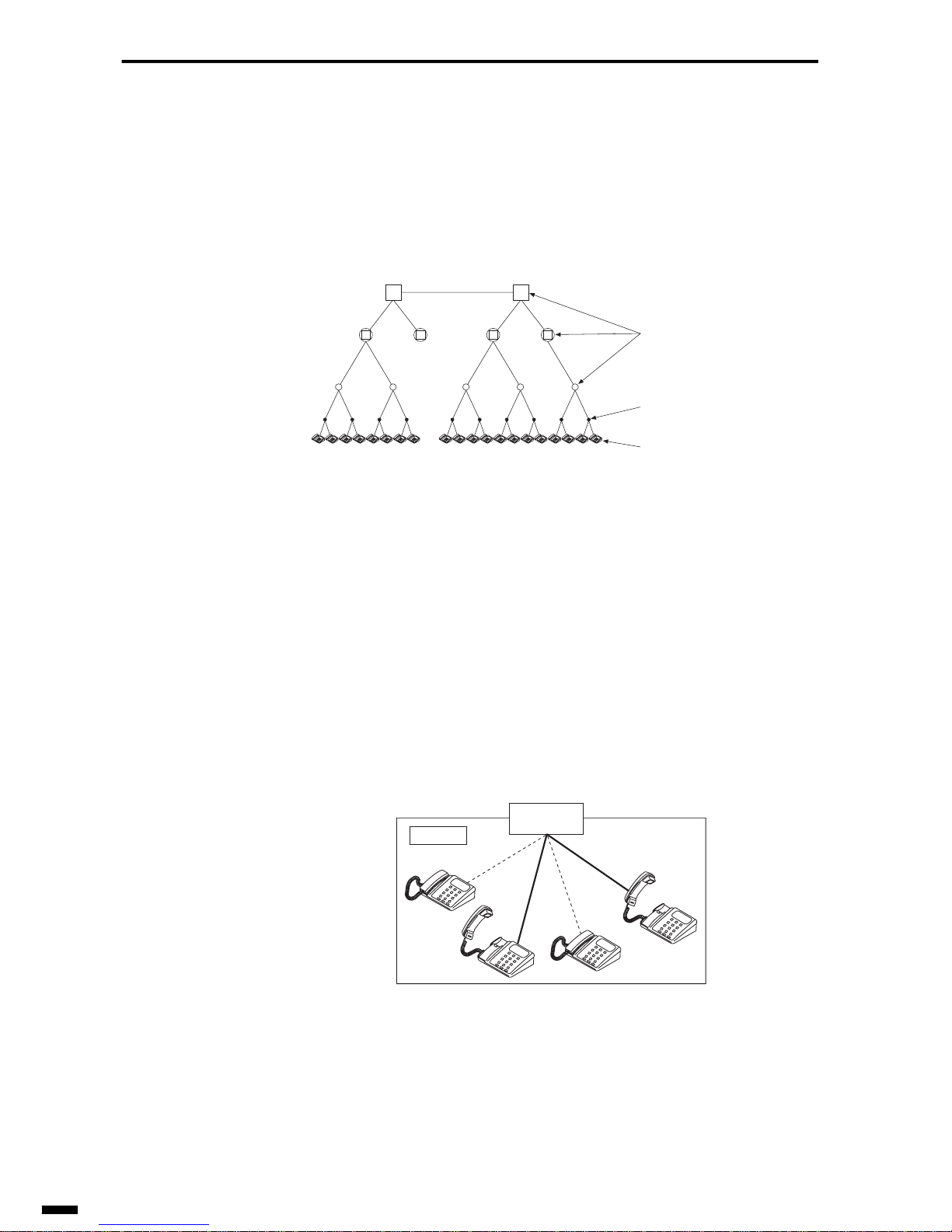
A toll exchange is classified into three ranks: toll centers, district centers,
and regional centers.
Fig. 1-26 Structure of Telephone Network
• Regional center (RC)
RCs have been established in Sapporo, Sendai, Tokyo, Nagoya, Kanazawa,
Osaka, Hiroshima, and Fukuoka.
Subscriber
exchange
Subscriber area A Subscriber area B
Long-distance call
Subscriber
exchange
End office (EO)
Subscriber
Toll line
Local line
Toll center (TC)
District center (DC)
Regional center (RC)
Page 30
BASIC OF TELEPHONE
1–22
• District center (DC)
DCs have been established in every seat of prefectural government of the
same rank city.
• Toll center (TC)
TCs have been established at central towns in a district center area.
• End office (EO)
An end office (EO) is an office that connects telephones in a subscriber
area.
5.3.1 Local telephone network
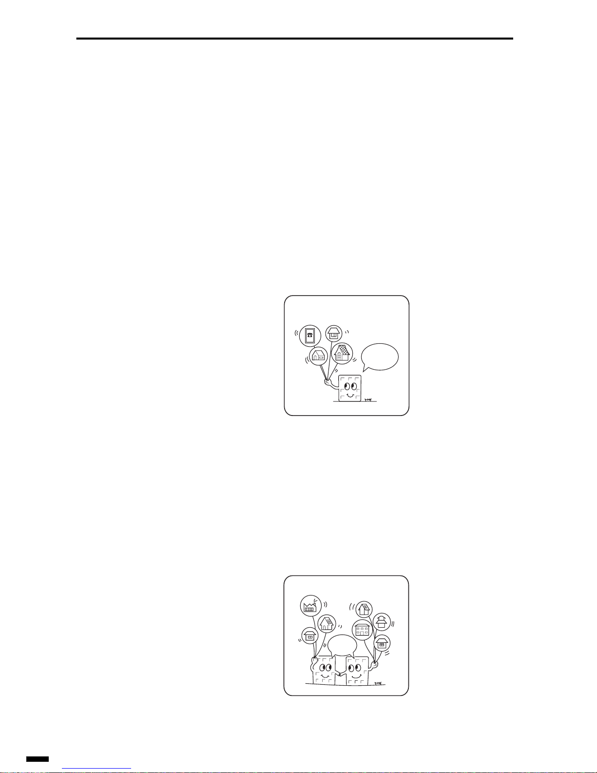
The subscriber area has one end office, which connects all the telephones
in the area. In this case, the subscriber area is called a single office area.
Fig. 1-27 Single Office Area
As the number of telephones increase, there will also be an increase in the
number of end offices called branches. These branch offices are connected
in a mesh network. In this case, the subscriber area is called a multiple
office area.
Fig. 1-28 Multiple Office Area
Subscriber area (Single office area)
I'm a single
office.
Subscriber area (Multiple office area)
We are
multiple
offices.
Page 31
1–23
1
2
3
4
5
6
ït
çi
BASIC OF TELEPHONE
The big cities have a transit exchange (a local tandem e xchange office) in a
star network. Generally, a hybrid network is formed when many calls concentrate on certain lines.
Fig. 1-29 Hybrid Network
Subscriber area
We are
multiple
offices.
Transit
exchange
Page 32
BASIC OF TELEPHONE
1–24
5.3.2 Toll network
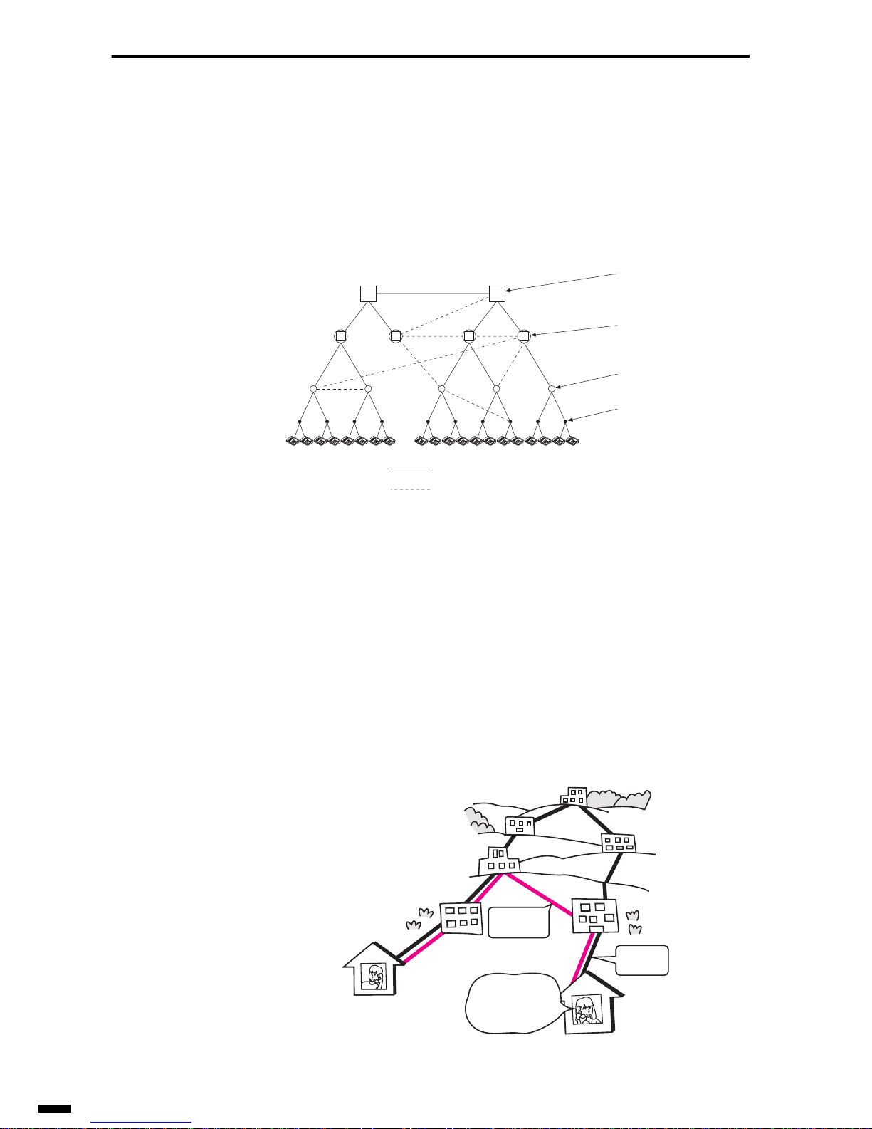
The toll network is formed by three classes of star networks connected
with upper centers and lower centers. The topmost centers form a mesh
network. The nationwide toll network hierarchy of toll networks is called
the toll band system.
Fig. 1-30 Toll Network
There are two kinds of transit trunk. One is the normal transit trunk, which
connects upper and lower centers in the nationwide hierarchy. The other is
the traversal trunk, which ignores this hierarchy and connects two centers
to handle a great deal of calls. For this reason, there are actually many connection routes, and the quality of a conversation is affected by which route
is taken to connect a call.
Fig. 1-31 Actual Connection Route
End office
Toll center
District center
Regional center
Transit trunk
Traversal trunk
Yesterday's
route
Today's
route
I could hear
you better
yesterday.
Page 33
1–25
1
2
3
4
5
6
ït
çi
BASIC OF TELEPHONE
6. TELEPHONE EXCHANGES
The exchange system and the telephone network have made simultaneous
progress. At first, people used the manual exchange, but now the automatic
exchange has replaced the manual exchange in most offices. In this section, let’s learn about the types of telephone exchange and how they work.
6.1 Types of Exchanges
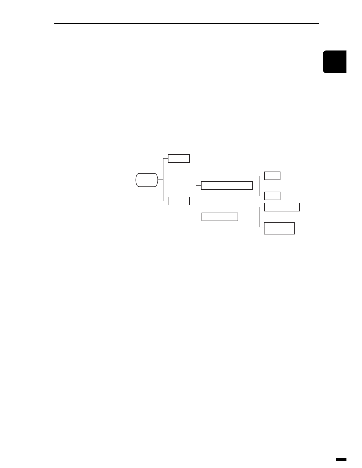
The Fig. 1-32 shows the various types of exchange system.
Fig. 1-32 Types of Exchanges
Hardly any manual exchanges are in active use today. So, the following
describes digital exchanges.
(1) Step-by-step (S X S) (A type/H type)
• This mechanically proceeds with operation by dial pulses for each
dialed digit.
• This has many switch contacts and provides a mechanical exchange.
So normal transmission may be disturbed by a lot of noise. This is not
suitable for facsimile use.
• As only dial speed 10PPS telephones can be connected, this is already
an outmoded type of exchange.
(2) Crossbar type (C type)
• This makes connection only after all digits have been entered.
• This is reliable because it scarcely wears out.
• This has a small amount of switch contacts and provides high quality
for calls.
• This is applicable both dial telephones and pushbutton telephones.
And this type enables many other services to be used.
Exchange
system
Manual
Automatic
Step-by-step
Common control
A type
H type
Crossbar type
Electronic
exchange
Page 34
BASIC OF TELEPHONE
1–26
(3) Electronic exchange (D type)
• This has the same function as crossbar’s. Moreover, the electronic
exchange uses a computer as its control unit and provides high reliability.
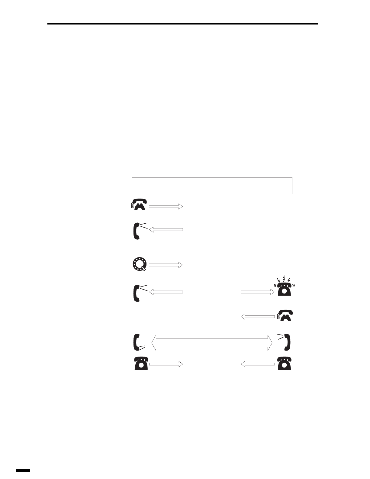
6.2 The Exchange
An exchange is a device, so it cannot talk or listen like a human being. For
this reason, the telephone sends signals that the exchange can understand,
and the exchange sends signs to the telephone that a human being can
understand.
The Fig. 1-33 shows how an exchange works.
Fig. 1-33 How an Exchange Works
Operation on
calling telephone
Operation on
exchange
Operation on
called telephone
The exchange gets
ready.
The exchange is
ready to receive
a number.
After receiving the
signal, the exchange
finds the called
number.
The exchange
connects the line.
(Unless the called
number is busy.)
Conversation
The exchange stops
ring tone, ring-back
tone and connects
the line.
The exchange
disconnects and
halts the DC loop.
DC loop
Dial tone
The handset is off hook.
You hear a dial tone.
Dialing pulse
You dial.
Ring-back tone
You hear ring-back tone.
The handset is on hook.
Ring tone
Telephone rings.
The handset is on hook.
DC loop
The handset is off hook.
Page 35

1–27
1
2
3
4
5
6
ït
çi
BASIC OF TELEPHONE
6.2.1 Details of signals and signs sent from the telephone
to the exchange
(1) DC loop
This is for notifying the exchange that a person has picked up the handset.
A DC loop has the following meaning:
• Calling request and response (when DC loop is made)
• End of conversation (when DC loop is cut)
(2) Dialing signal
This signal is used to find the called party’s telephone. The signal is generated by dialing.
6.2.2 Details of signals and signs sent from the exchange
to the telephone
(1) Dial Tone
This tone indicates that the exchange is ready and you may send the dialing signals.
(2) Ring Back Tone
This tone indicates to the caller that the other party is being called up.
(3) Busy Tone
This tone indicates to the caller that the other party is busy.
(4) Calling Identification (CI)
This signal notifies the called party that there was a call from a caller.
This signal rings the bell on the called party’s telephone.
(5) Re-order Tone
This tone notifies the caller that the called party put down the handset during a conversation and that the conversation was cut.
Some exchange do not output the Re-order Tone.
Of these signals that are sent to the telephone from the exchange, the signals (other than the CI) that the caller can hear through the handset are
called audio tones.
Page 36

1–28
Notes
Page 37

CHAPTER
2
1
2
3
4
5
6
ït
çi
2 GENERAL DESCRIPTION
OF A FACSIMILE
1. WHAT IS A “FACSIMILE?” ....................................................... 2-2
1.1 Established Rules of Communication.............................. 2-2
1.2 Control Procedure........................................................... 2-2
1.3 Facsimile Groups ............................................................ 2-3
1.4 Telephone Lines..............................................................2-3
1.5 Types of ITU-T Recommendations.................................. 2-4
1.6 How Images are Transmitted........................................... 2-8
2. STRUCTURE OF A FACSIMILE............................................2-13
2.1 Reading Section............................................................ 2-15
2.2 Recording Section......................................................... 2-18
2.3 MODEM ........................................................................ 2-21
2.4 NCU board (Network Control Unit board) ..................... 2-22
2.5 System Control Section................................................. 2-22
3. THE FUTURE OF FACSIMILES ............................................ 2-23
3.1 Color Facsimiles............................................................ 2-23
3.2 LAN-networked Facsimiles............................................ 2-23
3.3 Internet Facsimiles........................................................ 2-24
Page 38

GENERAL DESCRIPTION OF A FACSIMILE
2–2
1. WHAT IS A “FACSIMILE?”
A facsimile is a machine that is connected to the telephone line instead of
the telephone, and transmits and receives documents instead of holding
conversations.
In this section, let’s start with a description of the rules governing facsimiles.
1.1 Established Rules of Communication
The communications equipment used for communications via public telegraph and telephone facilities must be designed to conform to the recommendations specified by the ITU-T. Communications must also conform to
ITU-T recommendations.
Facsimiles are designed to conform to these recommendations as they use
telephone lines to perform communications.
At this point, let’s consider why established rules of communication (ITUT recommendations) are necessary. Communications must be possible
between facsimiles made by different manufacturers. If facsimiles were
designed to conform to individual manufacturers’ standards, we would not
be able to transmit or receive documents between facsimiles made by different manufacturers. It is, naturally, very advantageous for today’s modern information society that facsimile communications be possible via
telephone lines anywhere there is a telephone using any type of facsimile.
This is why established rules of communication (ITU-T recommendations)
are required for facsimile communications.
1.2 Control Procedure
The purpose of a facsimile is to transmit a image of a document to another
facsimile. Actually, the two facsimiles transmit and receive control procedure signals before and after image signals are transmitted, to notify each
other of the communication. Here, let’s bring to mind an instance of someone making a telephone call. Before you state your business, you say
“Hello?” or tell other person your name. Facsimiles also perform this same
type of transaction using fixed control procedures.
All of these control procedures are specified according to ITU-T recommendations.
Page 39

2–3
1
2
3
4
5
6
ït
çi
GENERAL DESCRIPTION OF A FACSIMILE
1.3 Facsimile Groups
ITU-T recommendations classify facsimiles into groups called “G3” and
“G4.” G3 facsimiles enable the transmission of ISO A4-size type documents in about one minute on a public telephone network. G4 facsimiles,
as a general rule, enable the error-free reception of documents on a public
digital line. Both G3 and G4 facsimiles handle image data as digital signals. Previously, there also existed the G1 and G2 facsimile groups that
handled picture data as analog signals. However, these two groups have
currently been deleted from the ITU-T recommendations.
These days, mention the word “facsimile” and you are generally referring
to a G3 facsimile whose use has spread to households. G4 facsimiles are
capable of transmitting pictures faster and at higher quality than a G3 facsimile. Though they are still expensive, their popularity is expected to gain
in the future.
1.4 Telephone Lines
A facsimile is a machine that uses telephone lines to transmit images. So,
we must understand telephone lines in order to understand facsimiles.
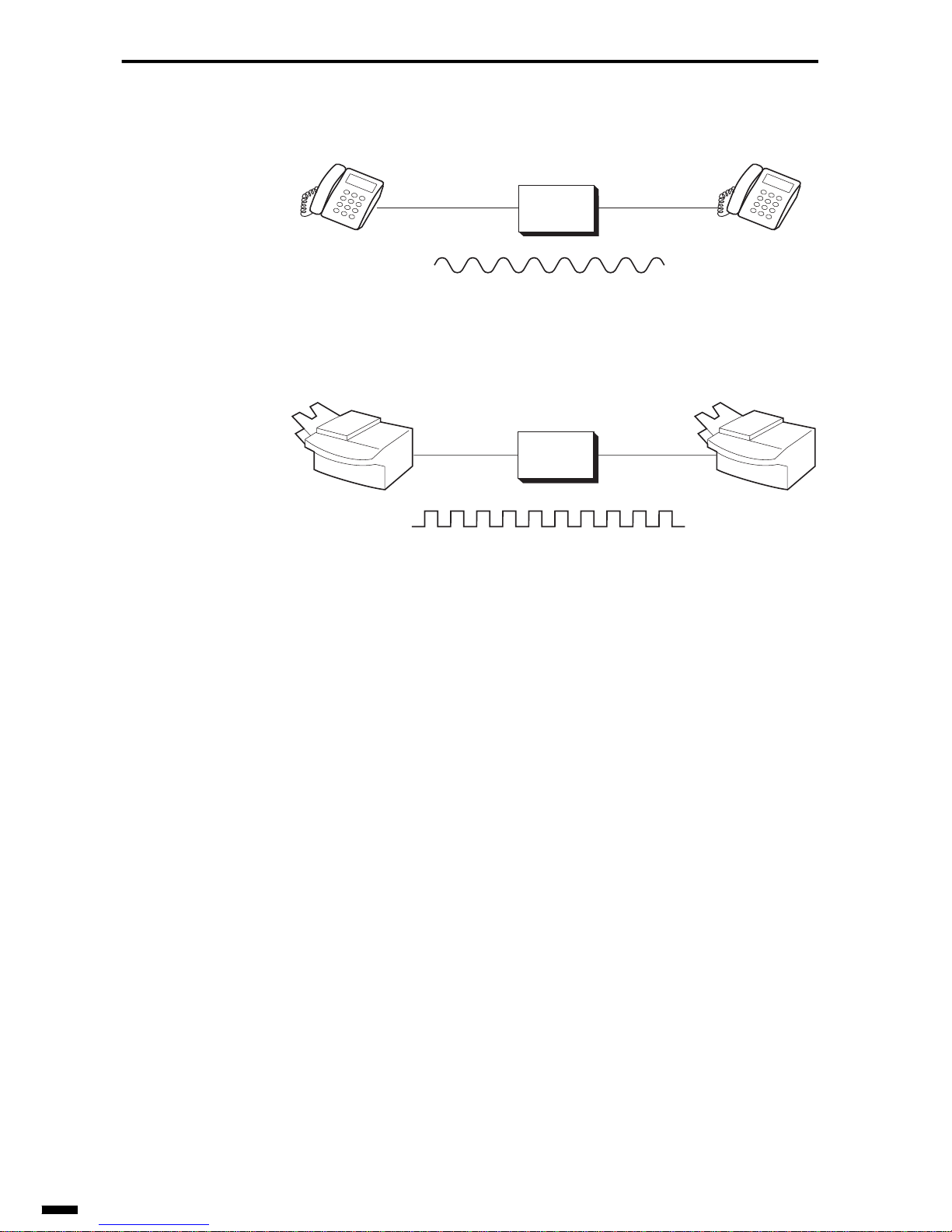
There are various kinds of telephone lines: analog lines, digital lines and
Facsimile communication network services.
The telephone line that we use most of the time is an analog line called a
PSTN (Public Switched Telephone Network) which has been designed for
transmitting speech. The information that a PSTN is capable of transmitting are analog signals that are obtained by converting changes in current
or voltage as they are to waveforms. When image data is transmitted on a
G3 facsimile, it is converted to analog signals before it is transmitted.
Analog lines have spread throughout the world to the point that any simple
mention of telephone lines generally refers to analog lines.
ISDN (Integrated Services Digital Network) is a digital line capable of
sending all various media such as speech, documents, video and data as 0
and 1 digital signals. G4 facsimiles are capable of transmitting imae data
as it is. When speech is transmitted, the analog signals are converted once
to 0 and 1 digital signals before they are transmitted.
As digital lines are capable of transmitting digital signals as they are, transmission speeds are high and there are no transmission errors. For this reason, digital lines are ideal for personal computer-based communications
and the Internet, and are expected to expand further in the future.
Page 40
GENERAL DESCRIPTION OF A FACSIMILE
2–4
Fig. 2-1 Analog Line and Digital Line
In Japan, there are lines exclusively for facsimile communications called
Facsimile communication network services. As a facsimile does not hold
conversations simultaneously like a telephone, the facsimile adopts a
method of storing the documents to be transmitted on the network, and
then transmitting them at once using a high-speed line. By this method, the
line is separated from the facsimile after the document is stored, to ensure
efficient use of the line. For this reason, you are charged by the number of
document sheets that you transmit regardless of the transmission time.
1.5 Types of ITU-T Recommendations
This section describes the main details of recommendations relating to G3
and G4 facsimile.
1.5.1 G3 facsimile-related recommendations
• T.0 (Classification of facsimile terminals for document transmission
over the public networks)
• Terminals for use over the public telephone network (Group 3 terminals)
Exchange
Exchange
Analog Line
Digital Line
G4 facsimile,
digital telephone,
etc.
G4 facsimile,
digital telephone,
etc.
Telephone,
G3 facsimile, etc.
Telephone,
G3 facsimile, etc.
Page 41

2–5
1
2
3
4
5
6
ït
çi
GENERAL DESCRIPTION OF A FACSIMILE
• T.4 (Standardization of Group 3 facsimile terminals for document
transmission)
• Scanning track
• Dimensions of terminals
• Transmission time per total coded scan line
• Coding scheme
• T.6 (Facsimile coding schemes and coding control functions for
group 4 facsimile apparatus)
• Facsimile coding schemes and coding control functions for black and
white images (MMR coding)
• T .30 (Procedures f or document f acsimile tr ansmission in the general
switched telephone network)
• Description of a facsimile calls
• Tonal signal functions and formats
• Binary coded signalling procedure
• T.85 (Application profile for Recommendation T. 82-Progressive bilevel image compression (JBIG coding scheme) for facsimile apparatus)
• Application profile of single-progression sequential coding machine
• V.8 (Procedures for starting sessions of data transmission over the
public switched telephone network)
• Description of signals to be switched between DCE (Data Communications Equipment) when establishment of a data transmission session
is required over the public switched telephone network
• V.17 (A 2-wire modem for facsimile applications with rates up to
14400 bit/s)
• TC7200 bps, TC9600 bps, 12000 bps and 14400 bps modulation
schemes in group 3 image transmission
• V .21 (300 bits per second duple x modem standardiz ed f or use in the
general switched telephone network)
• Conditions of transmission equipment relating to the transmission of
group 3 procedure signals (300 bps)
• V.27ter (4800/2400 bits per second modem standardized for use in
the general switched telephone network)
• 2400 bps and 4800 bps modulation schemes in group 3 image transmission
• V .29 (9600 bits per second modem standardiz ed f or use on point-topoint 4-wire leased telephone-type circuits)
• 7200 bps and 9600 bps modulation schemes in group 3 image transmission
Page 42

GENERAL DESCRIPTION OF A FACSIMILE
2–6
• V.34 (A modem operating at data signalling rates of up to 33600 bit/
s for use on the general switched telephone network and on leased
point-to-point 2-wire telephone-type circuits)
• Conditions of transmission equipment relating to the transmission of
group 3 proceudre signals (600 bps, 1200 bps, 2400 bps)
• 2400 bps, 4800 bps, 7200 bps, 9600 bps, 12000 bps, 14400 bps, 16800
bps, 19200 bps, 21600 bps, 24000 bps, 26400 bps, 28800 bps, 31200
bps and 33600 bps modulation schemes in group 3 transmission
1.5.2 G4 facsimile-related recommendations
• T.0 (Classification of facsimile terminals for document transmission
over the public networks)
• Terminals for use over the public data networks (Group 4 terminals)
• T.6 (Facsimile coding schemes and coding control functions for
group 4 facsimile apparatus)
• Facsimile coding schemes and coding control functions for black and
white images (MMR coding)
• T.90 (Characteristics and protocols for terminals for telematic services in ISDN)
• ISDN B-channel circuit-switched mode
• ISDN B-channel packet-switched mode
• T.411 (Information technology-Open Document Architecture (ODA)
and interchange format: Introduction and general principles
• T.412 (Information technology-Open Document Architecture (ODA)
and interchange format: Document structures)
• T.414 (Information technology-Open Document Architecture (ODA)
and interchange format: Document profile)
• T.415 (Information technology-Open Document Architecture (ODA)
and interchange format: Open Document Interchange Format
(ODIF))
• T.416 (Information technology-Open Document Architecture (ODA)
and interchange format: Character content architectures)
• T.417 (Information technology-Open Document Architecture (ODA)
and interchange format: Raster graphics content architectures)
• T.418 (Information technology-Open Document Architecture (ODA)
and interchange format: Geometric graphics content architecture)
• T.431 (Document Transfer And Manipulation (DTAM) -Ser vices and
protocols-Introduction and general principles)
• T.432 (Document Transfer And Manipulation (DTAM) -Ser vices and
protocols-Service definition)
Page 43

2–7
1
2
3
4
5
6
ït
çi
GENERAL DESCRIPTION OF A FACSIMILE
• T.433 (Document Transfer And Manipulation (DTAM) -Services and
protocols-Protocol specification)
• T .503 (A document application profile for the interchange of Group 4
facsimile documents)
• Clarification of formats to be applied to group 4 facsimile document
interchange
• T.521 (Communication application profile BT0 for document bulk
transfer based on the session service)
• T.563 (Terminal characteristics for Group 4 facsimile apparatus)
• Stipulation of general characteristics of group 4 facsimile terminals
Page 44
GENERAL DESCRIPTION OF A FACSIMILE
2–8
1.6 How Images are Transmitted
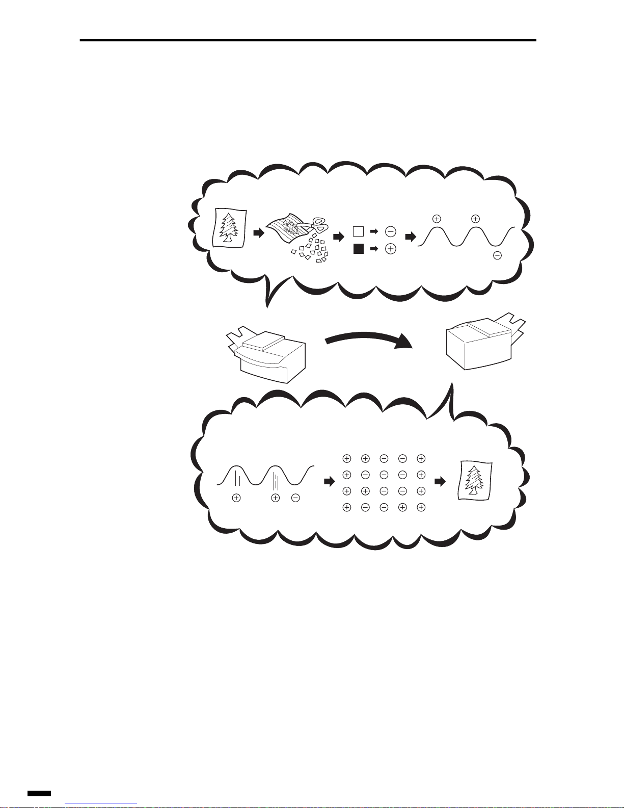
The sender facsimile transmits the image over the telephone line, and the
receiver facsimile receives and prints out the transmitted image.
The figures below illustrate how images are sent.
Fig. 2-2 How Images Are Transmitted
1. Image
2.Division into
pixels
3. Conversion into
electrical signals
4.Modulation
6. Demodulation
7.Reassembly of pixels
8.Reproduction
of image
Transmission
Reception
5.Transmission
/reception
White
pixel
Black
pixel
Minus
signal
Plus
signal
Page 45
2–9
1
2
3
4
5
6
ït
çi
GENERAL DESCRIPTION OF A FACSIMILE
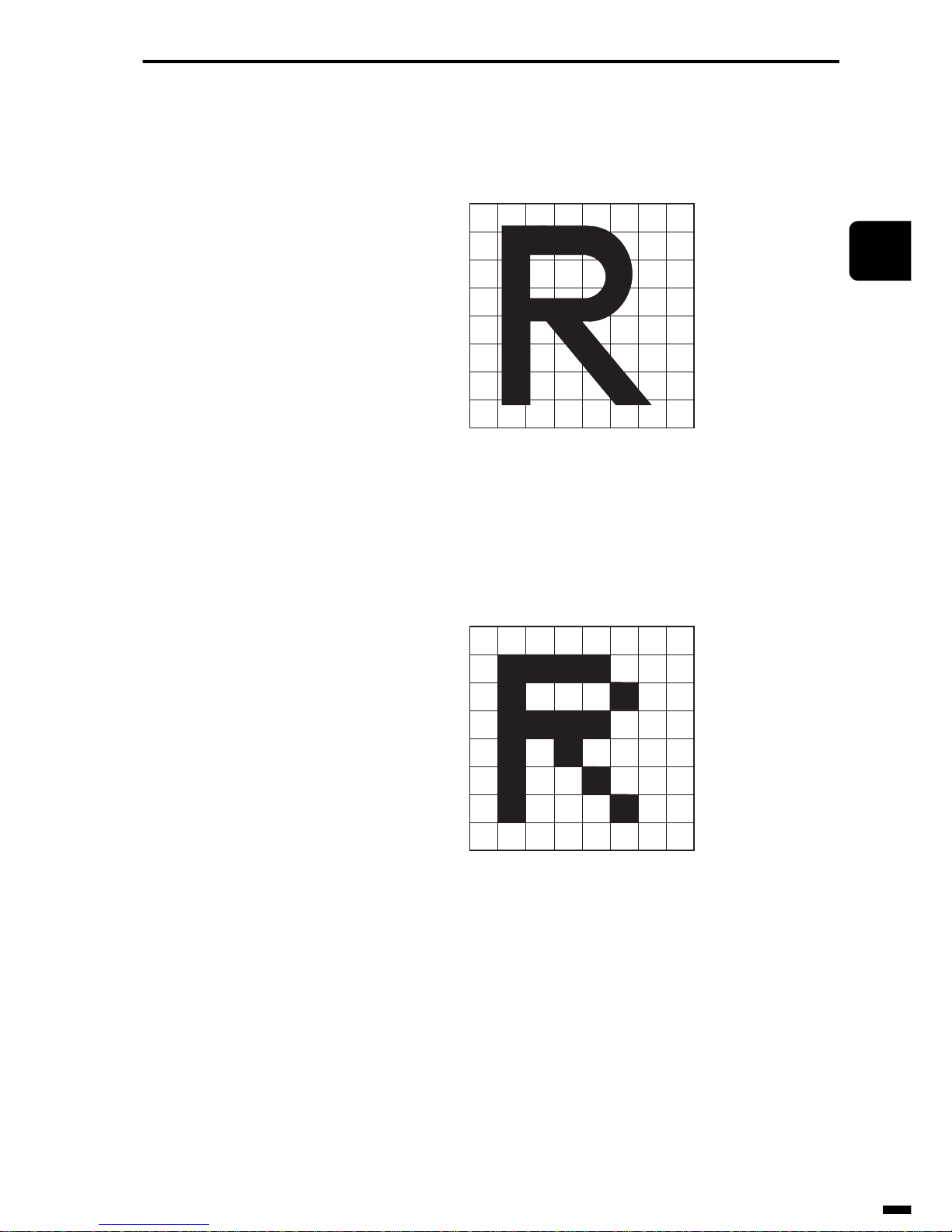
(1) Image
This is the original image before it is transmit.
Fig. 2-3 Image
(2) Division into pixels
The image is divided into either white or black pixels.
Fig. 2-4 Division of Image into pixels
a
b
c
d
e
f
g
h
12345678
a
b
c
d
e
f
g
h
12345678
Page 46
GENERAL DESCRIPTION OF A FACSIMILE
2–10
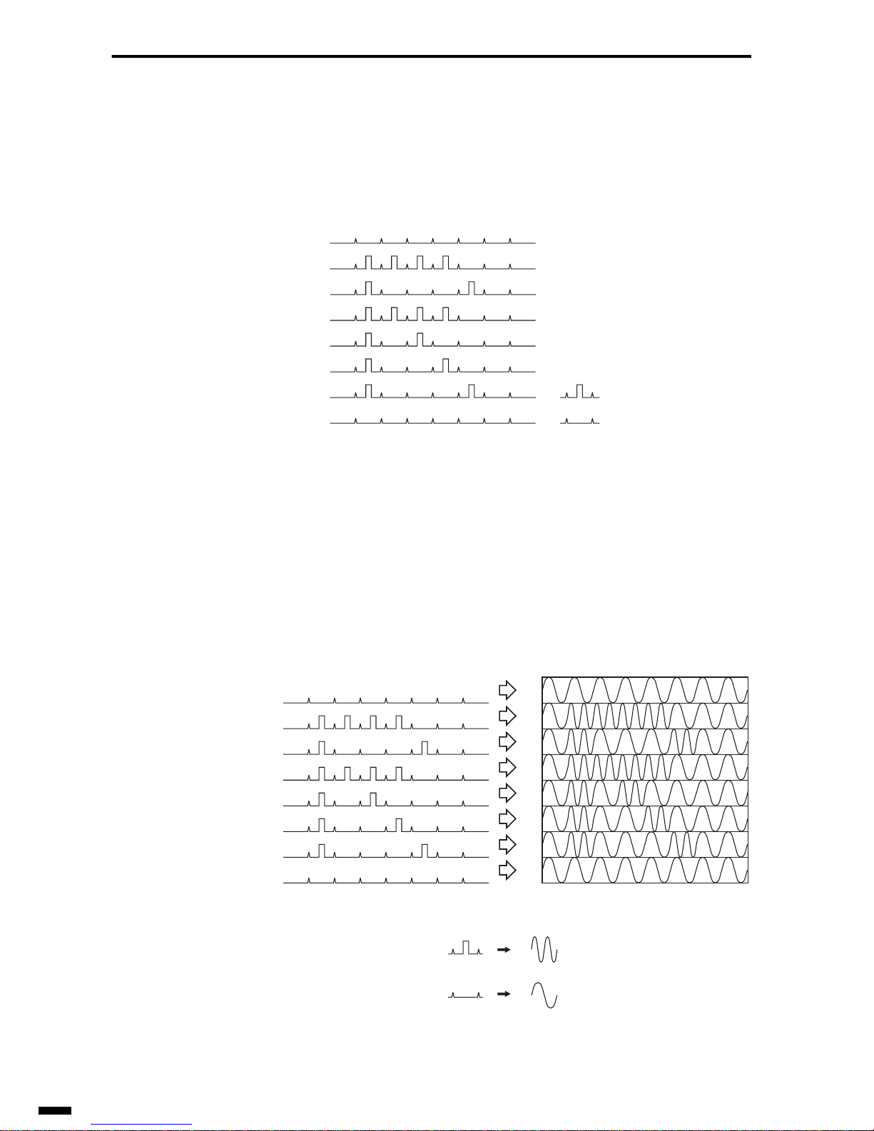
(3) Conversion into electrical signals
Black pixels are converted into High level signals, and white pixels are
converted into Low level signals.
Fig. 2-5 Conversion into Electrical Signals
(4) Modulation
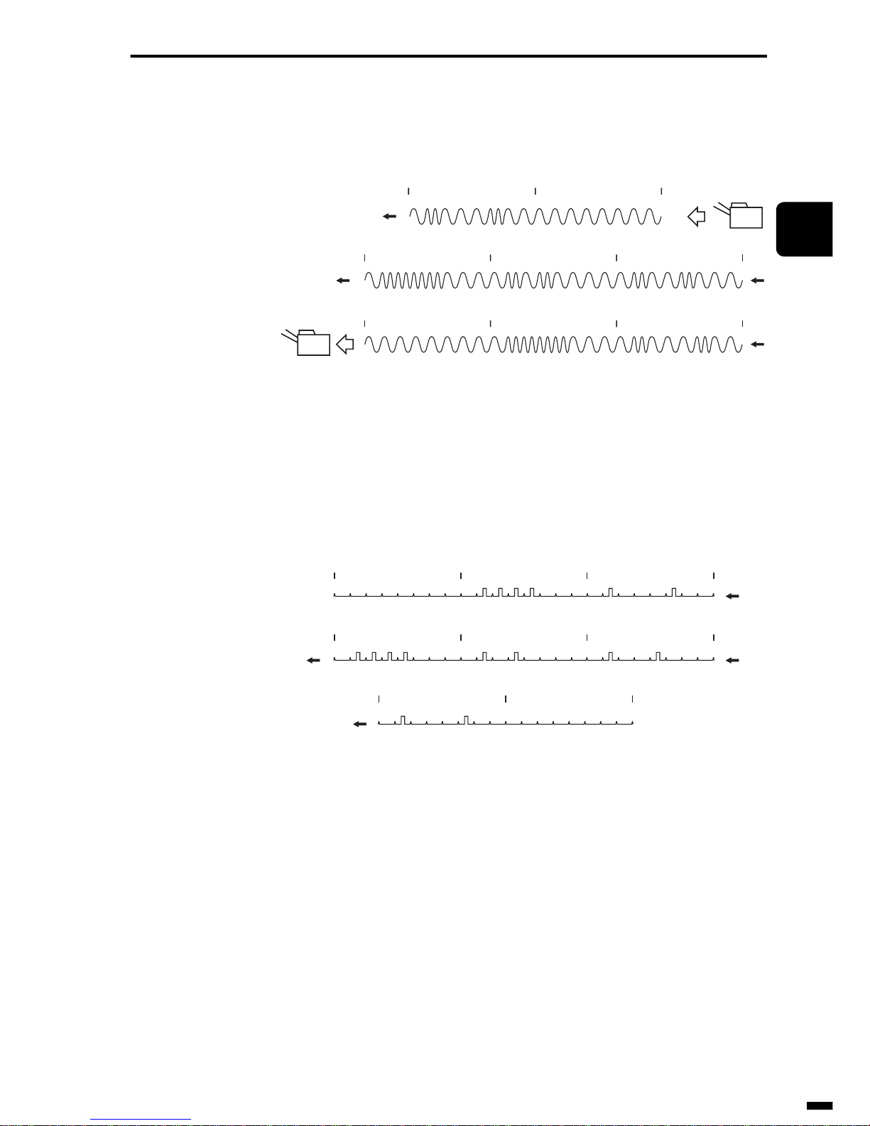
The picture signals are modulated. (This figure shows an example of frequency modulation.)
Fig. 2-6 Modulation
High level signal
Low level signal
a
b
c
d
e
f
g
h
12345678
a
b
c
d
e
f
g
h
12345678
High lev elsignal
Low level signal
High frequency
Low frequency
12345678
a
b
c
d
e
f
g
h
Page 47
2–11
1
2
3
4
5
6
ït
çi
GENERAL DESCRIPTION OF A FACSIMILE
(5) Transmission/Reception
Image signals are transmitted in the order of lines a, b through h.
Fig. 2-7 Transmission/Reception
(6) Demodulation
Image signals a through h are sequentially demodulated into the electrical
signals that represent black and white pixels.
Fig. 2-8 Demodulation
abc
def
gh
Reception
Transmission
FAX
FAX
def
gh
abc
Page 48

GENERAL DESCRIPTION OF A FACSIMILE
2–12
(7) Reassembly of pixels
Demodulated electrical signals are sequentially reassembled.
Fig. 2-9 Reassembly of pixels
(8) Reproduction of image
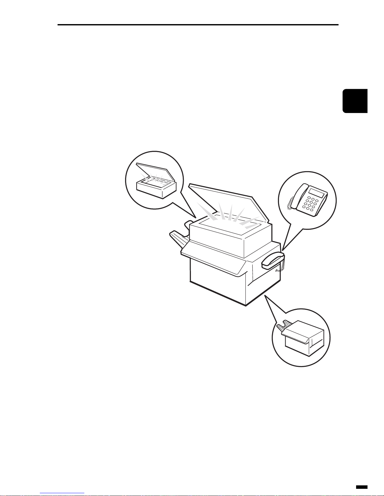
The black and white image information is printed on recording paper
according to the electrical signals to reproduce a copy of the original picture.
Fig. 2-10 Reproduction of Image
a
b
c
d
e
f
g
h
12345678
a
b
c
d
e
f
g
h
12345678
Page 49
2–13
1
2
3
4
5
6
ït
çi
GENERAL DESCRIPTION OF A FACSIMILE
2. STRUCTURE OF A FACSIMILE
Now, let’s take a look at the actual structure of a facsimile.
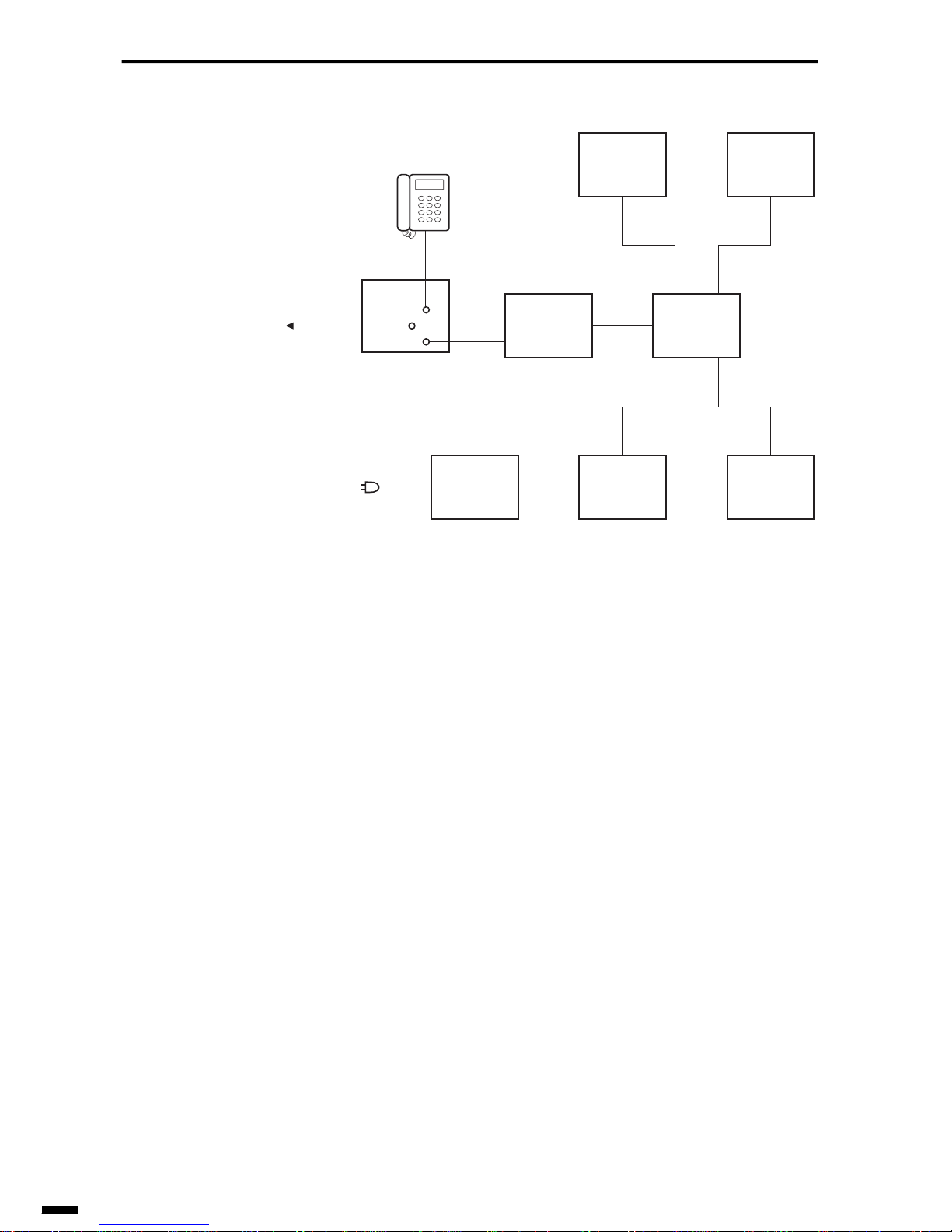
Simply speaking, we could say that a facsimile is structured by integrating
a scanner (reading section) and printer (recording section) in a telephone,
and providing it with a communications function (modem) for handling
data exchange transactions with the other party via a telephone line(NCU
board).
Fig. 2-11 Structure of a Facsimile
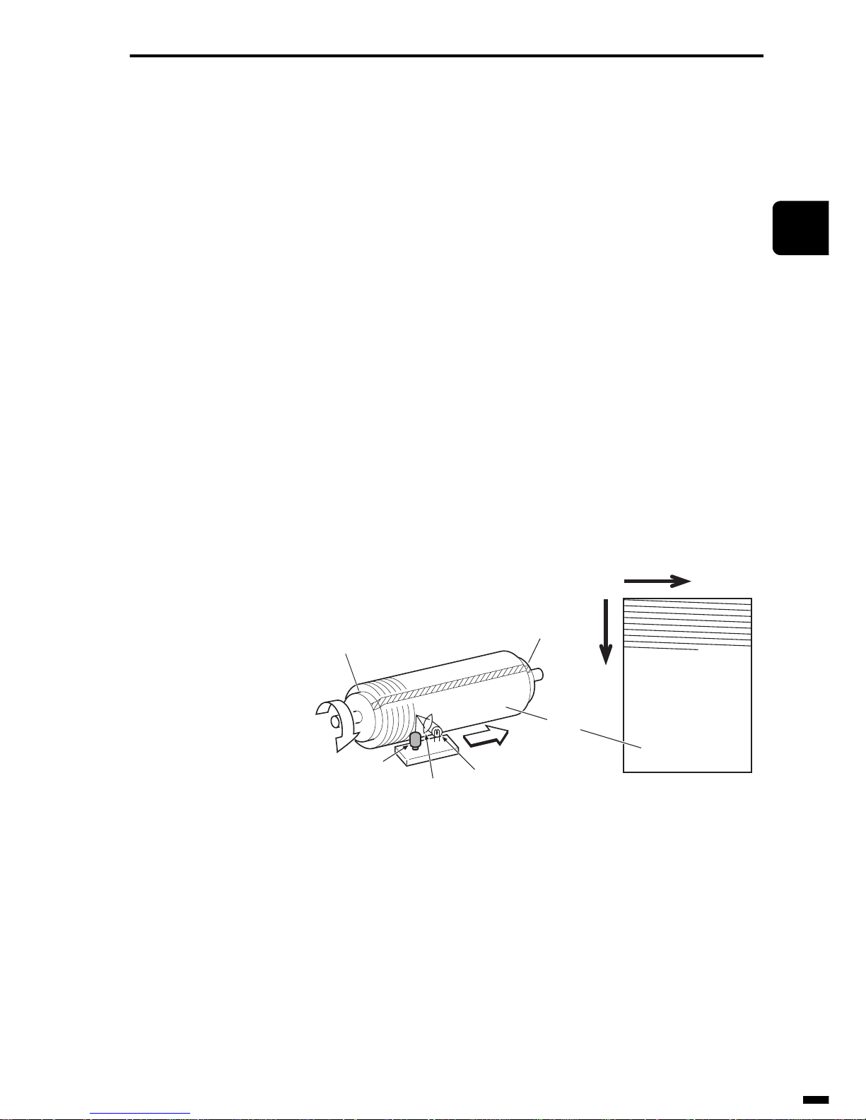
Fig. 2-12 is a block diagram of these facsimile’s electric systems.
Page 50
GENERAL DESCRIPTION OF A FACSIMILE
2–14
Fig. 2-12 Block Diagram of Facsimile Electric System
The facsimile has a system control section comprising mainly a CPU, and
the reading section, recording section, modem and other mechanisms are
connected to its periphery.
The system control section comprises mainly a CPU, and has a ROM
(Read Only Memory) in which facsimile operations are programmed, and
memory area for storing image data and other data such as telephone numbers. The main functions of the system control section include scanning
control for accepting image data from the image sensor, drive control for
driving the motors and other moving parts, recording control for operating
the recording section, image data control for transmitting image data to the
modem and receiving image data, and modem control for operating the
modem in various other ways.
Let’s take a look at the main mechanisms in a little more details.
System
control unit
Operation
unit
Reading
section
Sensors
Recording
section
Modem
NCU
board
Power
supply unit
AC power
supply
Telephone
line
Page 51
2–15
1
2
3
4
5
6
ït
çi
GENERAL DESCRIPTION OF A FACSIMILE
2.1 Reading Section
The role of the reading section is to read the document(s) to be transmitted
to the other party and convert images into electrical signals.
For those used to operating a personal computer, calling the reading section an “image scanner” will be easier to understand.
Reading methods can be broadly classified into the following two methods.
2.1.1 Cylinder scanning
This scanning method uses a single photosensor and a rotating cylinder
that enables two-dimensional movement around the sensor.
The document is wound around the cylinder , and the photosensor is moved
in the direction of the cylinder shaft while the cylinder is rotated.
The direction that the document rotates is the horizontal scanning and the
direction that the photosensor moves is the vertical scanning.
This scanning method was used when facsimiles first appeared on the market, and is now no longer used.
Fig. 2-13 Cylinder Scanning
Horizontal
scanning
Document
contact surface
Document
Vertical scanning
Illuminating
light source
Lens
Photosensor
Horizontal
scanning
Cylinder
Vertical
scanning
Page 52
GENERAL DESCRIPTION OF A FACSIMILE
2–16
2.1.2 Flat-bed scanning
By this scanning method, a photosensor comprising linearly arranged sensors is moved in the vertical scanning direction to read the document or the
document itself is moved while being scanned by the photosensor.
By this method, the required number of photosensors for reading a single
line in the vertical scanning direction is moved to read a single line of the
document, and the reading position is moved one line at a time in the hori-
zontal scanning direction to read the entire document. There are two meth-
ods of movement in the horizontal direction: movement of the document or
movement of the photosensor itself.
CCD image sensors and contact sensors are two types of photosensor used
in flat-bed scanning.
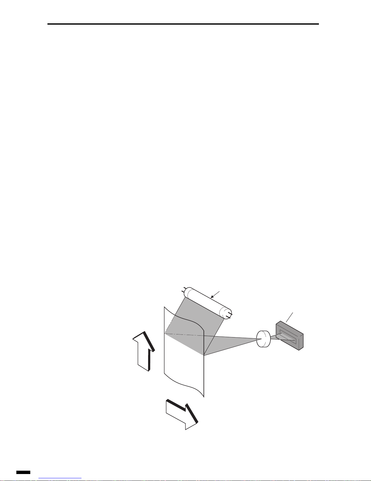
(1) CCD image sensor system
Though the CCD image sensor itself is small, the optical path up to the
document must be lengthened, which makes CCD image sensors unsuitable for downsizing of reading sections. Nevertheless, this system has the
advantage over a contact sensor as its reading speed is faster than that of a
contact sensor, and enlargement and reduction processing is performed
mechanically. For this reason and for the fact that it demonstrates little
image deterioration, this system is widely used on large-size machines
even now.
Fig. 2-14 Flat-bed Scanning (CCD image sensor system)
Fluorescent lamp
CCD image sensor
Lens
The CCD image sensor reads one horizontal scanning line at a time.
Document
Document reading direction
Document feed
direction
Page 53
2–17
1
2
3
4
5
6
ït
çi
GENERAL DESCRIPTION OF A FACSIMILE
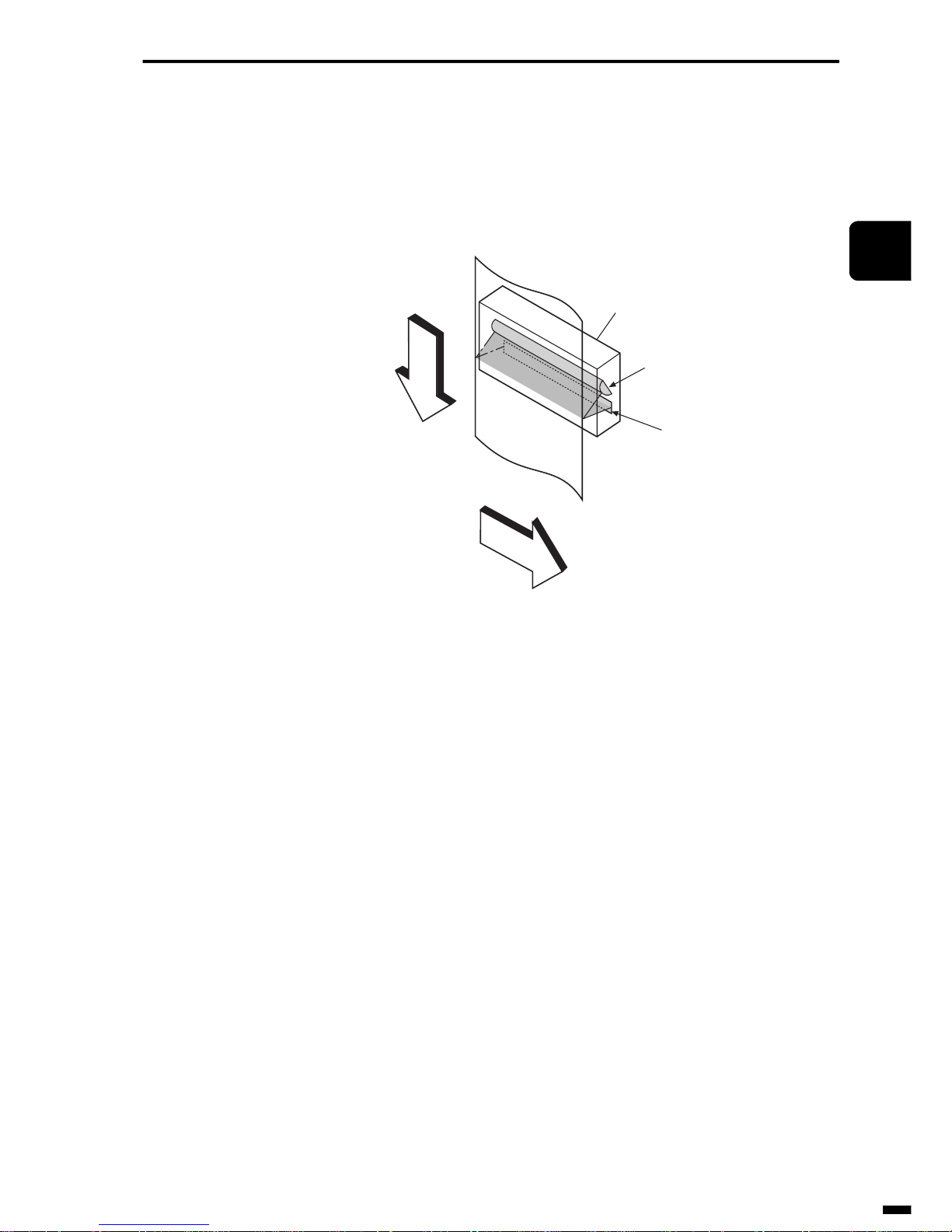
(2) Contact sensor system
Though contact sensors are inferior to CCD image sensors in terms of
reading speed, contact sensor systems have the advantage that they can be
downsized. This system is used on small-, medium- and large-size
machines accompanying progresses in image-processing technology.
Fig. 2-15 Flat-bed Scanning (contact sensor system)
Contact sensor
The phototransistor in the contact sensor
reads one horizontal scanning line at a time.
Document
Document reading direction
Document feed
direction
LED array (photoemitter)
Phototransistor array
(photosensor)
Page 54
GENERAL DESCRIPTION OF A FACSIMILE
2–18
2.2 Recording Section
This is the so-called printer.
Here, picture data that is sent from the other party is printed on paper.
Generally, the following three methods are used for recording on a facsimile.
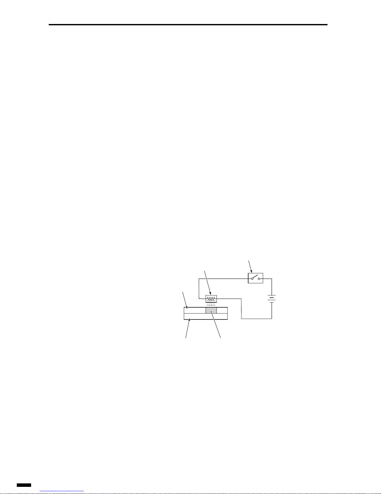
2.2.1 Thermal recording method
This recording method uses paper (heat-sensitive paper) that has been
coated with a color-forming layer. Color is formed on this paper by the
action of heat on its surface. Heat is generated by a thermal element (thermal head) that is held in contact against the surface of the color-forming
layer.
This recording method has a drawback in that it is not suitable to long periods of storage as heat-sensitive paper fades with time. However, it has the
advantages that facsimiles can be made compact due to its simple structure
and is maintenance-free. For these reasons, it is the most widely used of
the recording methods in entry facsimile models such as facsimiles for
household use.
Fig. 2-16 Thermal Recording Method
Surface
color-forming
layer
Thermal element
Image signal
Color formationPaper
Page 55
2–19
1
2
3
4
5
6
ït
çi
GENERAL DESCRIPTION OF A FACSIMILE
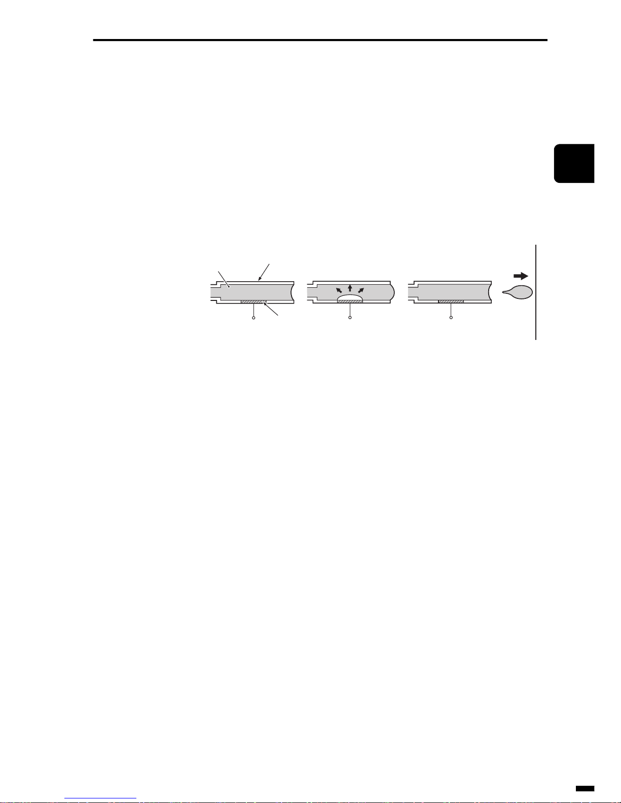
2.2.2 Ink jet recording method
By this method, particles of ink are dispensed from nozzles to adhere to
the recording paper.
As plain paper is used as the recording paper, this method has the advantage that recording paper that has been received can be written and
stamped on. It is also ideal for storage as it is not curled up and does not
discolor. In spite of the fact that it uses plain paper to record on, its structure is relatively simple, which allows facsimiles to be made compact. For
this reason, it is being used more and more in household facsimiles.
Fig. 2-17 Ink Jet Recording Method
Recording
paper
Nozzle
Ink
Heater element
Page 56
GENERAL DESCRIPTION OF A FACSIMILE
2–20
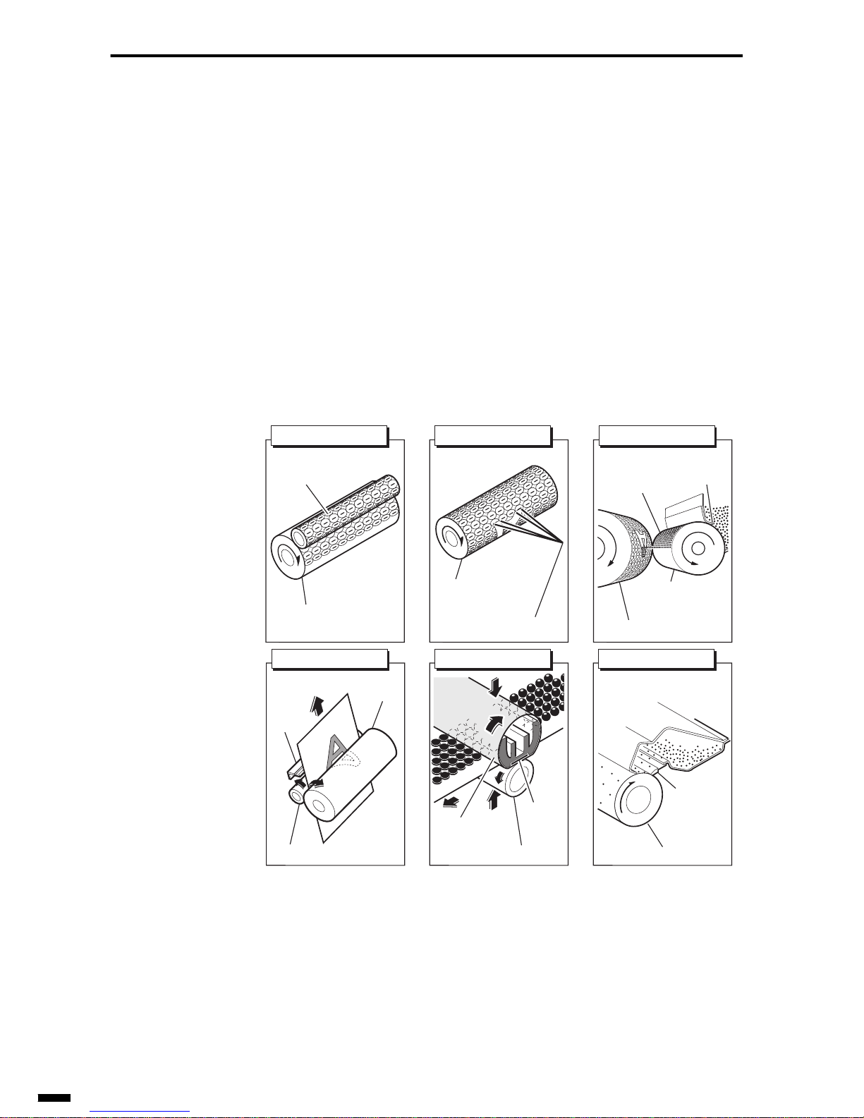
2.2.3 Electrophotographic method
Canon is putting onto the market facsimiles that use a LASER beam
printer (LBP) engine.
By this method, the pattern to be recorded is exposed on the surface of a
photosensitive drum by a LASER beam, and toner is made to adhere on
that pattern. Next, the toner on the photosensitive drum is transferred to the
recording paper, and is then fixed on the paper by heat and pressure. This
series of operations is called the “print process.”
This recording method has the same advantages as the ink jet recording
method as it uses plain paper as the recording paper. It also has an extra
feature in that it records at high speed. However, as its structure is relatively elaborate and expensive, it is widely used in medium- and high-class
facsimiles.
Fig. 2-18 Electrophotographic System
(4) Transfer
Photosensitive
drum
Transfer charging roller
static
charge
eliminator
(1) Primary charging
Primary charging
roller
Photosensitive drum
(3) Developing
Developing
cylinder
Photosensitive drum
Minuscharged
toner
Blade
Photosensitive
drum
(2) Exposure
Laser beam
Fixing film
Fixing pressure roller
Fixing
heater
(5) Fixing
Cleaner
blade
(6) Cleaning
Photosensitive drum
Page 57
2–21
1
2
3
4
5
6
ït
çi
GENERAL DESCRIPTION OF A FACSIMILE
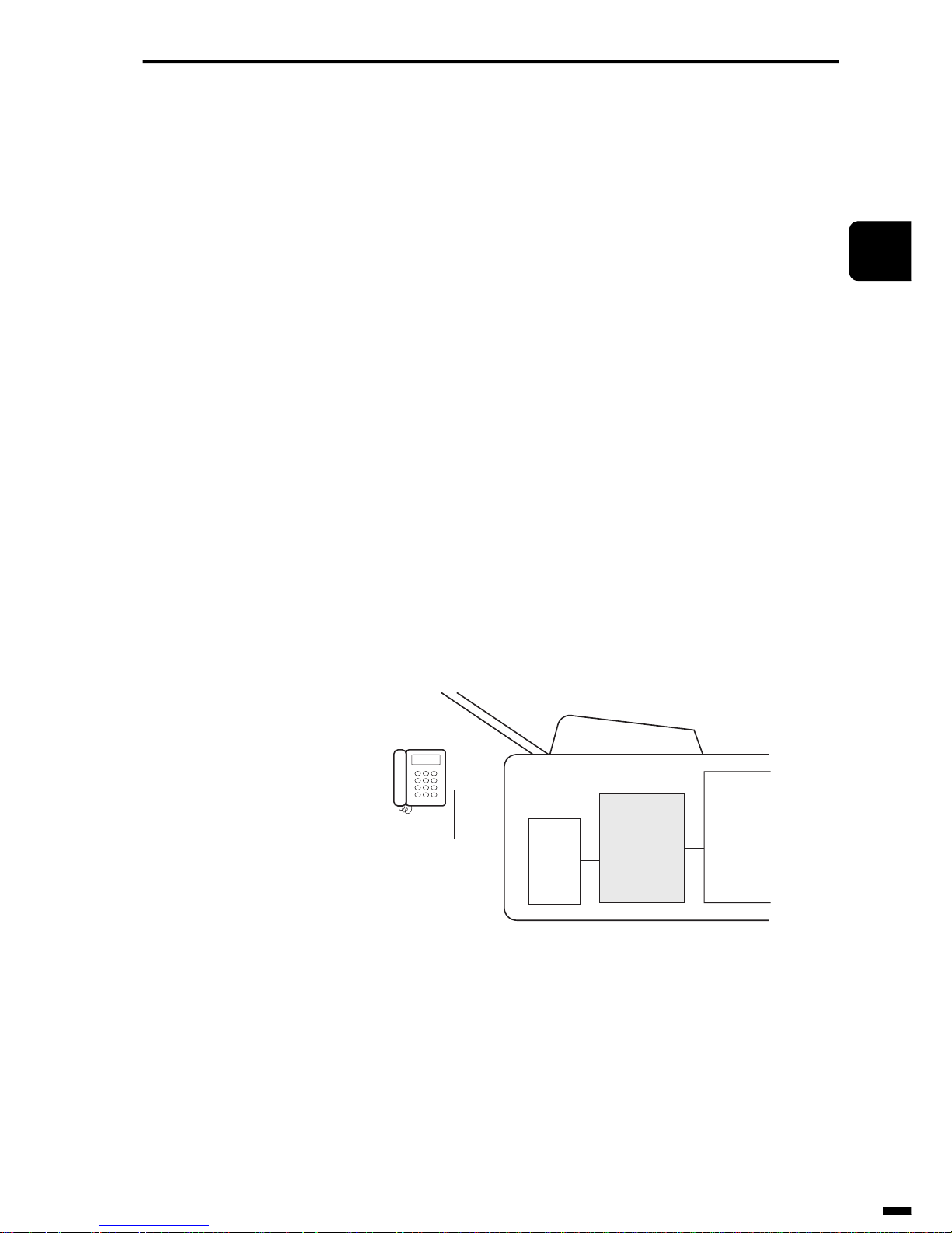
2.3 MODEM
Facsimiles must transmit image signals (digital signals) of scanned documents to other parties via telephone lines (analog lines). For this reason,
the transmitting facsimile must convert these digital signals to analog signals and transmit them out onto the telephone line. This conversion is
called “modulation.” Alternatively, the receiving facsimile must convert
the analog signals (modulated signals) that arrive ov er the telephone line to
digital signals. This conversion is called “demodulation” due to the fact
that “modulated signals are restored to their original state.” A device that
modulates signals is called a “modulator,” and a device that demodulates
signals is called a “demodulator.” A device that can perform both modulation and demodulation is called a “MODEM” (MOdulator and DEModulator). As the frequency bandwidth of a telephone line is between 300 to
3,400 Hz, the modulation methods indicated below recommended by ITU-
T are used as the G3 facsimile modem to transmit image signals efficiently
and at high speed to the other party within that frequency bandwidth.
• PSK: Phase Shift Keying
• QAM: Quadrature Amplitude Modulation
FSK (Frequency Shift Keying) is used as a modulation method for procedure signals required for transmitting image signals.
Fig. 2-19 Modem Location
Telephone line
T1
T2
L1
L2
NCU
MODEM
System
control
setion
Facsimile
board
Page 58
GENERAL DESCRIPTION OF A FACSIMILE
2–22
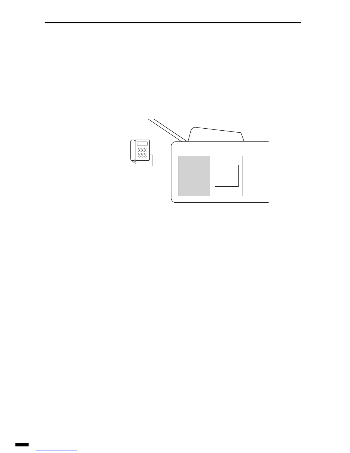
2.4 NCU board (Network Control Unit board)
The NCU board is a kind of relay board for interfacing the telephone line
to facsimile equipment. This unit detects the calling identification signal
(for ringing the bell on the called party’s telephone) that arrives from the
telephone line to perform control of connection to the telephone or the
modem.
Fig. 2-20 NCU board Location
2.5 System Control Section
The role of this control section includes the control of all facsimile devices
(mainly the CPU, program ROM and memory), data processing and sa ving
of data.
Generally, the system control section corresponds to the electrical circuit
boards called the SCNT board or IP board mounted on Canon facsimiles.
Telephone line
T1
T2
L1
L2
System
control
section
Facsimile
MODEM
NCU
board
Page 59

2–23
1
2
3
4
5
6
ït
çi
GENERAL DESCRIPTION OF A FACSIMILE
3. THE FUTURE OF FACSIMILES
The facsimiles we have discussed so far only transmit and receive blackand-white images over telephone lines. How will facsimiles look in the
future?
This section describes color facsimiles, LAN-networked facsimiles and
Internet facsimiles whose use is expected to expand in the future.
3.1 Color Facsimiles
Color facsimile products that use proprietary image data compression
methods and proprietary communications protocol are already on the market. As only low-resolution image can be tarnsmitted, and only proprietary
methods are used, communications is possible only between models of
facsimiles made by the same manufacturer.
In the future, color facsimile communications using image data compression methods and communications protocol that conform to ITU-T recommendations will become standard due to the appearance of color facsimiles
capable of tarnsmitting high-resolution color images to facsimiles made by
other manufacturers.
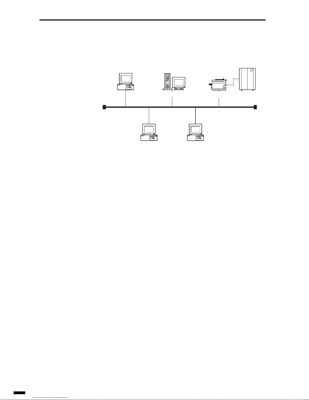
3.2 LAN-networked Facsimiles
LANs (Local Area Networks) in offices are spreading at a rapid rate. As a
result, various trends are beginning to emerge. These include the remote
control of facsimile functions. For example, a possible application could
be to call up a letter drafted on a networked personal computer, then call
up a facsimile networked on the same LAN (let’s call this facsimile a
“LAN-FAX”), and then transmit that letter directly to a specific party from
your personal computer. This will allow people to transmit documents to
other parties directly without having to go to the lengths of printing out the
letter on paper. The same method could be applied to receiving documents.
First of all, the document to receive (image data) that is transmitted to the
LAN-FAX is temporarily stored on the LAN-FAX itself or on a LAN-networked server. The content of these received document pages can also be
checked on the personal computer’s screen, and only the required pages of
the document can be printed out on paper.
An application different from a general facsimile application is also possible. Facsimiles originally are machines that have both a printer and an
image scanner. These functions could also be used effectively on the LAN;
Page 60
GENERAL DESCRIPTION OF A FACSIMILE
2–24
you could use the facsimile from a personal computer as a network printer
or as an image scanner. Such facsimiles have already started appearing on
the market.
Fig. 2-21 LAN-networked Facsimiles
3.3 Internet Facsimiles
The mere mention of the Internet makes people think of e-mail and home
pages. The Internet is in the process of becoming an indispensable item
just like the telephone in society today. Facsimiles too are being required
to be connected to the Internet in addition to telephone lines. If we consider that “What is important for a facsimile is to deliver image information (messages) to the other party,” then we will see that the Internet has
similar kinds of services. The message exchange service on the Internet is
e-mail. That is, if we successfully integrate e-mail and facsimiles, then the
facsimile will come to be usable on the Internet.
The specifications of an Internet facsimile have been under review since
1996 by the IETF on the premise that e-mail services will be incorporated.
Standards centering around RFC 2305 were determined in March of 1998,
and these were turned into recommendation T.37 (simple mode) in July
1998 with the cooperation of the ITU-T. These specifications define ser-
vices for specifying mail addresses from facsimile machines connected to
the network for delivering information to other parties or alternatively
delivering e-mail to facsimiles by. If Internet facsimiles are used, we can
use facsimiles to transmit urgent business as e-mail. Also, mobile users
will also be able to receive all facsimiles addressed to themselves as email, so facsimiles will come to be transmitted and received anywhere.
Full-mode specifications and real-time type T.38 recommendations have
also been added.
Server
LAN
LAN-FAX
Exchange
Page 61

2–25
1
2
3
4
5
6
ït
çi
GENERAL DESCRIPTION OF A FACSIMILE
Either way , we believe that facsimiles will be transformed from being standalone facsimile machines, and will enter the market as facsimiles to be
connected to LANs and the Internet, as facsimiles for connection to network systems. For this reason, conventional knowledge of telephone lines
and facsimiles will not be sufficient for handling these products. Improving and acquiring knowledge of LAN technology, Internet technology and
LAN-related networks will prove to be all the more important from now
on.
Page 62

Notes
2–26
Page 63

CHAPTER
3
1
2
3
4
5
6
ït
çi
3 READING SECTION
1. INTRODUCTION...................................................................... 3-2
2. READING METHODS.............................................................. 3-3
2.1 Sheet Reading Method ................................................... 3-3
2.2 Book Reading Method..................................................... 3-4
2.3 ADF Type ........................................................................ 3-4
3. CONTACT SENSOR..............................................................3-10
3.1 Structure of Contact Sensor.......................................... 3-10
3.2 Features of Contact Sensor ..........................................3-10
4. IMAGE DATA PROCESSOR..................................................3-14
4.1 Various Image Data Processing................................... 3-14
Page 64

READING SECTION
3–2
1. INTRODUCTION
This chapter describes the reading section of the facsimile.
At the reading section, a document comprising two or more sheets is fed
one sheet at a time to the image sensor (e.g. contact sensor) where it is
read, and the resulting image data undergoes image processing.
Fig. 3-1 Reading Section
Contact sensor
Document
feed path
To image
processing section
Page 65
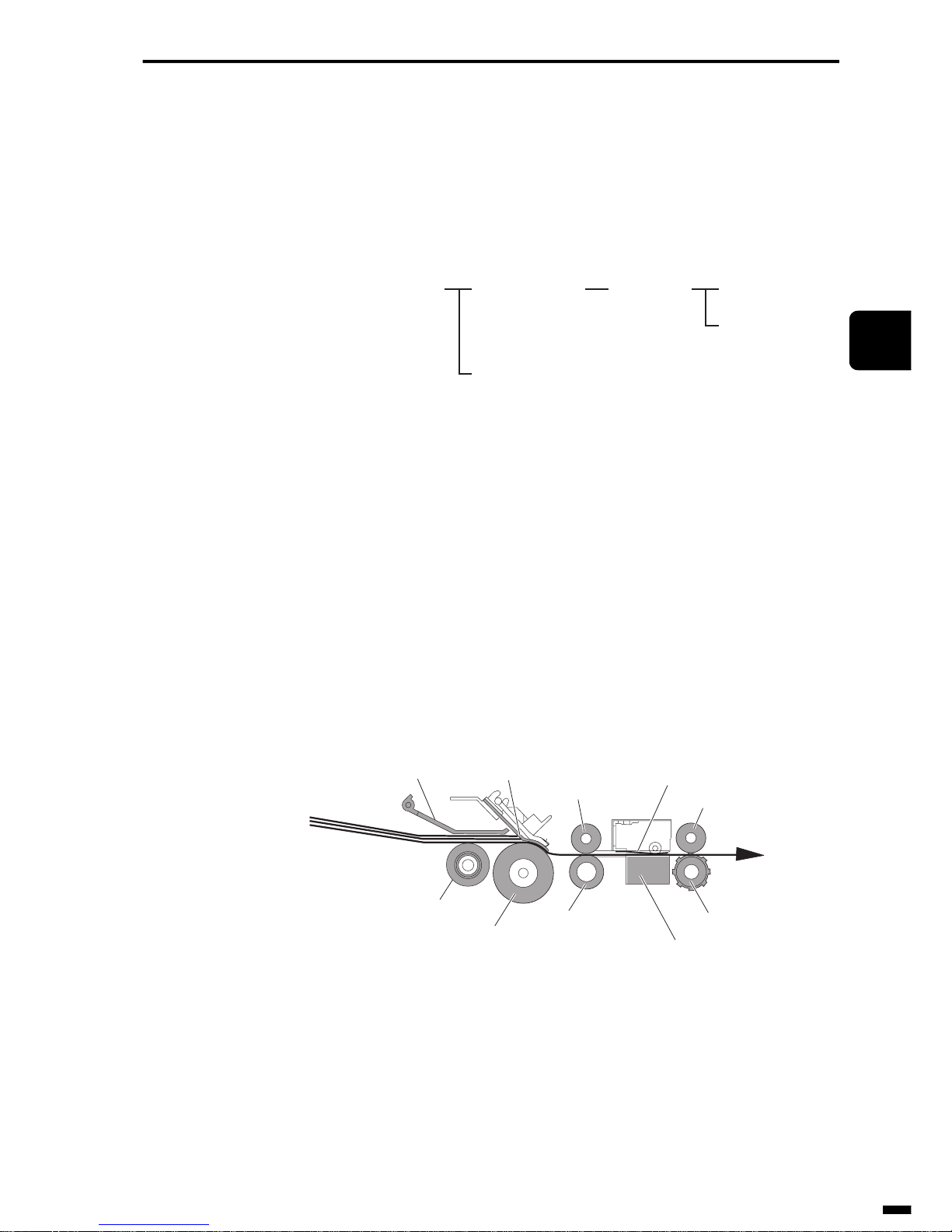
3–3
1
2
3
4
5
6
ït
çi
READING SECTION
2. READING METHODS
There are two types of reading methods, sheet reading method and book
reading method. There are a further two types of reading methods for the
sheet reading method, flat-bed type and drop-in type.
Fig. 3-2 Types of Reading Methods
2.1 Sheet Reading Method
The general operation of sheet reading is as follows.
The document is fed up to the separation roller and separation guide by the
forwarding roller.
Next, the separation roller and separation guide separate the document one
sheet at a time from the bottommost sheet. After the document sheets are
separated, they are fed to the contact sensor by the feed roller. After the
document is read by the contact sensor, it is output by the eject roller.
Fig. 3-3 Sheet Reading
Reading method Sheet reading
method
ADF type
Flat-bed type
Drop-in type
Book reading
method
Document
Document pressure
plate
Separation guide
Upper feed roller
White mylar sheet
Upper eject roller
Document feed path
Forwarding roller
Separation roller
Feed roller
Contact sensor
Eject roller
Page 66
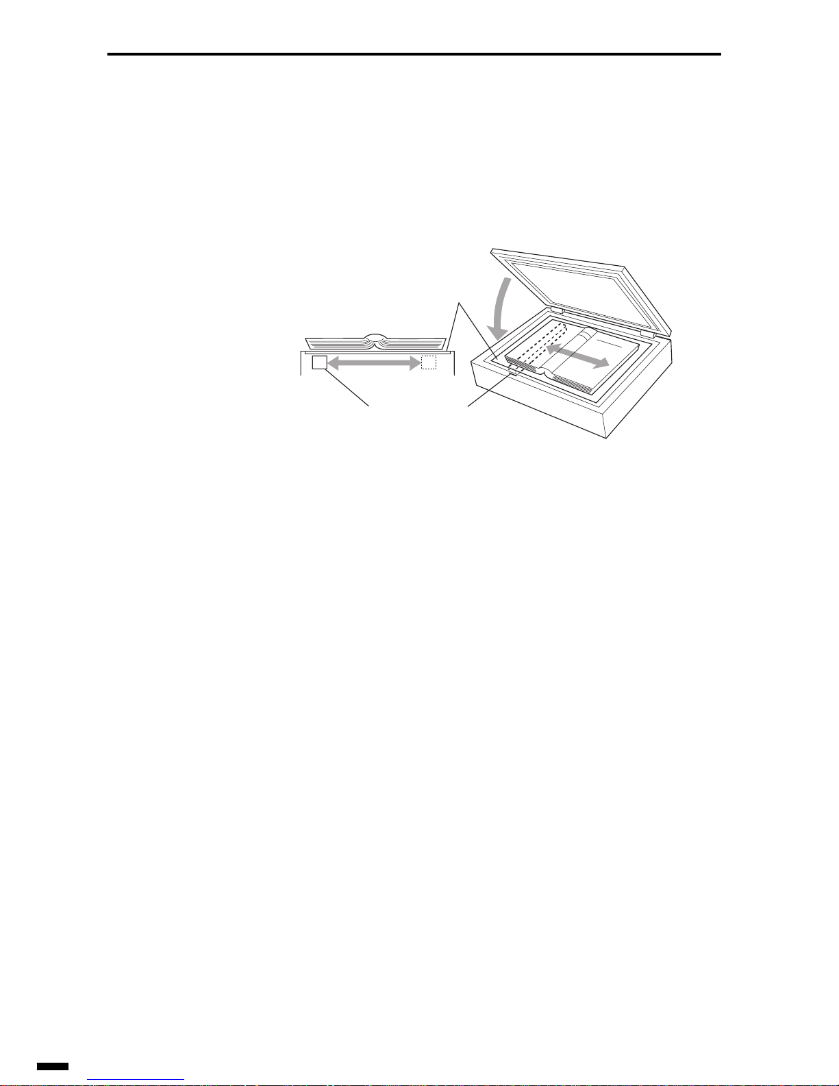
READING SECTION
3–4
2.2 Book Reading Method
Book reading is a method where the document (thick document) is placed
on the copyboard glass and is read by the contact sensor. This sensor is
moved backwards and forwards in the v ertical scanning direction along the
guide shaft by motor drive transmitted to the belt via gears.
Fig. 3-4 Book Reading Method
2.3 ADF Type
One of the sheet reading methods is the ADF (Auto Document Feeder)
separation method. There are two main ADF types, flat-bed type and dropin type.
2.3.1 Flat-bed type
A feature of this ADF type is consistent performance during loading of
documents, which makes it suitable for loading a document comprising
many sheets.
On the other hand, howev er, it costs more as a forwarding roller is required
in the mechanism and more installation space is required. Double feeding
sometimes occurs due to over-insertion of document sheets when the document is loaded, or, alternati v ely, sheets being non-fed due to an insufficient
amount of sheets being loaded.
• Explanation of flat-bed type operation
By this type of ADF mechanism, drive from the document feed motor is
transmitted to the rollers required for document forwarding, separation,
feed, and eject via gears and belts.
To control ADF operation, the CPU counts the number of step pulses of
the document feed motor, and two photointerrupter type sensors, document
sensor (DS) and document edge sensor (DES), installed on the actuator
arm detect the feed state of the document.
Copyboard glass
Contact sensor
Page 67
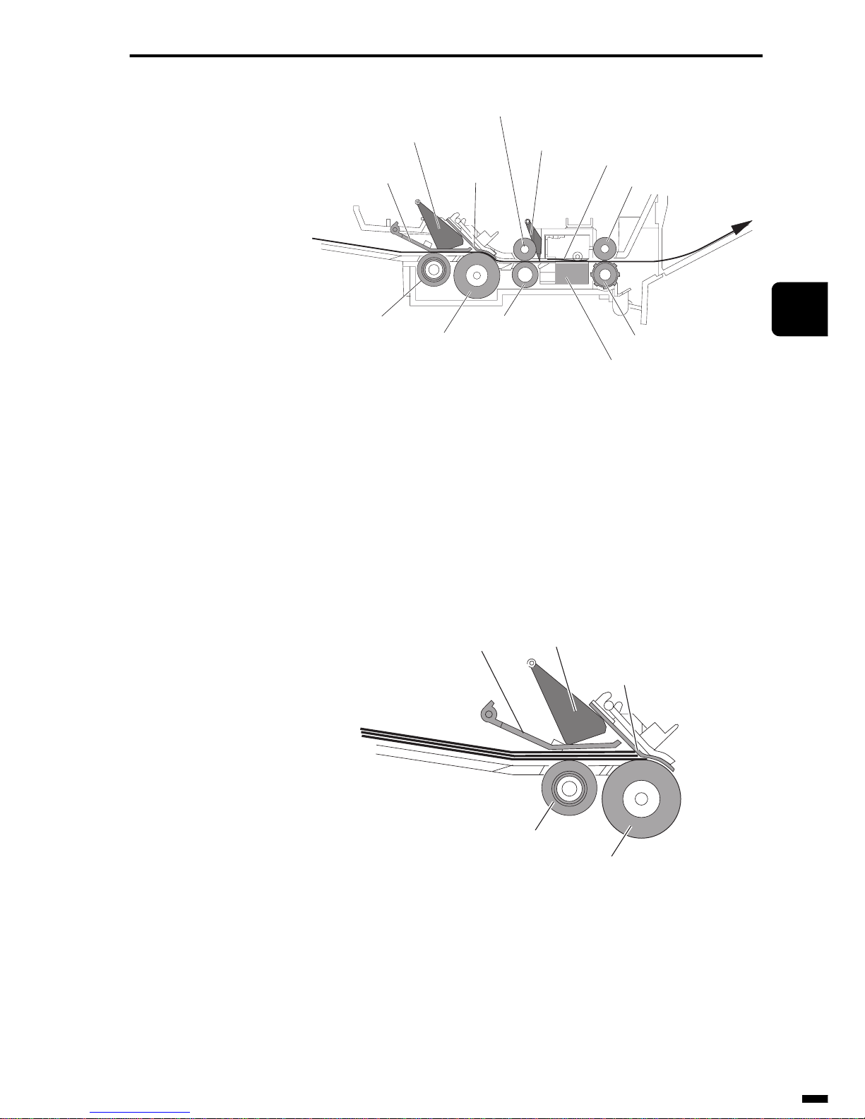
3–5
1
2
3
4
5
6
ït
çi
READING SECTION
Fig. 3-5 Flat-bed type ADF
Now, let’s take a look at which operations are performed.
(1) Document forwarding operation
When the document is inserted in the ADF section and pushes up the actuator on the document sensor, the forwarding roller picks up the document
as far as the separation roller and separation guide.
Fig. 3-6 Document Pickup
Document feed path
Document pressure
plate
Document sensor
actuator
Separation
guide
Upper feed roller
Document edge
sensor actuator
White mylar sheet
Upper eject roller
Forwarding roller
Separation roller
Feed roller
Contact sensor
Eject roller
Document
Document pressure
plate
Document sensor
actuator
Separation guide
Forwarding roller
Separation roller
Page 68
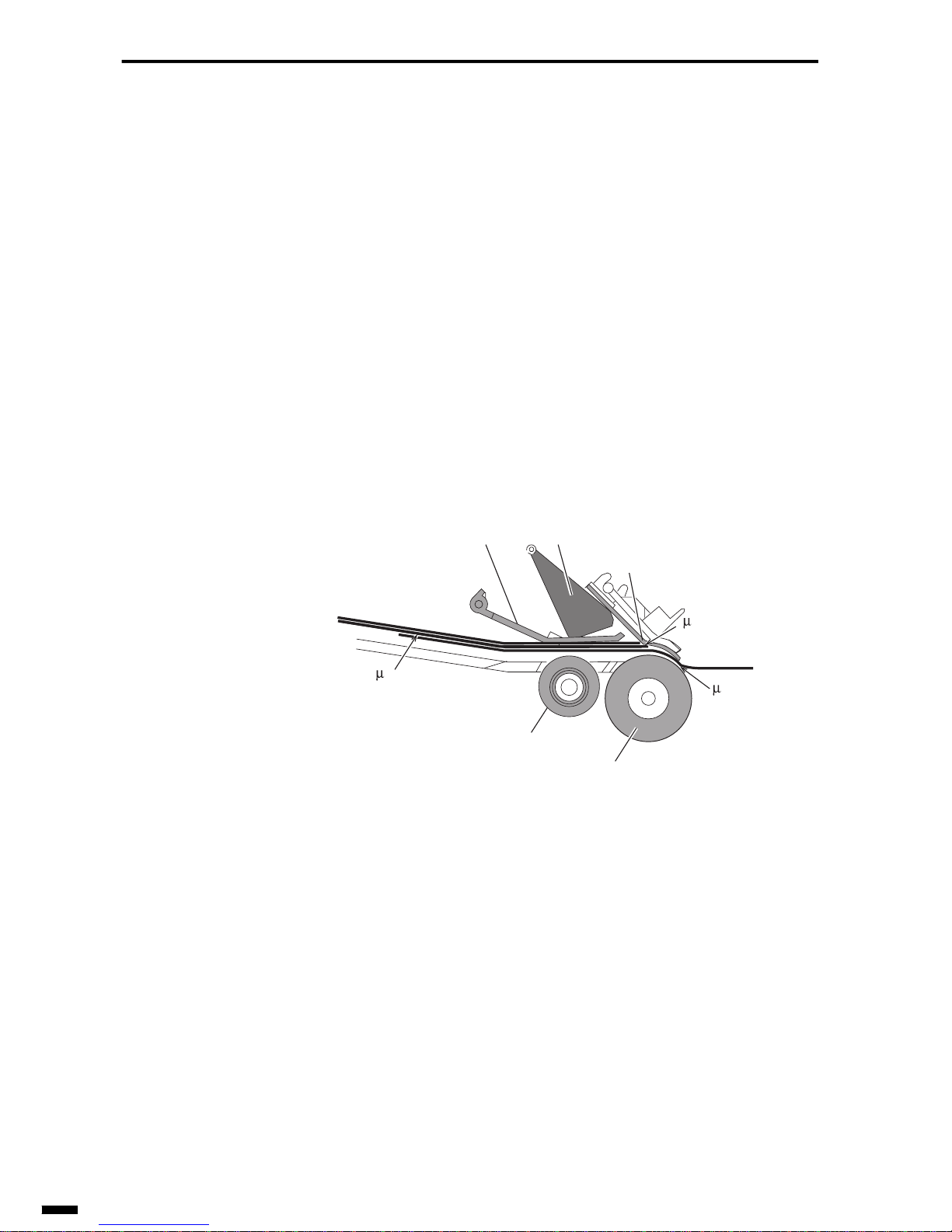
READING SECTION
3–6
(2) Document separation operation
After document forwarding, the document is fed out into the document
feed section one sheet at a time from the bottommost sheet by the separation roller and separation guide.
Entry of the remaining document sheets into the document feed section is
prevented by the separation guide.
The relationship shown by the following equation is used for separated
document sheets.
If the friction coefficient between the document and separation roller is
taken to be µ1, the friction coefficient between the separation guide and the
document to be µ2, and the friction coefficient between two sheets of the
same document to be µ3, then the following relationship between these
three friction coefficients must be satisfied:
µ1 > µ2 > µ3
Fig. 3-7 Document Separation
(3) Document feed operation
After the document is separated, the document sheets are fed to the contact
sensor by the feed roller. When the leading edge of the document pushes
up the actuator of the document edge sensor located at the feed roller section, monitoring of the document length begins.
To prevent slack in document feed, the document feed roller is driven at a
speed faster than that of the document separation roller. In this state, however, the document is pulled out from the separation roller. As a result, the
spring clutch inside the separation roller pulls back both the separation
roller and forwarding roller simultaneously to equalize the feed speed of
the rollers in the entire document feed section.
Document
1
2
3
Document pressure
plate
Document sensor
actuator
Separation guide
Forwarding roller
Separation roller
Page 69
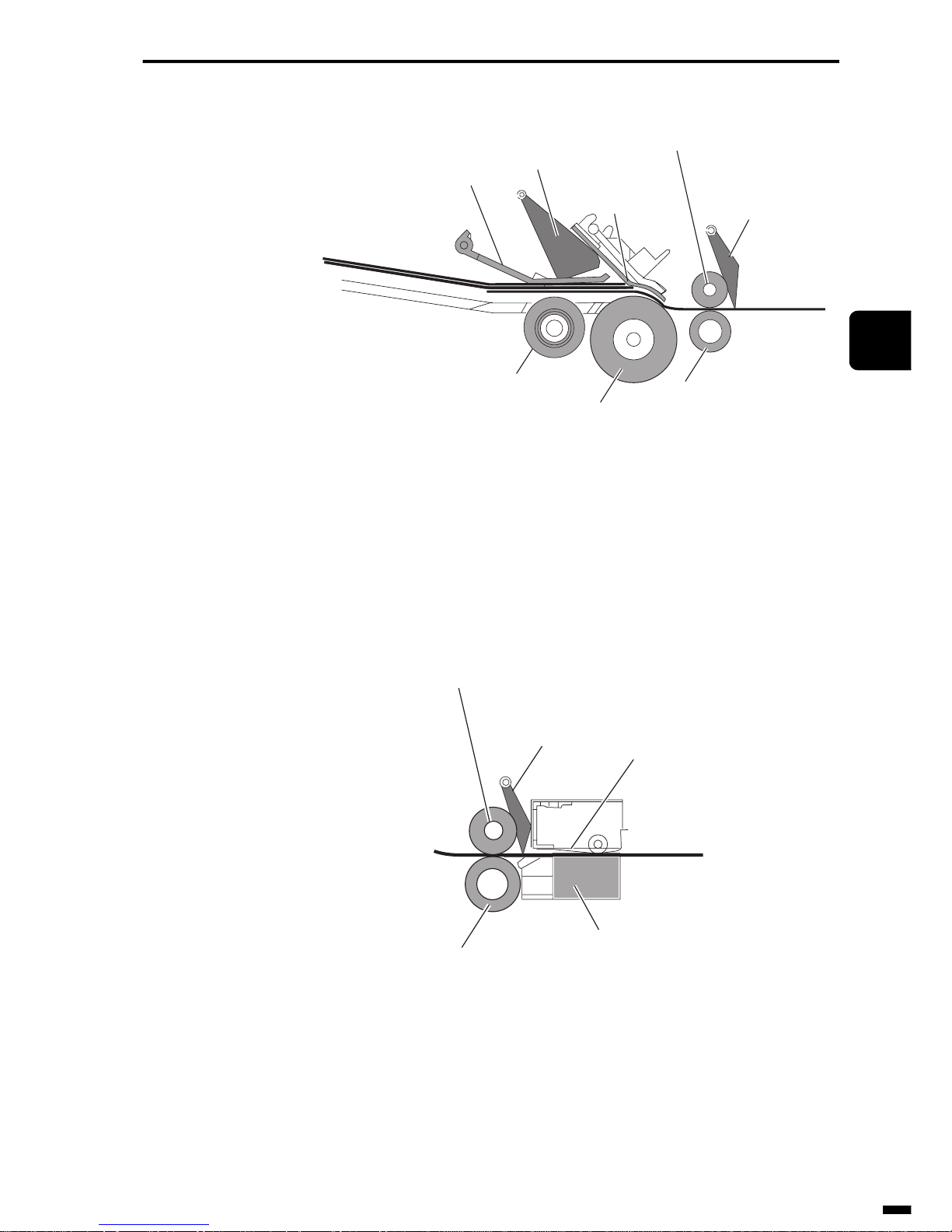
3–7
1
2
3
4
5
6
ït
çi
READING SECTION
Fig. 3-8 Document Feed
(4) Document reading operation
The document is held down from above by the white mylar sheet (white
reference sheet).
After the contact sensor has detected the white level from the white mylar
sheet, the document is passed over the contact sensor to be read.
Fig. 3-9 Document Reading
(5) Document eject operation
When the trailing edge of the document has passed out of the separation
roller, pulling back by the spring clutch inside the separation roller stops,
and the separation roller enters the separation process for the second document sheet. When the trailing edge of the document passes the feed roller,
Document
Document pressure
plate
Document sensor
actuator
Separation guide
Upper feed roller
Document edge
sensor actuator
Forwarding
Separation roller
Feed roller
White mylar sheet
Document edge
sensor actuator
Upper feed roller
Feed roller
Contact sensor
Document
Page 70
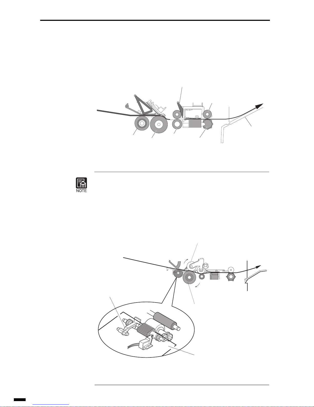
READING SECTION
3–8
the actuator on the document edge sensor drops to end monitoring of the
document length.
The document is then output onto the document tray by the eject rollers.
Fig. 3-10 Document Output
Flat-bed types recently are designed to be equipped with a document stopper to reduce feed problems caused by over-insertion of the document or
insufficient insertion.
Some types are also designed with separation rollers provided above and
below in place of the separation guide and with an inversion roller to
improve separation performance.
Fig. 3-11 Document Stopper
Document
Document edge
sensor actuator
Upper eject roller
Forwarding roller
Separation roller
Feed roller
Eject roller
Document tray
Document feed path
Upper separation roller
Separation roller
Document stopper
Document
Page 71
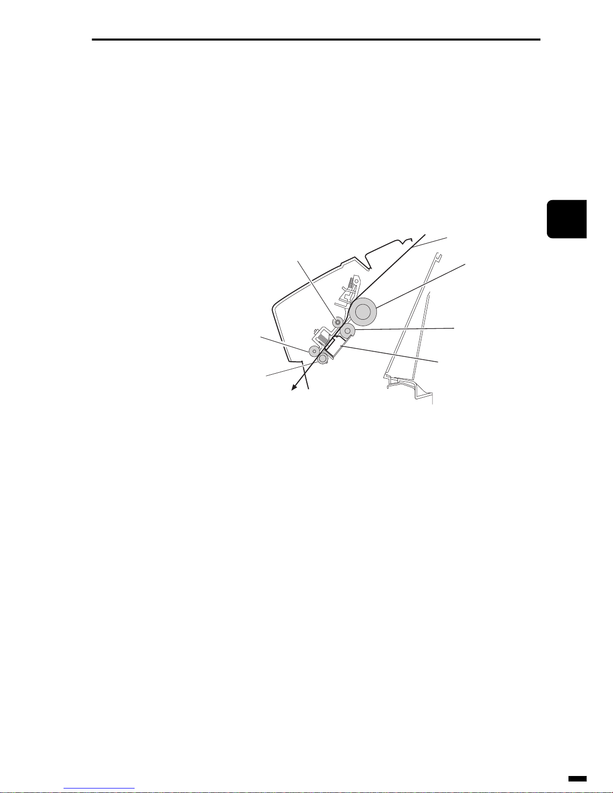
3–9
1
2
3
4
5
6
ït
çi
READING SECTION
2.3.2 Drop-in type
With this ADF type, performance when loading documents is inconsistent
due to its inclined document feed path. This sometimes results in the non-
feeding of sheets when a document comprising many sheets is loaded.
Also, as the document output direction is downwards, output documents
tend to stack poorly . On the other hand, however, it costs less as a forwarding roller is not required, and less installation space is required as the document feed path is inclined.
Fig. 3-12 Drop-in Type ADF
• Explanation of drop-in type operation
The same operations as for a flat-bed type ADF are performed for drop-in
type ADFs except that there is no document forwarding operation.
Feed roller
Upper feed roller
Upper eject roller
Separation roller
Eject roller
Contact sensor
Document feed path
Page 72

READING SECTION
3–10
3. CONTACT SENSOR
3.1 Structure of Contact Sensor
The structure of the contact sensor is designed to prevent dirt and dust
from collecting on the sensor surface or entering the inside. The inside of
the contact sensor comprises an LED array, contact glass, rod lens array
and photo-transistor array. The LED array emits the light for reading the
document, the contact glass refracts the light emitted from the LED array
to irradiate the document, the rod lens array picks up and channels the light
reflected from the document, and the photo-transistor array receives the
reflected light. (See Fig. 3-13)
3.2 Features of Contact Sensor
There are two types of contact sensor, the multi-chip type and the α-Si
(Amorphous Silicon) type.
The following describes the strengths and weakness of each type.
(1) Multi-chip type
• Unevenness of the sensor chip is less than that of the α-Si type.
• Image quality is good as the gamma characteristics are proportional.
• Documents can be read even if they rise off the glass surface slightly.
(This is dependent, though, on the performance of the rod lens array.)
• The document need not be held down by rollers. So, photographs need
not be pasted onto a sheet for reading.
• The density level differs among the sensor chips. So, a density difference may occur between sensor chips which may affect the image if
the density is not compensated.
(2) α-Si (amorphous silicon) type
• Costs can be reduced as a rod lens array is not required in the structure
of the contact sensor.
• The contact sensor can be designed to be thinner as the rod lens array
is not required.
• Light irradiated from the read surface of the copyboard glass is
reflected internally on the contact sensor to enter the photo-transistor
array. So, there is the possibility that even black originals will be
reproduced as gray.
Page 73

3–11
1
2
3
4
5
6
ït
çi
READING SECTION
• When the document rises up even slightly from the glass surface, that
section is read as black. So, the document must be held down by a
roller.
• As the document is pressed against the glass surface, there is the possibility that documents that tend to stick such as photographs cannot be
fed.
• As the roller is held in contact with the glass surface, it is difficult to
clean the contact sensor.
Page 74
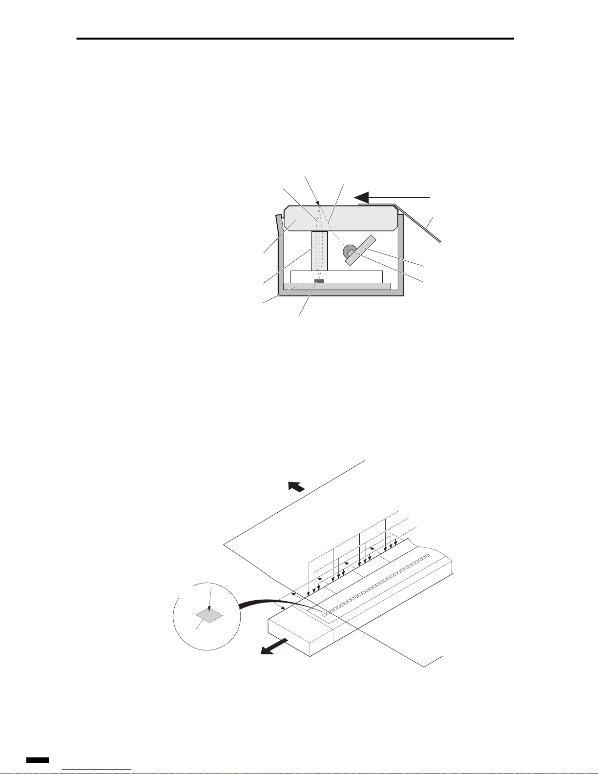
READING SECTION
3–12
3.2.1 Multi-chip type
The radiated light emitted from the LED array is reflected by the document, and passes through the rod lens array to be received by the phototransistor array.
Fig. 3-13 Multi-chip Type (cross-section view)
The sensor circuit board has a built-in drive r circuit for amplifying the output of the received light, and the output of that dri v er circuit is converted to
serial data to be transmitted to the system controller.
Fig. 3-14 Multi-chip Type
Reflected light
Reading surface
Radiated light
Document feed direction
Guide mylar sheet
LED circuit board
LED array
(light-emitting section)
Contact glass
Rod lens array
Sensor circuit board
Photo-transistor array
(light-receiving section)
Sensor
driver1
Sensor
driver2
Analog/serial output
Reading start signals
Sensor
driver3
Sensor
driver4
Clock signal
Sensor drive voltage
Document
Reflected
light
Sensor
Control
circuit
Page 75
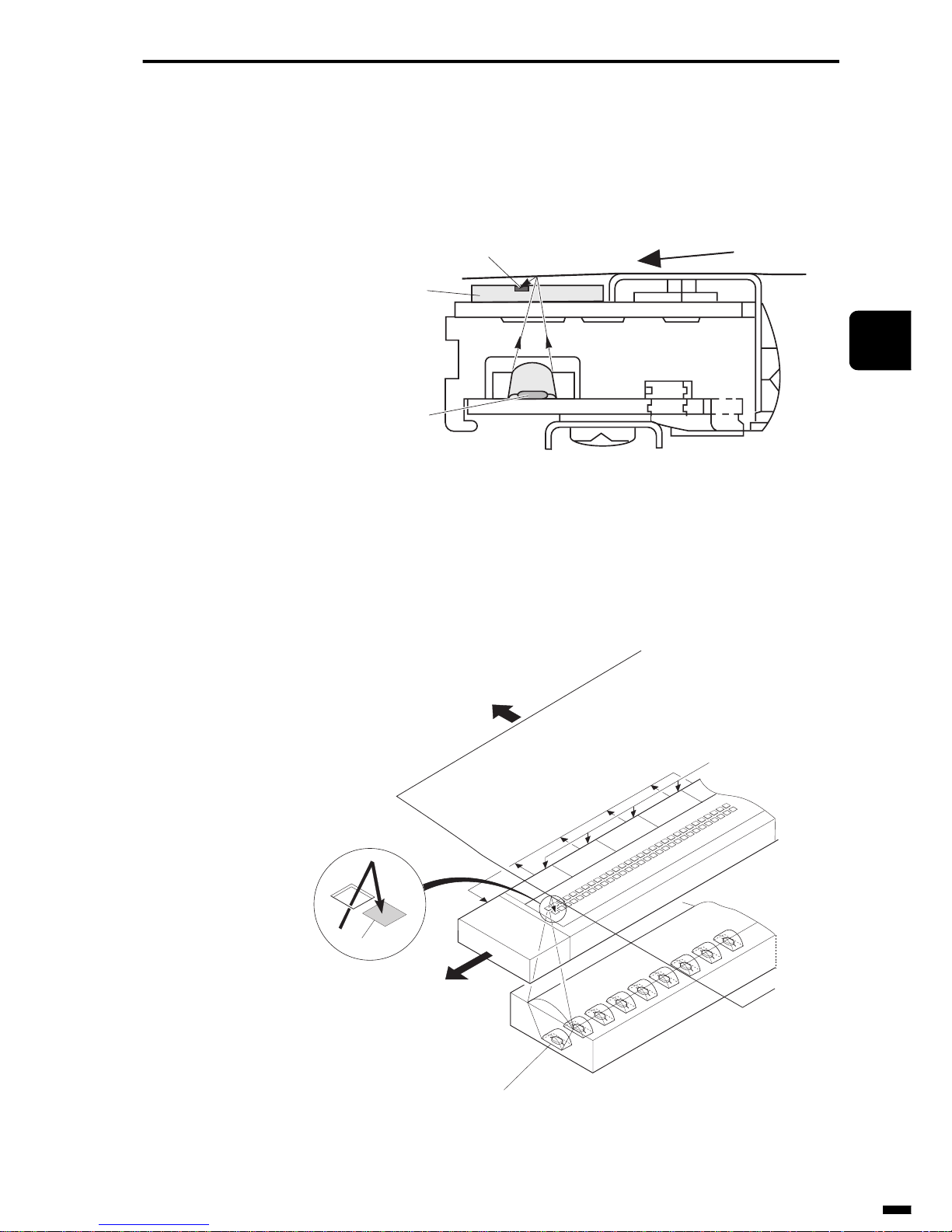
3–13
1
2
3
4
5
6
ït
çi
READING SECTION
3.2.2
α
-Si type
The irradiated light emitted from the LED array is reflected by the document, and is received by the photo-transistor array.
Fig. 3-15 α-Si Type (cross-section view)
The glass substrate has a built-in driv er circuit for amplifying the output of
the received light, and the output of that driver circuit is converted to serial
data to be transmitted to the system controller.
Fig. 3-16 α-Si Type
LED array
Glass substrate
Sensor
Document feed direction
Document
Control
circuit
Sensor
driver4
Analog/serial output
Sensor drive voltage
LED
Sensor
driver3
Sensor
driver2
Sensor
driver1
Document
Sensor
Page 76
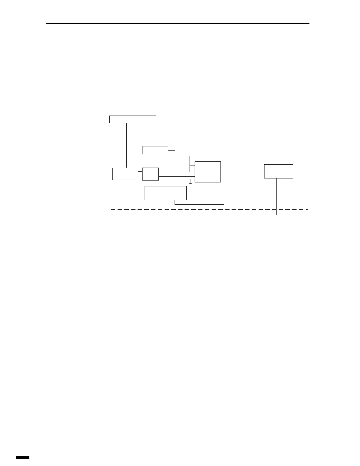
READING SECTION
3–14
4. IMAGE DATA PROCESSOR
After the document is read by the contact sensor, the resulting image data
undergoes various image data processing at the system controller.
The following shows a block diagram outlining the content of image processing.
Fig. 3-17 Block Diagram
4.1 Various Image Data Processing
After the image data has been read, it undergoes various data processing
before it is sent. The following describes these processing types.
• Pre-scan
By the pre-scan, the base color of the white mylar sheet attached to the
document feed section on the contact sensor is read for one line at the start
of document reading so that the unevenness compensation values for the
output contact sensor are stored to shading memory.
• DC generation
DC generation matches the black side reference voltage of the A/D con version circuit with that of the contact sensor.
• AGC circuit
AGC (Auto Gain Control) adjusts for unevenness in the reading system
(LED, white mylar sheet and contact sensor) to prevent the maximum
value exceeding the maximum value of the A/D conversion circuit when
the background color of the white mylar sheet is read for one line.
D/A
conversion
circuit
GENESIS
(UHQ)
Contact sensor
Brightness data
(analog signal)
Image processing section
ABC circuit
A/D
conversion
circuit
Gray scale data
(digital signal)
DC
generation
AGC
circuit
Shading
memory
To coding/decoding
processing section
Binary data
Page 77
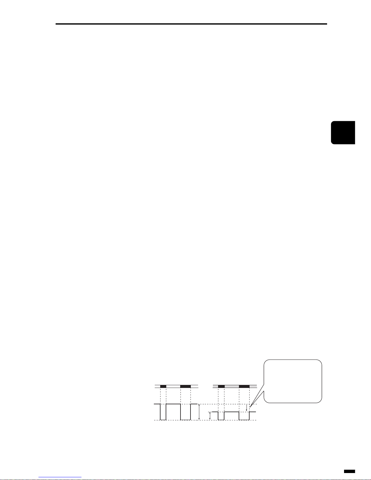
3–15
1
2
3
4
5
6
ït
çi
READING SECTION
• Shading memory
A pre-scan is performed at the start of document reading to store the reading brightness data for the base color of the white mylar sheet to shading
memory. Then, the data stored to shading memory is compared with the
reading brightness data when the document is read to generate uniform
image reading brightness data.
• A/D conversion circuit
This circuit converts the analog signals (voltage signals) that arrive from
the contact sensor to digital image signals.
In the A/D conversion circuit, A/D conversion processing is performed
based upon the reference voltage. As adjusting this reference voltage also
adjusts the reading density range (difference between minimum and maximum output levels) of each pixel, this influences the signal level after A/D
conversion.
• D/A conversion circuit
This circuit converts digital signals for shading compensation data, for
example, into analog signals.
It also generates the white side reference voltage for the A/D conversion
circuit.
• ABC circuit
The ABC (Auto Background Control) function converts the level of the
skin color density in a document so that the reading density of skin color in
a color background document is adjusted as white skin color. This function
is achieved by varying the white reference voltage of the A/D conversion
circuit according to the brightness level of the document to be input.
As shown in Fig. 3-18, the skin color in a document is eliminated by lowering the density range of a color background document to lower than that
of a white background document.
If there were no ABC circuit, color background documents would be read
as black documents.
Fig. 3-18 ABC Circuit Functions
Output level
A
B
The ABC circuit changes
the reference voltage to
lower the FFH (white)
level (to reduce the
reading density range).
<White background
document>
<Color background
document>
Document
surface
FFH (white)
00H (black)
(A): Reading density range of white background document
(B): Reading density range of color background document
FFH (white)
00H (black)
Page 78
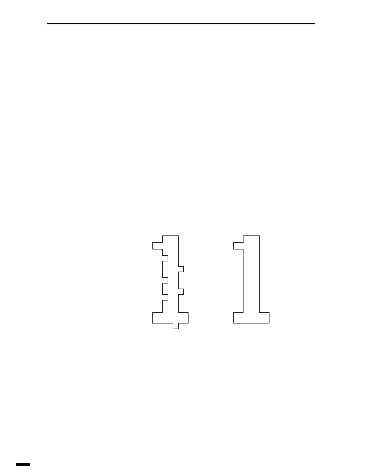
READING SECTION
3–16
• GENESIS (UHQ)
(GEneration of NEw Superior Imaging System (Ultra High Quality))
GENESIS (UHQ) is an image processing method that achieves high-quality images for text documents by performing edge emphasis and notch processing, and high-quality images for documents containing both text and
photos by performing error diffusion processing.
• Edge emphasis
Normally, the contours of the image read by the contact sensor are blurred
or collapsed compared with the contours of the original image. For this
reason, the edge emphasis section compensates for blurring or collapsing
of the contours so that the read image is reproduced more faithfully to the
original image.
• Notch processing
Notch processing is for processing notches in binary data that is processed
by simple binarization. By notch processing, unwanted notches (jagged
sections) are automatically compensated for based upon the information
relating to the focus pixel and peripheral pixels.
Fig. 3-19 Notch Processing
After notch processingBefore notch processing
Page 79

CHAPTER
4
1
2
3
4
5
6
ït
çi
4 RECORDING SECTION
1. INTRODUCTION...................................................................... 4-2
2. IMAGE DATA PROCESSING SECTION ..................................4-3
2.1 Image Area Separation Processing,
Smoothing Processing and Selector............................... 4-4
2.2 Reproduction Ratio Processing Section.......................... 4-8
2.3 Ink Saving/Toner Saving................................................ 4-11
3. PAPER FEED SECTION........................................................ 4-12
3.1 Pickup Section............................................................... 4-12
3.2 Feed/Eject Section........................................................ 4-17
3.3 Detection of Recording Paper Jams.............................. 4-19
4. PRINTING SECTION............................................................. 4-24
4.1 LBP (LASER Beam Printer) ..........................................4-24
4.2 Printing by LASER ........................................................ 4-24
4.3 Flow of Printing ............................................................. 4-26
4.4 Video Control Section/Printer Engine Control Section.. 4-27
4.5 LASER/Scanner Section............................................... 4-32
4.6 Printing Process............................................................ 4-34
4.7 Toner Cartridge ............................................................. 4-46
4.8 BJ (Bubble Jet) Printer.................................................. 4-48
4.9 Printing by Bubbles ....................................................... 4-48
4.10 Printing Section............................................................. 4-50
4.11 Carriage Section ........................................................... 4-51
4.12 Purge Unit ..................................................................... 4-56
4.13 BJ Cartridge.................................................................. 4-58
Page 80

RECORDING SECTION
4–2
1. INTRODUCTION
This chapter describes the recording section on a facsimile.
At the recording section, the image data is processed to data for printing,
and then the recording paper is picked up, printed, and output.
The recording section can be broadly divided into the following three sections:
• Image data processing section
• Paper feed section
• Printing section
This chapter describes each of the components that comprise a recording
section referring to an LBP (LASER Beam Printer) and a BJ printer (Bubble Jet Printer) that are currently the main engines for facsimiles.
Page 81
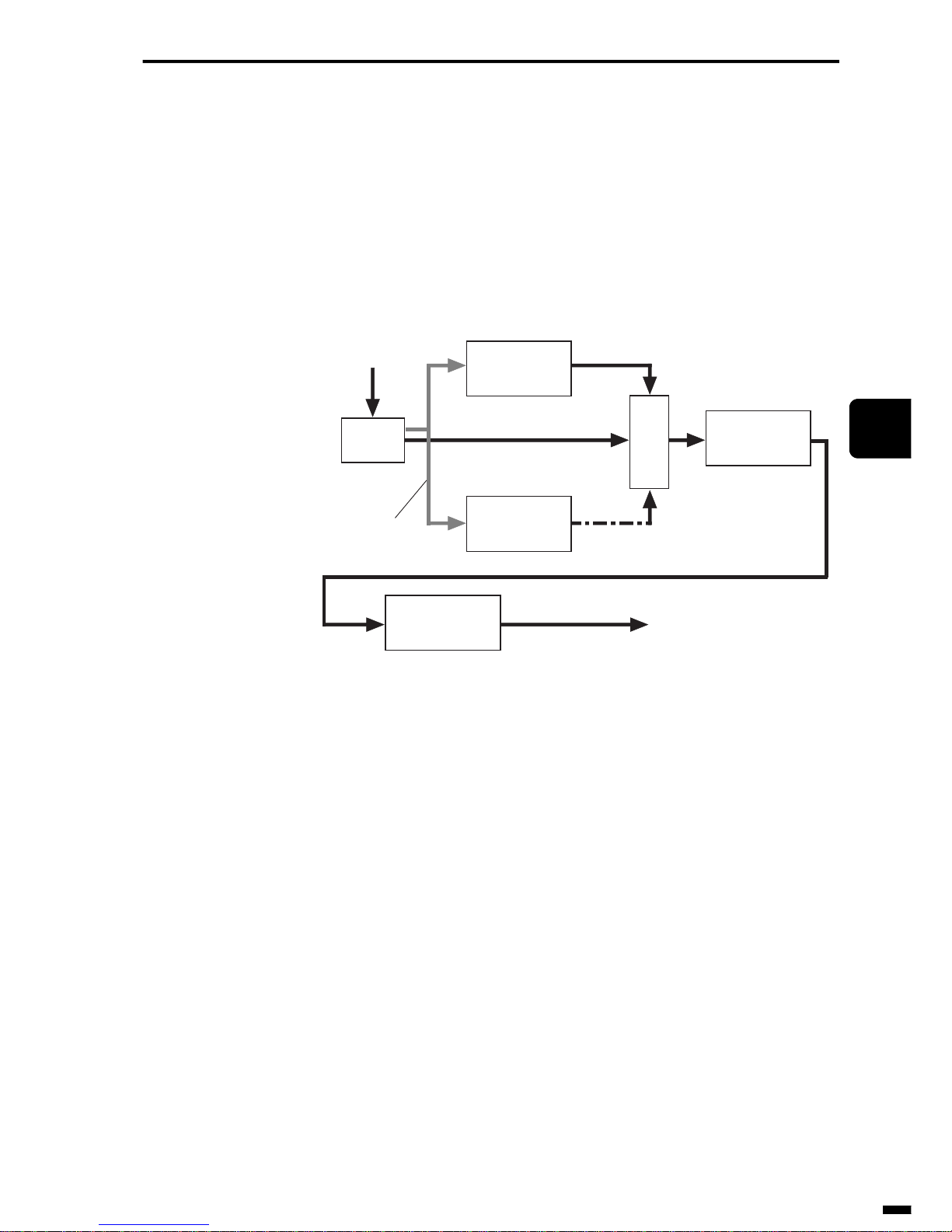
4–3
1
2
3
4
5
6
ït
çi
RECORDING SECTION
2. IMAGE DATA PROCESSING SECTION
The purpose of the image data processing is to achieve better-looking
prints. After the image data has undergone various image processing by
the system control section, it is sent to the printing section. Image data processing is almost the same on both LBP system and BJ system facsimiles.
Fig. 4-1 shows a general flow of image processing.
Fig. 4-1 Flow of Image Processing
First of all, part of the image data is stored in memory. Next, the image
data undergoes smoothing, the process for printing oblique and curved sections of the image data more smoothly . At the same time, in the image area
separation processing, judgment is performed as to whether the image data
is binary data or an image containing half-tones such as a photo. The selector selects whether or not the data is the original data or smoothing data
based upon the judgment results by the image area separation processing.
The image data is then reduced as necessary by the reproduction ratio processing section, and sent to the printing section.
Next, let’s describe of the components in a little more detail.
Memory
Image data input
Smoothing
processing
section
Image area
separation
processing section
Original data
Reproduction
ratio processing
section
Smoothing data
Judgment result
Matrix data
Selector
Image data output
To printing
section
Ink saving
/toner saving
Page 82
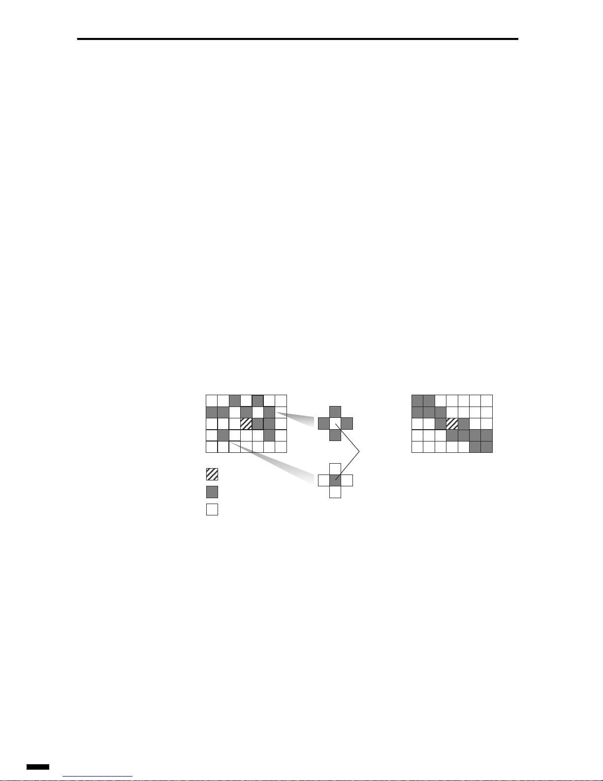
RECORDING SECTION
4–4
2.1 Image Area Separation Processing, Smoothing Processing and Selector
2.1.1 Image area separation processing
Image area separation processing section looks at the pixels around the
pixel (focus pixel) that is to be smoothed, and judges whether the pixels
are part of a binary image or part of an image with half-tones such as a
photo. The following describes “number of isolated pixels” and “number
of black/white reversions” that are used for judgment, and the judgment
criteria.
• Number of isolated pixels
The focus is applied to a certain single pixel, and the total number of isolated pixels in a given matrix centered around that pixel is calculated. For
example, if a certain pixel is white, and the adjacent four pixels are black,
then that pixel is said to be an “isolated pixel.”
Fig. 4-2 Number of Isolated Pixels
In Fig. 4-2 a), the number of isolated pixels is two, and in b) the number of
isolated pixels is zero.
: Focus pixel
: Black pixel
: White pixel
isolated
pixels
a) When there are
isolated pixels
b) When there are
no isolated pixels
Page 83

4–5
1
2
3
4
5
6
ït
çi
RECORDING SECTION
• Number of black/white reversions
The focus is applied to a certain single pixel, and the total number of black/
white reversions in a given matrix centered around that pixel is calculated.
If the adjacent pixels are black and white, then it is said that black/white
reversion is occurring.
Fig. 4-3 Number of Black/White Reversions
In Fig. 4-3, the number of black/white reversions (number of arrows) is 16
when the focus pixel is black.
• Judgment criteria
The image is judged to be a binary image or an image containing halftones when the following condition is satisfied.
Binary image: When the number of isolated pixels is the stipulated number
or less, and the number of black/white reversions is the stipulated number
or less
Image containing half-tones: When the number of isolated pixels is the
stipulated number or more, or the number of black/white reversions is the
stipulated number or more
: Focus pixel
: Black pixel
: White pixel
Page 84
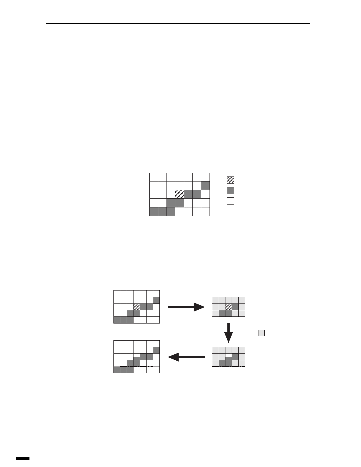
RECORDING SECTION
4–6
2.1.2 Smoothing processing
When image data of a resolution lower than even that of the printer is
printed, the oblique or curved sections of the image become jagged. The
function for removing these jagged parts to smooth oblique or curved sections is called “smoothing.” Smoothing is performed only on binary
images and not on images containing half-tones.
In the following example, let’s describe how smoothing is performed when
image data of a standard resolution is printed on a fine-resolution printer.
The focus is applied to a certain single pixel. When smoothing is performed on that pixel, a pixel pattern enclosed by a dashed line is referenced.
Fig. 4-4 Smoothing (1)
Whether or not the smoothing judgment pattern matches the pixel pattern
enclosed by the dashed line is investigated. If it matches, the focus pixel is
converted according to the smoothing conversion pattern.
Fig. 4-5 Smoothing (2)
: Focus pixel
: Black pixel
: White pixel
: Optionally
pixel
Smoothing judgment
pattern
Before smoothing
Smoothing conversion
pattern
After smoothing
Page 85
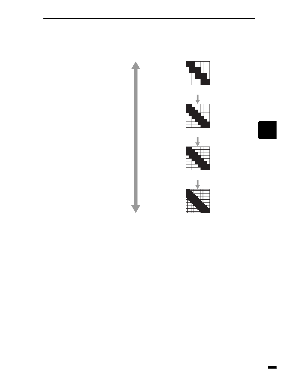
4–7
1
2
3
4
5
6
ït
çi
RECORDING SECTION
Fig. 4-6 shows the result of smoothing when a certain document is printed
in each of the standard, fine, super-fine and ultra-fine modes.
Fig. 4-6 Smoothing (3)
2.1.3 Selector
The selector selects either of the smoothing data or original data based
upon the result of judgment performed by the image area separation processing. If the document is judged to be a binary image, the smoothing
data is sent to the scaling processor, and if the document is judged to be an
image containing half-tones, the original data is sent.
Standard image
Fine converted image
Super-fine converted image
Ultra-fine converted image
High resolution
Low resolution
Page 86

RECORDING SECTION
4–8
2.2 Reproduction Ratio Processing Section
The image is then reduced by one of the Reproduction ratio shown below.
After scaling, the image data is sent to the printing section.
(1) Regular reproduction
(2) Fixed reproduction
The image data is reduced by a reproduction ratio (fixed) that is set on the
user registration switches.
(3) Automatic reproduction
The image data is automatically reduced to fit on a single sheet of recording paper even if the image data is longer than the recording paper.
(4) mm/inch conversion
Normally, the resolution of image data that is received in the G3 mode is
expressed using the millimeter unit system. The resolution of the printer,
however, is expressed using the inch unit system. For this reason, image
data of a resolution expressed in the millimeter unit system is converted to
resolution expressed in the inch unit system held by the printer. This is
called “mm/inch conversion.” mm/inch conversion is performed regardless
of whether or not scaling types (1) to (3) described above are performed.
Next, let’s describe an instance where image data of fine resolution is
printed on a 360 dpi (dots/inch) printer.
• Horizontal scanning direction
First, the mm system units are converted to inch system units. As one inch
is 25.4 mm:
→ 8 (dots/mm) × 25.4 (mm/inch) = 203.2 (dots/inch)
Next, the printer calculates how many dots are used to print a single dot of
the image data.
→ 360 (dots/inch) ÷ 203.2 (dots/inch) = about 1.772
Size of
Image
Data
Size of
Recording
Paper
Reproduction
A3 A4 The image data is reduced by a ratio of 70%.
A3 B4 The image data is reduced by a ratio of 86%.
B4 A4 The image data is reduced by a ratio of 81%.
Page 87
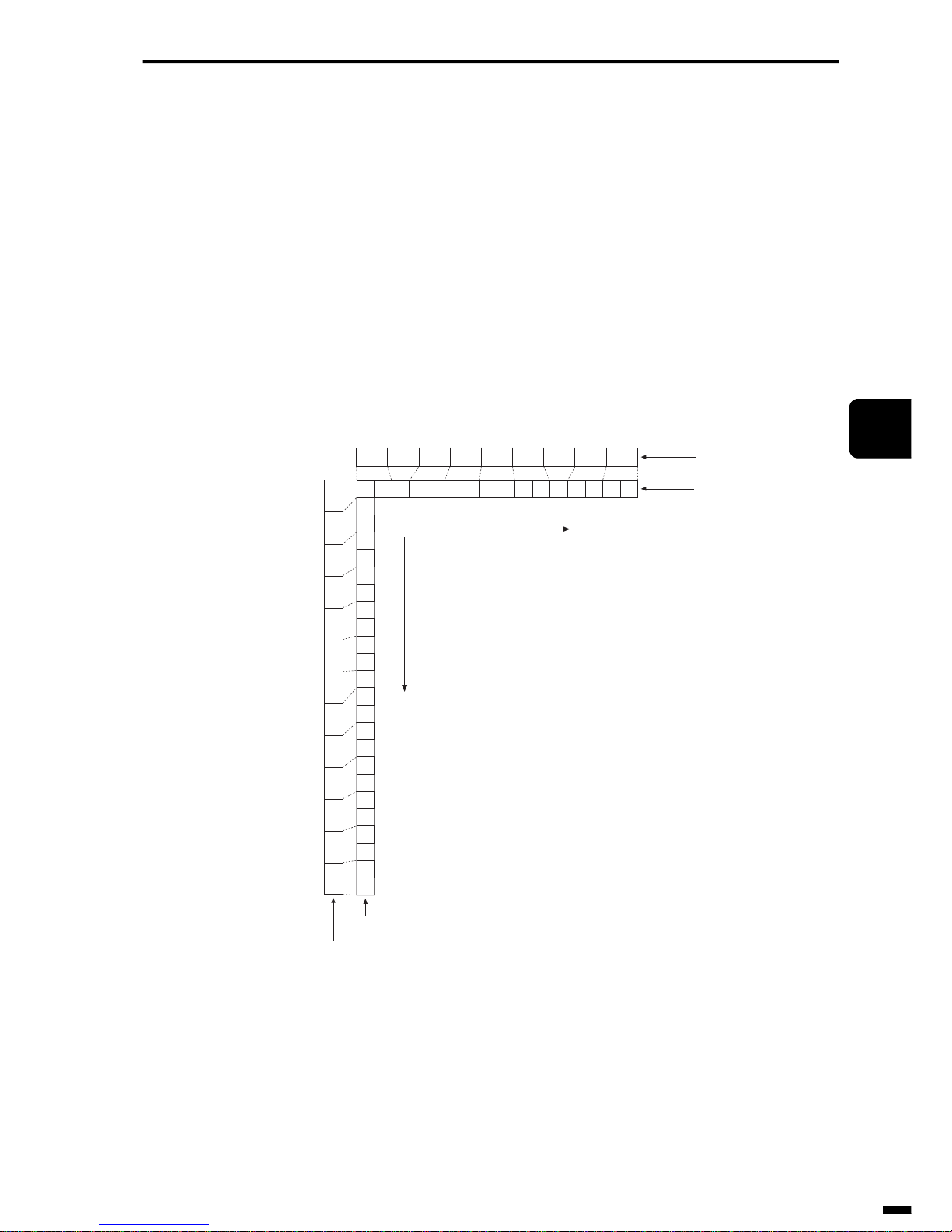
4–9
1
2
3
4
5
6
ït
çi
RECORDING SECTION
As a result, as the printer prints one dot of the image data using 1.772 dots,
this can be converted to the following integer ratio:
→ 1:1.772 = about 9:16
So, the printer knows that nine dots of image data are to be printed using
16 dots.
• Vertical scanning direction
→ 7.7 (dots/mm) × 25.4 (mm/inch) = 195.58 (dots/inch)
→ 360 (dots/inch) ÷ 195.58 (dots/inch) = about 1.847
→ 1:1.847 = about 13:24
Accordingly, the printer prints 13 dots of image data using 24 dots. Fig. 47 shows an example of the dot array in mm/inch conversion.
Fig. 4-7 mm/inch Conversion
When printing is actually performed, density conversion of pixels (horizontal scanning direction) is also performed simultaneously with mm/inch
conversion. This example describes a case where printing is performed on
a BJ printer. The purpose of density conversion is to prevent smudging
when ink adheres to the recording paper and to prevent the printed image
from collapsing. Black pixels are skipped according to the density conver-
1
2
2
3
3
4
4
5
5
6
6
7
8
8
9
9
10
10
11
11
12
12
13
13
123344556678899
1
2
3
4
5
6
7
8
9
10
11
12
13
Horizontal scanning
Vertical scanning
7.7 dots/mm (13 dots)
360dpi (24 dots)
8 dots/mm (9 dots)
360dpi (16 dots)
123456789
Page 88
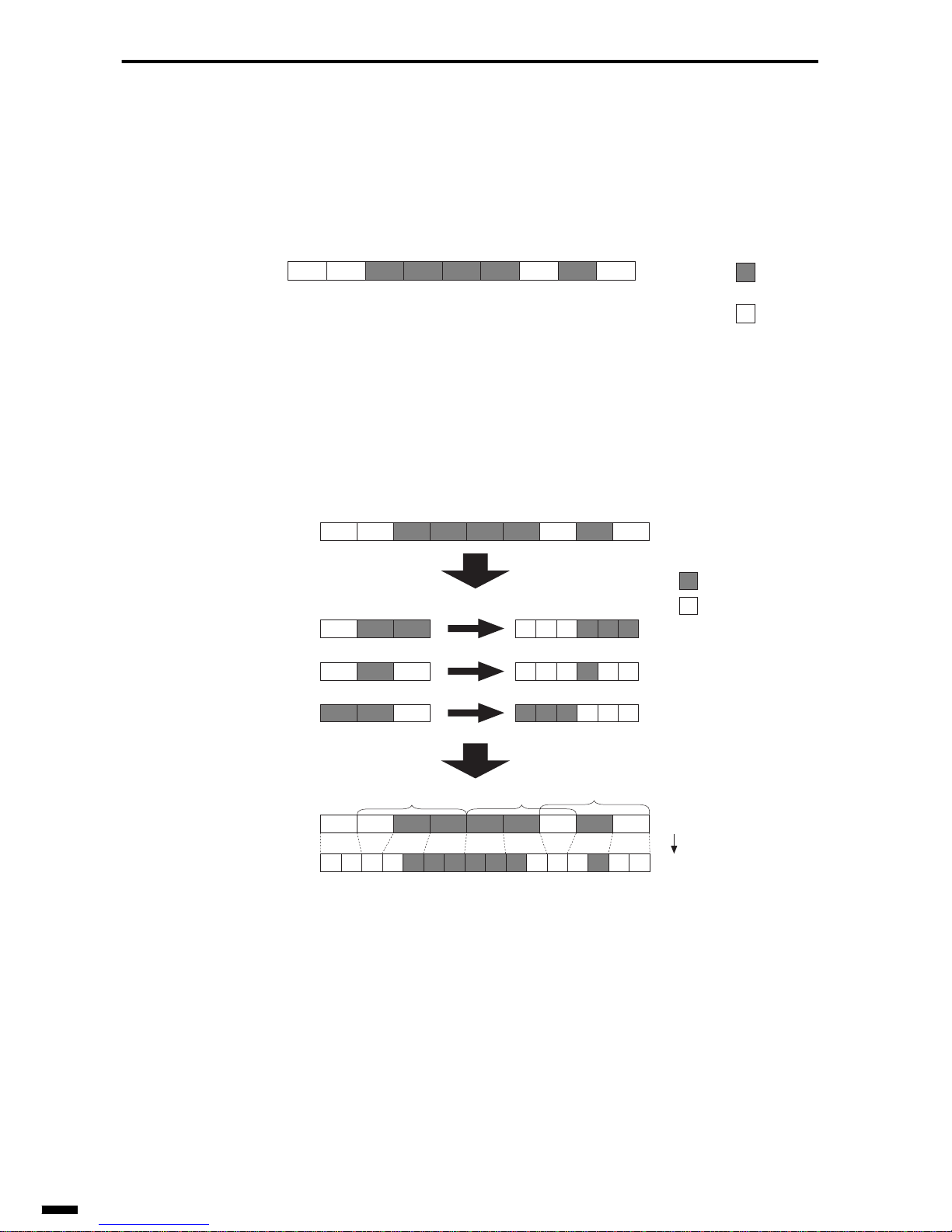
RECORDING SECTION
4–10
sion pattern. (Black pixels are converted to white pixels.) The following
shows an example of this.
There are nine dots of image data of resolution 8 (dots/mm) in the horizontal scanning direction.
Fig. 4-8 mm/inch Conversion and Density Conversion (1)
Such mechanisms as mm/inch conversion and density conversion are performed simultaneously on this image data.
Fig. 4-9 mm/inch Conversion and Density Conversion (2)
: White
pixel
8 dots/mm
123456 897
: Black
pixel
Density conversion pattern
Pattern 1
Pattern 2
Pattern 3
: Black pixel
: White pixel
3456 8
8 dots/mm
123456 897
Pattern 1 Pattern 3 Pattern 2
360 dots/inch
3456 8
12356 91 44 5 6788 9
8 dots/mm
123456 897
3
Page 89
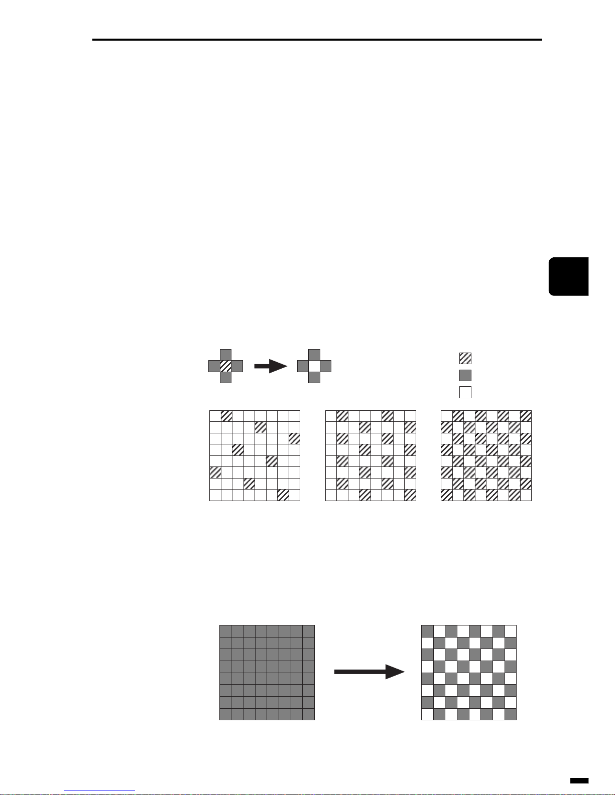
4–11
1
2
3
4
5
6
ït
çi
RECORDING SECTION
2.3 Ink Saving/Toner Saving
This process is performed to save the amount of ink and toner that is consumed during printing. On BJ printers, this is called the “ink saving” function, and on LBP, this is called the “toner saving” function. This function is
valid when it is set on user registration switches. This section describes an
example of the ink saving function.
• Ink saving function
The amount of ink consumed and the ink drying time are reduced by
appropriately converting areas of the image data containing lots of black
pixels to white. To be more precise, the focus is applied to a certain single
pixel, and the pixels to the left, right, top and bottom of that pixel are
investigated. If all of the pixels to the left, right, top and bottom of that
pixel are black, the focus pixel is converted to white. The following three
patterns are available according to the number of pixels to be targeted.
Fig. 4-10 Ink Saving (1)
The following shows an instance where an black/solid image is converted
according to pattern 3.
Fig. 4-11 Ink Saving (2)
: Focus pixel
: Black pixel
: White pixel
Pattern 1 Pattern 2 Pattern 3
Black/solid image Image after conversion
Image is converted
by pattern 3.
Page 90
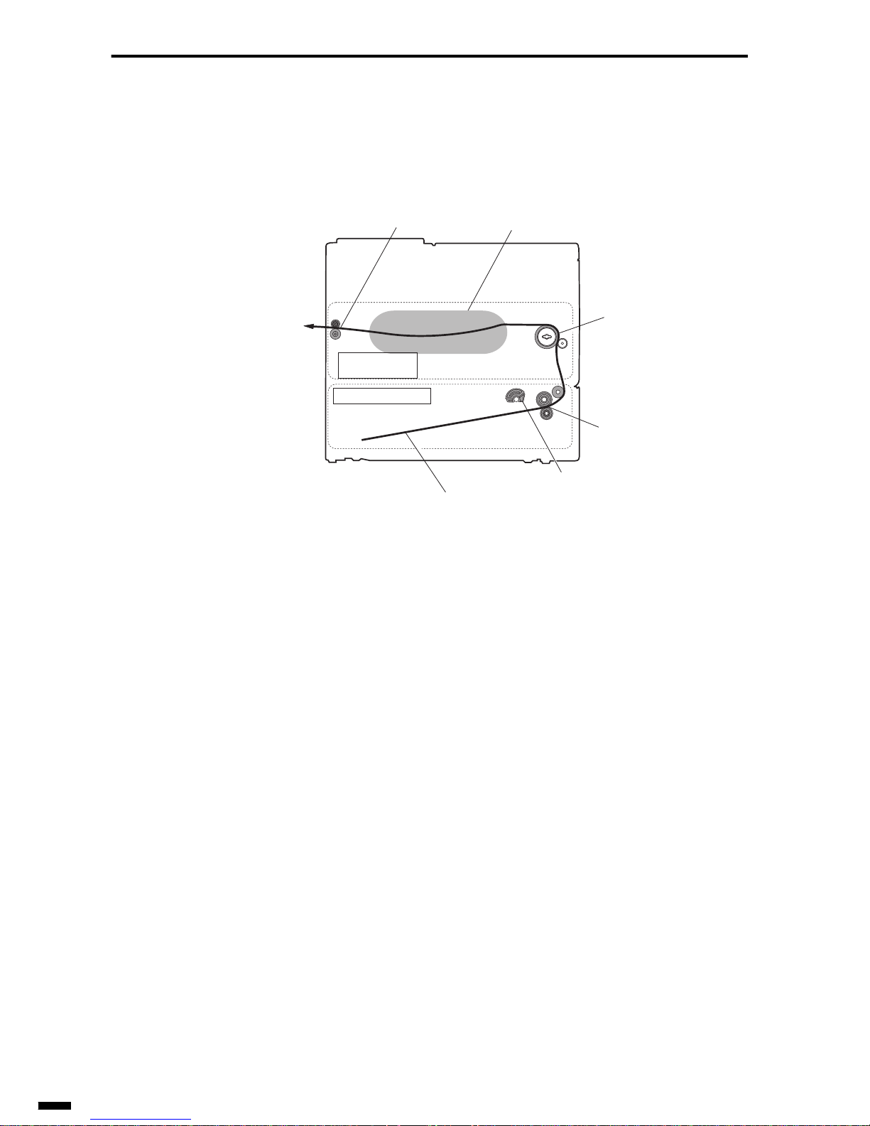
RECORDING SECTION
4–12
3. PAPER FEED SECTION
Fig. 4-12 shows the general path of the recording paper.
Fig. 4-12 Path of Recording Paper
One sheet of recording paper is picked up at a time by the pickup roller and
separation roller, and is sent to the printing section by the feed roller. After
printing has ended at the printing section, the recording paper is output to
the outside of the machine by the eject roller.
Next, let’s describe the pickup section and feed/eject section.
3.1 Pickup Section
The pickup method is broadly divided into two methods, cassette method
and ASF (Auto Sheet Feeder) method. Even in these two pickup methods,
the pickup method is further categorized according to the separation
method of the recording paper.
3.1.1 Cassette method
With this cassette method, the paper cassette filled with recording paper is
attached onto the body of the facsimile. This method allows a relatively
large amount of paper to be picked up. There are three paper separation
methods for this method: claw method, reverse roller method and friction
plate method.
Eject roller
Printing section
Feed roller
Separation roller
Pickup roller
Path of recording paper
Pickup section
Feed/eject
section
Page 91
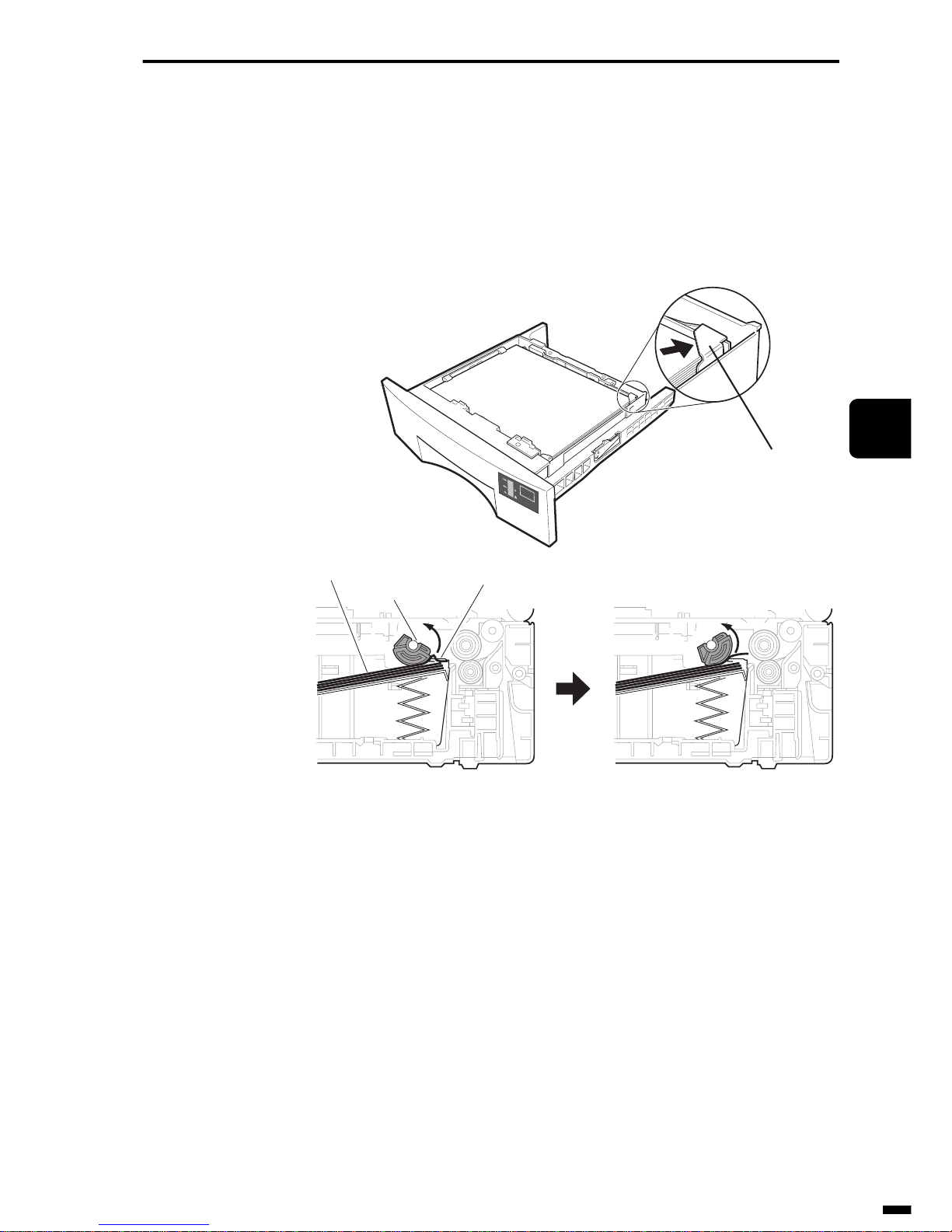
4–13
1
2
3
4
5
6
ït
çi
RECORDING SECTION
(1) Claw method
The claw at the leading edge angled section of the paper cassette holds
down the recording paper. When the recording paper is picked up by the
pickup roller, the retention force of the claw holds down the second sheet
of recording paper onwards and separates only the first sheet of recording
paper.
Fig. 4-13 Claw Separation Method
A
4
Claw
Claw
Recording
paper
Pickup roller
Page 92
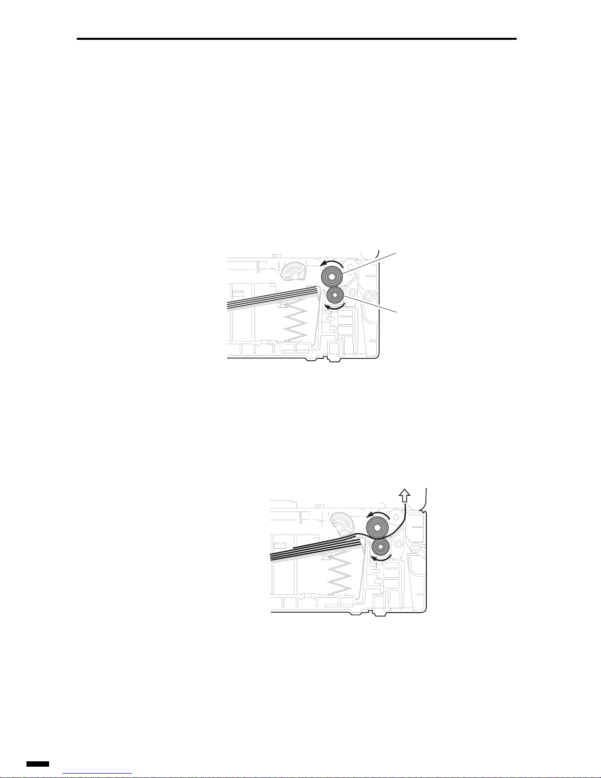
RECORDING SECTION
4–14
(2) Reverse roller method
The recording paper is separated by applying torque in the counterclockwise direction (opposite to the pickup direction) to the reverse roller.
• Operation before paper pickup
Torque in the counterclockwise direction is applied to the separation roller,
or is applied to the reverse roller via a torque limitter. However, as the
torque of the reverse roller is smaller than the torque of the separation
roller, the reverse roller is pulled back to the separation roller to rotate in
the clockwise direction (pickup direction).
Fig. 4-14 Reverse Roller Method 1
• Operation during normal paper pickup
The reverse roller is pulled back onto the recording paper, and rotates in
the clockwise direction (pickup direction).
Fig. 4-15 Reverse Roller Method 2
Separation roller
Reverse roller
Page 93
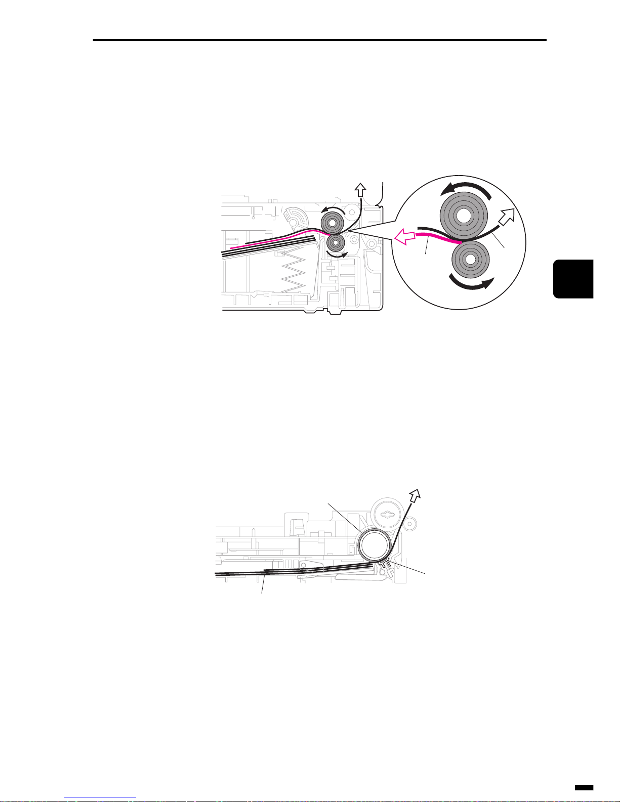
4–15
1
2
3
4
5
6
ït
çi
RECORDING SECTION
• Operation during double-feeding
The reverse roller rotates in the counterclockwise direction, and the
recording paper (second sheet onwards) on the reverse roller side returns in
the counter-pickup direction. Only the recording paper (first sheet) on the
separation roller side is fed to the printing section.
Fig. 4-16 Reverse Roller Method 3
(3) Friction plate method
The friction plate is held against the pickup roller, and the recording paper
is separated by the stopping power caused by friction. The principle of
operation is the same as the Chapter 3, Document Separation Operation on
page 3-6.
Fig. 4-17 Friction Plate Method
1st
sheet
2nd sheet
Friction plate
(separation pad)
Pickup roller
Recording paper
Page 94

RECORDING SECTION
4–16
3.1.2 ASF method
With this method, the recording paper is loaded directly in the pickup
entrance on the facsimile body. Though the number of paper sheets that
can be loaded in one operation is not as much as the cassette method, a feature of this method is that it allows the mechanism to be designed more
compactly . The same conf iguration is also adopted in the sub-pickup methods of units that adopt the cassette method. Claw separation and friction
plate separation methods are available as the separation method used in
ASF methods. The principle of operation is the same as the separation
method in the cassette method.
Fig. 4-18 ASF Paper Feed
Pickup roller
Recording paper
Friction plate (separation pad)
Page 95
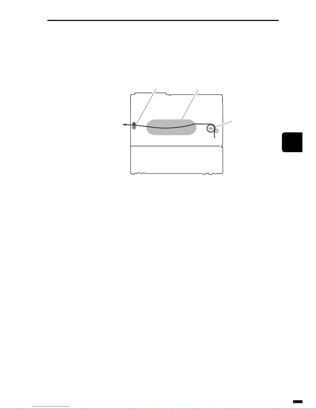
4–17
1
2
3
4
5
6
ït
çi
RECORDING SECTION
3.2 Feed/Eject Section
The recording paper that arrives from the pickup section is sent to the
printing section by the feed roller, and is output to the recording paper output exit by the eject roller after it has been printed.
Fig. 4-19 Paper Feed/Eject Section
Feed roller
Printing section
Eject roller
Page 96
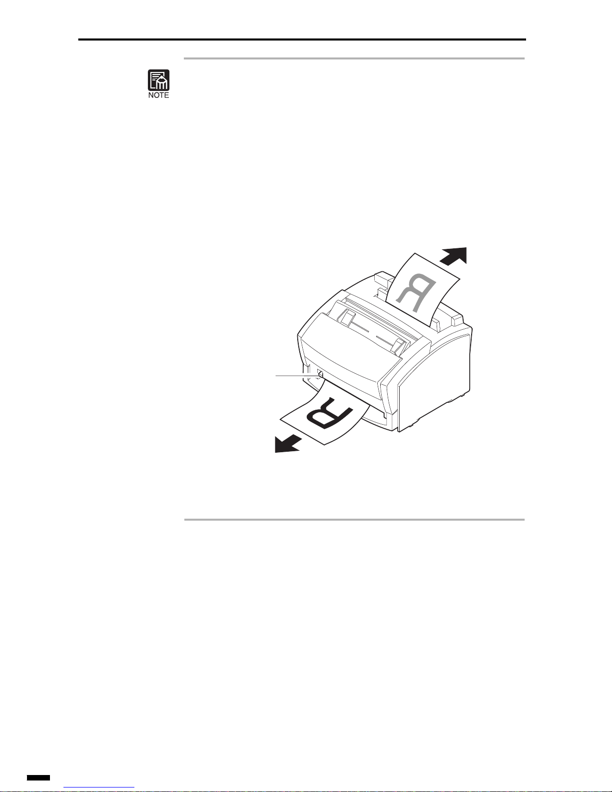
RECORDING SECTION
4–18
Recording Paper Eject Methods
Normally, paper is eject in order from the first sheet after a facsimile is
received. However, on some types of machines, the facsimile is temporarily stored to memory so that it can be output in order from the last page
(print in order). Some types of machines allow the user to select whether to
output the facsimile printed side face down or face up by switching the
paper delivery selector. These types of output are called “face-down paper
delivery” and “face-up paper delivery,” respectively.
Fig. 4-20 Face-up Paper Delivery and Face-down Paper Delivery
Face-up paper delivery
Paper delivery
selector
Face-down paper delivery
Page 97
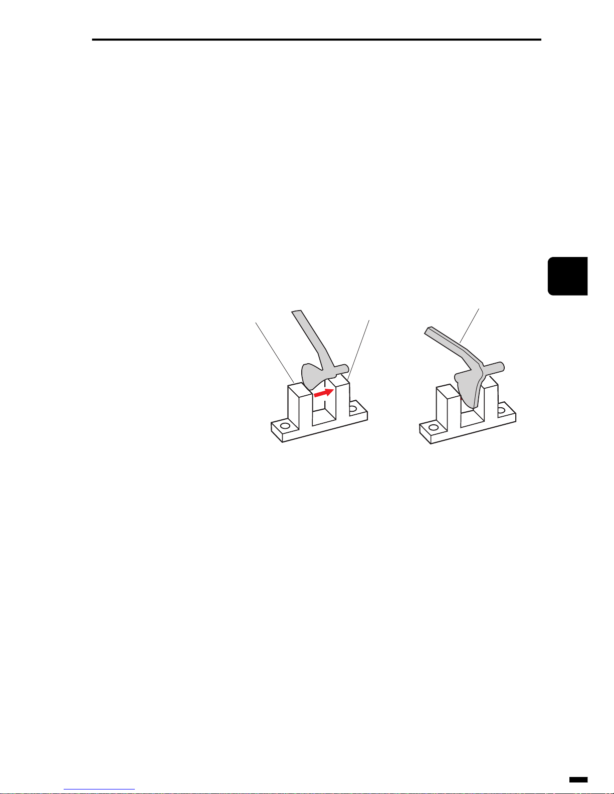
4–19
1
2
3
4
5
6
ït
çi
RECORDING SECTION
3.3 Detection of Recording Paper Jams
A “recording paper jam” is a state where loaded recording paper has
jammed inside the unit without being picked up, fed or ejected. Recording
paper jams are detected by the ON/OFF timing of sensors that detect the
presence of recording paper. Generally, light-transmitting type photo-interrupters which are a kind of optical sensor are used for detecting the presence of recording paper. When the light that is irradiated from the lightemitting section of the photo-interrupter is detected by the light-receiving
section, the sensor turns “ON.” Alternately, when light is blocked by the
actuator and cannot be detected by the light-receiving section, the sensor
turns “OFF.” Changing of the ON/OFF state of the sensor in this way is
used for detecting the presence of recording paper.
Fig. 4-21 Photo-interrupter
Generally, the following four types of recording paper jams occur:
• Pickup jam
• Feed jam
• Fixing unit wrap-around jam (only in case of LBP)
• Eject jam
Light-emitting
section (LED)
Light-receiving section
(photo-transistor)
Actuator
Page 98
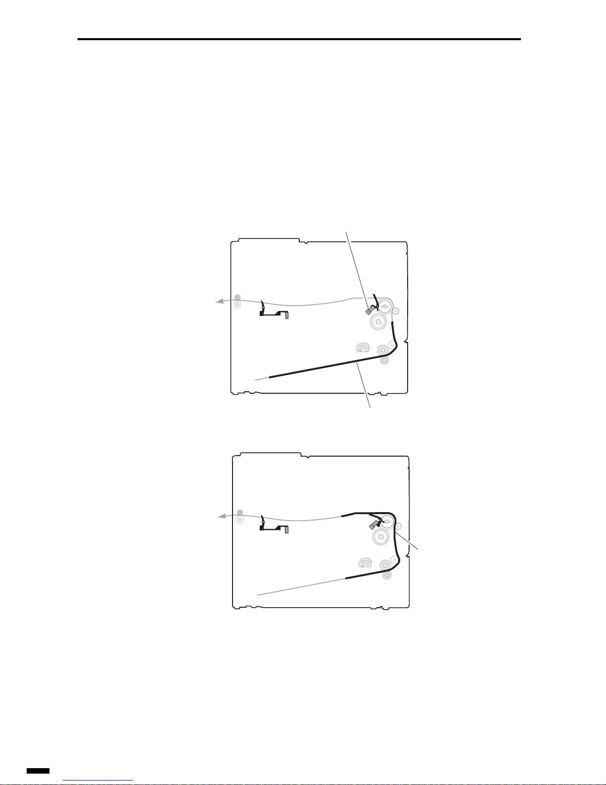
RECORDING SECTION
4–20
• Pickup jam
This jam occurs in the following two instances:
• when the pickup sensor cannot detect the leading edge of the recording
paper within a specified period of time after the pickup operation has
started
• when the sensor cannot detect the trailing edge of the recording paper
within a specified period of time after the sensor has detected the leading edge of the recording paper
Fig. 4-22 Pickup Jam
Recording paper
Pickup sensor
Recording paper
Page 99
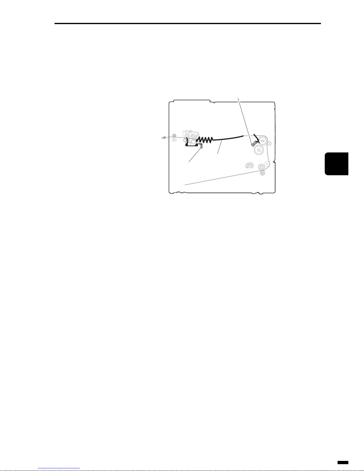
4–21
1
2
3
4
5
6
ït
çi
RECORDING SECTION
• Feed jam
This jam occurs when the eject sensor cannot detect the leading edge of the
recording paper within a specified period of time after the pickup sensor
has detected the trailing edge of the recording paper.
Fig. 4-23 Feed Jam
Pickup sensor
Eject sensor
Recording paper
Page 100
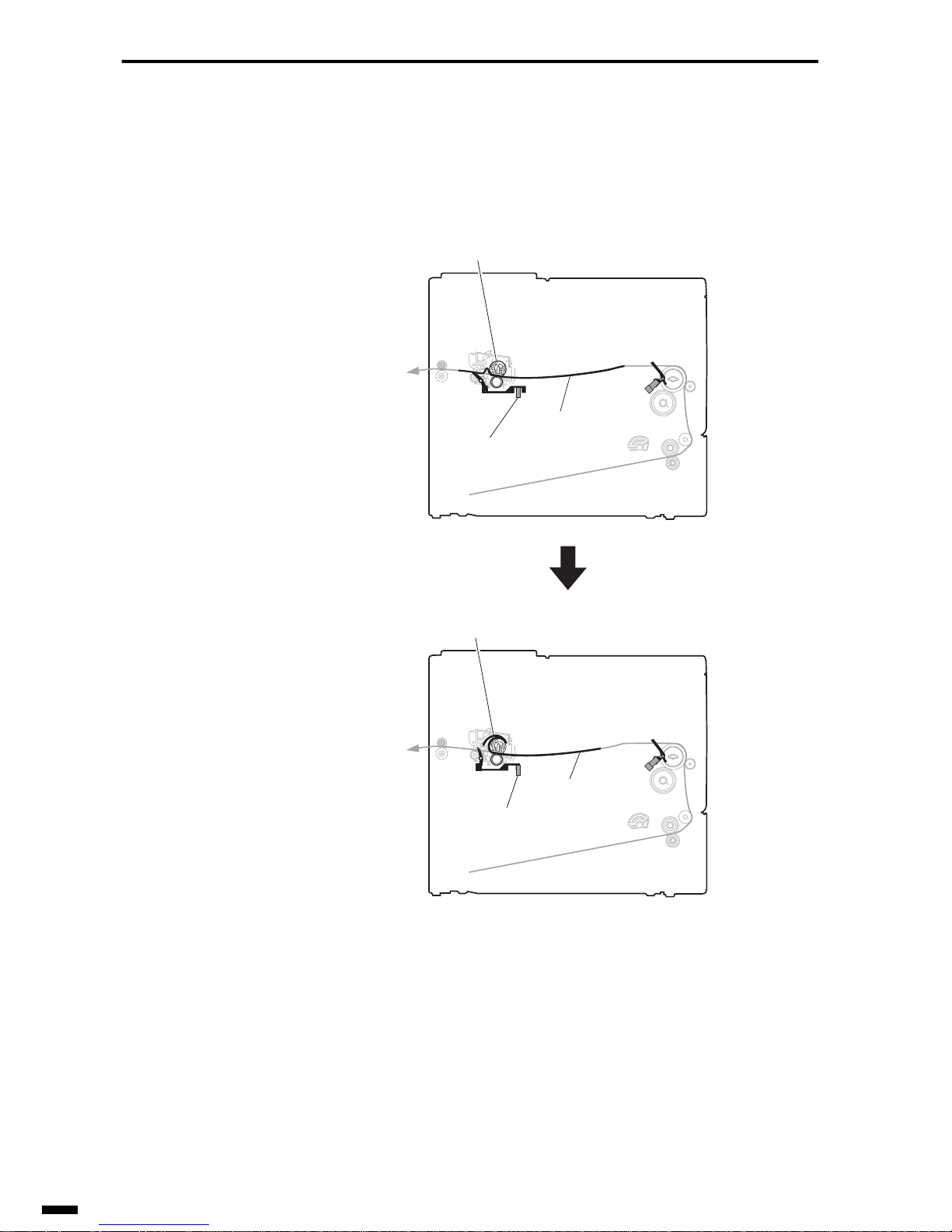
RECORDING SECTION
4–22
• Fixing unit wrap-around jam (only in case of LBP)
This jam occurs when the eject sensor has detected a “no recording paper”
state within a specified period of time after the eject sensor has detected
the leading edge of the recording paper.
Fig. 4-24 Fixing Unit Wrap-around Jam
Fixing roller
Windup onto fixing roller
Eject sensor
Recording paper
Recording paper
Eject sensor detected
no recording paper state.
 Loading...