

Page 1

ENGLISH
Be sure to read this instructions before you use the equipment.
Keep this instructions on hand for reference to ensure optimum preformance.
Page 2

FCC REGULATIONS (For 120V models)
This equipment has been tested and found to comply with the limits for a Class A digital device, pursuant
to Part 15 of the FCC Rules. These limits are designed to provide reasonable protection against harmful
interference when the equipment is operated in a commercial environment. This equipment generates,
uses, and can radiate radio frequency energy, and if not installed and used in accordance with the
instruction manual, may cause harmful interference to radio communications. Operation of this equipment in a residential area is likely to cause harmful interference in which case the user will be required to
correct the interference at his own expense.
Do not make any changes or modifications to the equipment unless otherwise specified in the manual. If
such changes or modifications should be made, you could be required to stop operation of the equipment.
RADIO INTERFERENCE REGULATIONS (For 120V models)
This digital apparatus does not exceed the Class A limits for radio noise emissions from digital apparatus
set out in the Interference-causing equipment standard entitled "Digital Apparatus", ICES-003 of the
Industry Canada.
RÈGLEMENT SUR LE BROUILLAGE RADIOÉLECTRIQUE (For 120V models)
Cet appareil numérique respecte les limites de bruits radioélectriques applicables aux appareils
numériques de Classe A prescrites dans la norme sur le matériel brouilleur: "Appareils Numériques",
NMB-003 édictée par l'lndustrie Canada.
Für EMVG
Dieses Produkt ist Gebrauch im Wohnbereuch, Geschäfts-und Gewerbebereich sowie in kleinbetrieben
vorgesehen.
Copyright
Copyright © 1998 by CANON ELECTRONICS INC. All rights reserved. No part of this publication may
be reproduced, transmitted, transcribed, stored in a retrieval system, or translated into any language or
computer language in any form or by any means, electronic, mechanical, magnetic, optical, chemical,
manual, or otherwise, without the prior written permission of CANON ELECTRONICS INC.
Trademarks
Canon Electronics is a registered trademark of Canon Electronics Inc.
Kodak is a trademark of Eastman Kodak Company.
3M is a trademark of Minnesota Mining Manufacturing Company.
TUSCAN is a trademark of the TUSCAN Corporation.
Other brand and product names may be trademarks or registered trademarks of their respective companies.
Page 3

Contents
BEFORE YOU BEGIN ... 1
Important features .......................................................................................................... 1
Conventions ................................................................................................................... 2
Work safely!............................................................................................................. 3
■ Choosing a safe location...................................................................................... 3
■ Selecting a power source..................................................................................... 5
Important warnings .................................................................................................. 6
Unpacking: What's in the box?....................................................................................... 7
Important parts and their functions................................................................................. 7
Preparing the printer ..................................................................................................... 8
Preparing the carrier ..................................................................................................... 9
Preparing the lens ........................................................................................................ 10
■ Fixed lens........................................................................................................... 10
■ Zoom lenses ...................................................................................................... 10
■ Switching the lens .............................................................................................. 10
The operation panel keys............................................................................................. 12
OPERATING PROCEDURES 14
Turning the unit on/off .................................................................................................. 14
Setting the film ............................................................................................................. 14
Adjusting the image...................................................................................................... 15
■ Rotating the image ............................................................................................. 15
■ Enlarging and reducing image size .................................................................... 15
■ Focusing the image............................................................................................ 15
Printing ......................................................................................................................... 16
■ Starting a print.................................................................................................... 16
Automatic adjustment ........................................................................................ 17
Manual adjustment............................................................................................. 17
If you use Fileprint 250, please select paper size set on the Paper Tray .......... 17
If you use Fileprint 400, please select paper Cassette you want to use ............ 17
■ Setting automatic border removal ...................................................................... 19
■ Using trimming ................................................................................................... 20
What is trimming? .............................................................................................. 20
Defining an area for trimming............................................................................. 20
Setting an area with the area setting tapes (option) .......................................... 21
MAINTENANCE AND TROUBLESHOOTING 22
Changing the lamp ....................................................................................................... 22
Routine cleaning .......................................................................................................... 24
■ Cleaning the screen and main unit .................................................................... 24
■ Cleaning the lens ...............................................................................................24
Troubleshooting ........................................................................................................... 25
User Call Errors............................................................................................................ 26
Service Call Errors ....................................................................................................... 27
SPECIFICATIONS 28
Page 4

Page 5

BEFORE YOU BEGIN ...
BEFORE YOU BEGIN ...
These instructions describe the operating procedures for the Canon
Microfilm Scanner 400. After you set up the unit, keep this manual
in a convenient location so you can find it when you need it.
Important features
❏ Saves space
The economical design of this compact film scanner requires less
space on your desk or work table.
❏ Automatic film detection
The unit automatically detects the presence of negative film or
positive film and performs accordingly. Troublesome adjustments
for the type of film are not required.
❏ Uses a variety of film formats
A wide variety of roll/fiche carriers or auto carriers can be installed so you can use several film formats like microfiche, aperture card, and roll film.
❏ Easy operation
Operations like border removal and image trimming can be performed at the press of a few keys before printing.
❏ Easy expansion
With the installation of an SCSI board (sold separately), you can
connect the unit to a personal computer for advanced operations
like CAR detection and image transfers.
1
Page 6

BEFORE YOU BEGIN ...
Conventions
A few symbols and notations alert you to additional information
that will make operation of the scanner more efficient, trouble
free, and safe.
(➞13)
A number preceded by an arrow and enclosed in parentheses shows
you the page number that contains more information about the
previous statement or paragraph.
Notes provide additional hints or advice about making the
operation easier or saving time.
Caution notices alert you to incorrect procedures that may
damage the equipment.
WARNINGS ARE FOR YOUR SAFETY. FAILURE TO FOLLOW WARNING INSTRUCTIONS CAN CAUSE SERIOUS
INJURY TO YOU OR YOUR CO-WORKERS.
2
Page 7

10cm
Work safely!
Work safely!
To ensure safe, efficient operation, read the follow precautions
and recommendations before you choose a location and set up the
system.
Choosing a safe location
■ To ensure adequate space for ventilation, operation, and mainte-
nance, make sure there is enough space around the system on all
sides. To prevent overheating, never block the ventilation slots.
10cm
50cm
■ Avoid exposure to direct sunlight. When exposure to sunlight is
unavoidable, install curtains to protect the unit.
■ Avoid a dusty location. Dust can adversely affect the internal parts
of the unit.
■ Do not set up and use the unit in a location where the unit is ex-
posed to water, steam, or high humidity. Keep all liquids away
from the unit.
■ Avoid areas like laboratories where fumes from ammonia, acetone,
or other volatile chemicals are present. Never use any kind of
volatile, flammable spray near the unit.
3
Page 8

Work safely!
■ Never set up the unit in an area where flammable substances like
alcohol, thinner, or other organic chemicals are present.
■ Select a flat, stable surface that can support the 26 kg (57.2 lb)
weight of the unit.
■ Choose a location that is free of excessive vibration.
■ Avoid a location subject to sudden or wide changes in tempera-
ture. Condensation inside the unit can cause poor print quality.
Use the unit in a location within these ranges for temperature and
humidity.
Temperature 10˚C to 32.5˚C (50˚F to 90.5˚F)
Humidity 10% to 85% RH
■ Do not place the unit near large speakers, a radio, a television, or
any other type of equipment that can generate a strong magnetic
field.
4
Page 9

Selecting a power source
Power supply requirements
Work safely!
U.S.A. 120V, 50-60 Hz
Europe 220-240V, 50-60 Hz
(other areas)
If you have any questions about the power source at
your work site, contact your supplier or the power company.
■ The unit should have an independent power source that is not
shared with any other electrical device. If you have to use an extension cord or power strip, make sure the total ampere rating for
all the equipment does not exceed the ampere rating of the extension cord.
■ Do not place anything on the power cord, and do not locate the
unit where people working around the unit will walk on the cord.
With no variation
more than 10%
above the rated
power on the unit
label.
■ Do not bundle the power cord or wrap it around an object like a
table or chair leg. The area around the unit should be clear of all
obstacles. In case of an emergency, you should be able to reach
the power source quickly to unplug the cord.
■ To remove the power cord from the power outlet, grasp the head
of the plug firmly to remove it. Never pull on the cord to remove
the plug from the power outlet. Never touch the power cord with
wet hands.
5
Page 10

Work safely!
Important warnings
Before you use the equipment, make sure you and your co-workers read the following warnings about using this equipment.
PAY ATTENTION TO THESE WARNINGS! FAILURE
TO FOLLOW THESE WARNINGS COULD RESULT
IN INJURY FROM FIRE OR ELECTRICAL SHOCK!
■ Use only the power cord supplied with the unit.
■ Never disassemble the unit. There are no user servicable parts
inside the unit.
■ If you detect strange noises, odors, or smoke around the unit, turn
the power switch off immediately, remove the plug from the power
source and call for service.
■ Handle the unit carefully to avoid dropping it, hitting it, or sub-
jecting it to strong shock or vibration. If something collides with
the unit or hits it, turn it off immediately, remove the plug from
the power source, and call for service.
■ Before you move the unit even a short distance, turn off the power
switch and remove the plug from the power source.
■ Never place anything on top of the unit, especially a liquid con-
tainer like a flower vase.
■ When you are working around the unit, avoid wearing loose fit-
ting jewelry like bracelets and necklaces.
■ Keep the work area clear of metal clips, pins, paper clips and other
types of fasteners. If something falls into the unit accidentally,
turn the unit power switch off, unplug the power cord from the
power source, and call for service.
■ To avoid possible injury from falling objects, never place heavy
objects on the unit.
■ If the unit is not to be used for a long period, turn the power switch
off and unplug the power cord from the power source.
■ Avoid touching internal parts when you perform routine cleaning
or maintenance like changing the lamp. Some parts inside the main
unit generate high temperatures and high voltages.
■ To avoid minor injuries, avoid touching the metal studs on the
bottom of the unit when you move it.
6
Page 11

Work safely!
Unpacking: What's in the box?
When you unpack the box, use the checklist below to make sure
that you have everything. If anything is missing, contact your supplier.
■ Microfilm Scanner 400
■ Halogen lamp
■ Power cord
■ Lens label
■ Instructions
■ Warranty Card (U.S.A. and Canada only)
Important parts and their functions
Before you use the unit, take a few minutes to become familiar
with the names of the important parts.
Screen
Displays images and allows you to view
images before you print them.
Operation panel
Provides keys that allow you to perform
settings for image adjustment or film
mode selection.
DIN connector
Allows you to connect a
cable for the Autocarrier
100C, 100R, 100M, FS
Controller I or Roll/Fiche
carrier 200.
Power switch
Allows you to turn power on and
off.
Light adjustment dial
Allows you to adjust the intensity of the light.
Adjust to the magnification power of the interchangeable lens.
Area setting cursor (option)
Allows you to define and trim
an area for printing if you do
not want to print the entire image.
Lens holder
Holds an interchangeable
lens
Carrier stage
Holds an interchangeable
carrier.
Lamp unit
Holds the lamp for the main source of
illumination. Remove to change the
halogen lamp.
Film control knob (option)
Allows you to transport film on the carrier you
have installed. Turn the knob right to advance
the film and turn it left to reverse wind the film.
(This is not possible with the FS Controller I or
III.)
7
Page 12
Work safely!
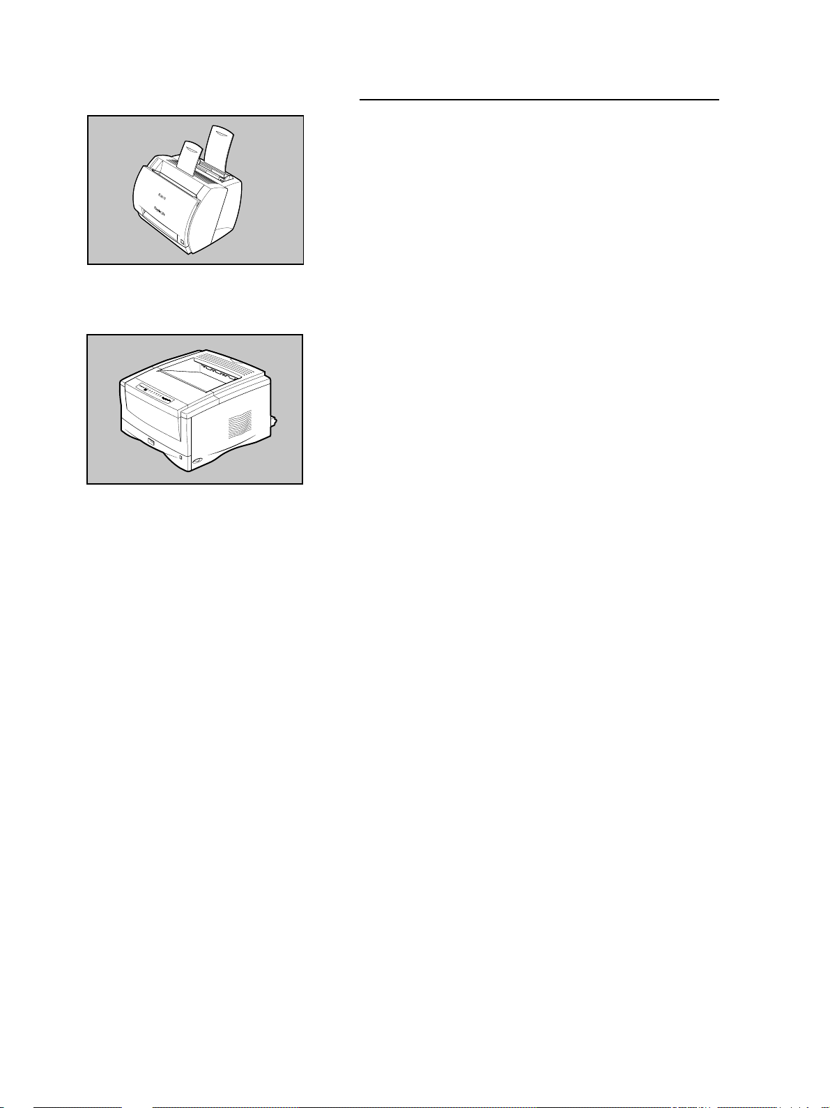
Canon Fileprint 250
Preparing the printer
In order to print images, you need to connect the Canon Fileprint
250 or Canon Fileprint 400 (sold separately). For details about
connection and other important operations for the printer, call for
service from your supplier or see the instructions you received
with the printer.
Canon Fileprint 400
8
Page 13

Work safely!
Preparing the carrier
This is a list of the all the carriers that can be installed and used
with the Microfilm Scanner 400. For more details about these
options, contact your supplier. For details about installation and
operation, refer to the instructions provided with each auto carrier.
■ Fiche Carrier 190RII
A film carrier which allows viewing of fiche, jackets, or aperture
cards up to 105 mm x 190 mm.
■ Autocarrier 100C (AC100C)
A motorized auto carrier for 16 mm cartridge film cartridges
(ANSI, ANSI ENCLOSED*1, Kodak Ektamate, 3M) that features
fast autoloading and high speed film feeding for image display.
■ Autocarrier 100M (AC100M)
A motorized auto carrier for 3M or TUSCAN M-Type*2 cartridges
that feature fast autoloading and high speed film feeding for image display.
■ Autocarrier 100R (AC100R)
A motorized auto carrier for 16 mm or 35 mm film wound on
standard open reels.
■ FS Controller I
A motorized auto carrier for 16 mm cartridge films (ANSI, Kodak
Ektamate, 3M). This carrier is required for reading film marked
with blips for image search and retrieval.
■ FS Controller III
A motorized auto carrier for the new 16 mm cartridge films (ANSI,
Kodak Ektamate, 3M). This carrier is required for reading film
marked with blips for image search and retrieval.
■ Roll/Fiche Carrier 200
A motorized fiche auto carrier for either fiche, jacket, or aperture
card format film, 16mm/35mm film standard open reels or 3M,
TUSCAN M-Type*2 cartridges.
*1 ANSI ENCLOSED cartridge is defined as ANSI MS-15.
2
*
TUSCAN M-Type is a TUSCAN cartridge with a 3M-type core.
9
Page 14
Work safely!
Preparing the lens
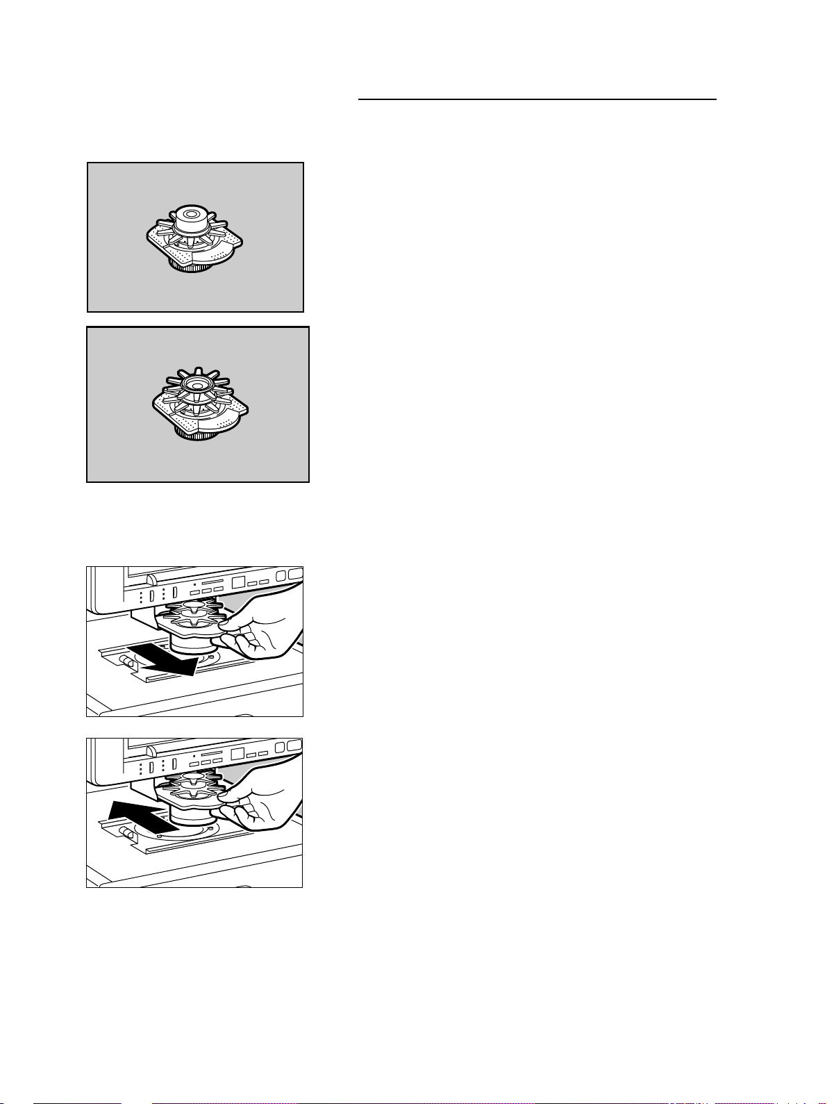
The following types of lenses are available.
Fixed lens
EX7 (x7)
Zoom lenses
EZ01 (x9.5 to x16)
EZ02 (x16 to x32)
EZ03 (x30 to x55)
EZ04 (x10 to x24)
Switching the lens
Follow the procedure below to install or exchange lenses.
1. If a lens is already installed, grasp the edge of the holder and slide
it out of the unit.
2. Slide the other lens into the unit.
10
Page 15
Work safely!
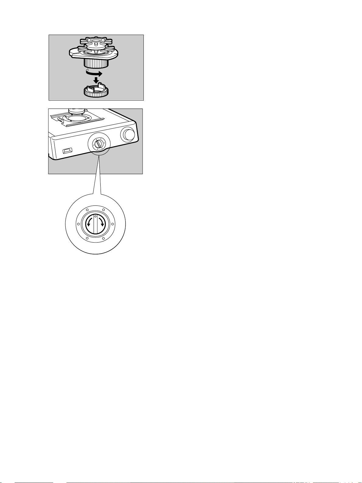
If you are using the FS Controller I, before you insert the lens,
remove the bottom cover of the lens as shown in the illustration.
Make sure you keep the cover and install it on the lens again after
it is removed from the unit.
3. Turn the light adjustment dial to the left or right to adjust the light
intensity of the screen. Adjust the light intensity to the type of
lens installed.
To adjust the light intensity for the lens installed, adjust the light
intensity to the color label for the lens shown on the lens label.
f
a
e
d
Light adjustment dial
c
b
Lens Label
11
Page 16
Work safely!
12 45 67 89
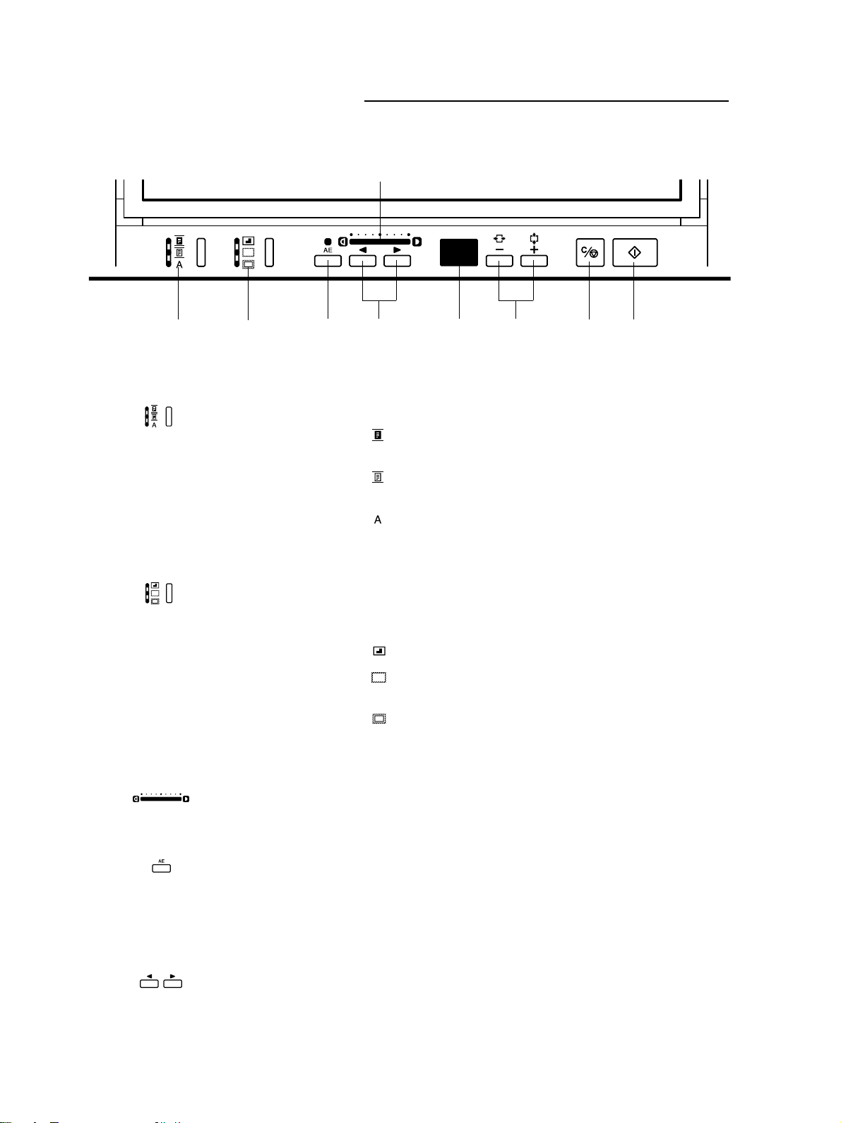
1 Negative/Positive key
The operation panel keys
3
Three settings are available:
( ) In negative film mode, produces positive prints from nega-
tive film images.
2 Border key
3 Print Density display
4 AE On/Off key
( ) In positive film mode, produces positive prints from posi-
tive images.
( ) In automatic mode, selects the mode based on the type of
film detected.
Allows you to remove the dark background or trim the area of the
image that you want to print.
Three settings are available:
( ) Frames an area.
( ) Automatically removes the black border around the image
for printing.
( ) Automatically removes most of the black border around
the image but leaves a border up to 5 mm around the image.
Displays the selected print density. Also displays the sharpness
and date messages when you set these features.
Turns automatic print density selection on and off.
If the FilePrint 400 is connected, Hold down the [AE] key for
about 5seconds to start the cleaning mode. “A4” is shown in the
page count display.
5 Print Density Adjustment key
Press to select print density automatically.
12
Page 17

6 Print/Error Display
7 Print Number Setting key
Work safely!
Displays the number of prints (01 to 99). Also displays User Calls
and Service Calls.
User Calls
Warn you of problems that require your immediate attention. A
user call is a 2-digit code consisting of a letter and a number. User
Call L4 for example means the printer door is open. (➞26)
Service Calls
Warn you of problems that require the service of a qualified technician. Service calls are 4-digit codes consisting of the letter E
and number and then two numbers shown alternately in the display. If you see E2 and 03 displayed alternately, this means Ser-
vice Call E203. (➞27)
Use these keys to set the number of copies to be printed. Press
the plus (+) key to increase the number and the minus (-) key to
decrease the number.
You can also use these keys to select the cassette if you are specifying the area and the FilePrint 400 is connected.
If the FilePrint 400 is connected and when in the cleaning mode,
use the Plus (+) or minus (-) key to set the size of the cleaning
paper (A4 or Letter).
8 Clear/Stop key
9 Print Start key
Press this button to cancel printing or change the number of
copies to be printed. If the FilePrint 250 is connected, you can
also use this button to switch to paper size setting mode.
If the FilePrint 400 is connected, you can also use this button to
switch to cassette selection mode.
Press this button to print.
13
Page 18
OPERATING PROCEDURES
OPERATING PROCEDURES
This section describes procedures for normal operation of the unit:
■ Turning the unit on and off.
■ Adjusting the image on the screen.
■ Printing the image on the screen.
Turning the unit on/off
Follow the procedure below to turn the unit on and off.
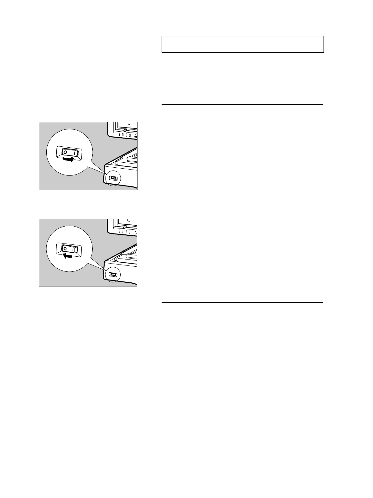
1. If you have installed an FS Controller III auto carrier, turn the
controller on first.
2. On the front of the main unit, locate the power switch on the lower
left corner then press the I side of the switch to turn the power on.
3. Turn on the power switch of the printer.
After you turn the unit on, the Print display starts to blink and will
continue to blink while the unit warms up. While the Print display
is blinking, you cannot start operation. When the Print display
stops blinking and stays on, the unit is ready for normal operation.
4. To turn the unit off, press the O side of the power switch.
Setting the film
Load the auto carrier with the film you want to view. For details
about the auto carrier installation, see the instructions you received
with the auto carrier.
14
Page 19
OPERATING PROCEDURES
Adjusting the image
Follow the procedure below to adjust the image on the screen.
Read and perform this procedure correctly to attain a crisp image
on the screen and a clear printed copy.
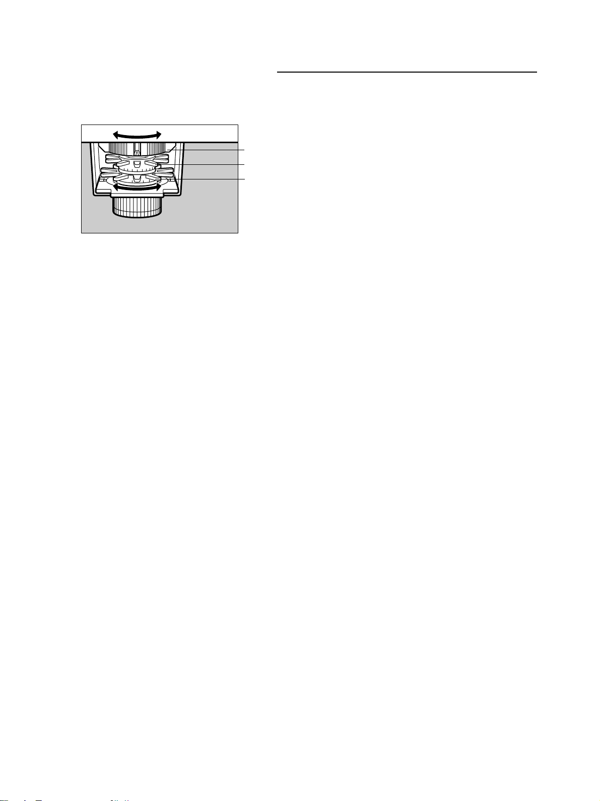
Rotating the image
1
2
3
To rotate the image to the desired angle, rotate the rotation fin 1
to the left or right.
Enlarging and reducing image size
To make the image larger or smaller, rotate the zooming fin 2 on
the lens to the left or right.
Focusing the image
To focus the image on the screen, rotate the focusing fin 3 on the
lens to the left or right.
15
Page 20
OPERATING PROCEDURES
Printing
The image on the screen can be printed with a printer connected
to the unit. This section describes how to set the film mode and
execute a print.
Starting a print
1. Check the main unit and the printer and make sure that they are
both turned on. (The power switches should be set to the I position.)
You can execute a print after both the main unit and printer have
warmed up. The main unit is warmed up when the Print display
on the operation panel comes on and stops blinking.
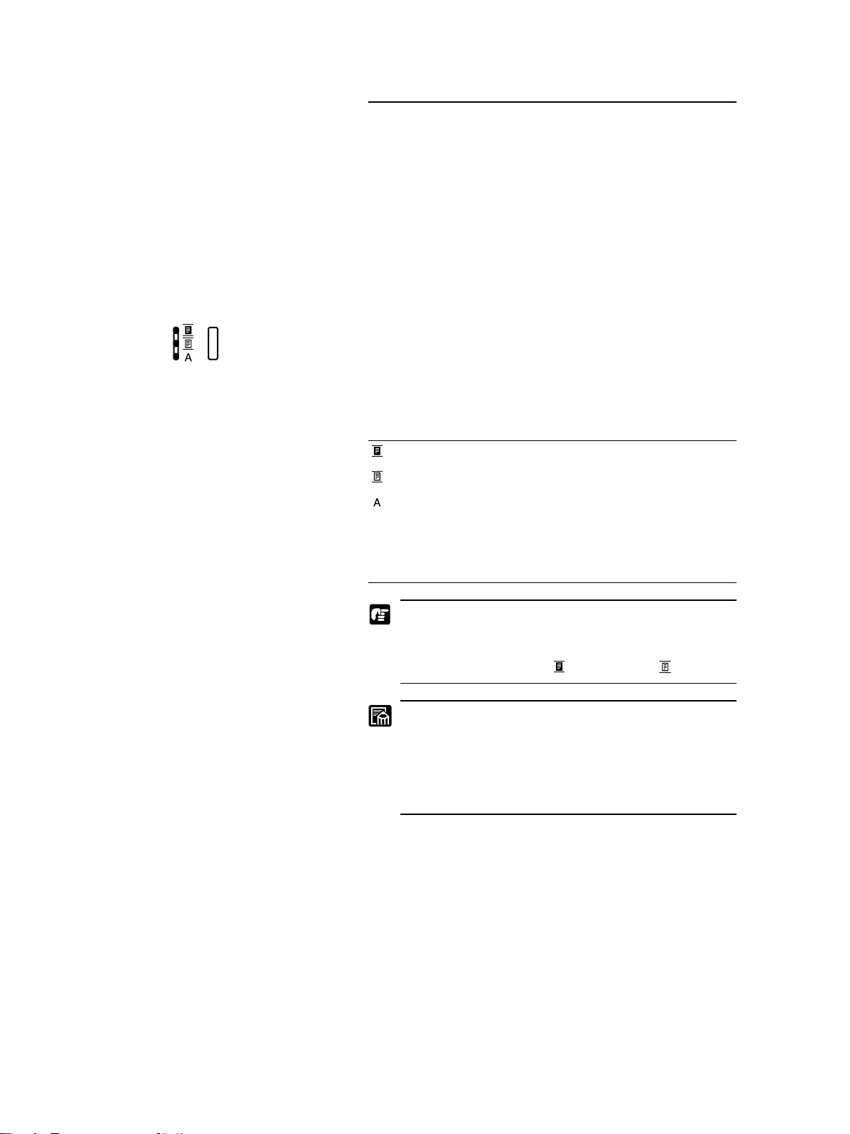
2. Select a positive or negative type film.
Press the Negative/Positive key to select a film mode.
The lamp to the left of the key and icons tells you the current
selection. Press the key and keep pressing it until the lamp next to
the selection you want lights.
Negative Prints positive on negative film.
Positive Prints positive on positive film.
Auto Automatically detects the type of film in
use and prints a positive image. If you
select Auto, the Negative or Positive
lamp blinks to tell you which type of film
has been detected.
The EZ-04 zoom lens has no function to automatically
switch between Negative and Positive. When using the
EZ-04 zoom lens, always use the Negative/Positive
switching key to select ( ) negative or ( ) positive.
Do not use Auto for an image with a grey or light border (where black and white may be difficult to distinguish), or if you intend to remove the border from the
image, trim the image, or define the area on the image
with the other keys. If you intend to use these special
functions, set Negative or Positive manually.
3. Display the image you want to print. Adjust the image so it is
within the print frame. (➞15)
4. Adjust the print density. You can let the unit adjust the print density automatically by pressing the AE key, or adjust it manually.
16
Page 21
OPERATING PROCEDURES
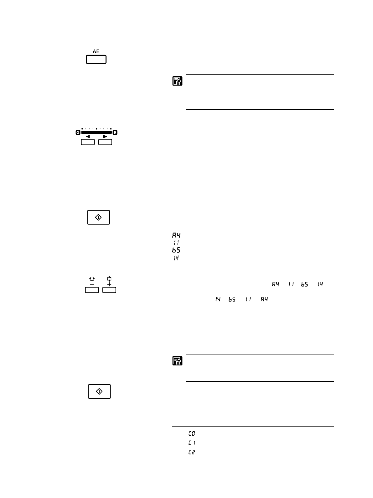
■ Automatic adjustment
Press the AE key on the keyboard or operation panel, so that the
lamp above the key comes on. The MS400 adjusts the print density automatically.
Even when using automatic adjustment, you can still
use the Print Density Adjustment keys to fine tune the
setting. The Print Density display changes accordingly.
You can fine tune to 17 different levels.
■ Manual adjustment
Make sure that the lamp above the AE key is off. (If necessary,
press the AE key so that the lamp goes off.) Then adjust the density by pressing the appropriate Print Density Adjustment key (right
arrow or left arrow) on the keyboard or operation panel. The Print
Density display changes accordingly, with rightward movement
indicating higher density. You can set to any of 33 levels.
5. Set the paper size that you want to print.
■ If you use Fileprint 250, please select paper size set on
the Paper Tray.
(1) Press the Clear/stop key and keep on for about 5 seconds to
enter the paper size setting mode. At that time, the current paper
size appears on the print display.
A4
Letter
B5
Legal
(2) When pressing plus (+) key of the print number setting key,
the display is changed in due order as ➞ ➞ ➞ . On
the other hand, when pressing minus (-) key, the display is changed
in due order as ➞ ➞ ➞ .
(3) Press the Clear/stop key to define paper size that you want to
use.
■ If you use Fileprint 400, please select the Paper Cas-
sette or Paper Tray you want to use.
The paper size to be set on the paper tray will be selected by a service technician at the installation of
Fileprint 400.
(1) Press the Clear/stop key and keep on for about 5 seconds to
enter the cassette select mode. At that time, the current paper cassette appears on the print display.
Print display Tray selection
Multipurpose tray selected
Upper cassette selected
Lower cassette selected
17
Page 22
OPERATING PROCEDURES
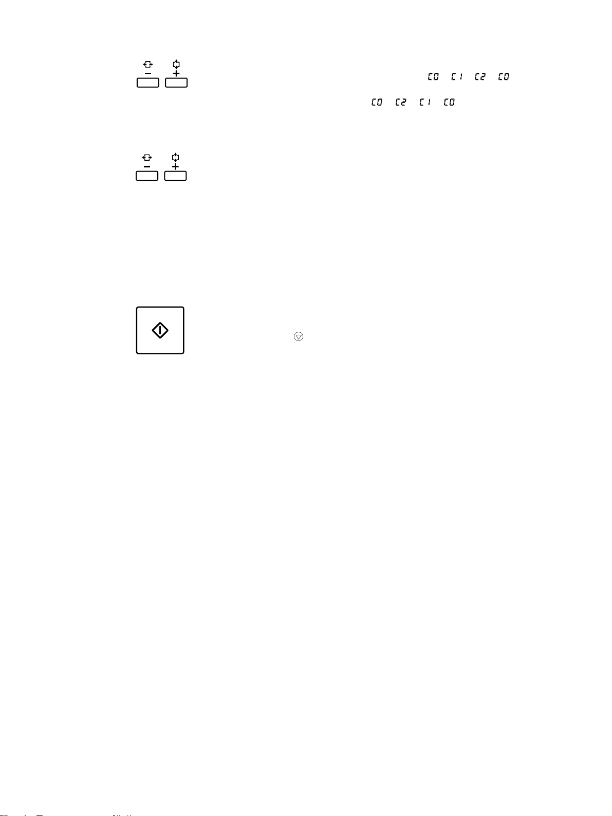
(2) When pressing plus (+) key on the print number setting key,
the display is changed in due order as ➞ ➞ ➞ . On
the other hand, when pressing minus (-) key, the display is
changed in due order as ➞ ➞ ➞ .
(3) Press the Clear/stop key to define paper size that you want to
use. At that time, the print number display returns to "01".
6. Set the number of print prints (01 to 99)
Press the Print keys to set the number of prints.
To increase or decrease the number of prints:
Press the plus key to increase the number.
Press the minus key to decrease the number.
To restore the default (1 copy):
Press the Stop/Clear key to reset the number of prints to 01.
7. You can also remove the border from the image or trim the image
(➞19, 20).
8. To start printing, press the Print Start key.
If you want to cancel printing at any time, press the Stop/Clear
key C/ .
18
Page 23
OPERATING PROCEDURES
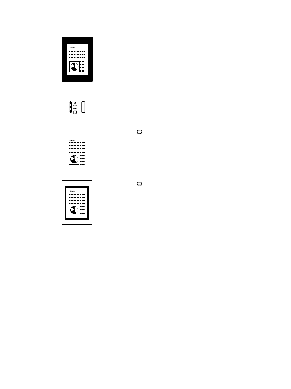
Setting automatic border removal
An image on negative film is displayed on the screen with a black
border around the image, and this black border will also appear in
your printed copy unless you remove it with the automatic border
removal function.
Remove these black borders around your images to avoid wasting
toner when the images are printed.
-orYou can also leave the border around the image but with very
little of the black color remaining.
Press the Border key to change the setting.
The lamp to the left of the Border key shows you the current se-
lection. To change the selection, press the Border key until the
lamp lights next to the selection you want to use.
( ) Select for removal of all black color around the image.
( ) Select for removing most of the black color around the im-
age.
Note the following restrictions on the use of this feature:
■ For images with ill defined borders, this function may not operate
correctly.
■ This function cannot be used when part of the image is outside the
print frame.
■ If several images are on the screen, the image other than the one
you want may print.
■ This feature cannot print a border larger than 5 mm around an
image.
19
Page 24
OPERATING PROCEDURES
;
;
;
;
Using trimming
Use the trimming feature to crop and print only a selected portion
of an image.
■ What is trimming?
Trimming means selecting only a portion of an image and cropping it for printing. Only the trimmed or cropped area of the image is printed. For example, you could trim a single article from a
full page of newspaper print and print only the article enclosed in
a trimmed rectangle.
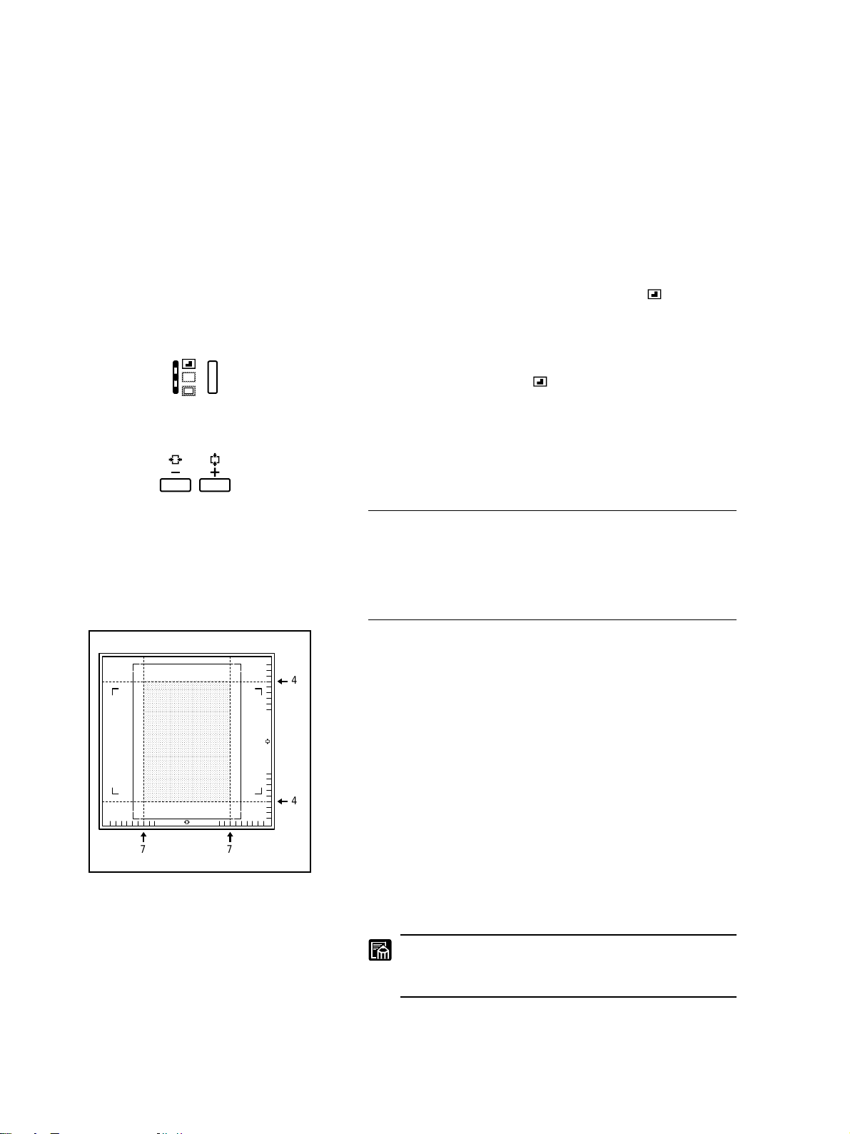
To select trimming, press the Border key on the operation panel
until the lamp next to the trimming icon lights ( ). Follow the
procedure below to define the area to the image to be printed.
■ Defining an area for trimming
1. Press and hold down the Border key for approximately 5 seconds
until the lamp for trimming (
The current area setting is shown in the Print display.
) starts blinking.
;;;
;;;
;;;
;;;
2. To adjust the area setting, press the Print Number Setting keys.
The starting point or origin for defining the screen area is the lower
right corner of the screen.
Plus key Press to move in the vertical direction. The
number in the Print display shows the current
screen vertical coordinate.
Minus key Press to move in the horizontal direction. The
number in the Print display shows the current
horizontal coordinate.
For example, the illustration shows the vertical set for 4 and the
horizontal set for 7. The shaded area is the area trimmed and se-
4
4
77
lected for printing.
3. To save the setting, press the Border Button. The setting remains
in effect even after the power is turned off and turned again.
If you have installed the optional Framing Kit, you cannot use this method to set an area on the screen. Use
the area setting tapes to define an area.
20
Page 25
;
;
;;
;
;;
OPERATING PROCEDURES
■ Setting an area with the area setting tapes (option)
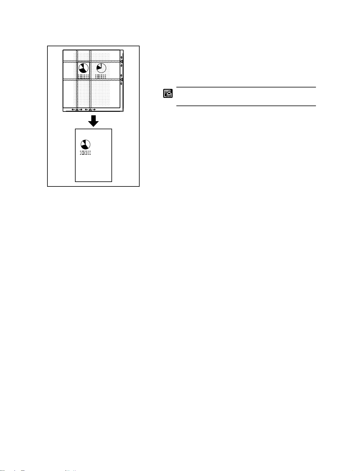
If you have installed the optional Framing Kit, you can use the
keys at the bottom and on the right side of the screen to select an
area for printing. There are 4 tapes on the screen you can move to
select an area for printing. The rectangle enclosed by the 4 tapes
is the area selected for printing.
;;
You can use this feature only after you have installed
the optional Framing Kit.
21
Page 26
MAINTENANCE AND TROUBLESHOOTING
■ Changing the halogen lamp.
■ Cleaning the main unit.
■ Reading and understanding errors and solving the problem.
MAINTENANCE AND
TROUBLESHOOTING
This section describes routine maintenance and troubleshooting
procedures:
To ensure optimum performance and a long service life for the
unit, perform the routine maintenance procedures described below.
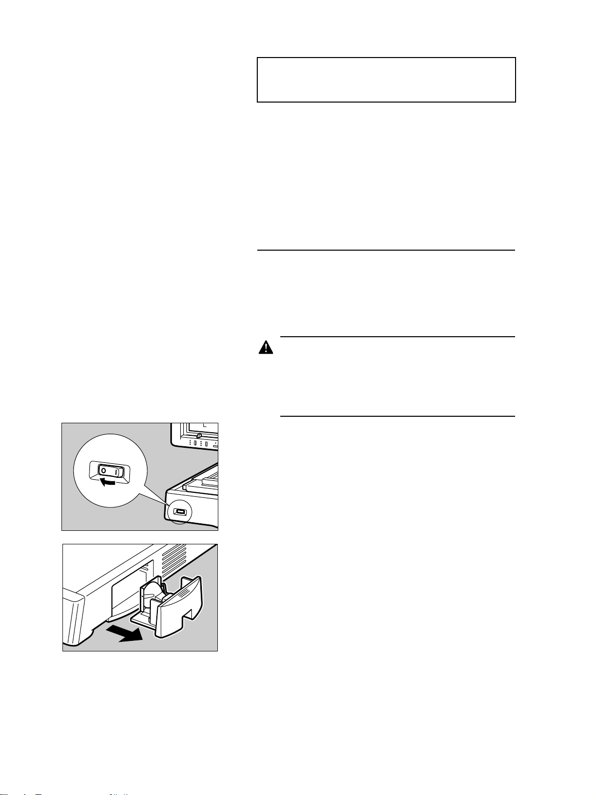
Changing the lamp
The halogen lamp projects the film image on the screen. If it burns
out, you will not be able to see images on the screen. Follow the
procedure below to change the lamp after it burns out.
If the lamp burns out, you will see L5 displayed in the Print dis-
play.
THE HALOGEN LAMP AND LAMP UNIT ARE EXTREMELY HOT. AFTER "L5" APPEARS IN THE
PRINT DISPLAY, WAIT A FEW MINUTES FOR THE
LAMP AND LAMP UNIT TO COOL DOWN BEFORE
YOU TURN OFF THE UNIT AND CHANGE THE
BULB.
1. If you do not see the image on the screen, check the Print display.
If you see L5 in the Print display, this confirms that the halogen
lamp has burned out. (➞26)
2. Wait about 5 minutes for the lamp and lamp unit to cool down.
Then turn off the unit.
3. On the right side of the unit, grip the lamp unit with firm pressure
and pull it from the main unit.
22
Page 27
MAINTENANCE AND TROUBLESHOOTING
IF THE LAMP IS STILL WARM, WAIT UNTIL THE
LAMP UNIT COOLS DOWN. HALOGEN LAMPS
BURN EXTREMELY HOT AND REQUIRE MORE
TIME TO COOL DOWN THAN ORDINARY BULBS.
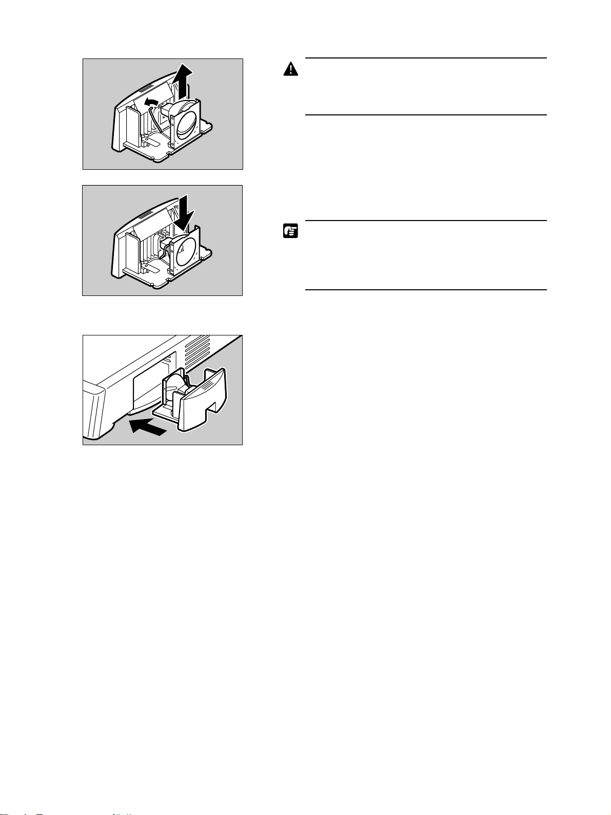
4. Push the side lever holding the halogen bulb to the side then lift
up the bulb.
5. Replace the halogen bulb only with a Canon specified replace-
ment.
Handle the new halogen bulb with extreme care. Do
not touch the surface of the new bulb with your bare
fingertips. Oil from your fingertips or other foreign matter can cause the bulb to burn unevenly, shortening
the service life of the halogen bulb.
While holding the company mark on the new halogen bulb up,
insert the bulb into the lamp unit.
6. Insert the lamp unit into the main unit with firm, even pressure
until it locks into place.
23
Page 28
MAINTENANCE AND TROUBLESHOOTING
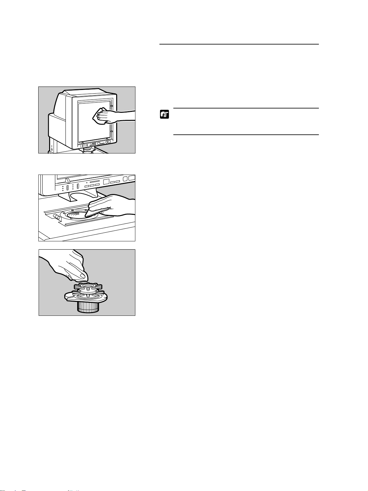
1. Turn the main unit off. Then remove the carrier and lens unit.
2. Use only a soft, dry cloth to wipe off the field lens.
Routine cleaning
Follow these simple procedures to clean the unit at least once a
day to ensure optimum performance and to guarantee a long service life for the main unit.
Cleaning the screen and main unit
Use a dry, soft cloth or a clean, slightly damp cloth to wipe off the
screen and body of the main unit.
To avoid damaging the surface of the main unit, never
use an organic solvent or cleaner to wipe down the
main unit.
Cleaning the lens
3. Use only a soft, dry cloth to wipe off the upper and lower surfaces
of the lens.
24
Page 29

MAINTENANCE AND TROUBLESHOOTING
Troubleshooting
If you detect a problem during operation of the main unit, check
the list of problems and possible solutions below.
Problem Solution
Screen does not come on, even after turning • Check the lamp unit and make sure it is set securely.
on the power switch. • Check the lamp to see if the lamp is burnt out. After the lamp
burns out, L5 is displayed. If the lamp is burned out, change the
halogen lamp. (➞22)
Screen brightness is uneven or too dark. • Check the lens and make sure it is clean.
• Check the lens and make sure it is securely installed.
• Check the lamp and lamp unit and make sure both are installed
securely.
• Check the setting of the Light Adjustment dial and make sure it
is set correctly for the type of lens installed. (➞11)
Image is out of focus. • Rotate the focus fin on the lens to adjust the focus. (➞15)
• Check the lens and make sure that it is installed correctly.
• Check the carrier and make sure that it is installed correctly. For
details, read the instructions you received with the carrier.
• Check the lens and lamp and make sure they are clean. If required, clean the lens or lamp
Image is skewed. • Rotate the rotation fin on the lens to adjust the image. (➞15)
• Check the carrier and make sure that it is installed correctly. For
details, read the instructions you received with the carrier.
After pressing the print key, print will not start. • If the Print display is blinking, this means the unit is warming up.
After the display lights and stays on, then the unit is ready to
use.
• If the Print display shows a User Call Error, look it up in the
table. (➞26)
25
Page 30
MAINTENANCE AND TROUBLESHOOTING
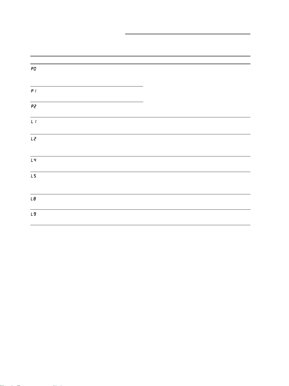
User Call Errors
Here is a list of User Call Errors. If you see a User Call Error in
the Print display, look it up in the table below.
Error Number
Meaning Solution
After removing a piece of jammed
paper, a sheet of paper is still
jammed in the printer.
A sheet of paper jam has occurred
inside the printer.
Two sheets of paper have jammed
inside the printer.
Paper is not set in the printer.
Toner in the toner cartridge is low,
or the toner cartridge is not installed
correctly.
The printer cover is open.
The halogen lamp on the main unit
has burned out or is not installed
correctly.
Wrong paper size in printer feed
tray.
Remove the jammed sheet from the printer. For
details, refer to your printer manual.
Supply paper to the paper cassette of the printer.
For details, refer to the printer manual.
Remove the toner cartridge and install it again. If
the message appears again, replace the toner cartridge. For details, refer to the printer manual.
Close the printer cover and make sure it locks in
place. For details see the printer manual.
Check the lamp installation and make sure it is installed correctly. If the error occurs again, replace
the halogen lamp. (➞22)
Re-load the tray with the correct paper size.
Printer power is not turned on, or a
test print is printing.
If the printer is off, turn the printer power switch on.
For details, see the printer manual.
26
Page 31
MAINTENANCE AND TROUBLESHOOTING
Service Call Errors
Every time you turn on the main unit, the unit automatically performs a self-diagnostic test. If the unit detects a problem at power
on, or at any other time during operation, it will display a Service
Call Error message in the Print display. A Service Call Error is a
three-digit number prefixed with the letter "E" (Ennn). A Service
Call Error message tells the service technician the source of the
problem.
Follow the procedure below when a Service Call Error occurs.
1. Note the Service Call Error in the Print display and turn the main
unit off immediately. Wait a few moments.
2. Turn the main unit on again and watch the display.
If you see a "1" in the Print display, the main unit has recovered
and you can resume normal operation.
When a service call error occurs, turning the main unit
off and on again frequently solves the problem.
If you see the Service Call Error again (Ennn), jot down the error
number, turn the main unit off immediately, then unplug the main
unit, printer, and/or carrier from the power source. Call for service and make sure you tell the service technician the number of
the Service Call Error displayed in the Print display.
27
Page 32

SPECIFICATIONS
SPECIFICATIONS
Microfilm Scanner 400
Main Unit
Type Desktop digital microfilm scanner
Screen 300 mm x 300 mm
Scanning method 400 dpi digital scanning
Film Negative, Positive, Negative/Positive auto switching
Lens magnification x7,x9.5-x16, x16-x32, x30-x55, x10-x24
Light source Halogen lamp (20V 150W)
Film
Type Silver film, diazo film, (blue/black)
Base density 0.6 to 1.4 for negative, 0.3 or less for positive
Image Adjustment
Focus/zoom/rotation Manual
Printing
Print size (USA or Canada) A4, Letter, Legal
Print size (other areas) A4
Density control AE, manual
Continuous printing 1 to 99
Print options Automatic border deletion, Trimming
General
Power AC 120V 50/60 Hz
AC 220-240V 50/60 Hz
Power consumption Max. 290W
Acoustic noise level Less than 70 dB
Work environment Room temperature: 10˚C to 32.5˚C (50˚F to 90.5˚F)
Humidity: 10% to 80%RH (without condensation)
Dimensions 668 x 442 x 541 mm (H x W x D)
Weight Approx. 26 kg
Options
Fixed lens EX7 (x7)
Zoom lenses EZ01 (x9.5-x16), EZ02 (x16-x32), EZ03 (x30-x55), EZ04 (x10-x24)
Carriers FC 190 RII, AC 100C, AC 100R, AC 100M
FS Controller I, FS Controller III, Roll Fiche Carrier 200
Framing Kit
Installation Kit
SCSI Board
Specifications subject to change without notice.
28
Page 33

INDEX
A
AE key
described, 12
Autocarrier 100C
described, 9
Autocarrier 100M
described, 9
Autocarrier 100R
described, 9
B
border
reduction, 12
removal, 12, 19
Border key
described, 12
trimming, 20
box
contents, 7
C
carrier
Autocarrier 100C, 9
Autocarrier 100M, 9
Autocarrier 100R, 9
Fiche Carrier 190RII, 9
FS Controller I, 9
FS Controller III, 9
recommended types, 9
Roll Fiche Carrier 200, 9
cleaning
lens, 24
main unit, 24
screen, 24
Clear/Stop key
described, 13
F
Fiche Carrier 190RII
described, 9
film
setting, 14
Frame Kit
option, 21
FS Controller I
described, 9
removing bottom cover, 11
FS Controller III
described, 9
power on first, 14
H
halogen lamp
changing, 22
handling, 23
removing, 22
I
image
adjusting, 15
enlarge/reduce, 15
focusing, 15
rotate, 15
L
lens
adjusting light for, 11
cleaning, 25
color label, 11
inserting, 10
removing, 10
switching, 10
types, 10
zoom, 10
location
choosing, 3
N
Negative/Positive key
described, 12
P
power
power on/off, 14
power source
recommended, 5
selecting, 5
print density
adjusting, 16
auto adjustment, 17
auto selection, 12
display, 12
manual adjustment, 17
Print display
described, 13
displays errors, 13
Print number setting key
described, 13
Print Start key
described, 13
printer
recommended, 8
printing
adjusting print density, 16
auto mode selection, 12
manually adjusting print density, 17
positive on negative film, 12
postive on positive film, 12
prints, 17
selecting pos/neg film, 16
starting, 16
R
Roll Fiche Carrier 100
described, 9
S
safety
warnings, 6
Service Call
defined, 13
table, 27
specifications
table, 28
T
trimming
defined, 20
Frame Kit, 21
setting, 20
troubleshooting
table, 25
U
User Call
defined, 13
table, 26
Z
zoom
lens, 10
29
Page 34

30
 Loading...