

Page 1

2002 X440s OWNER'S MANUAL
P/N 951-5002032
Page 2
S a fe ty A le rts
• FAILURE TO FOLLOW THE WARNINGS CONTAINED IN THIS MANUAL CAN RESULT IN SERIOUS INJURY OR
DEATH.
• Keep this Owner’s Manual in a safe place.
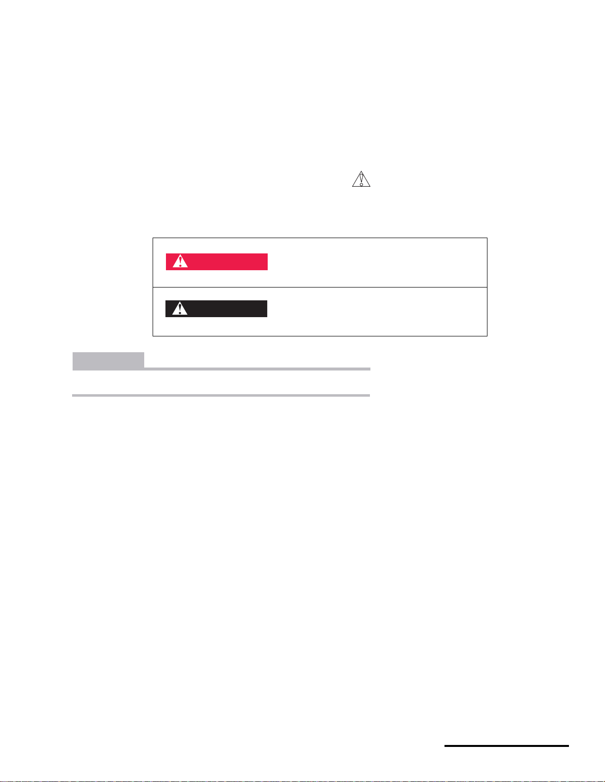
MESSAGES WITH THE SAFETY ALERT SYMBOL
• Pay special attention to all messages preceded by the Safety Alert Symbol.
It means: ATTENTION! BECOME ALERT! YOUR SAFETY IS INVOLVED.
Indicates that severe personal injury or
DANGER
death WILL result if instructions are not
followed.
WARNING
CAUTION
Indicates a potential hazard could resul t in vehicle dam age if instructi ons are not follo wed .
NOTE : Provides helpful information
Indicates a potential hazard that COULD
result in serious injury or death.
1
P/N 951-05002032
Printed : 8/13/01
Page 3

Contents
Safety Alerts . . . . . . . . . . . . . . . . . 1
Contents . . . . . . . . . . . . . . . . . . . . 2
Important Information . . . . . . . . .3
Pre-Ride Inspection . . . . . . . . . . . 6
Component Locations . . . . . . . . . 7
Controls . . . . . . . . . . . . . . . . . . . . 8
Operating . . . . . . . . . . . . . . . . . . . 11
Fluids. . . . . . . . . . . . . . . . . . . . . . . 14
Brake . . . . . . . . . . . . . . . . . . . . . . . . . . . 14
Coolant . . . . . . . . . . . . . . . . . . . . . . . . . . 16
Engine oil . . . . . . . . . . . . . . . . . . . . . . . . 18
Transmission oil . . . . . . . . . . . . . . . . . . . 23
Fuel. . . . . . . . . . . . . . . . . . . . . . . . . . . . . 26
Maintenance and Adjustments . .27
Break-in . . . . . . . . . . . . . . . . . . . . . . . . . 27
Panels. . . . . . . . . . . . . . . . . . . . . . . . . . . 30
Air . . . . . . . . . . . . . . . . . . . . . . . . . . . . . . 35
Fuel. . . . . . . . . . . . . . . . . . . . . . . . . . . . . 38
Brakes. . . . . . . . . . . . . . . . . . . . . . . . . . . 43
Exhaust. . . . . . . . . . . . . . . . . . . . . . . . . . 46
Clutch . . . . . . . . . . . . . . . . . . . . . . . . . . . 47
Drive . . . . . . . . . . . . . . . . . . . . . . . . . . . . 49
Electrical. . . . . . . . . . . . . . . . . . . . . . . . . 56
Steering . . . . . . . . . . . . . . . . . . . . . . . . . 65
Suspension. . . . . . . . . . . . . . . . . . . . . . . 66
Rear shock . . . . . . . . . . . . . . . . . . . . . . . 69
Tires & Wheels. . . . . . . . . . . . . . . . . . . . 73
Frame, Sub-frame, Swingarm. . . . . . . . . 75
Lubrication . . . . . . . . . . . . . . . . . . . . . . . 76
Cleaning and Storage . . . . . . . . . 83
X440s Model Specifications . . . . 85
X440s Service Specifications . . .86
X440s Torques . . . . . . . . . . . . . . . 87
X440s Owner's Manual.fm
© 2001 Cannondale Corporation - All Rights Reserved
2
Page 4

Imp or ta nt
In fo r ma tion
available at the time of publication. Cannondale Corporation
reserves the right to make changes at any time, without
notice.
This vehicle has U.S. and Internation al patents pending.
Cannondale Motorspo rts
Cannondale Corporat ion
We strongly suggest that you do the following before
operating the vehicle:
• READ and UNDERSTAND this Owner’s Manual.
• Perform the Pre-Ride Inspection found in this
manual.
• Wear appropriate protective gear - approved full
faced helmet, gloves, boots, long-sleeve shirt,
pants). Consider specially designed protective offroad vehic le riding apparel.
ABOUT THIS MANUAL
The purpose of this manual is to provide the owner with
important safety, service, maintenance, and tuning
information, and s hou ld be thoroughly read before operating
or working on the vehicle.
This manual is divided into sections which contain easy-tofollow procedures which are reasonably straight-forward.
Anyone with the mechanical ability and the proper tools
should be able to perform them. Each procedure is
accompanied by illustrations and photos to aid in proper
vehicle operation, basic maintenance, tuning, etc.
• Read and understand the entire procedure before
performing an y work. If you are unfamiliar with or
doubt your o wn abilities to co mplete a pro cedure as
described, have an authori zed Cannondale
motorsports dealer service y our vehicle.
Please keep your Owner's Manual in a safe and convenient
place, and consider it an integral part of your vehicle.
For detailed servicing information refer to the Service
Manual for your vehicle or contact an authorized
Cannondale motorsports dealer for a list of available
publications. If this manual is lost or damaged, contact an
authorized Cannondale motorsports dealer for a
replacement.
LIMITATIONS
EXPERIENCED RIDERS ONLY
• This vehicle is not f or b egin ner s.
All Cannondale motorsports products are designed for use
by trained and experienced riders only. All are very high
performance, competition sport machines and should only
be operated by licensed competition riders in excellent
physical condition, who are well-trained and experienced in
the operation of high perform an ce competition vehicles.
GOOD JUDGEMENT
There is always a risk involved when riding a vehicle;
however, making sure you and the vehicle are in the best
condition possible w il l ens ure a gre at riding ex pe rien ce. Use
sound judgement wh en ridi ng.
Never ride under the influence of alcohol, medication, or
drugs. Doing so will greatly reduce your ability to properly
operate this vehicle and could lead to an accident, injury,
and/or death. If you are taking medications prescribed by
your doctor, consult him/her before riding.
MODIFICATIONS
We recommend that you do not substitute parts, change or
modify your vehicle. Such changes could seriously impair
your vehicle’s handling, stability, and braking, making it
unsafe to ride and causing serious injury and/or vehicle
damage.
NO PASSENGERS
Do not overload this vehicle or carry passengers. Doing so
could seriously impair your vehicle’s handling, stability, and
braking, making it unsafe to ride which could result in
damage to the vehicle or serious injury or death to the
operator and/or passenger.
Meticulous engineering and aggressive product designs
represent the spirit of innovation - always a driving force at
Cannondale. All information, illustrations, and specifications
in this manual are based on the latest product information
3
P/N 951-05002032
Printed : 8/13/01
Page 5
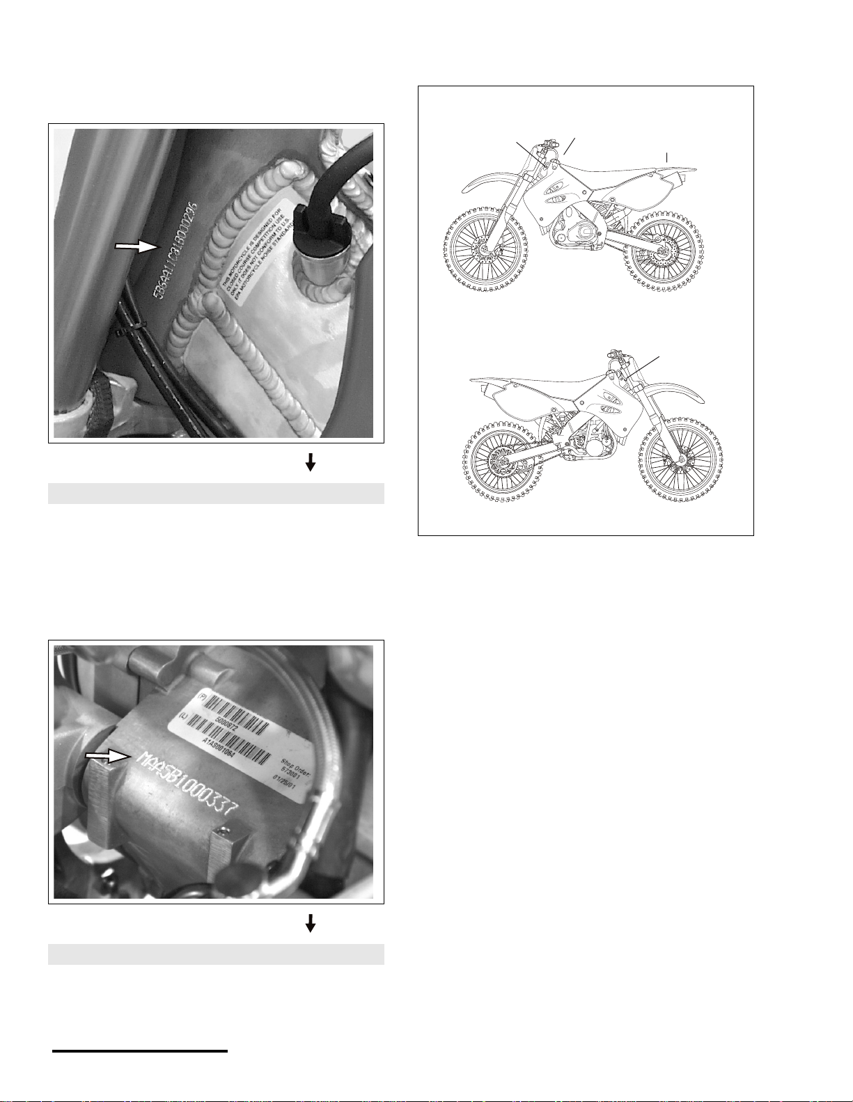
V EHICLE IDENTIFICATION NUMBER (VIN)
XXXXXXXXXXXX
XXXXXX
XXXXXX
The vehicle identification number ( VIN) is located on the left
side of the steering head.
XXXXXXXXXXXX
Record your vehicle’s ID number here:
LABEL LOCATIONS
3
2
1
4
ENGINE SERIAL NUMBER
The engine serial numb er i s etche d/s tam pe d into th e eng ine
crankcase.
XXXXXXXXXXXX
Record your vehicle’s ID number here:
See illustration on following page for examples of the
numbered labels abov e.
X440s Owner's Manual.fm
© 2001 Cannondale Corporation - All Rights Reserved
4
Page 6
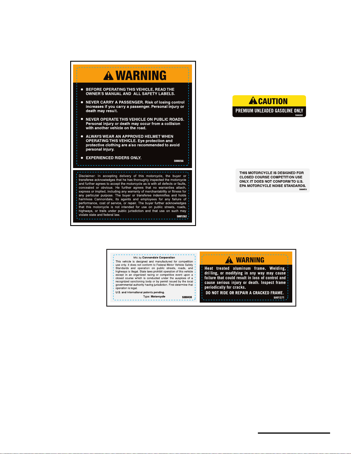
LABELS
(1)
(2)
(3)
1. General
2. Fuel
3. EPA noise
4. Frame
(4)
5
P/N 951-05002032
Printed : 8/13/01
Page 7
Pre-Ride
Inspection
WARNING
POTENTIAL HAZARD
Failure to inspect vehicle before operating.
WHAT CAN HAPPEN
Increases the possibility of equipment failure
resulting in a accident where you can be seriously
injured or killed.
HOW TO AVOID THE HAZARD
Always inspect before operating.
Always follow the inspection and maintenance
procedures found in this Owner’s Manual.
Have an authorized Cannondale Motorsports Dealer
inspect your veh ic le at le ast e very 25 ho urs of ridin g.
SUSPENSION
fork legs . . . . . . . . . . . (wear, damage,settings, oil leaks)
rear shock. . . . . . . . . .(wear, damage, settings, oil leaks)
WHEELS
wheels . . . . . . . . . . . . . . . . . . . . . . . . . . . . . . . (damage)
spokes . . . . . . . . . . . . . . . . . . (correct tension, damage)
TIRES
physical. . . . (tread conditions, wear, damage, punctures,
tears)
pressure . . . . . . . . . . . . . .(correct, regulate if necessary)
BODY PANELS
seat . . . . . . . . . . . . . . . . . . (damage, installed correctly)
plastics . . . . . . . . . . . . . . . . . . . . . . . . .(secure, damage)
FASTENERS
bolts, fasteners . . . . . . (tightened to the specified torque)
PRE-RIDE CHECKLIST
FLUIDS
brake fluid . . . . . . . . . . . . . . . . . . . . . . . . . . (level correct)
coolant . . . . . . . . . . . . . . . . . . . . . . . . . . . . (level correct)
engine oil . . . . . . . . . . . . . . . . . . . . . . . . . .(level correct)
transmission oil. . . . . . . . . . . . . . . . . . . . . .(level correct)
Fuel cap tightened securely
Inspect vehicle for leaks and repair if necessary.
BRAKES
Front/rear brakes . . . . . . . . . . . . . . . . . .(proper function)
Front/rear pads . . . . . . . . . . . . . . . . . . . . (damage, wear)
Front/rear discs. . . . . . . . . . . . . . . . . . . . (damage, wear)
THROTTLE
lev e r freepl ay. . . . .(as specified in all steering positions ))
proper operation . . . (smooth and returns to idle (clos ed)
position across the entire
steering range)
CLUTCH
clutch lever freeplay . . . . . . . . . . . . . . . . . . (as specified)
actuating arm . . . . . . . . . . . . . . . . . . . . (correct position)
DRIVE
sprocket conditions. . . . . . . . . . . . . . . . . (damage, wear)
chain condition . . . . . . . . . . (damage, wear, stretch limit)
chain sag . . . . . . . . . . . . . . . . . . . . . . . . . . (as specified)
clean and lubricate the chain
chain rollers . (cracks, excessive wear, or other damage)
chain guide block . . . . .(cracks, excessive wear, or other
damage)
swingarm buffer . . . . . .(cracks, excessive wear, or other
damage)
X440s Owner's Manual.fm
© 2001 Cannondale Corporation - All Rights Reserved
6
Page 8
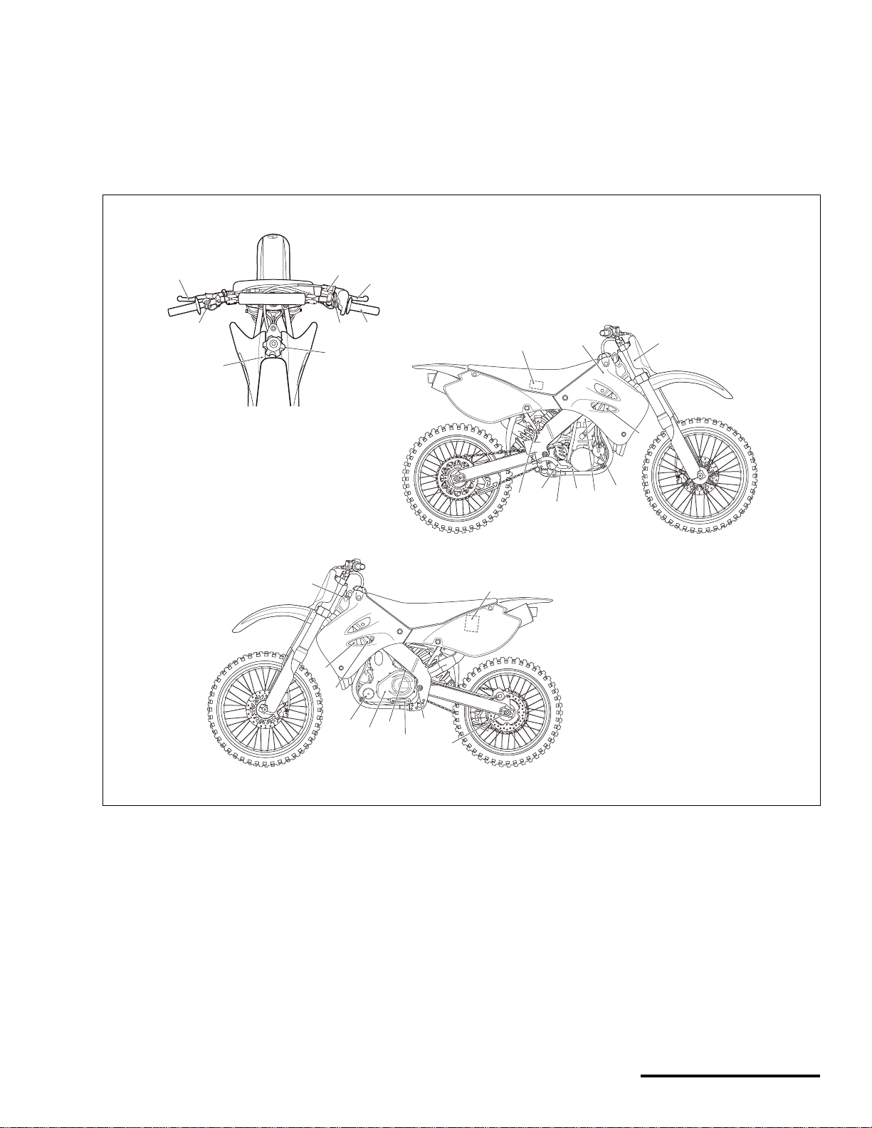
Component
Locations
1
2
3
5
6
4
7
19
20
21
8
22
25
24
23
27
28
26
9
10
18
17
1. Clutch lever
2. Engine stop button
3. Front brake master cylinder
4. Engine start button
5. Front brake lever
6. Throttle
7. Fuel tank cap
8. Fuel tank
9. Engine oil fill
10. Battery
11. Drive chain adjusters
12. Engine oil drain (frame)
14
13
12
11
7
16
15
13. Shift lever
14. Transmission oil fill
15. Clutch
16. Engine oil filter
17. Idle adjusting screw
18. Radiator
19. Engine Control Module (ECM)
20. Airbox filter
21. Main air filter
22. Fuel injectors
23. Starter clutch cover
24. Water pump
25. Engine oil crankcase drain
26. Transmission oil drain
27. Brake pedal
28. Rear brake reservoir
P/N 951-05002032
Printed : 8/13/01
Page 9
Controls
CLUTCH LEVER
The clutch lever is located on the left handlebar. Pull the
lever to disengage the clutch. Release the lever to engage
the clutch. The lever should be pulled quickly when
disengaging and slo wly when engaging.
ENGINE STOP BUTT ON
The engine stop button is located on the left handlebar. The
button is (RED) in color. Push it to stop the engine. Make
sure this button functions properly before you begin riding.
NOTE : The stop button is normally a closed circuit switch.
If the stop switc h is damag ed or the wires a r e fray ed or torn,
(circuit open) the engine may not sta r t.
1
1. Engine stop button
NOTE : When starting it is recommended that you shift the
transmission into neutral and pull in the clutch lever to
increase the starte r’s efficiency.
1
1. Clutch lever
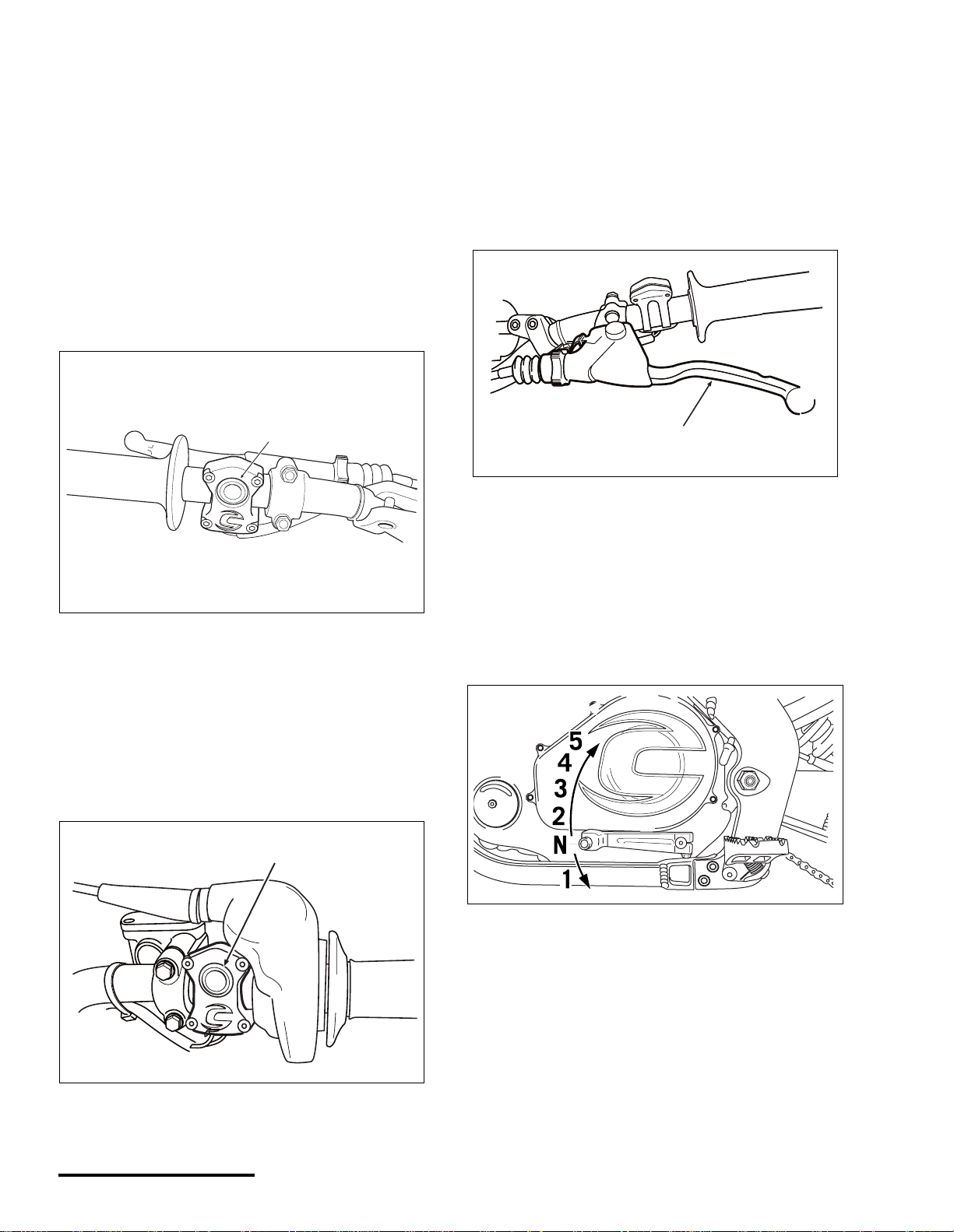
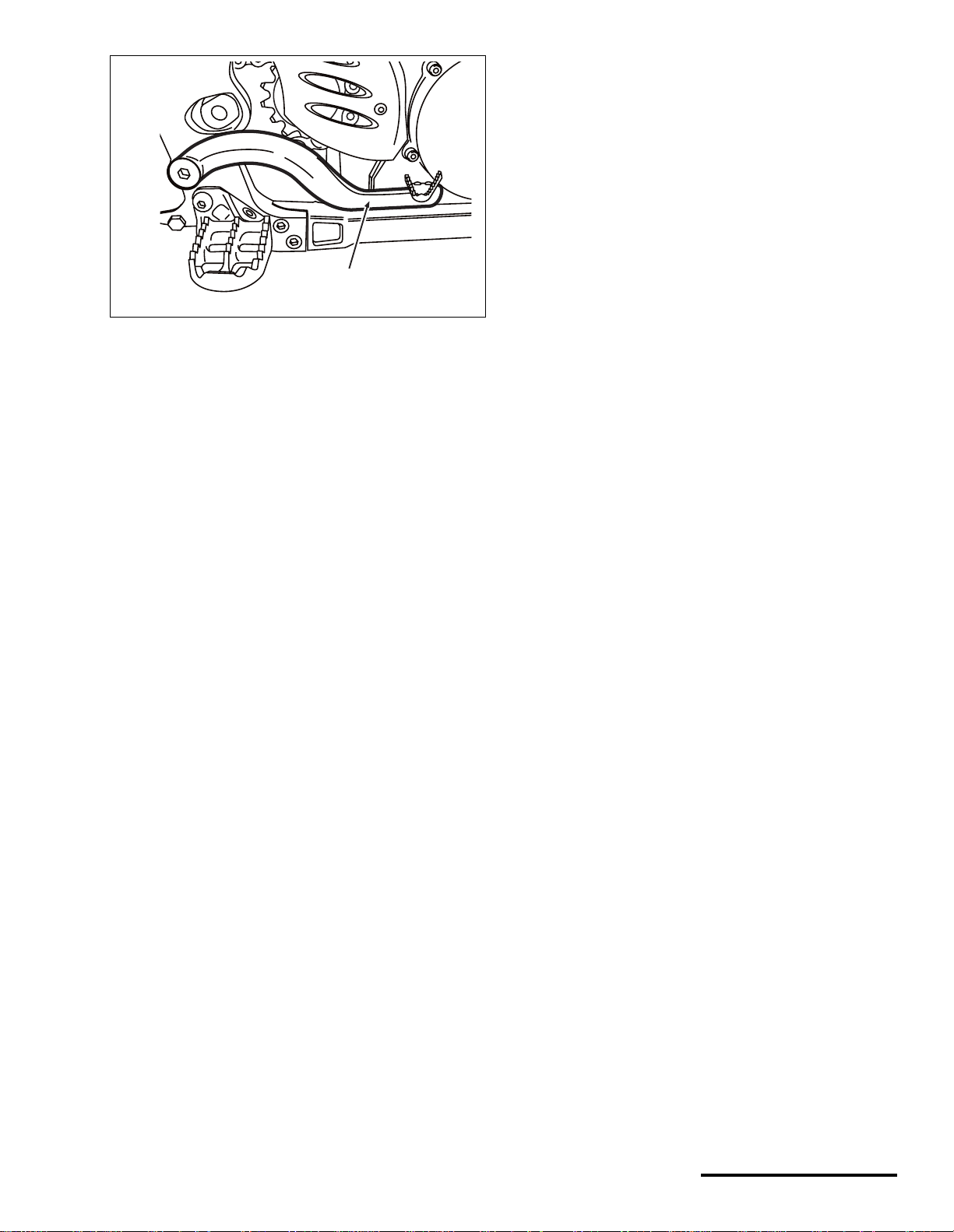
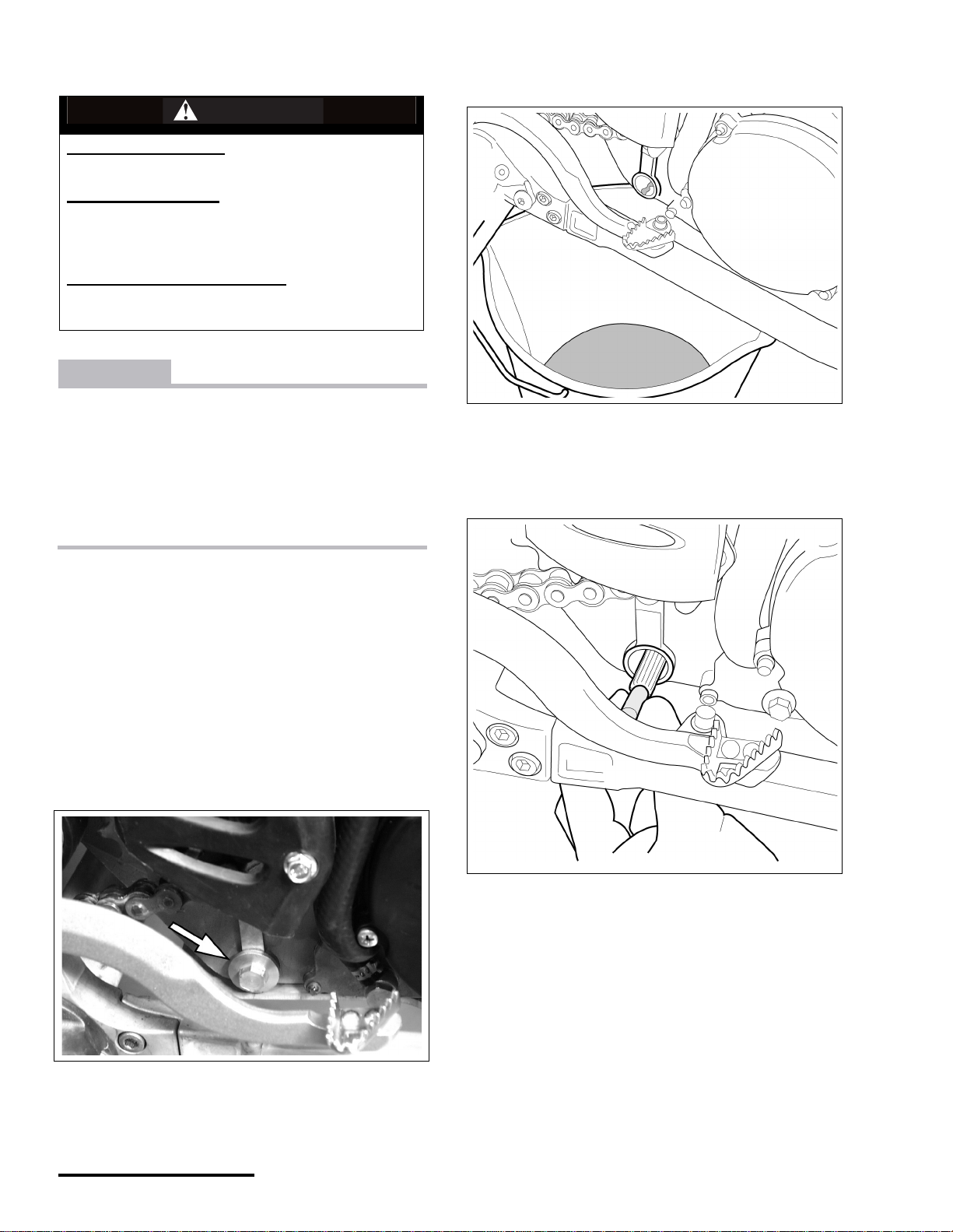
SHIFT LEVER
The shift lever is located on the left side of the engine.
NOTE : The tra n smission is commonly referred to as a “one
down, four up” transmission. Neutral is located between first
and second gears.
ENGINE START BUTTON
The engine start button i s locat ed on the rig ht handl ebar and
is (GREEN) in color. Pressing it activates the starter motor.
NOTE : When using the button, hold it for no more than 2-3
seconds at a time.
1
1. Engine start button
X440s Owner's Manual.fm
© 2001 Cannondale Corporation - All Rights Reserved
8
Page 10
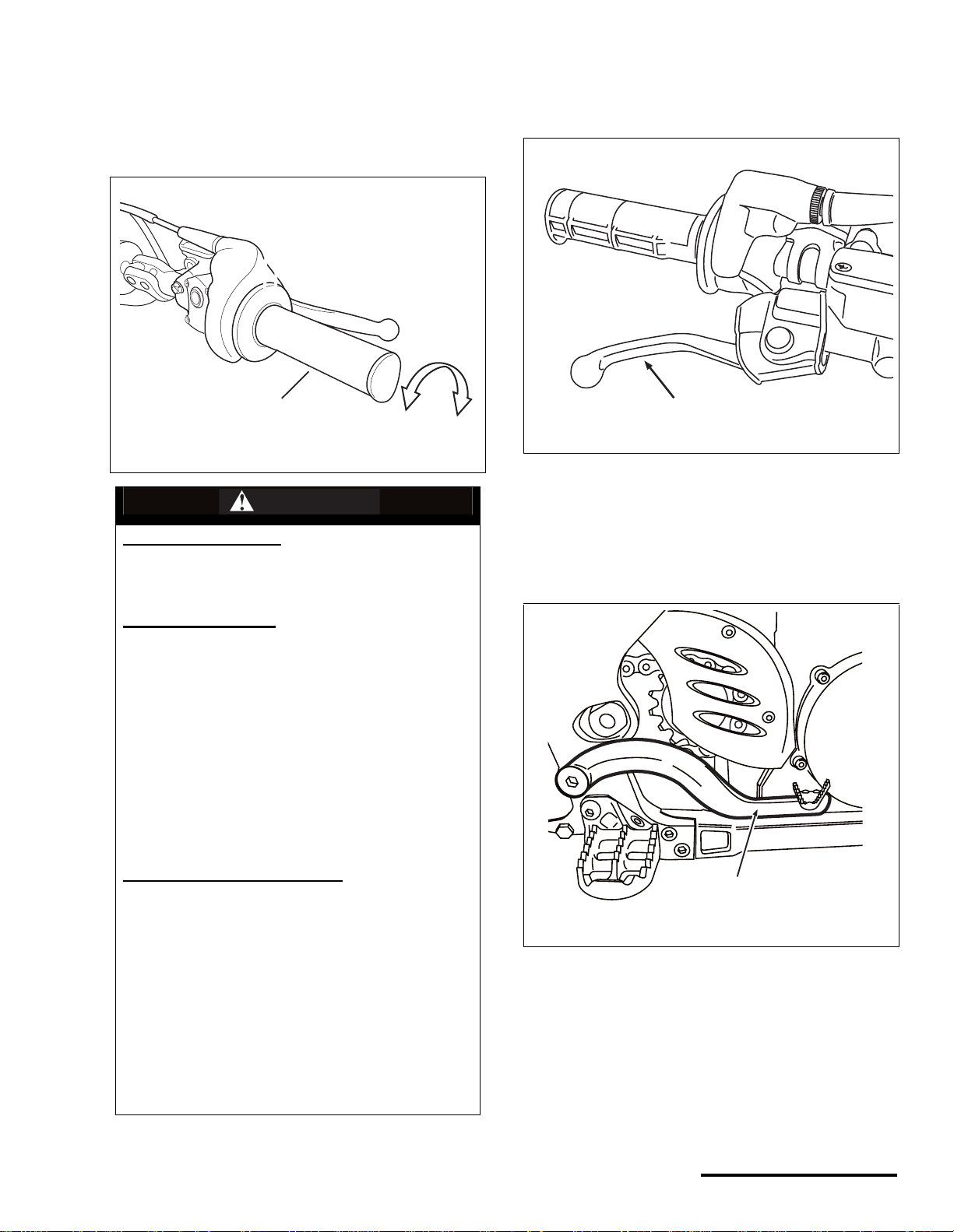
THROTTLE
1
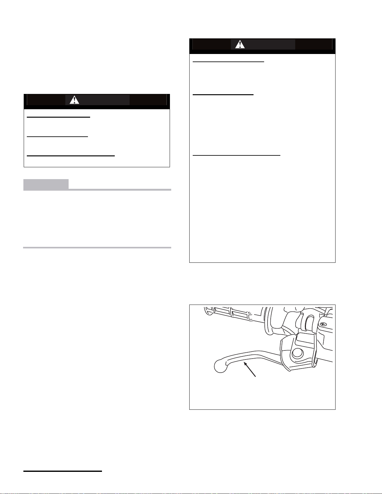
FRONT BRAKE LEVER
The throttle lever is located on the right handlebaand
controls acceleration and deceleration of the engine. To
accelerate, turn the grip toward you. To decelerate, turn the
grip away from you.T
1
a
b
WARNING
POTENTIAL HAZARD
(1) Malfunctioning throttle
(2) Incorrect freeplay
The front brake lever is located on the right handlebar. Pull
the lever toward you to activate the front brake.
1
1. Front brake lever
REAR BRAKE PEDAL
The rear brake pedal is located on the right side of the
vehicle. Press it firmly to apply the rear brake.
WHAT CAN HAPPEN
(1) The throttle must return to to the closed position
when you release it. If it sticks you can lose the
ability to accelerate and decelerate the engine
which could result in an accident where you could
be seriously injured or killed.
(2) The throttle freeplay must be maintained as
specified, otherwise the engine speed could
increase when the handlebars are turned or when
the throttle is slightly grasped. Either situation
could result in an unexpected acceleration of the
engine where you could be seriously injured or
killed.
HOW TO AVOID THE HAZARD
(1) Test the operation of the throttle before each ride.
Make sure it operates smoothly (with no sticking or
binding) in all steering positions. It should return
automatically to the closed position when relea se d.
(2) Make sure the throttle freeplay is adjusted as
specified. See “throttle Freeplay” starting on
page 38.
(1 & 2) If the throttle malfunctions or you can not
adjust the throttle to the specified freeplay, do not
ride the vehicle. Contact an authorized Cannondale
motorsports for servicing.
1. Rear brake pedal
9
P/N 951-05002032
Printed : 8/13/01
Page 11
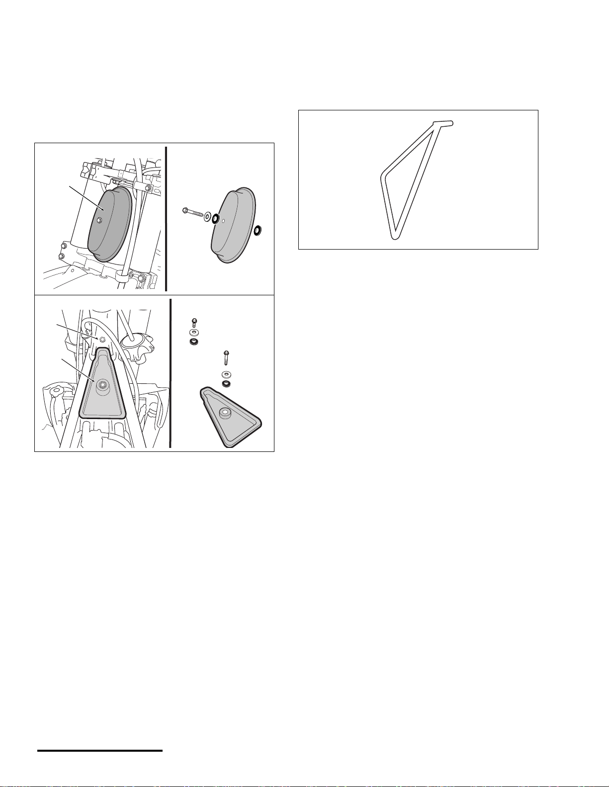
AIR FILTER CLEANING PLUGS
SIDE STAND
The air filt er cleaning plugs ar e provided with yo ur vehicle
and must be installed when washing/cleaning the
motorcycle. These plugs will help guard against water and
other contaminants entering the engine. Make sure the
sealing foam on the plug is in good condition. See the
cleaning section of this manual for how to install the plugs
properly.
1
2
The side stand is used to support the vehicle when not in
use. It is only designed to support the weight of the vehicle;
do not apply extra weight when using it (e.g., leaning on the
bike) Be sure to remove it before starting out.
3
1. Steering head plug
2. Fuel tank bolt hole plug
3. Airbox plug
X440s Owner's Manual.fm
© 2001 Cannondale Corporation - All Rights Reserved
10
Page 12

Operating
This section explains basic operating and riding methods
(i.e., starting, stopping, and shifting). If after reading this
manual or at anytime you hav e any q uestio ns rega rding ho w
to operate the vehicle, contact an authorized Cannondale
motorsports dealer for assistance.
WARNING
POTENTIAL HAZARD
Failure to inspect vehicle before operating.
WHAT CAN HAPPEN
Increases the possibility of equipment failure
resulting in a accident where you can be seriously
injured or killed.
STARTING
DANGER
POTENTIAL HAZARD
Running the engine indoors.
Breathing exhaust gases
WHAT CAN HAPPEN
Running the engine indoors will expose you to
dangerous exhaust gases. Breathing carbon
monoxide gas leads to poisoning, asphyxiation, and
death. This will happen rapidly and without notice.
HOW TO AVOID THE HAZARD
Never operate the vehicle indoors even for brief
periods.
BATTERY (FULLY CHARGED)
HOW TO AVOID THE HAZARD
Always ins pec t before operating.
Always follow the inspection and maintenance
procedures found in this Owner’s Manual.
Have an authorized Cannondale Motorsports Dealer
inspect your vehicle at least after every 25 hours of
use.
CAUTION
Allow the engine to reach operating temperature
before riding.
This vehicle does not have a cooling fan. Airflow
across the radiator is maintained during riding. If
the vehicle runs without airflow, the engine can
overheat and be severely damaged. The time it
would take to overheat will depend on the weather
conditions. Do not allow your vehicle to idle for
more than 3 minutes without airflow across the radiator.
• Make sure the battery is at full charge. Why? If the
battery voltage dr ops wh ile you are using the
starter motor, the v olta ge could drop and the power
relay of the ECU will shut the ECU off. When this
happens, the engine will turn over but not start.
COLD STARTING - (MC1000 )
NOTE : MC1000 equipped unit utilize an idle air control
valve which automatically adjust throttle air bypass for cold
starts. Do not open the throttle when cold starting.
1. Shift transmission into NEUTRAL and pull-in and hold
in the clutch lever.
2. Press and hold the engine start button for no more
than 2 to 3 seconds at a time.
When the engine fires release the button and slowly
release the clutch lever.
11
P/N 951-05002032
Printed : 8/13/01
Page 13
STARTING A WARM ENGINE
BRAKING
When starting an engine after it has reached operating
temperature, do not open th e th rottl e. This wi ll m ak e s tart ing
very difficult a nd pos si bly foul the spark plug.
SHIFTING GEARS
WARNING
POTENTIAL HAZARD
Shifting to a lower gear at high speeds.
WHAT CAN HAPPEN
Tires can lose traction and cause an accident.
HOW TO AVOID THE HAZARD
Do not down shift at high speeds.
CAUTION
When shifting gears, press the shift lever firmly to
make sure the gears engagement is complete.
Careless shifting can result in incomplete gear
engagement and can cause the transmission to
jump out of gear. This can severely damage the
engine.
1. To engage first gear from NEUTRAL, pull in the clutch
lever and push down on the shift lever.
2. Release the shift lever.
3. Open the throttle a little and slowly let out the clutch
lever.
WARNING
POTENTIAL HAZARD(S)
(1) Using the brakes improperly.
(2) Wet brake system (e.g. discs, pads)
WHAT CAN HAPPEN
(1) If you apply the brakes too quickly or suddenly
the wheels may slide or skid possibly causing you to
lose control resulting in an accident where you
could be seriously injured or killed.
(2)Wet brakes do not provide the stopping power
needed and therefore are extremely dangerous.
HOW TO AVOID THE HAZARD
(1) Apply the front and rear brakes evenly and
gradually. Always consider the surface of the terrain
you are riding on and how it will affect your braking
ability. Concentrate on applyin g both brakes as har d
as possible without skidding. Shift down or fully
disengage the clutch as necessary to keep the
engine from stalling.
(2) In wet conditions test the brake operation
frequently. When riding in wet conditions, ride the
vehicle at sl ow spe eds an d ap ply th e b rake s seve ral
times until they are dry and at full power. Before
riding the vehicle m ake su re the b rakes an d controls
(e.g., brake lever, brake pedal, clutch lever, engine
stop switch, and throttle) operate properly.
To brake, close the throttle completely with the clutch
engaged (except when shifting gears) so the engine will
help slow down the vehicle. Apply the front and rear brakes
evenly.
4. To shift into a higher gear, pull in the clutch lever, push
the shift lever up to the next gear, release the shift
lever, then release the clutch lever.
5. To shift into a lower gear, pull in the clutch lever, push
down on the shift lever and release - then release the
clutch lever.
X440s Owner's Manual.fm
© 2001 Cannondale Corporation - All Rights Reserved
1
1. Front brake lever
12
Page 14
1. Rear brake pedal
1
STOPPING
When stopping the vehicle, pull in the clutch lever while
completely closing the throttle, shift the transmission into
neutral, and press the en gin e stop switch with your thumb.
AFTER YOU RIDE
1. After riding the vehicle, clean it thoroughly and allow it
to dry , and th en inspect th e entire veh icle for da mage or
loose fasteners.
2. Repair or tighten any damaged or loose comp onents
and lubricate the vehicle .
3. If the vehicle is damaged, it is recommended that you
put tape over the start button to remind you to not
start the vehicle. Also, attach a piece of paper to the
handlebar with the problem written on it.
13
P/N 951-05002032
Printed : 8/13/01
Page 15
Fluids
BRAKE
SERVICE : Brake, fluid type, DOT #4
CAUTION
Avoid spilling brake fluid on painted, plastic or rubber parts; damage can result. Place a shop towel or
rag over these parts when servicing the brake system. Any wipe up spills immediat ely.
FRONT BRAKE
1. T o ch ec k the front system, start by leveling the top of
the master cylinder (mounted on the right handlebar).
WARNING
POTENTIAL HAZARD(S)
(1) Eye and skin injury, death if swallowed.
(2) Not using the specified, mixing different types (or
brands) of, and using unsealed containers of brake
fluid.
(3) Inadequate brake fluid levels.
WHAT CAN HAPPEN
(1) Brake fluid is a hazar dous substance. It can cause
injury to your ey es or skin if you touch it. If swallo we d
it can cause death.
(2) Using unspecified brake fluid can damage the
brake system leaving you without brakes. A container
of brake fluid once unsealed can begin to absorb
moisture from the atmosphere - if used in the brake
system, the moisture will reduce braking force. You
could lose your brakes an d hav e an accide nt resulting
in injury or death.
(3) Low brake fluid can allow air to enter the system
and this will reduce braking power. Again, you could
have an accident and be serio usly injured or killed.
HOW TO AVOID THE HAZARD
(1) Always wear eye and hand protection when
working with brake fluid. Keep brake fluid out of the
reach of children and animals. If ingested contact
contact a doctor immediately.
2
1
3
CLEAN BEFORE OPENING!
1. Master cylinder
2. Site window
3. ‘LWR’ mark
2. Inspect the fluid level through the site glass. If the
fluid level is below the ‘LWR’ mark, add the specified
brake fluid until the fluid is at the top of the window.
3. To add fluid, remove the screws, cover and
diaphragm from the master cylinder. Pour DOT#4
brake fluid from a sealed container into the resevoir.
Pour only until the fluid level rises to the top of the site
window and no higher. If you fill above the window
(2) Always use DOT 4 brake fluid from a sealed
container. Don’t mix fluids or use opened fluids.
Have the system drained and refilled by an authorized
Cannonadale Motorsports dealer if you suspect fluids
have been mixed acciden tally .
(3) Check for proper brake operation and fluid level
before riding the vehicle.
X440s Owner's Manual.fm
© 2001 Cannondale Corporation - All Rights Reserved
14
Page 16
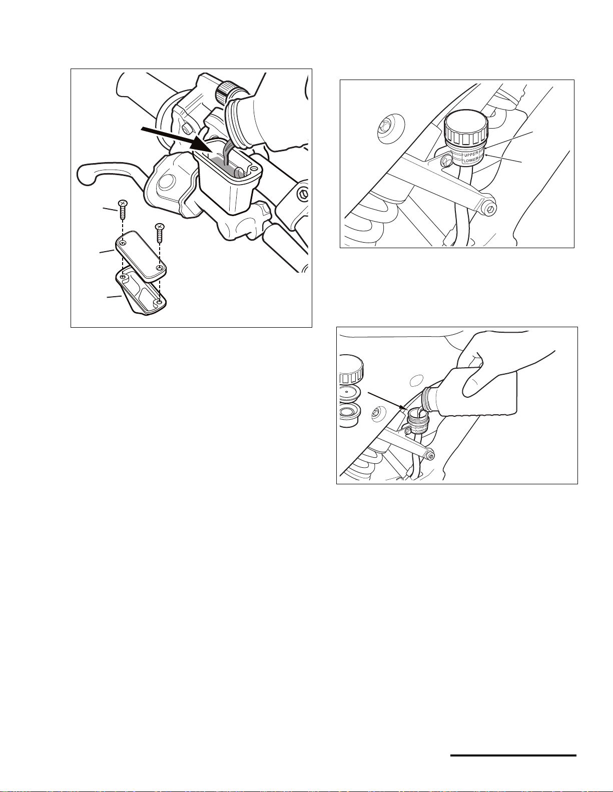
fluid will spill when you re-install the diaphram and
4
cover.
POUR TO
TOP OF
WINDOW
DOT
1
2. If the fluid level is below the ‘UPPER’ mark, add
specified brake fluid until it reaches the ‘UPPER’
mark.
2
1
2
3
1. Front brake master cylinder cover screws
2. Front brake master cylinder cover
3. Diaphragm
4. Reinstall the front brake master cylinder diaphragm
and cover. Tighten front master cyli nd er cove r scre ws
to the specified torque.
TORQUE : Brake, master cylinder, front, cover screws
1.9 N•m (1.4 lbf•ft)
REAR BRAKE
1. To check the rear system, level the rear brake master
cylinder reservoir. The fluid level should be above the
‘LOWER’ mark.
1. ‘LOWER’ mark
2. ‘UPPER’ mark
NOTE : Do not fill the brake master cylinder above the
‘UPPER’ mark or the fluid will overflow when the diaphragm
is installed.
DOT 4
1. Reservoir cap
2. Diaphragm plate
3. Diaphragm
3. Install reservoir diaphrag m, diaphragm plate and cap.
15
P/N 951-05002032
Printed : 8/13/01
Page 17
COOLANT LEVEL
COOLANT
SERVICE : Coolant, type
Anti-freeze Ethylene glyc ol with corrosion
inhibitors fo r alumin um en gines
SERVICE : Coolant, mixture ratio
1:1 (coolant/distilled water)
WARNING
POTENTIAL HAZARD(S)
(1) Scalding coolant sprayed onto YOU
(2) Serious eye or skin injury
WHAT CAN HAPPEN
(1) You can be severely burned by coolant sprayed
out from under high pressure if the bottle is
opened while the system is hot.
(2) Coolant is poisonous. If it gets in your eyes or
contacts your skin the fluid can cause irritation or
severe injury.
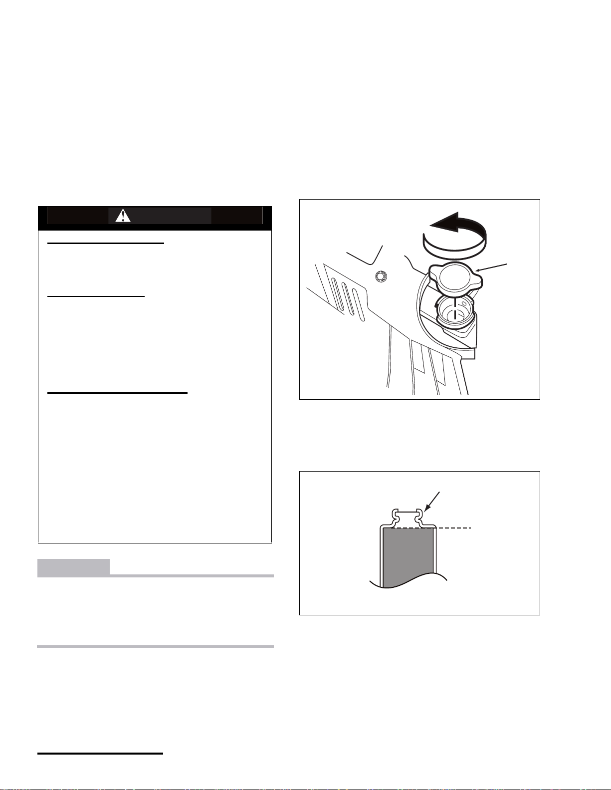
1. To check the level, make sure the engine and radiator
are cold.
2. Place a thick towel over the radiator cap.
3. Slowly turn the cap in direction (a) until you feel the
cap reach the detent; this will allow any residual
pressure to escape. Allow all pressure to escape
before continuing.
Press down on the cap and keep turning it until it can
be removed.
a
1
HOW TO AVOID THE HAZARD
(1) Wait for engine to cool before removing the cap
or servicing the coolant system. Be sure to wear
eye protection, a long-sleeve shirt, and hand
protection (e.g. rubber gloves) when working with
coolant.
(2) Always wear eye protection and protective
clothing when working with any components of
the cooling system. Keep coolant away from
children and pets. Call a doctor immediately if
coolant is swallowed and induce vomiting. Flush
eyes and skin with water if coolant gets in eyes or
comes into contact with skin.
CAUTION
Operating the vehicle with a leaky or faulty cooling
system can result in severe engine damage. Always
use the specified coolant.
If the coolant level drops significantly, bleed the system after adding.
NOTE : We recommend that you bleed the coolant system
each time you add fluid.
1. Radiator cap
a. Loosening direction
4. Coolant level should be at the bottom of the filler
neck. Add if necessary.
1
1. Filler neck
X440s Owner's Manual.fm
© 2001 Cannondale Corporation - All Rights Reserved
16
Page 18
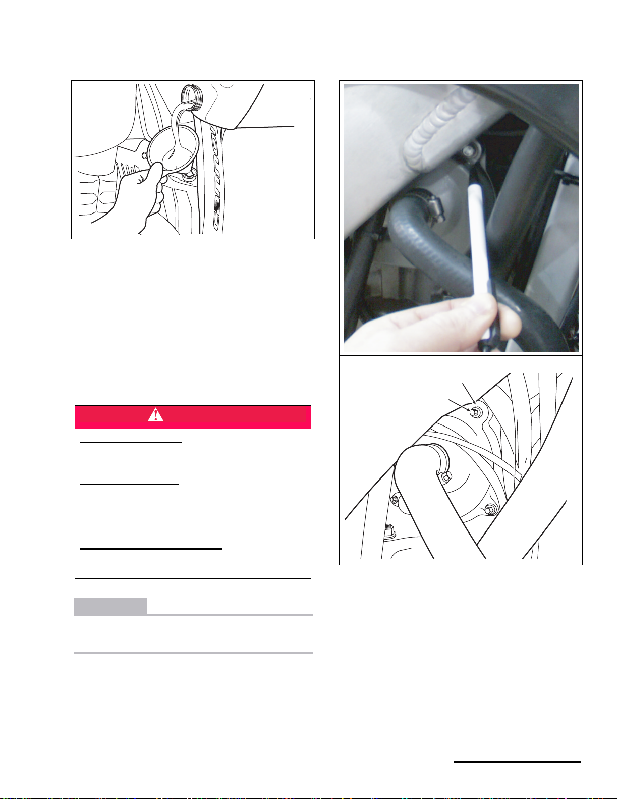
5. To add, add the specified coolant at the radiator filler
hole using a clean funnel. Wipe up any spill ed cool ant
with a clean shop towel.
6. Reinstall the radiator cap.
7. Check the entire cooli ng system for le aks.
8. If the coolant level drops after adding and no leaks
are found, contact an authorized Cannondale
Motorsports dealer for servicing.
4. Loosen the bleed bolt on the water pump cover and
allow any trapped air to escape. It is not necessary to
remove the bolt.
BLEEDING THE COOLANT SYSTEM
DANGER
POTENTIAL HAZARD
Running the engine indoors.
Breathing exhaust gases
WHAT CAN HAPPEN
Running the engine indoors will expose you to
dangerous exhaust gases. Breathing carbon
monoxide gas leads to poisoning, asphyxiation, and
death. This will happen rapidly and without notice.
HOW TO AVOID THE HAZARD
Never operate the vehicle indoors even for brief
periods.
CAUTION
Do not over-tighten the bleed bolt and check the
condition of the sealing washer. If it leaks, replace it.
1
2
1. Sealing washer
2. Bleed bolt
5. When no more air is coming out of the bolt hole; only
coolant, tighten the bleed bolt. Add coolant at the
radiator to bring to proper level if necessary.
6. Reinstall the radiator cap.
1. Make sure the engine and coolant system are cold.
2. Place vehicle on a stand.
3. Remove radiator cap.
17
7. Start engine and allow to idle for three minutes and
briefly touch the radiator. If the radiator is warm, the
cooling system was ble d properly . If the radiator is still
cool, stop the engine. Repeat the bleed procedure
and check again.
P/N 951-05002032
Printed : 8/13/01
Page 19
ENGINE OIL
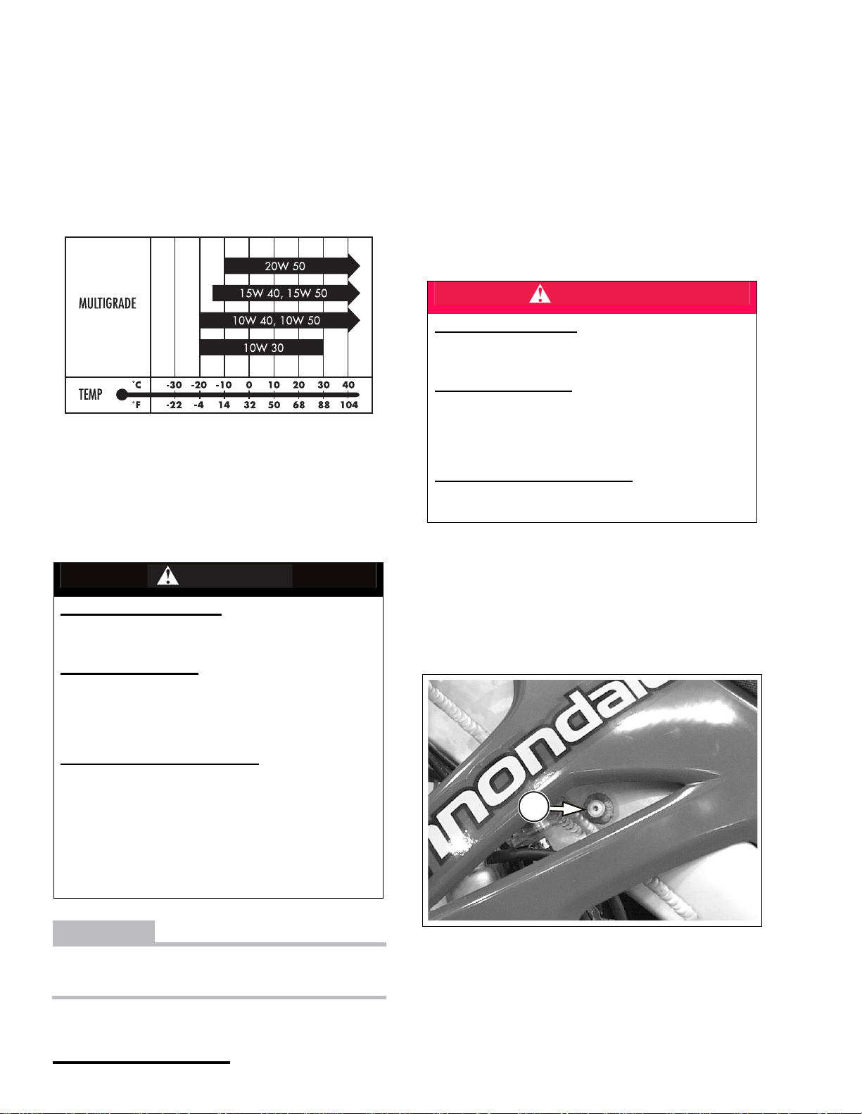
SERVICE : Engine, oil recommended
Synthetic or semi-synthetic, 10W-40.
SERVICE : Engine, oil, total quantity,
1.3 US qt. (1.2 L)
SERVICE : Engine, oil, change, quantity (* see note
below)
1 US quart (0.9 L)
NOTE : * When adding engine oil following a change (i.e.
drain of the spars, crankcase, filters removal and cleaning),
small volumes of oil can remain within the spar reservoirs.
Keep this fact in mind and be careful not to over fill the
system. The change quantity specified here provides
sufficient oil to operate engine safely so that level may be
checked in the spar.
Be careful not to overfill the engine oil. Pour small amounts
rechecking the le ve l b etw e en pours. Place vehicle on a level
surface.
CHECKING T H E EN GI NE OI L
DANGER
POTENTIAL HAZARD
Running the engine indoors.
Breathing exhaust gase s
WHAT CAN HAPPEN
Running the engine indoors will expose you to
dangerous exhaust gases. Breathing carbon
monoxide gas leads to poisoning, asphyxiation, and
death. This will happen rapidly and without notice.
HOW TO AVOID THE HAZARD
Never operate the vehicle indoors even for brief
periods.
1. T o check, place the vehicle on a stan d so it is le ve l.
WARNING
POTENTIAL HAZARD(S)
Serious injury or irritation to the skin or eyes.
Death if swallowed.
WHAT CAN HAPPEN
Engine oil is a hazardous substance. If it comes into
contact with your skin or eyes you can suffer
serious injury or irritation. If it is swallowed it can
cause death.
HOW TO AVOID THE HAZARD
Wear hand protection and safety glasses when
working with engine oil.
If you touch engine oil, wash it off immediately with
soap and water.
Clean clothes or rags contaminated with engine oil.
If swallowed seek immediate medical attention.
KEEP ENGINE OIL AWAY FROM CHILDREN AND
ANIMALS.
CAUTION
The correct oil level can only be checked after the
engine has run for a 1 minute.
2. Shift the transmission into NEUTRAL and start the
vehicle. Allow to run for 1 minute at idle speed, then
turn the engine off.
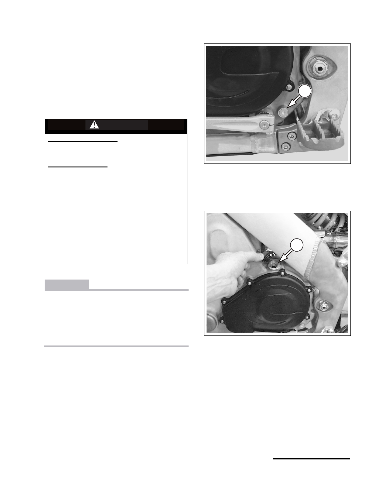
3. Remove the engine oil level check bolt.
1
1. Engine oil level check bolt (left frame spar)
X440s Owner's Manual.fm
© 2001 Cannondale Corporation - All Rights Reserved
18
Page 20
4. The engine oil level should be even with the bo ttom of
the check hole. Add if necessary.
LEFT FRAME
SPAR
CORRECT
CHECK BOLT
HOLE
OIL LEVEL
AFTER 1 MINUTE
CHANGING THE ENGINE OIL
DANGER
POTENTIAL HAZARD
Running the engine indoors.
Breathing exhaust gases
WHAT CAN HAPPEN
Running the engine indoors will expose you to
dangerous exhaust gases. Breathing carbon
monoxide gas leads to poisoning, asphyxiation, and
death. This will happen rapidly and without notice.
HOW TO AVOID THE HAZARD
Never operate the vehicle indoors even for brief
periods.
WARNING
5. To add, remove the filler ca p on the left frame spar
and pour the specified engine oil until the level
reaches the bottom of the check hole. Pour slowly to
allow the oil to flow throughout the spar.
2
1
1. Engine oil filler cap (left frame spar)
2. Vent hose
6. Reinstall the check bolt.
TORQUE : Frame, engine oil spar check bolt
15.0 lbf•ft (20.3 N•m.
POTENTIAL HAZARD
Blindness, eye injury,
WHAT CAN HAPPEN
When cleaning the oil filters, objects propelled by
compressed air can strike your eyes and cause
serious injury or blindness.
HOW TO AVOID THE HAZARD
Wear safety glasses when working with compressed
air.
1. Place the vehicle on a stand.
2. Start engine and allow to reach normal operating
temperature 158°F (70°C).
3. Turn the engine off.
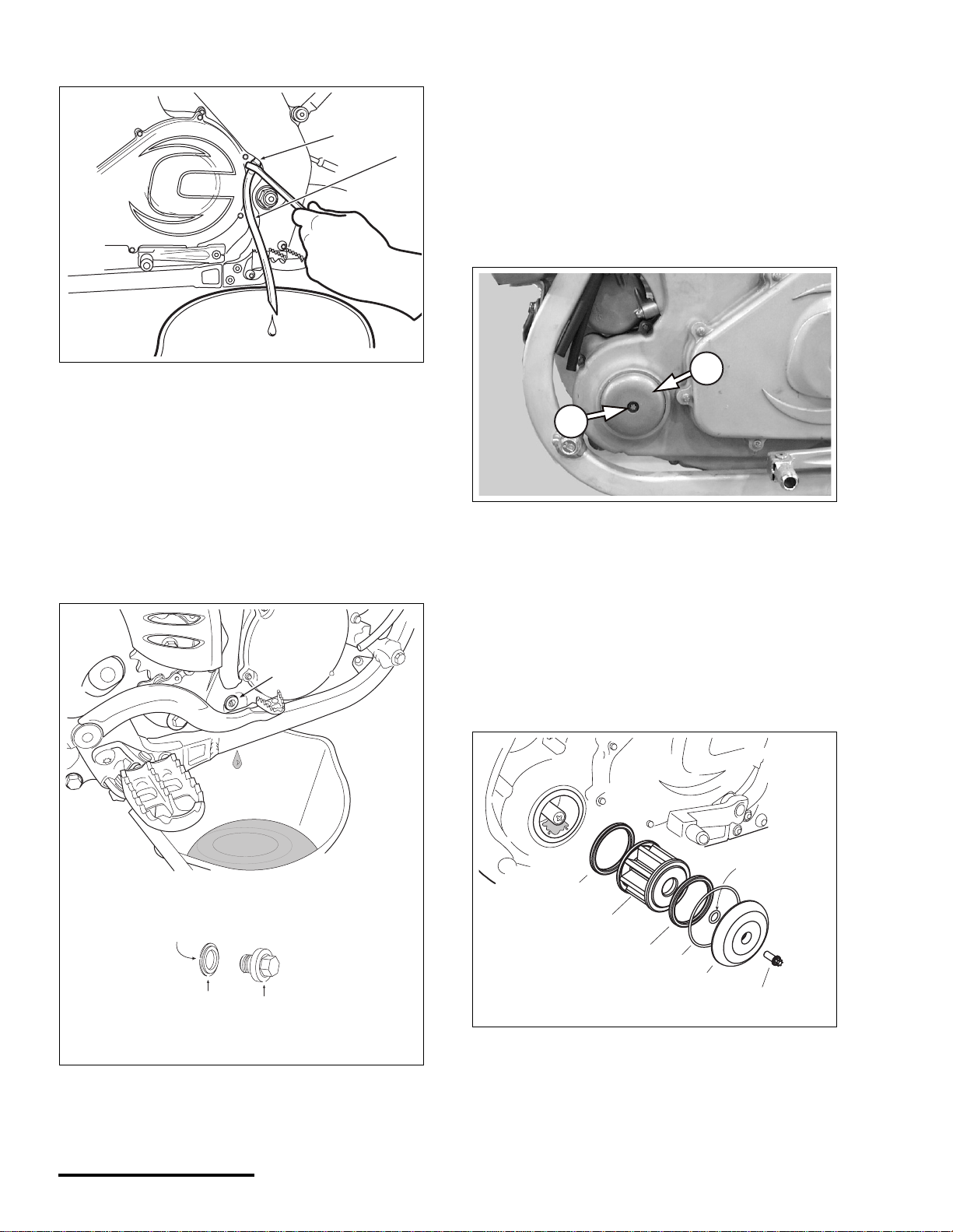
4. Place an oil pan under the left frame spar drain bo lt.
5. Connect a clear plastic hose to the engine oil drain
bolt and loosen it
6. Allow the contents of the spar to drain completely into
an oil pan.
19
P/N 951-05002032
Printed : 8/13/01
Page 21
NOTE : Remove the spar oil filler cap to facilitate draining.
1
2
that the flat side faces the crankcase and install.
Tighten to the spe ci fie d torqu e.
TORQUE : Engine, engine oil drain bolt (crankcase)
6.0 lbf•ft (8.1 N•m)
10. Now, place a container under engine oil filter cover
and remove bolt and engine oil filter cover.
NOTE : Be sure to note the two cover O-rings as you
remove the cove r.
1. Engine oil drain plug (left spar)
2. Clear hose
7. Tighten the bolt.
TORQUE : Engine, engine oil drain bolt (left spar)
15.0 lbf•ft (20.3 N•m)
8. Place a container under engine oil crankcase drain
bolt located on the right side of the engine and
remove it and the sealing washer. Allow the oil to
drain completely.
1
2
1
1. Filter cover bolt
2. Filter cover
11. Remove the seal, filter (screen) and seal from the
filter housing.
12. Clean the filter using compressed air and clean the
the filter housing cavity with a clean shop towel.
13. Inspect the seals and filter element for tears, cracks,
and other damage. Replace new if damaged.
FLAT SIDE
SEALING
BOLT
WASHER
1. Bolt
2. Sealing washer
9. Apply anti-seize compo und to t he threa ds of th e drain
bolt. Then install the sealing washer onto the bolt so
X440s Owner's Manual.fm
© 2001 Cannondale Corporation - All Rights Reserved
1. Bolt
2. Cover
3. O-ring (2-011)
4. O-ring (2-033)
5. Filter seal
6. Filter (screen)
20
3
5
6
5
4
2
1
Page 22
14. Apply a light coat of O-ring grease to the large and
small cover O-rings and insert them back into the
cover.
15. Use some O-ring grease to “stick” the filter seals s o
that they are centered on the filter. This will help
assure that the seals remain in place when you insert
the filter into the housing.
16. Install the cover and cover bolt.
CAUTION
Do not over-tighten the cover bolt. You will damage
the threads of the filter housing. If the cover leaks,
you may need to replace the cover O-rings or
inspect the cover and housing mating surfaces for
damage.
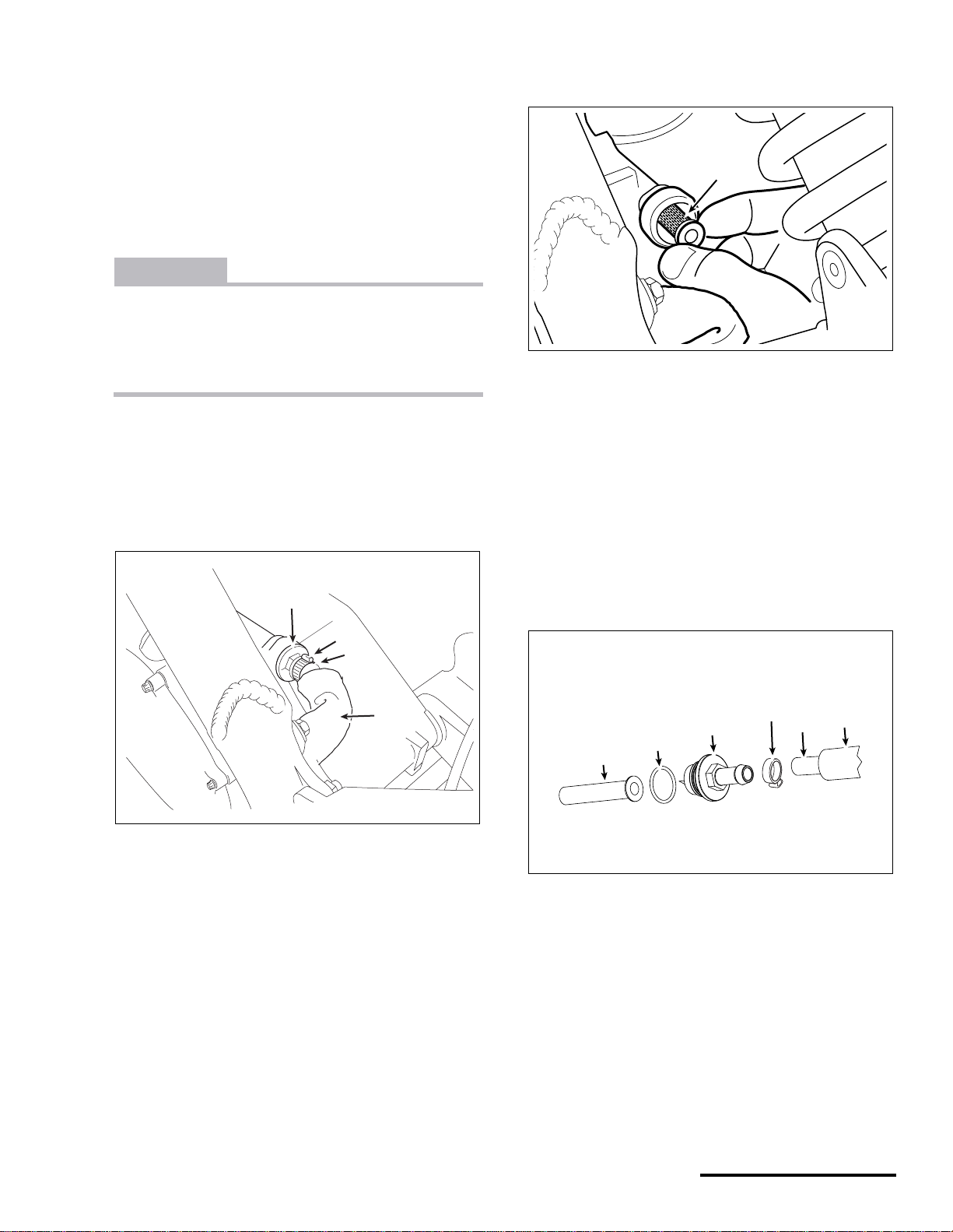
18. Loosen and remove the inlet fitting. Then, remove the
inlet filter (screen) from the crankcase hole.
1
1. Inlet filter (screen)
19. Clean the screen using compressed air.
TORQUE : Engine, engine oil, filter cover bolt
3.3 lbf•ft (4.5 N•m)
17. Now, carefully work the heat shield back to expose
the left spar return hose and clamp. Then, remove the
clamp and the hose from the engine oil inlet fitting.
4
3
2
1
1. Heat shield
2. Spar return hose
3. Clamp
4. Inlet fitting
20. Inspect the inlet fitting, 0-ring, and inlet screen for
tears, cracks, and other damage. Replace any
damaged part with a new one.
21. Reinstall the filter into the crankcase. Inspect the
fitting O-ring and replace it with a new one if
necessary.
22. Apply light coat of clean engine oil to the fitting O-ring
install the fitting. Tighten it to the specified torque.
3
4
6
5
2
1
1. Screen
2. O-ring
3. Inlet fitting
4. Clamp
5. Spar return hose
6. Heat shield
21
TORQUE : Engine, engine oil inlet fitting
18.0 lbf•ft (25.0 N•m)
23. Reinstall the engine oil inlet hose and clamp onto the
fitting.
24. Re-position the heat shield up to the cl amp.
P/N 951-05002032
Printed : 8/13/01
Page 23
25. Now, remove the left spar oil filler cap and add the
specified “engine oil change quantity” using a clean
funnel.
Pour slowly allowing the oil to flow throughout the
spar.
1
1. Engine oil filler hole (left frame spar)
26. Reinstall cap and run engine for 1 minute at idle
speed to circulate the new oil.
27. Recheck the level as described in the engine oil
checking procedure. Add oil as required to bring level
to the bottom of the c hec k bol t hole.
X440s Owner's Manual.fm
© 2001 Cannondale Corporation - All Rights Reserved
22
Page 24
TRANSMISSION OIL
SERVICE : Transmission, oil, recommended type
80W or 85W
SERVICE : Transmission, oil, total quantity (dry fill)
0.74 US quart (0.7 L)
WARNING
POTENTIAL HAZARD(S)
Serious injury or irritation to the skin or eyes.
Death if swallowed.
and add small amounts slowly at the filler hole and
recheck the level.
1
WHAT CAN HAPPEN
Transmission oil is a hazardous substance. If it
comes into contact with your skin or eyes you can
suffer serious injury or irritation. If swallowed it can
cause death.
HOW TO AVOID THE HAZARD
Wear hand protection and safety glasses when
working with engine oil.
If you touch tran smissio n oil, wash it off imm ediatel y
with soap and water .
Clean clothes or rags contaminated with engine oil.
If swallowed seek immediate medical attention.
KEEP TRANSMISSION OIL AWAY FROM CHILDREN
AND ANIMALS.
CAUTION
A low transmission oil level may result in severe
engine damage. Check level before eve ry ride.
Always use the specified transmission oil.
Always use a clean funnel when adding transmission oil
1. Check bolt
4. Install t he transmission oil level check bolt.
TORQUE : Transmission, oil level check bolt
5.0 lbf•ft (6.8 N•m)
1
1. Transmission oil filler hole
1. To check, make sure the engine is cold.
2. Place the vehicle on a stand so it is level and wait a
few minutes until the tran sm ission oil settles.
3. Place a few rags under the transmission oil level
check bolt and remove it. The transmission oil level
should be even with the bottom of the check hole. If
the transmission oil level is low, install the check bolt,
23
P/N 951-05002032
Printed : 8/13/01
Page 25
CHANGING THE TRANSMISSION OIL
WARNING
POTENTIAL HAZARD
Blindness, eye injury,
WHAT CAN HAPPEN
When cleaning the oil filters, objects propelled by
compressed air can strike your eyes and cause
serious injury or blindness.
HOW TO AVOID THE HAZARD
Wear safety glasses when working with compressed
air.
CAUTION
When re-installing the transmission oil filter, be sure
to insert it into the drain bolt, then insert the pair
into the crankcase hole together. This helps assure
that the other end of the filter will locate into the
back of the transmission oil pump (rear of cartridge
plate inside gearbox cavity). If the filter does not
locate into the plate hole, unfiltered oil can enter and
damage the pump.
4. Lean the vehicle slightly to the right to ensure all oil is
drained.
5. If the fil ter did not com e out with the bo lt, remove it
carefully from the hole. Clean it using compressed
air.
NOTE : The transmission drain bolt is located on the right
side of the engine. The filter (screen) may not come out with
the drain bolt. After the oil drains, use needle nose pliers to
gently remove it from within the drain hole.
Take notice of the sealing washer on the bolt when you
remove it.
1. Place vehicle on a level surface.
2. Place a suitable container under transmission drain
bolt and remove the bolt.
6. Inspect the filter for cracks, holes, tears, and other
damage. Replace new if damaged.
7. Make sure the threads of the bolt and crankcase are
clean.
8. Apply anti-seize compound to the threads of the
transmission drain bolt (1). Then install the sealing
washer (2) onto the bolt with the flat side (a) facing
3. Allow the transmission oil to drain completely.
X440s Owner's Manual.fm
© 2001 Cannondale Corporation - All Rights Reserved
24
Page 26

the case. Insert the filter into the bolt, and install into
the case.
3
a
2
1. Drain bolt
2. Sealing washer
3. Filter (screen)
a. Sealing washer flat side
1
9. Tighten the bolt to the specified torque.
TORQUE : Transmission, oil, drain bolt
6.0 lbf•ft (8.1 N•m)
10. Add the specified transmission oil at the filler cap until
oil level reaches the bottom of the check bolt hole.
Pour slowly and allow time for the oil to flow
throughout the case cavity.
11. Then, run the engine briefly (1-2 minutes) to circulate
newly added oil and recheck the level. Add if
necessary.
NOTE : The transmission oil level should always be at the
bottom of the check bolt hole.
25
P/N 951-05002032
Printed : 8/13/01
Page 27
3. After fueling, turn the fuel tank cap clockwise to
tighten.
FUEL
SERVICE : Fuel, recommended fuel
Premium unleaded gasoline
SERVICE : Fuel, fuel tank ca pac ity
2.1 US gal (8.0 L)
WARNING
POTENTIAL HAZARD(S)
(1) Fire or explosion
(2) Overfilling the fuel tank.
WHAT CAN HAPPEN
(1) Gasoline is extremely flammable. Handling it
inappropriately or near cigarettes, flame, sparks,
welders, or other sources of ignition can result in a
fire or explosion where you can be seriously injured
or killed.
(2) Fuel expands due to heat (e.g., engine, sun) and
may overflow if the tank is overfilled, resulting in a
fire
4
3
1
2
1. Fuel tank cap
2. Fuel tank
3. Fuel level
4. Filler neck
4. Make sure the fuel cap breather hose is routed
correctly.
HOW TO AVOID THE HAZARD
(1) Only handle gasoline outdoors and away from
cigarettes, flame, sparks, welders, or other sources
of ignition.
(2) Stop adding fuel when the fuel level reaches the
bottom of the filler neck
CAUTION
If engine “knocking” or pinging occurs, use a different brand of gasoline or a higher octane rating.
Never experiment by using fuels other than the recommended type in this vehicle. Other fuels or additives not designed specifically for this vehicle can
severely damage the eng ine a nd its sup porting com ponents (e.g. fuel system, sensor s, tank, hoses, etc. )
1. To add fuel, remove the fuel tank cap by turni ng it
counterclockwise.
2. Carefully fill the fuel tank with the recommended fuel
until the fuel level reaches the bottom of the filler
neck.
X440s Owner's Manual.fm
© 2001 Cannondale Corporation - All Rights Reserved
26
Page 28

Maint enance and
Adjustments
BREAK-IN
CAUTION
The break-in period for this vehicle is 1 hour.
If not used carefully during this period, the vehicle
may end up “broken down” instead of “broken in”.
Complete the Break-in column of the maintenance
schedule in this section.
RIDING WHEN BREAKING-IN
Ride two 10-minute segments using no more than 1/2
throttle and wait for the engine to cool after each segment.
Next, ride three 15 -mi nute segments using no more th an 3/4
throttle, again allowing the engine to cool between rides.
NOTE : During all rides, it is also important to shift gears
often so that high rpms are avoided and the engine is not
lugged.
SUSPENSION BREAK-IN
During the first hour, it is recommend ed to se t the ride height
(spring pre-load), but do not change the factory-set
suspension settings to allow the fork legs and rear shock
absorber to brea k-in , in or der to wor k freely with a m in imum
of friction.
NOTE : The initial suspension impression (or “feel”) could
be harsh or stiff, this will change after about 1 hour of use.
Therefore, do not change the initial suspension settings un til
after the vehicle has been ridden for 1 hour.
27
P/N 951-05002032
Printed : 8/13/01
Page 29

OWNER DEALER
Fuel
Transmission
Engine
Brakes
Coolant
Electrical
SCHEDULE
Fill to proper level
Replace inline filter
Adjust idling
Check throttle freeplay. Open the throttle fully and
check for proper retu rn to idle position.
Check transmissi on oil level
Change transmission oil and clean filter
Check engine oil level
Change engine oil and clean filters
Check valve clearan ce
Check fluid level
Pad wear (replace pads as a set)
Check brake lever freepla y.
Check brake discs
Check brake pedal height
Break-In
Pre-Ride
x
x
xx x
x
x
x
x
xx x x
(after 1 hour)
Every 5 hours
x
xx
xx
xx
Every 10 Hours
(
Every 25 Hours
x
x
Change brake fluid x
Check brake system rout ing
Check level
Inspect the cooling system (radiator, hoses, radiator
cap)
Inspect spark plug
Inspect vehicle for fluid leaks
Inspect all cable housings for wear or damage and
repair or replace if necessary.
xx
xx x
x
x
x
x
Once a year
Check all electrical wiring and connections for
correct routing, connections, and damage and
adjust, repair, or replace if necessary.
Visually inspect for loose or missing fasteners
Fasteners
Check all fasteners and tighten to the specified
torque
Check clutch lever freepl ay.
Clutch
Check clutch arm position
Air Clean air filters
X440s Owner's Manual.fm
© 2001 Cannondale Corporation - All Rights Reserved
x
x
xx
xx
xx
xx x
28
Page 30

OWNER DEALER
Drive chain
Exhaust
Frame
Steering
SCHEDULE
Check drive chain for wear, damage, stretch
Check the drive chain free pl ay
Clean and lubricate the drive chain
Inspect the drive sprockets for broken teeth, cracks,
excessive wear
Inspect the drive chain rollers, guide block, and
swingarm buffer for cracks, or excessive wear.
Inspect the e xhaust syst em for cra cks, hole s, leaks,
or other damage
Inspect the frame, subframe, and swingarm (and
bearings) for damage and repair or replace if
necessary.
Check the steering head beari ngs for co rrect prel oad
Check the steering head for correct rotation from left
to right steering stops and no interference from
cables, hoses, and wiring, and adjust if necessary.
Also, make sure the idle speed does not increase
when turning the steering head.
Break-In
Pre-Ride
xx x
x
x
xx
(after 1 hour)
Every 5 hours
x
Every 10 Hours
x
(
Every 25 Hours
x
x
x
Once a year
Suspension
Tires & wheels
Inspect the fork legs and rear shock absorber for
signs of oil leakage and repair if necessary. Make
sure the fork legs are evenly adjusted and adjust if
necessary.
Inspect the tires for cracks, tears, or other damage
and replace if necessary. Check the tire pressure
and regulate if necessary.
Inspect the wheels for damage
Check the spokes for correct tension or loose or
damaged spokes and rep lac e or tight en if nece ss ary
Check the wheel alignment and adjust if necessary.
xx
xx
xx
x
x
29
P/N 951-05002032
Printed : 8/13/01
Page 31

SEAT
PANELS
This section describes how to properly remove and install
the various panels of the vehicle.
After removing panels, inspect them for cracks, chips, or
other damage. If any panel is heavily damaged or interferes
with vehicle ope rati on (e.g., fork leg guard damage c aus es it
to interfere with the front suspension movement), replace
the damaged component with a new one.
SIDE NUMBER PANELS
To remove the side number panels, remove the bolts and
the panel.
1. To remove, first remove the side number panels.
2. Lift up the rear of the seat slightly, pulling it back and
away from the fuel tank.
WARNING
POTENTIAL HAZARD
Seat coming off while riding.
1
1. Bolts (left panel)
1
1. Bolts (right panel)
To install, place the panel in the original position and install
the bolts.
TORQUE : Panel, side number bolts
5.0 lbf•ft (6.8 N•m)
WHAT CAN HAPPEN
If you install the seat incorrectly or if it is damaged,
it can shift or come off while you are riding causing
you to lose con tro l. You could be seriously injured o r
killed.
HOW TO AVOID THE HAZARD
Make sure the seat is fastened securely and it is in
good condition. After installing the seat, pull the
front of the seat upwards to make sure it is locked
into position.
3. To install the seat, align retaining tabs located on the
fuel tank with the receivers on the underside of the
seat. Align the upper fuel tank tab first.
X440s Owner's Manual.fm
© 2001 Cannondale Corporation - All Rights Reserved
Align seat and tank tabs
30
Page 32

4. Use slight downward pressure at the mid section of
the seat while sliding the seat forward onto tabs.
5. Position the seat so the rear seat brackets are on the
outside of the subframe rails.
NOTE : Keep your hand under the front fender so the
fender nut does not fall when the lower bolt is removed
6. Install the side number panels.
FORK LEG GUARDS
Remove the brake line clamp bolts from the left fork guard.
Then, remove the fork leg bolts and guard.
1
2
1
2
1. Upper bolt
2. Lower bolt
To install, place the front fender and panel in the original
position and insta ll the bolts.
TORQUE : Panel, front number plate, lower bolt
5.0 lbf•ft (6.8 N•m)
3
1. Brake line clamp (left guard)
2. Guard
3. Bolts
To install, place the panel in the original position and install
the bolts.
TORQUE : Fork, leg gua r d, bolts
5.0 lbf•ft (6.8N•m)
TORQU E : Brake, f ork leg br ake line clamp, bolts
5.0 lbf•ft (6.8N•m)
To remove, remove the upper and lower (with fender nut)
number plate bolt.
31
P/N 951-05002032
Printed : 8/13/01
Page 33

FRONT FENDER
CAUTION
Be careful not to damage the radiator core during
removal.
Remove the front number plate, front fender bolts and
washers. Then, remove the fender.
1
6
3
RADIATOR SHROUDS
Place the vehicle on a stand and remove radiator shroud
bolts.
1
1. Left radiator shroud
2
1. Front number plate
2. Fender bolts
3. Front fender
To install, place the panel in the original position and install
the bolts.
TORQUE : Panel, front fender, mounting bolts
5.0 lbf•ft (6.8 N•m)
1
1. Right radiator shroud
To install, place the panel in the original position and install
the bolts.
TORQUE : Panel, radiator shroud, bolts
5.0 lbf•ft (6.8 N•m)
X440s Owner's Manual.fm
© 2001 Cannondale Corporation - All Rights Reserved
32
Page 34

RADIATOR GUARD
MUDFLAP
CAUTION
Do not damage the radiator core during removal .
1. Place the vehicle on a stand.
2. Remove front fender.
3. Remove side bolts, upper bolts, the radiator guard.
2
3
1
WARNING
POTENTIAL HAZARD
Electrical short-circuit or electrical fire.
WHAT CAN HAPPEN
You can short the battery to ground with a tool and
the vehicle frame. This can cause an electrical fire.
You can be burned severe ly or in jur ed by th e spa rks
themselves.
HOW TO AVOID THE HAZARD
When removing the mudflap use extra care to not
contact the 12V+ battery jump start terminal. Cover
this terminal with electrical tape to prevent an
accidental short to ground. (i.e., touching the
terminal with a tool that is grounded to the frame,
subframe, swingarm or exhaust system)
Remove mudflap bolts (1), retainer (2) and mudflap (3).
1
4
1
1. Side bolts
2. Upper bolts
3. Radiator guard
4. To install, place the panel in the original position and
install the bolts.
TORQUE : Panel, radiator guard, side bolts
5.0 lbf•ft (6.8 N•m)
TORQUE : Panel, radiator guard, upper bolts
5.0 lbf•ft (6.8 N•m)
2
3
1. Bolts
2. Retainer
3. Mudflap
4. (12V+ - Battery jump start terminal)
To install, place the panel in the original position and install
the bolts.
TORQUE : Panel, mudflap, mounting bolts
5.0 lbf•ft (6.8 N•m)
33
P/N 951-05002032
Printed : 8/13/01
Page 35

REAR FENDER
GLIDE PLATE
1. Remove the seat and the bolts (1).
1
1
1. Bolts
2. Remove th e fender nut and the rear fender.
1. Secure the vehicle in a wheel vice.
2. Remove the bolts, nuts, and glide plate (1).
1
1. Glide plate
2
NOTE : To prevent the nuts from spinning, hold them with a
thin-blade screwdriver while rem ov in g the bolts.
The nuts are not secured within frame rails. Be careful not to
lose them.
1
1
(12V+)
JUMP START
TERMINAL!
1. Fender nuts
2. Rear fender
3. To install, place the panel in the original position and
install the bolts.
TORQUE : Panel, rear fender bolts
5.0 lbf•ft (6.8 N•m)
1
3. To install, place the panel in the original position and
install the bolts.
TORQUE : Panel, glide plate bolts
5.0 lbf•ft (6.8 N•m)
X440s Owner's Manual.fm
© 2001 Cannondale Corporation - All Rights Reserved
34
Page 36

AIR
CLEANING THE AIRBOX FILTER
2. Remove the airbox filter bolt and the filter elements.
2
1
CAUTION
Be very careful not to allow any dirt or foreign matter
into the ai rbox when you have the filters remove d.
Severe engine damage will result if foreign matter or
dirt enter the combustion chamber via the airbox.
Use only high quality foam air filter specific oils on
the filters. Local operating conditions may require
different air filter oils. Consult your authorized Cannondale motorsports dealer for available oil brands.
The air filter must be completely dry before applying
the air filter oil.
Make sure the airbox filter fits properly in the frame
so there are no gaps around the mating surfaces.
Use a high quality water-proof grease on the filter
where it contacts the frame to help guard against
unfiltered air entering the system.
1. Remove the fuel tank. See “Fuel” the Maintenance &
Adjustment section of t his m anu al for how to pro perl y
remove the fuel tank .
3
4
APPLY A THIN LAYER OF
WATERPROOF GREASE
TO THE FILTER WHERE IT
MEETS THE FRAME
1. Bolt
2. Cover
3. Foam element
4. Screen
3. Spray the inside and outside of the filter elements
completely with a non-flammable or high-flash point
air-filter specific cleaning solvent. Do NOT use
gasoline!
4. Rinse elements with warm water, squeeze out any
excess water, and let the elements air dry thoroughly.
35
5. Inspect the airbox filter foam element, cover, and
screen for damage. Replace new if damaged.
6. Coat both sides of the air filter foam element evenly
with a high quality foam air-filter oil. Squeeze the
element a few times to ensure complete coverage.
7. Clean interior of airbox with contact cleaner and wipe
with a lint-free rag before installing.
8. Apply a thin layer of high quality water-proof grease to
the flange of the airbox filter mounting surfaceInstall
the airbox filter screen, foam element with the denser
P/N 951-05002032
Printed : 8/13/01
Page 37

(white/denser) foam side down, and cover into the
YES
NO
frame.
DENSER SIDE
OF THE FILTER
(WHITE) GOES
DOWN.
CLEANING T H E ST EER IN G HEA D F IL T ER
CAUTION
When re-installing the filter make s ure the i nner light
blue foam is not exposed. This will allow unfiltered
air to enter the system resulting in severe engine
damage.
Also, apply a layer of a high-quality waterproof
grease to the mating surface of the foam.
YES
9. Tighten the airbox filter bolt.
10. Reinstall the removed components.
NO
1. Correct
2. Incorrect
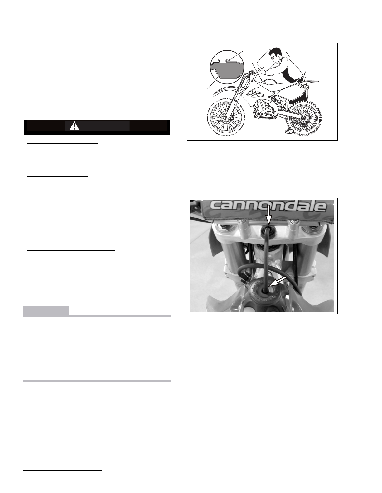
1. To remove and clean the steering head filter, first
remove the f ront number plate.
X440s Owner's Manual.fm
© 2001 Cannondale Corporation - All Rights Reserved
36
Page 38

2. Remove the bolt, washer , and filter assembly from the
steering head.
the element a few times to ensure even distribution of
the oil.
9. Carefully install the main air filter element onto the
cage.
1
2
1. Bolt and washer
2. Steering head filter
3. Separate the filter foam element from the cage.
2
10. Apply a thin layer of a high-quality waterproof grease
to the air filter mounting surface to help eliminate air
leakage.
1
11. Install the filter over the steering head opening.
12. Install the steering head filter bolt and washer.
TORQUE : Air, steering head filter, bolt
5.0 lbf•ft (6.8 N•m)
1. Foam element
2. Cage
4. To clean, spray a non-flammable or high-flash point
air filter specific cleaning solvent over the inside and
outside of the filter element and cage. Do NOT use
gasoline!
5. Allow it to soak then squeeze it a few times until all
the dirt has come off. Repeat if heavily soiled.
6. Rinse the filter with warm water and squeeze out
excess water.
CAUTION
Do not wring or twist the air filter.
7. Inspect steering head filter foam eleme nt and ca ge for
any damage. Replace ne w if damaged.
8. Apply a light, even coat of high-quality foam air-filter
oil over bo th sides of the a ir filter elem ent. Squeeze
37
P/N 951-05002032
Printed : 8/13/01
Page 39

FUEL
THROTTLE FREEPLAY
the throttle tube and c abl e; making su re it is pro perl y ro ute d.
If the throttle grip still does not operate properly, contact an
authorized Cannondale motorsports dealer for servicing.
To measure the freeplay, gently rotate the throttle grip until
the slack is ta ke n up , th en mea s ure ho w far th e gr i p move d .
If the measurement (a) is out of specification, adjustments
can be made at either the throttle grip or at the engine side
of the throttle cable
SERVICE : Fuel, throttle, freeplay
0.07-0.15 inches (2-4 mm)
WARNING
POTENTIAL HAZARD
Damaged throttle (e.g., sticking, cable frayed, or
improper freeplay)
WHAT CAN HAPPEN
While riding you could lose the ability to accelerate
or decelerate the engine with a subsequent loss of
vehicle control resulting in an accident where you
could be seriously injured or killed.
HOW TO AVOID THE HAZARD
Check the throttle for proper operation before each
ride. Make sure the throttle has the specified
freeplay.
If the throttle sticks open, immediately push and
hold down the stop button until the engine shuts off.
To check operation, with vehicle off, rotate the throttle grip
and make sure it moves e asi ly from fully closed to fully open
with the front wheel turned in all steering positions. The
throttle grip should return automatically from fully open to
fully closed when released.
If the throttle grip sticks, it is probably due to a cable
problem. Remove and lubricate the throttle cable, remove
and clean the throttle tube, and adjust the freeplay. Install
a
a. Throttle cable freeplay
ADJUSTING THROTTLE FREEPLAY (AT THE HANDLEBARS)
1. Pull the long rubber boot (1) down the throttle ca bl e so
the lockring (2) and throttle c abl e adju ster (3) are
visible.
2. Turn the lockring, using pliers, in direction (a) to
loosen it. Turn the adjuster in direction (a) to reduce
freeplay or direction (b) to increase freeplay. Tighten
the lockring secu rely.
2
1
3
a
X440s Owner's Manual.fm
© 2001 Cannondale Corporation - All Rights Reserved
b
1. Long rubber boot
2. Lockring
3. Cable adjuster
a. Loosen/decrease freeplay
b. Increase freeplay
3. If the throttle can not be adjusted further and the
freeplay is still out of specification, the cable will have
to be adjusted at the engine side.
38
Page 40

ADJUSTING THROTTLE FREEPLAY AT THE THROTTLE BODY
WARNING
POTENTIAL HAZARD
Crash resulting from a stuck throttle.
WHAT CAN HAPPEN
If the throttle cable locknut at the engine side of the
cable is not tightened securely the nu,t can loosen
and the cable can become dislodged. This could
result in a loss of engine throttle control and you
could be severely injured or killed in an accident.
HOW TO AVOID THE HAZARD
When adjusting throttle cable freeplay at the throttle
body side of the cable, make sure locknut is
tightened securely.
1. Adjust for maximum freeplay at the lever on the
handlebar.
2. Remo ve the front f ender, left ra diator s hroud and the
radiator guard.
3. Remove the upper radiator bolts and carefully move
the radiator forward.
4. Remove the upper, center, and lower bolts. Then
move the left frame rail so the throttle cable is
accessible.
CAUTION
Make sure the engine is properly supported to
relieve any undue stress after the left fram e rail bolts
are removed.
1
2
3
4
1. Upper bolt
2. Center bolt
3. Lower bolts
4. Left frame rail
5. Loosen the locknut. Turn the throttle cable adjuster in
direction (a) to increase freeplay or direction (b) to
reduce freeplay.
39
a
1
b
2
1. Locknut
2. Adjuster
a. Increases freeplay
b. Decreases freep lay
P/N 951-05002032
Printed : 8/13/01
Page 41

6. Tighten the locknut securely and install the left frame
rail. Tighten the rail bolts to the specified torque.
TORQUE : Frame, left frame rail upper bolt
25.0 lbf•ft (34.0 N•m)
TORQUE : Frame, left frame rail center bolt
35.0 lbf•ft 47.5 N•m)
TORQUE : Frame , left frame rail lower bolt
20 lbf•ft (27.0 N•m)
TORQUE : Coolant, upper radiator mounting bolt
5.0 lbf•ft (6.8 N•m)
7. Install the radiator and tighten the upper bolts to the
specified torque.
8. Install the radiator guard, left radiator shroud, and
front fender.
IDLE SPEED ADJUSTMENT
It is necessary to periodically adjust the idle speed for
optimum fuel efficie nc y and proper engine operation.
WARNING
POTENTIAL HAZARD
Severe burns to your hands or fingers.
WHAT CAN HAPPEN
The engine operates at e xt remel y high temperatu res.
If you touch the engine or surfaces around it, you
can be severely burned.
HOW TO AVOID THE HAZARD
1. Use extra caution when adjusting the idle speed.
2. Have an authorized Cannondale Motorsports
dealer adjust the idle speed.
CAUTION
The lower right radiator shroud bolt is supporting
the radiator (along with the coolant hoses), so do
not swing the radiat or out too far.
1. Allow the engine to reach operating te mp era ture 158°F
(70°C).
2. To achieve the smoothest idle speed, turn the idle
speed adjuster (1) in direction (a) to increase idle
speed or in direction (b) to decrea se id le speed.
a. Increase
b. Decrease
X440s Owner's Manual.fm
© 2001 Cannondale Corporation - All Rights Reserved
40
Page 42

FUEL TANK
WARNING
POTENTIAL HAZARD
Explosion or fire.
WHAT CAN HAPPEN
Gasoline is highly-flammable and an explosion can
occur if handled improperly or in areas where an
accidental spark or flame could ignite the gasoline.
You can be burned severely of even be killed if you
ignore this warning
HOW TO AVOID THE HAZARD
Always make sure the work area is free of possible
ignition sources (e.g., sparks, cigarettes, welders,
grinders, flames)
CAUTION
Press in the quick connect fitting tabs before reinstalling the quick connect hose fitting, or the Oringof the fittings can be damaged ( i.e., ripped, torn,
or dislodged).
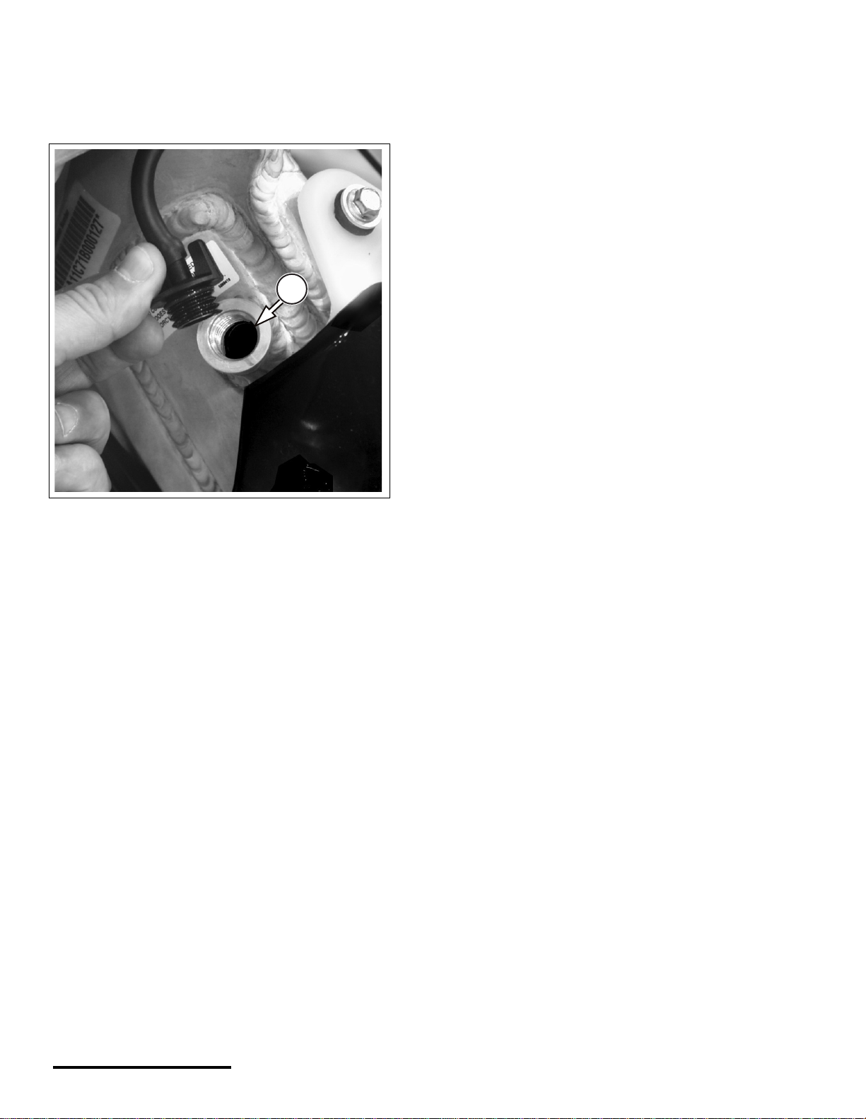
3. Disconnect the fuel tank quick connect outlet (1)
located on the left side of the fuel tank by pressing on
connector tabs and carefully withdrawing the hose
fitting.
1
a
1. Fuel tank outlet (quick connect)
a. Tab
Always inspect the condition of the O-rings before
re-installing and replace if they are torn.
Apply a light coat of engine oil to thequick connect
fitting O-rings before re-stalling into the tank.
LUBRICATE
O-RING
BEFORE
INSERTING
4. Disconnect the fuel return quick connect located on
the right side of the fuel tank .
a
1
1. Fuel tank return (quick connect)
a. Tab
1. Remove the side number panels, seat and radiator
shrouds.
2. Remove the fuse (located under the se at).
41
P/N 951-05002032
Printed : 8/13/01
Page 43

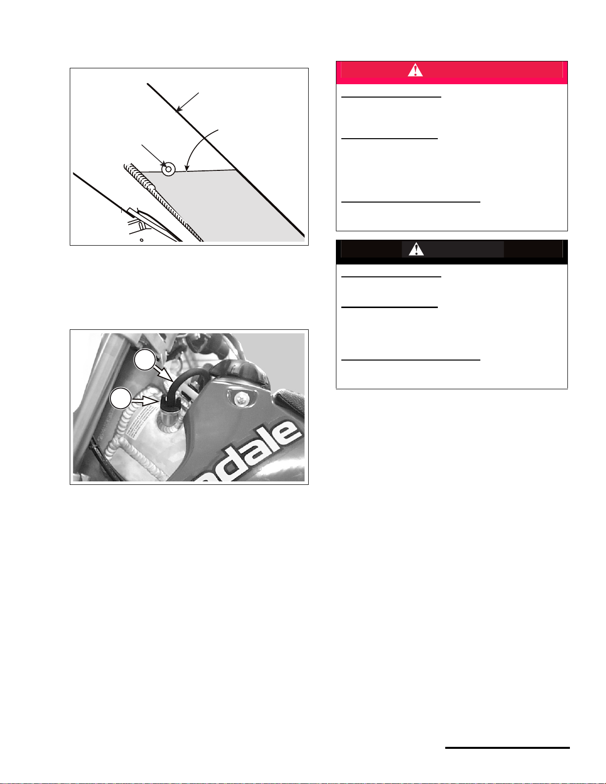
5. Remove the fuel tank bolt and lift up the front of the
FLOW
fuel tank. Slide the tank forward slightly, and remove
it from the vehicle.
1
1. Fuel tank bolt
6. To install the fuel tank, align the tank onto the frame.
NOTE : Make sure the fuel tank buffers (1) align with the
notches (a) on both sides of the fuel tank.
REPLACING THE FUEL FILTER
NOTE : Accumulation of dirt in the fuel filter will restrict fuel
flow. Proper fuel flow and pressure is critical to the reliability
of the fuel injection system and level of vehicle performance.
Therefore, the fuel filter should be inspected frequently and
replaced if necessary.
1. Remove the tank outlet quick connect fitting. Press in
on the fitting tab before remov ing the fitting from the
tank valve.
2. Loosen the filter hose clamps and remove the filter.
3. Reinstall a new filter and make sure the hose clamps
are tightened securely. Be sure to observe any flow
indicator on the filter housing.
1
a
1
1. buffer
a. notch
7. Tighten the bolt to the specified torque
TORQUE : Fuel, fuel tank mounting bolt
5.0 lbf•ft (6.8 N•m)
8. Press in the quick connect tabs on the fuel valves.
FLOW
2
1. Outlet quick connect
2. Fuel filter
9. Apply a light coat of engine oil to the outlet O-rings.
Then, return the quick connects, and install them into
the fuel tank valves.
X440s Owner's Manual.fm
© 2001 Cannondale Corporation - All Rights Reserved
42
Page 44

4. Tighten the lo ck nut to the specified torque.
BRAKES
For safe motorcycle operation it is critical to have the brake
system performing at its best. Regular inspection of the
brake components and brake fluid level should become a
habit prior to riding the motorcycle.
FRONT BRAKE FREEPLAY ADJUSTMENT
1. Gently pull in the brake lever until the play is taken up,
then measure the freeplay (a) at the end of the brake
lever. Adjust if out of specification.
TORQUE : Brake, lever adjuster, front, locknut
4.3 lbf•ft (5.8 N•m)
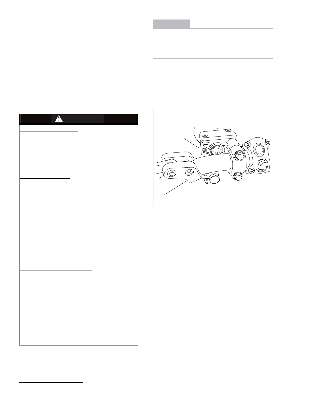
FRONT BRAKE LEVER POSITION
The position of the brake lever can be adjusted so that
control is comfortable when seated and standing.
1. Loosen the bolts (1).
2. Rotate the brake lever to the desired position and
tighten the clamp bolts to the specified torque.
Tighten the top bo lt firs t, then the lowe r bolt.
TORQUE : Brake, front, master cylinder mounting bolts
5.0 lbf•ft (6.8 N•m)
TORQUE
UPPER
BOLT FIRST
1
a
a. Freeplay
SERVICE : Brake, lever, front, freeplay, maximum
0.8 inches (20 mm)
2.
To adjust, loosen the locknut (1).
3. Turn the brake lever adjuster (2) in direction (a)
decrease freeplay, in direction (b) to increase
freeplay,
a
b
a
b
2
1
1
1. Front brake master cylinder mounting bolts
1. Locknut
2. Brake lever adjuster
a. Decrease freeplay
b. Increase f reeplay
43
P/N 951-05002032
Printed : 8/13/01
Page 45

FRONT BRAKE PADS INSPECTION
a
b
1
2
Worn brake pads can damage the brake disc, adversely
affecting brake performance and possibly causing an
accident. Never ride the motorcycle with worn or damaged
brake pads.
Each brake pad has wear indicator marks (1) and grooves
(2). If either brake pad is worn to the minimum thickness
indicator (3) or beyond the minimum thi ckness (a), the brake
pads need to be replaced with a new set.
Contact an authorized Cannondale Motorsports delaer for
replacement.
a
1
a
2
3
3. Turning the hex in direction (a) will lower the brake
pedal and turning the hex in direction (b) will raise the
pedal.
1. Locknut
2. Hex
a. Lowers the brake pedal
a. Raises the brake pedal
1. Wear indicator marks
2. Minimum thickness indicator
3. Wear indicator grooves
a. Minimum thickness
SERVICE : Brake, pad thickness, front, minimum
0.04 inches (1.0 mm)
REAR BRAKE PEDAL HEIGHT ADJUSTMENT
The rear brake pedal height can be adjusted for comfort as
well as proper operation.
1. To adjust, loosen the locknut on the master cylinder
pushrod.
2. Turn the hex on top of the pushrod until the brake
pedal is at the correct height.
4. Tighten the lo ck nut to the specified torque.
TORQUE : Brake, rear brake m aster cylinder pushrod,
locknut
13.0 lbf•ft (17.6 N•m)
X440s Owner's Manual.fm
© 2001 Cannondale Corporation - All Rights Reserved
44
Page 46

When adjusting the brake pedal, make sure that clearance
Check brake operation be fore riding the motorcycle. Failu re to follow this warning can lead to a serio us accident with subsequen t serious injury or death.
(a) between the lower end of the pushrod (1) and the brake
pedal is within specification.
When raising the br ak e p eda l (2 ), do not allow the lower end
of the pushrod thread (3) to enter into the brake pedal joint
(4).
1
a
4
2
1. Pushrod lower end
2. Brake pedal
3. Pushrod thread
4. Brake pedal joint
a. Clearance
SERVICE : Brake, rear, master cylinder pushrod,
clearance
0.04 in (1mm)
REAR BRAKE PADS INSPECTION
Each brake pad has wear indicator grooves (1). If either
brake pad is worn to the minimum thickness indicator (2) (or
beyond the minimum thickness (a)), the brake pads need to
be replaced with new ones as a set. Contact an authorized
Cannondale Motorsports dealer for replacement.
1
a
CHECK BOTH
PADS!
1. Wear limit indicators
a. Minimum thickness
SERVICE : Brake, pad thickness, rear, minimum
0.04 inches (1.0 mm)
45
P/N 951-05002032
Printed : 8/13/01
Page 47

EXHAUST
The primary functions of the exhaust system are to deliver
the burned combustion gases to the atmosphere, reduce
exhaust noise to an acceptable level, and to route the
exhaust gases away from the rider.
INSPECTING THE EXHAUST SYSTEM
Inspect the exhaust pipe and silencer for cracks, dents, rust
or other damage. If any damage is found, contact an
authorized Cannondale dealer for servicing.
NOTE : The exhaust system is shown removed from the
vehicle for clarity.
TORQUE : Exhaust pipe bolt
5.0 lbf-ft (6.8 N•m)
TORQUE : Silencer mounting bolt
15.0 lbf-ft (20.3 N•m)
X440s Owner's Manual.fm
© 2001 Cannondale Corporation - All Rights Reserved
46
Page 48

CLUTCH LEVER FREEPLAY
CLUTCH
CLUTCH LEVER POSITION
The clutch lever position can be adjusted so it can be used
comfortably while sitting or standing.
1. Loosen the clutch lever clamp bol ts (1).
1
1
1. Clutch lever clamp bolts
SERVICE : Clutch, lever, freeplay
0.08 - 0.16 inches (2 - 4 mm)
a
TAKE UP
SLACK
IN CABLE
a. Clutch lever freeplay
CAUTION
Check the clutch actuating arm position following
any adjustment to the lever.
2. Rotate the clutch lever to the desired position and
tighten the clamp bolts to the specif ied torque.
3. Tighten the upper clamp bolt first, then the lower
clamp bolt.
TORQUE : Clutch, lever clamp, bolts
5.0 lbf•ft (6.8 N•m)
NOTE : Adjust clutch lever freeplay at the lever first. If the
specified freeplay cannot be achieved, adjust for more
available freeplay at the inline adjuster.
LEVER
1. To adjust the lever, the quick adjuster until the specified
freeplay is reached.
a
1
1. Quick adjuster
a. Increases freeplay
47
P/N 951-05002032
Printed : 8/13/01
Page 49

THE INLINE CABLE ADJUSTER
CLUTCH ACTUATING ARM ADJUSTMENT
To increase available freeplay at the lever, loosen locknut
and turn the adjuster clockwise.
To decrease available freeplay at the lever, loosen the
locknut and turn the inline ad jus ter co unt ercl oc kw i se .
Re-adjust freeplay at the lever.
Tighten the locknut securely after adjusting the clutch cable.
2
1
NOTE : A special tool to hold the release collar has been
developed for this procedure, but right angle circlip pliers of
the correct size will work. For information on special tools
developed to service your model, contact an authorized
Cannondale dealer.
There is no need to drain transmission fluid to perform the
following procedure. But, be su re to avoid co ntaminating the
transmission oil when the clutch cover is removed. Also,
make sure the cover seal is in good condition. Replace it
with a new one if it is damaged .
1. Place the vehicle on a stand.
2. Adjust the clutch lever to its maximum freeplay.
3. Remove the shift lever and clutch cover.
4. Hold the release collar with the special tool ( or right
angle circlip pliers) and lo os en the adj us ter loc kn ut.
3
1. Locknut
2. Clutch cable adjuster
a. Decreases freeplay
b. I ncreases freeplay\
2
1
4
5
1. Locknut
2. Clutch release collar
3. Adjuster
4. T-handle (2.5mm allen)
5. Right angle circlip pliers
5. Have an assistant apply light pressure on the
actuating arm toward the cy linder head.
6. As your assistant is holding light pressure on the arm,
hold the release collar and turn the adjuster until the
X440s Owner's Manual.fm
© 2001 Cannondale Corporation - All Rights Reserved
48
Page 50

actuating arm is positioned according to the following
illustration.7
7. Tighten the adjuster locknut to the specified torque.
DRIVE
DRIVE CHAIN SLACK
SERVICE : Drive, chain, slack
2.2 - 2.4 inches (55 - 60 mm )
WARNING
POTENTIAL HAZARD
Drive chain is too tight or loose, sprocket teeth are
broken and/or wo rn, or chain and s procket is packed
with dirt.
8. Reinstall the clutch cover and shift lever.
TORQUE : Clutch, release collar locknut
3.3 lbf•ft (4.5 N•m)
TORQUE : Clutch, cover bolts
3.3 lbf•ft (4.5 N•m)
TORQUE : Transmission, shift lever pinch bolt
5.0 lbf•ft (6.8 N•m)
9. Now, adjust the clutch lever freeplay.
WHAT CAN HAPPEN
The vehicle’s handling and engine performance will
suffer which could cause the rider to lose control
and have an accident.
HOW TO AVOID THE HAZARD
Inspect and clean the drive chai n before each ride.
NOTE : Clean and lubricate the drive chain before
measuring the slack. The chain’s condition affects the
accuracy of your measurement. Also, when measuring,
rotate the chain and measure different links over the same
spot.
1. Place the vehicle on a stand so the rear wheel is of f the
ground.
2. Inspect the drive chain slack at a middle point
between the two sprockets. If the slack is out of
specification, adjust it.
a
49
a. Drive chain slack
3. To adjust the chain slack, straighten the cotter pin.
Remove and discard it.
P/N 951-05002032
Printed : 8/13/01
Page 51

4. Loosen the rear wheel axle nut (2) and the adjuster
bolt locknuts (3).
3
2
4
1
1. Cotter pin
2. Rear axle nut
3. Locknut
4. Adjuster bolt
6. Place a rag between the drive chai n and re ar sproc ket
then rotate the wheel backward to tighten the chain.
7. Tighten the rear wheel axle nut.
5. Increase or decrease slack by using the adjuster
bolts.
CAUTION
The alignment marks on the adjuster blocks a nd the
marks on the swingarm must be adjusted so they
are in the same position on each side of the swingarm.
Make sure the drive chain is straight and in-line with
the sprockets.
3
1
a
b
TORQUE : Wheels, rear axle, nut
72.0 lbf•ft (98.0 N•m)
8. Install a new cotter pin and properly bend the tabs
around the axle nut.
1
1. Cotter pin tabs
4
9. Tighten the dri ve chain adjuster locknuts securely.
10. Measure the drive chain freeplay again and adjust if
necessary.
NOTE : Make sure both adjuster blocks are in the same
position on each side of the swingarm.
2
1. Lock nut
2. Adjuster bolt
3. Adjuster block mark
4. Swingarm scale
a. Increase slack
b. Decrease slack
X440s Owner's Manual.fm
© 2001 Cannondale Corporation - All Rights Reserved
1 1. Check the rear wheel alignment.
12. Take the vehicle off the stand, roll it forward and
backward a few times and apply the rear brake. Make
sure the rear brake operates properly. The rear wheel
50
Page 52

rotates properly and the brake disc is not rubbing
against the brake pads.
DRIVE CHAIN STRETCH LIMIT
SERVICE : Drive, chain, length (stretch), maximum (see
specification for ex act pin count)
6.0 inches (151 mm)
INSPECTING THE MASTER LINK CLIP.I
WARNING
POTENTIAL HAZARD
Breaking the drive chain.
WHAT CAN HAPPEN
If the master link clip is installed incorrect ly it can be
dislodged allowing the chain to break. This will
cause you to lose control. You can be seriously
injured or killed.
HOW TO AVOID THE HAZARD
Anytime the drive chain is serviced make sure the
drive chain clip is completely installed in its groove
and that the open end of the clip faces opposite the
chain rotation. Make sure the master link clip is
completely installed in its groove .
b
Place the vehicle on a stand so the rear wheel is off the
ground.
Measure the distance (a) from pin center to pin center
across the specified pin count. If the measurement is out of
specification, replace the drive chain with a new one.
a
a. Measurement
a
1. Clip
a. Open end
b. Direction of chain rotation
1
51
P/N 951-05002032
Printed : 8/13/01
Page 53

INSPECTING/REPLACING THE SWINGARM BUFFER
SERVICE : Drive, swingarm buffer, thickness, standard
0.4 inches (10 mm)
SERVICE : Drive, swingarm buffer, thickness, minimum
0.1 inches (3 mm)
DRIVE CHAIN GUIDE AND BLOCK
SERVICE : Drive, chai n guid e b lo ck, thickness, standard
0.5 inches (12 mm)
SERVICE : Drive, chain guide block, thickness,
minimum
0.1 inches (3 mm)
NOTE : Be sure to inspect the thickness of the buffer at a
few different points of its entire length. Wear may not be
uniform. If out of specification at any point, replace it with a
new one.
1. Inspect the swingarm buffer for cracks, wear, or other
damage. Replace the swingarm buffer with a new one
if it is damaged or the wear (a) is out of specification.
1
a
Inspect the drive chain guide and drive chain guide block for
cracks, wear, or other damage. Replace the drive chain
guide block with a new one if it is damage d or the wear (a) is
out of specification.
a
1
2
1. Drive chain guide
2. Drive chain guide block
a. Maximum wear
Check the drive chain guide bolts and tighten to the
specified torque if necessary.
TORQUE : Drive, chain guide, mounting bolts
9 lbf•ft (12.2 N•m)
1. Swingarm buffer
a. Thickness
2. To replace, place the vehicle on a suitable stand.
3. Remove the bolts and the old buffer. Make sure you
clean the buffer moun tin g scr ews with contact cleaner
and apply Loctite #2 42 agen t befor e insta lling the new
buffer.
4. Install the new buffer and tighten screws to specified
torque.
TORQUE : Drive, swingarm buffer, mounting screws
17.0 lbf•in (0.19 N•m)
X440s Owner's Manual.fm
© 2001 Cannondale Corporation - All Rights Reserved
52
Page 54

DRIVE CHAIN ROLLERS
a
CHECKING THE REAR END
SERVICE : Drive, chain rollers, diameter, standard
1.4 inches (35.2 mm)
SERVICE : Drive, chain rollers diameter, minimum
1.3 inches (32 mm)
Inspect the upper and lower drive chain rollers for cracks,
wear, or other damage. Replace the drive chain roller with a
new one if the outside diameter (a) is out of specification.
a
1
1. Upper drive chain roller
a. Outside diameter
Before every ride, check the rear end for worn or loose
swingarm bearings.
WARNING
POTENTIAL HAZARD
Riding this vehicle with worn or loose swingarm
bearings
WHAT CAN HAPPEN
You can lose control of the vehicle resulting in
serious injury or death.
HOW TO AVOID THE HAZARD
Always check the condition of the swingarm
bearings before each ride.
Place the vehicle on a stand so the rear wheel is off the
ground.
Hold each side of the swingarm and try to move it from sideto-side. If any freeplay is felt, contact an authorized
Cannondale motorsports dealer for servicing.
1
1. Lower drive chain roller
a. Outside diameter
53
P/N 951-05002032
Printed : 8/13/01
Page 55

REMOVING AND RE-INSTALLING THE COUNTERSHAFT SPROCKET GUARD
COUNTERSHAFT SPROCKET REPLACEMENT
1. Place the motorcycle on a stand.
2. Remove the bolts and count ers haft sprocket guard.
2
1
1. Bolts
2. Countershaft sprocket guard
1
Engine was removed on photos of the following procedure.
Follow same steps for an installed engine.
1. If removed, apply assembly lube to the countershaft
sprocket spacer and to the lips of the seal. Install the
spacer so that the internal o-ring faces inward.
2
1
2
1. Larger end
2. Smaller end
This photo shows the correct installation of the chain guide
plate mounted directly behind the countershaft sprocket
guard. Notice the shape and orientation of the guide. It is
being held here but would normally be installed t ogether with
the guard.
3. Installation is reverse order of removal.
1. Countershaft spacer
2. O-ring
2. Install the countershaft sprocket, the splined lock
washer , an d c ou nte rsha ft sprocket nut with the reces s
(a) of the nut facing inward toward the sprocket.
1
2
3
a
TORQUE : Drive, counter shaft sprocket guard bolts
5.0 lbf•ft (6.8 N•m)
X440s Owner's Manual.fm
© 2001 Cannondale Corporation - All Rights Reserved
1. Sprocket
2. Splined lock washer
3. Nut
a. Recess
54
Page 56

3. Use a sprocket wrench to hold the sprocket and
tighten the nut to the specified torque .
SPROCKET INSPECTION
NOTE : Replace both the sp rockets a nd drive cha in as a set
1
2
a
TORQUE : Transmission, countershaft sprocket nut
29.5 lbf•ft (40.0 N•m)
4. Bend the splined lock washer over the nu t.
Inspect the sprockets for cracks, chipped or broken teeth,
excessive wear, or other damage. Check the countershaft
3
sprocket nut and tight en if nece ss ary.
2
3
1
1. Normal teeth
2. Worn teeth
3. Damaged teeth
1
2
3
a
55
P/N 951-05002032
Printed : 8/13/01
Page 57

ELECTRICAL
5. Whenever a connector or coupler is disconnected or
checked, be sure to clean it and apply some dielectric
grease before reconnecting.
CLEANING CONNECTORS
SYSTEM SERV ICING
Many electrical problems are caused by faulty electrical
connectors or couplers. For example, wet terminals/pins,
dirty or corroded terminals/pins, or broken or bent cable pins
within multi-plug cou pl ers .
WARNING
POTENTIAL HAZARD
Damaged electrical system.
WHAT CAN HAPPEN
A damaged electrical system can cause a fire.
HOW TO AVOID THE HAZARD
Always disconnect the battery when working on an
electrical part on the vehicle. When reconnecting
the battery ALWAYS connect the positive (+) lead
first.
CONNECTORS AND COUPLERS
Within this manual “connectors” refer to a single male lead
that connects into a single female lead.
Couplers contain multi-pins and usually have some sort of
locking device (e.g., barb, hook, eye) which must be
released before the two halves can be separated. Both
couplers and connectors will be referred to as quickconnects.
Refer to the following tips w he n dis co nnecting or connecting
electrical connectors or couplers.
Wipe the connector or coupler with a clean, lint-free rag and
blow off any moisture using compressed air. Remove
corrosion, rust, stains or other forei gn m ater ial us in g contact
cleaner on terminals and a water-displacement chemical on
connector seals. Apply a light coat of dielectric grease onto
the terminals/pins an d pr ope rly connect the halves.
ENGINE MANAGEMENT SYSTEM
All Cannondale models use advanced fuel injection
systems. Engine operation is supported by an Engine
Management System (EMS) which controls both ignition
and fuel delivery.
The engine management system consists of three types of
electrical components: an Engine Control Module (ECM),
sensors, and actuators.
• The engine control module (ECM or ECU) precisely
calculates ignition timing a nd fueling delivery f or all
engine speeds and loads (based on the currently
installed ECM mapping). The ECM is an extremely
reliable component and should be the last
component checked in the event there is a problem
with the fuel injection system.
• Sensors collect engine operating information and
transmit it to the ECU.
• Actuators are devices like the fuel injectors, fuel
pump, fuel pressure regulator, spark plug coil, and
relays.
IGNITION TIMING
1. When disconnecting a con ne cto r, be sure to hold the
coupler/connect ors; do not pull the leads.
2. Always check for a locking device which must be
released before the coupler can be separated. Also,
be sure to hold both halves of the coupler; do no t pull
the leads.
3. Inspect couplers for bent terminals/pins, damaged
cable terminal/pin joints, water, dirt, or corrosion, and
secure wiring. If a terminal or pin is bent, carefully
straighten it with a thin-blade screwdriver.
4. When connecting a connector or coupler, make sure
there is no dirt present. Be sure to push the male and
female ends together squarely to ensure that the
terminals/pins do not get bent or incorrectly located.
And most importantly, make sure the two halves
connect positively.
X440s Owner's Manual.fm
© 2001 Cannondale Corporation - All Rights Reserved
Ignition timing is continuously changed based on rpm and
engine load conditons determined by the ECM and the
installed map(s). The ignition system is a constant energy
type ignition with 12 V primary and approximately 10,00020,000 V secondary.
• Igntion timing is controlled by the ECM and is not
user adjustable.
• Ignition dwell time is controlled by the ECM and is
not user adjustable.
Timing is accomplished by the crankshaft position sensor
which is located in the generator housing. The wide tooth/
wide space pattern on th e fly w hee l pas se s und er the sens or
near bottom dead center (BDC).
56
Page 58

CAUTION
MC1000 DIAGNOSTICS
Do not attempt to advance or retard the ignition timing by moving the crankshaft position sensor. The
fuel injection and ignition timing have been tuned to
produce maximum engine power at all speeds and
throttle positions. Deviation from factory ignition
timing can cause serio us e ngine da mage. T he crank shaft position sensor monitors engine position at
BDC, not TDC. Therefore, ignition timing is based off
of BDC, not TDC.
Engine Control Module (ECM)
M1000
The ECM is located on the ECM mounting plate within the
subframe. ECM diagnostics are performed by using
specially developed Windows based software and a data
cable.
A software diagnostic program has been developed to
service this vehicle . It is a Win do ws base d program that ca n
be used on a PC or Palm PC. A special data cable is used
to connect the vehicle to the PC or Palm PC.
Contact an authorized Cannondale motorsports dealer for
special tools developed to service your vehicle.
2
1
Components have been removed for this photo.
1. Data port
2. Data port
Components have bee n remo ved for this photo.
57
P/N 951-05002032
Printed : 8/13/01
Page 59

ECM HARNESS CONNECTOR(S)
The ECM harness connector is a “locking type.” Tests
involving fault code diagnostics require the placing of test
leads to specific pin locations of the connector.
SENSORS
CRANKSHAFT POSITON SENSOR
NOTE : If the crankshaft position sensor fails, the
motorcycle will not run.
The crankshaft position sensor is located in the generator
housing. This sensor detects movement of a toothed wheel
that is molded into the flywheel and attached to the right
side of the crankshaft. The wheel has a 36-tooth pattern.
The teeth are evenl y spa ce d w i th th e exception of one triple
length tooth next to one triple length gap.
Everytime this tooth/gap passes the sensor the ECM
interprets it as bottom dead center (BDC). The ECM uses
this information to determine engine speed and crankshaft
position in relation to the point where fuel is injected and
ignition of the air/fuel mixture occurs.
as a base. Throttle-plate angle is used by the ECM to
determine fueling requirements for all throttle positions. The
signals that the TPS sends, informs the ECM of not only the
position of the throttle plate, but the speed with which it is
being opened or closed. The engine load is determin ed from
the TPS and engine speed (rpm).
The voltage output from the TPS increases proportionately
as the throttle is opened .
Components have been removed for this photo.
The flywheel cover has been removed for this photo to
show the sensor tip.
THROTTLE POSITION SENSOR (TPS)
The TPS is a small, black plastic sensor attached to the
throttle plate shaft and located on the right side of the
throttle body. The TPS is a potentiometer that gives a
reading in the fully-close d position an d all other thr ottl e-plate
opening angles a re c alc ul ate d us ing the fully-closed posit ion
IDLE AIR CONTROL VALVE (MC1000)
The idle air control valve is mounted on the front of the
throttle body and permits air flow to bypass the throttle
plate. The valve is controlled by the ECU.
Components have been removed for this photo.
X440s Owner's Manual.fm
© 2001 Cannondale Corporation - All Rights Reserved
58
Page 60

COOLANT TEMPERATURE SENSOR
The engine temperature sensor is brown, located on the
front of the cylinder head, and is an NTC thermistor. The
ECM receives electronic signals from this thermistor and
uses them to determine the coolant temperature. This
information is used by the ECM to optimize fueling at all
engine temperatures and to calculate hot and cold start
fueling requirements.
The engine temperature sensor's resistance decreases as
the temperature increases.
inducted air (and therefore the amount of oxygen available
to ignit e the fuel), altering the effective engine load and thus
the fuel required for proper combustion.
The ECM uses information from this sensor to compensate
for changes in air temperature by adjusting the amount of
injected fuel to a level which enables clean combustion
(reducing the risk of knock caused by high air intake
temperatures) and low emissions.
Components have bee n remo ved for this photo.
AIR TEMPERATURE SENSOR
The intake air temperature sensor is green, located on the
front area of the airbox. It is a NTC thermistor that gives an
indication of the temperature of the air that will be inducted
into the engine. An intake air temperature sensor is installed
because the air temperature affects the density of the
BAROMETRIC PRESSURE SENSOR
NOTE : The barometric pressure sensor is intergrated
inside the ECU.
The intake air pre ssure (bar ometric) sensor is built i nto the
ECM and is connected to the airbox plenum by a narrow
tube. The sensor measures the air pressure in the airbox.
Using this information the ECM determines the air density,
and when added to oth er inpu ts to the ECM, the engine load
is calculated. This information is then used to adjust the
amount of injected fue l to matc h the pr ev ail ing c ond itions.
59
P/N 951-05002032
Printed : 8/13/01
Page 61

FUEL INJECTORS (LEFT AND RIGHT)
The fuel injectors are located in the throttle body and are
positioned as close as possible to the back of the intake
valves. The spray pattern and flow rate of the injectors are
fixed, but the length of time they remain open is variable.
The duration that the injec tors stay open is calculated by the
ECM using data received by the various sensors.
during the first three seconds ( e.g., fuel lines drained o r tank
empty). To activate the pressurizing cycle, moemtarily press
the start button without activating the starter motor.
OUTLET
INLET
2
1. Left fuel injector
2. Right fuel injector
1
FUEL PUMP
The fuel pump is located on the left side of the vehicle an d is
mounted on the engine rail. When the engine management
system is firs t “powered-up” (accomplished by pressing the
start button without running the starter motor) this pump
activates for 3 seconds to pressure the fuel system then
turns off again until the engine starts. When the engine
starts, it resumes pumping providing pressurized fuel to the
injectors. T he th ree secon d pres sur izi ng cy cle m ay have to
be repeated if the pump does not recieve adequate fuel
FUEL PRESSURE REGULATOR
The fuel pressure regulator is mounted on the right side of
the vehicle on the engine rail. This device maintains the
correct fuel pressure and returns fuel to the tank after it
passes the fuel injectors.
TO FUEL TANK
FROM RIGHT
FUEL INJECTOR
X440s Owner's Manual.fm
© 2001 Cannondale Corporation - All Rights Reserved
BAROMETRIC
PRESSURE HOSE
CONNECT
Components have been removed for this photo.
60
Page 62

SPARK PLUG CAP/COIL
BATTERY REMOVAL (MC1000)
The spark plug cap/coil is a “pencil-type” coil located on top
of the spark plug. The ECM controls when the coil is
switched on or off. The coil is switched on to allow sufficient
time for the coil to charge to a level where a spark can be
produced at the spark plug. The coil switches off at ignition,
which is timed for good engine performance.
Components have bee n remo ved for this photo.
BATTERY
To remove the battery :
Remove the side number panels, radiator shrouds, seat, ,
fuse, and fuel tank. Unbolt the MC1000 and lay it carefully
over the right side of the subframe. Be careful not to
disconnect the barometric sensor hose of the ECU or
damage the harness connectors. Disconnect the negative
lead of the battery first, then dis conne ct the p ositiv e (+) lead.
Be careful not to disconnect the barometric sensor hose of
the ECU or damage the harness connectors. Then, remove
the hold down strap and lift out the battery.
CHARGING THE BATTERY
WARNING
POTENTIAL HAZARD
Attempting to open the battery, remove the cap strip
or add fluids to this maintenance free battery.
WHAT CAN HAPPEN
If you pry off the cap strip on a maintenance free
battery, you could release poisonous gas and
corrosive fluid which could injure you severely.
HOW TO AVOID THE HAZARD
Never attempt to open the battery cap strip.
Keep sources of ignition away from the battery (e.g.
cigarettes, flames, or spar ks ).
The battery is mounted within the subframe. Cannondale
motorcycles are equipped with maintenance free type
batteries and do not require the addition of water. In fact, if
you try to open the battery you will damage it and exposed
yourself to harm.
The fuel injection system benefits most from a fully charged
battery. Weak batteries will cause hard starting and a
general reduction in ve hic le performance.
WARNING
POTENTIAL HAZARD
Battery explosion or electrical fire.
WHAT CAN HAPPEN
Failure to disconnect negative (-) battery lead first
can cause the battery to explode. This could result
in serious injury to anyone in the vicinity of the
battery.
HOW TO AVOID THE HAZARD
Always discon nec t the negative (-) battery lead first.
When reconnecting connect the negative lead last.
CAUTION
Never allow a battery to s t and in a discharged condition.
The battery capacity is sized for maximum performance and minimal weight. Repeated starting without running the engine long enough to replenish the
battery will result in a discharged battery with insufficient power to restart the engine.
Don’t charge the battery in your motorcycle with a
car-type battery charger - you will ruin it. Use a
motorcycle-type battery charger. Typically, these
types of chargers deliver a a much lower maximum
charging rate (2 amps).
1. Remove the battery.
2. Set the battery charger to 12 V.
3. Connect the red battery charger lead to the positive
(+) battery terminal and the black battery charger
lead to the negative (-) battery termin al.
61
NOTE : After charging the battery, mark the charging date
on the battery case.
P/N 951-05002032
Printed : 8/13/01
Page 63

NOTE : Do not overcha rge bat tery. Overcharging can cause
the volume of electrolyte to decrease reducing the
effectiveness and life of the battery.
FUSE
The fuse is located under the seat. If a fuse blows
repeatedly this could indicate a problem in the electrical
system. If this happens, consult an authorized Cannondale
motorsports dealer.
SERVICE : Electrical, fuse, rating
20A (amps)
FUSE REPLACEMENT
WARNING
POTENTIAL HAZARD
Using a fuse with a current rating other than
specified.
4. Inspect the fuse for a blown link or other damage.
WHAT CAN HAPPEN
An incorrect fuse may not provide protection to the
electrical system. An unprotected system can cause
an electrical fire which can lead to a serious
accident.
HOW TO AVOID THE HAZARD
Replace only with the spec ifie d fuse.
CAUTION
Do not pull on the leads when separating the bottom
from the top of the fuse holder.
1. Remove the seat.
2. Pull the catch up with your finger or a thin-blade
screwdriver.
3. Pull the bottom of the fuse holder towards the front of
the vehicle, and remove the fuse.
1. Fuse
2. Fuse holder bottom
1
1. Good fuse
2. Blown Fu s e
a. Fuse link
1
2
a
2
a
X440s Owner's Manual.fm
© 2001 Cannondale Corporation - All Rights Reserved
62
Page 64

SPARK PLUG
REMOVING THE SPARK PLUG
SERVICE : Electrical, spark plug, type
NGK (CR8EK)
SERVICE : Electrical, spark plug, gap
0.024 - 0.028 inches 0.6 - 0. 7 mm)
4. Disconnect the spark plug coil coupler (1) from the
coil.
CAUTION
Whenever the spark plug is removed from the cylinder head, cover the spark plug hole with a clean rag
to avoid dirt getting into the engine.
1. Remove the fuel tank. See “Fuel” in the Maintenance
and Adjustment section of this manual for how to
remove the fuel tank .
2. Remove the bolts (1) and move the main relay
mounting plate assembly (2), along with the wire
harness, away from the rear shock strut.
2
1
1
1. Spark plug coil coupler
5. Remove the bolt and spark plug coil holder.
2
1
1. Bolt
2. Spark plug coil holder
1. Bolts
2. Mounting plate
3. Remove the bolts, washers, and the rear shock strut .
NOTE : Keep your hand under the upper nut and washer
so they do not fall on top of the engine.
63
6. Remove any dirt from the cylinder head and the area
around the spark plug with compressed air.
7. Remove the spark pl ug coil.
8. Use a socket and long extension to loosen and
remove the spark plug.
P/N 951-05002032
Printed : 8/13/01
Page 65

INSPECTING THE SPARK PLUG
If in doubt concerning the condition of the spark plug,
consult an authorized Cannondale Motorsports dealer. The
simple answer is to replace an old spark pl ug with a new
one anytime you remove it, but since the spark plug is a
valuable indicator of engine operating characteristics it is
extremely i mp o rta n t to have it evalua ted by a skilled service
technician. Consult an authorized Cannondale motorsports
dealer.
The spark plug ga p (a ) must be m easured with a wire gauge
or feeler gauge. If the gap is out of specification, adjust it.
If the spark plug utilizes multiple ground electrodes,
measure each gap.
a
INSTALLING THE SPARK PLUG
CAUTION
Only install the spark plug into a cool engine.
Always use the specified spark plug with the proper
gap. Using an incorrect spark plug may cause
severe engine damage.
Incorrectly installing the spark plug can damage the
cylinder head. An overly-tight or cross-threaded
spark plug will damage the threads in the spa rk plug
hole
Make sure the specified gap is set and lightly coat the plug
threads with a suitable anti-seize compound; this will allow
for easier spark plug removal in the future.
Then, finger-tighten (a) the spark plug into its hole, and
tighten it to the specified torque (b).
a. Spark plug gap
a
b
a. Finger tighten
b. Tightening torque
TORQUE : Electrica l, spark plu g
8.9 lbf•ft (12.0 N•m)
TORQUE : Electrical, relay plate, mounting screws
3.3 lbf•ft (4.5 N•m)
TORQUE : Frame, rear shock strut, mounting bolts
25.0 lbf•ft (34.0 N•m)
X440s Owner's Manual.fm
© 2001 Cannondale Corporation - All Rights Reserved
64
Page 66

STEERING
2
4. Loosen the bolt (1) from each lower handlebar clamp
(2). Rotate the lower handlebar clamp 180° and
tighten the bolts to the specified torque.
ADJUSTING THE HANDLEBAR POSITION
The handlebar can be adjusted rearward from the factoryset position by removing the lower handlebar clamps and
rotating them 180°.
WARNING
POTENTIAL HAZARD
Handlebar clamp bolts not tightened to their
specified torque.
WHAT CAN HAPPEN
Handlebar may move or come off during operation.
Failure to follow these warnings can lead to an
accident resulting in severe injury or death.
HOW TO AVOID THE HAZARD
The lower handlebar clamps must be positioned
evenly so there is the same amount of space
between both the front and rear. And, they must be
tightened to the specified torque.
1. Place the vehicle on a stand and cover the gas tank
with a clean rag.
2. Remove the handlebar pad.
2
1
1. Bolts
2. Lower handlebar clamps
5. Place the handlebar onto the l ower hand lebar c lamps,
install the upper handlebar clamps, and tighten the
bolts to the specified torque
TORQUE : Steering, han dleb ar c la mp uppe r bolts
17.0 lbf•ft (23.0 N•m)
TORQUE : Steering, han dleb ar c la mp, lower bolts
60.0 lbf•ft (81.0 N•m)
After installing the handlebar, sit on the vehicle, apply the
front brake, and push down on the front end a few times to
check if the handleba r moves.
Also, turn the handlebar from lock-to-lock to check for
looseness or binding.
1
3. Remove the bolts from each upper handlebar clamp
(1). Then, remove the upper handlebar clamps and
lay the handlebar on top of the front number plate.
1
1
1. Upper handlebar clamp
65
P/N 951-05002032
Printed : 8/13/01
Page 67

SERVICE : Suspension, fork leg, grease (daily care)
Ohlins green grease - 148-01
SUSPENSION
FORK MAINTENANCE
Telescopic front forks depend on smooth friction free action.
Be certain to follow the maintenance recommendations in
the table below.
CAUTION
Do not use strong solvents (e.g., brake cleaner) to
clean the fork legs. Strong solvents will dry out the
fork seals and steel tubes, and cause friction and
leakage.)
Pre-Ride
Fork Leg Maintenance
1. Inspect for deep scratches, nicks,
or other damage.
2. Inspect the fork seals for cracks,
nicks, leaks, or other damage.
Also, check th e a r ea aro u nd and
below the fork seals for f ork flu id.
If there is any indication of
damage or leaks consult an
authorized Cannondale
motorsports dealer
3. Make sure the fork leg guards
are clean and not packed with
mud or dirt and the upper and
lower triple clamp pinch bolts are
tightened to the specifi ed torque.
4. After inspecting the fork legs,
apply a small amount of the
specified lubricant onto the fork
tubes. (Daily care)
5. Take the vehicle off the stand,
apply the front brake, and push
down on the handlebar several
times. This will allow the grease
to spread evenly over the fork
tubes and to allow you to check
for smooth and proper fork leg
operation.
1. Cle an externally wi th a light/mild
detergent and spray with an allpurpose oil after drying.
X440s Owner's Manual.fm
© 2001 Cannondale Corporation - All Rights Reserved
Post-Ride
(to be performed by
owner)
Every 25 Hours
(to be performed by
an authorized
Cannondale
motorsports dealer)
66
2. Check externally for leaks and
damage (e.g., nicks, dent).
3. Apply a small amount of the
specified grease onto the inner
tube and work it in by pushing
the fork legs up and down.
4. Remove the bleed screw to
allow built up air pressure in
each fork leg to escape, and
then reinstall the screw.
1. Disassemble the fork legs and
inspect all parts for wear and
damage. Replace worn parts, Orings, seals, and other items
according to asse mb ly proc ed ure.
2. Change the fork oil.
Page 68

BLEEDING AIR FROM THE FRONT FORKS
Bleed any accumulated air using the bleed screw located on
top of each fork leg after every ride.
CAUTION
When removing the bleed screw, do not allow dirt or
debris to enter the opening. The smallest amount of
dirt can severely damage the forks.
Do not over-tighten the bleed screw.
1. Place the vehicle in a stand so that the front w heel is of f
the ground and the forks are fully extended.
2. Remove the bleed screw (1) and allow any
accumulated air to escape.
ADJUSTING THE FRONT & REAR SUSPENSION “CLICKERS” (FRONT OR REAR)
Your 2002 Cannondale motorcycle suspension valving
settings are provided by Pro-Action Suspension. The
production settings and adjustments are design for a wide
range of riders and terrain. However these settings may not
be optimum for your weight, skill level, or terrain. Please
contact Pro-Action’s authorized service ce nters for service
or re-valving needs. They have 27 authorized service
centers across the United States. Contact Pro-Action for
the one nearest you.
PRO-ACTION WORLD HEADQUARTERS LOCATIONS
East
Pro-Action Suspension
361 1 8th Avenue
Beaver Falls, PA 15010
PH: 724-846-9055
FX: 724-846-1629
Email: GQ@PROACTION.ATTBBS.COM
Website: www.pro-action.com
West
Pro-Action INC
12156 Severn Way
Riverside, CA 92503
PH: 909-280-9882
FX: 909-280-9886
Email: WESTCOASTHQ@AOL.COM
Website: www.pro-action.com
1. Bleed screw
3. Reinstall the bleed screw and tighten.
1
67
P/N 951-05002032
Printed : 8/13/01
Page 69

ADJUSTMENT TIPS
CAUTION
Using too much force when closing the adjusters
will destroy important sealing surfaces.
Do not turn the adjusters beyond the fully closed
position (fully seated) or the adjusters will be
severely damaged.
FORK COMPRESSION ADJUSTER
1. The front and rear suspension systems are factory preset, based on a average rider (weight & skill). Choice of
individual se ttings wi ll vary dependi ng on s kill a nd ridin g
style.
2. When making adjustments, make them one at a time
and in small steps.
3. The external adjusters have a normal right-hand
thread. As you turn the external adjusters, you will
hear them click. Each click identifies a setting.
4. To avoid turning the adjuster in the wrong direction,
always fully close the adjuster (turn it clockwise until it
seats), then turn it counterclockwise the required
number of clicks until the desired setting is reached.
5. Click position 0 (zero) is when the adjusters are
turned clockwise until they are fully closed (i.e., fully
seated). This is the hardest damping and should be
your starting point. Turn the adjuster
counterclockwise and listen for the clicks that identify
setting positions “1”, “2”, etc.
6. Turning the adjusters counterclockwise (more clicks
out) will gi ve less damping force.
b
1. Fork leg compression adjuster
a. More damping (stiffer)
b. Less damping (softer)
SERVICE : Suspension, front forks, compression
adjuster “clicks out from fully seated,”
standard, 12
SERVICE : Suspension, front forks, compression
adjuster “clicks out from fully seated,”
maximum, 30
a
FORK REBOUND ADJUSTER
a
b
7. Normally, the adjusters should not be adjusted more
than two clicks at a time and no t outs ide th e max imum
click range.
8. When you think you have made an improvement, go
back to what you started with and double check to be
sure an improvement was made. Also, pay attention
to changes in co nd itions (e.g., tires, air temperature).
9. In general, compression damping changes should be
used to influence the vehicle's stability and response,
while rebound damping changes should be used to
influence comfort and trac tion.
10. When you need more damping force, you should
mainly try to increase compression damping and use
as little rebound damping as possible. This will result
in a gain in comfort and handling performance.
X440s Owner's Manual.fm
© 2001 Cannondale Corporation - All Rights Reserved
1. Fork leg rebound a djuster
a. More damping (stiffer)
b. Less damping (softer)
SERVICE : Suspension, front forks, rebound adjuster
“clicks out from fully seated”, standard, 12
SERVICE : Suspension, front forks, rebound adjuster
“clicks out from fully seated”, maximum, 27
68
Page 70

REAR SHOCK REBOUND ADJUSTER
REAR SHOCK
CAUTION
Do not attempt to disassemble or servic e the front or
rear shock absorber.
REAR SHOCK COMPRESSION ADJUSTER
b
a
1
b
a
1. Rear shock rebound adjuster
a. More damping (stiffer)
b. Less damping (softer)
SERVICE : Suspension, rear shock rebound adjuster
“clicks out from fully seated,”, standard, 14
SERVICE : Suspension, rear shock rebound adjuster
“clicks out from fully seate d,” maximum, 32
1. Rear shock compression adjuster
a. More damping (stiffer)
b. Less damp ing (softer)
SERVICE : Suspension, rear shock compression
adjuster “clicks out from fully seated”,
standard, 18
SERVICE : Suspension, rear shock compression
adjuster “clicks out from fully seated,”
maximum, 32
69
P/N 951-05002032
Printed : 8/13/01
Page 71

REAR SPRING PRELOAD ADJUSTMENT
SERVICE : Suspension, rear shock spring, maximum
installed length (b), 220mm
CAUTION
When adjusting the preload, be sure not to adjust
the spring out of the minimum installed length. If the
spring is not compressed to its minimum installed
length, which is slightly shorter than its uninstalled
length - the suspension travel could allow the
uncompressed spring to become loose and “slap”
on the shock resulting in damage.
1
2
a
b
On the rear shock absorber the preload adjuster is the metal
notched ring on the shock body.
a
b
1
2
1. Rear shock spring preload adjuster
2. Lockring
3. Adjuster ring
a. More preload (stiffer)
b. Less preload (softer)
1. Lockring
2. Adjusting ring
a. Minimum installed length
b. Maxi mum installed length
SERVICE : Suspension, rear shock spring, uninstalled
length, 230mm
SERVICE : Suspension, rear shock spring, minimum
installed length (a), 228mm
RIDE HEIGHT
SERVICE : Suspension, front ride height, 95mm
SERVICE : Suspension, rear ride height, 95mm
SETTING THE FRONT RIDE HEIGHT
Ride height is the amount the suspension sags with the rider
on the bike in full riding gear.
X440s Owner's Manual.fm
© 2001 Cannondale Corporation - All Rights Reserved
70
Page 72

CAUTION
SETTING THE REAR RIDE HEIGHT
If the front ride height is out of the specified range,
the fork spring preload must be changed. Changing
the spring preload should be left to an authorized
Cannondale motorsports dealer.
1. Place on a stand and measure height (a) with no rider.
a
a. No rider
2. Remove stand and measure hei ght (b) with rider.
Ride height is the amount th e suspension sags with the rider
on the bike in full riding gear.
NOTE : Adjust if out of the specif ied rang e. To decrease the
ride height, increase the rear spring preload. To increase the
ride height, decrease the rear spring preload.
1. Place on a stand and measure height (a) with no ride r.
a
a. No rider
2. Remove stand and measure he igh t (b ) with rider.
b
b. Measurement with rider
3. Calculat e (a - b = ride height).
b
b. Measurement with rider
3. Calculate (a - b = ride height).
71
P/N 951-05002032
Printed : 8/13/01
Page 73

STATIC SAG
SERVICE : Suspension, front static sag, 25-35mm
SERVICE : Suspension, rear static sag, 25-35mm
NOTE : Measure from the axle to the same point on the
rear fender each time.
MEASURING THE FRONT STATIC SAG
Static sag is the amount the suspension sags without the
rider on the vehicle.
CAUTION
If the front static sag is out of the specified range,
the spring preload must be changed. Changing the
spring preload should be left to an authorized Cannondale motorsports dealer.
NOTE : Measure from the axle to the same point on the
upper triple clamp each time.
SETTING THE REAR STATIC SAG
1. Place on stand and measure (a) with no rider.
a
b
a - b = rear static sag
4. If the sag is out of the specified range. The rear spring
must be changed.
a
a. Measurement on stand
2. Remove stand and meas ure hei ght (b) wi th ride r.
b
b. Measurement without stand
3. Calculate (a - b = static sag).
X440s Owner's Manual.fm
© 2001 Cannondale Corporation - All Rights Reserved
72
Page 74

TIRES & WHEELS
CHECKING THE TIRE PRESSURE
Sufficient tire pressure is vital for safe and proper handling.
Overinflation may impair ride comfort and reduce the ground
contact of the tires.
Insufficient tire pre ss ure will res ul t in:
• Poor handling and may cause the motorcycle to
“wander.”
• Rapid tire wear.
• Increase fuel consumption,
• Inhibit performance
• Less control.
Use a gauge to measure the pressure in a cold tire.
Regulate the tire pressure before each ride.
SERVICE : Tires, rear, tire pressure
14 psi (96.5 kPa)
WARNING
POTENTIAL HAZARD
Operating this vehicle with improper tires, or with
improper or uneven tire pressure.
WHAT CAN HAPPEN
Use of improper tires on this vehicle, or operation
of this vehicle with improper or uneven tire
pressure, may cause loss of control, increasing
your risk of having an accident which could result
in severe injury or death.
HOW TO AVOID THE HAZARD
Always use the size and type tires specified in the
Owner’s Manual for this vehicle.
Always maintain proper tire pressure as described
in this Owner’s Manual.
INSPECTING THE TIRES
Inspect each tire for worn tread, cracks, or other damage. If
damaged, replace with new tires.
Check the valve stem for cracks or other damage. If
damage is found, replace with a new inner tube. A tilted tire
valve stem indicates that the tire has slipped out of position
and must be remounted pro perl y.
Make sure the tire valve locknut is secure and the rimlock
nut is tightened to its sp ec ified torque.
SERVICE : Tires, front, size
80/100x21
SERVIC E : Tires, r ear, size
110/90x19
SERVICE : Tires, front, tire cold pressure
14 psi (96.5 kPa)
NOTE : If the tire or inner tube needs to be replaced or
remounted, contact an authorized Cannondale dealer for
servicing.
TORQUE : Rimlock nut
9lbf-ft (12.2 N•m).
1
3
2
73
P/N 951-05002032
Printed : 8/13/01
Page 75

REAR WHEEL ALIGNMENT
The following procedure requires a special tool. Do not
attempt the following procedure if you do not have the tool
or the skills to perform the procedure as described; consult
an authorized Cannondale motorsports dealer.
WARNING
POTENTIAL HAZARD
Reusing a cotter pin.
WHAT CAN HAPPEN
The cotter pin can break which could allow the rear
wheel axle nut to come loose. This could cause a
loss of control resulting in serious injury or death.
HOW TO AVOID THE HAZARD
NEVER re-use a cotter pin. Always replace cotter
pins with new ones.
1. Place the vehicle on a stand.
2. Loosen the lockring (1) on the special tool. Install the
special tool so each spindle fits snug and flush into
the rear axle (2) and pivot shaft (3) on the right side of
the vehicle, then tighten the lockring.
3
2
1. Lockring
2. Rear axle
3. Pivot shaft
NOTE : Use the ri ght-side as a base an d then adjust the
left-side into alignment.
3. Remove the special tool and install it on the left side
of the vehicle. If the spindle does not fit snug and
flush into the rear axle and the pivot shaft on the left
side of the vehicle, the wheel is out of alignment and
needs to be adjusted.
4. Readjust the drive chain freeplay, measure the
freeplay, and check the wheel alignment again. After
the drive chain freeplay and wheel alignment are
correct, install a new cotter pin. Do not loosen the
lockring or move the spindles on the special tool. Only
adjust the position of the adjuster blocks in the
swingarm.
1
X440s Owner's Manual.fm
© 2001 Cannondale Corporation - All Rights Reserved
74
Page 76

NOTE : The frame and subframe are shown removed from
the vehicle for clarity.
FRAME, SUB-FRAME, SWINGARM
INSPECTIONS
WARNING
POTENTIAL HAZARD
Driving a vehicle with a cracked or damaged frame,
subframe or other components.
WHAT CAN HAPPEN
A complete frame failure could result leading to a
serious accident.
HOW TO AVOID THE HAZARD
Do not ride a motorcycle that has a cracked or
damaged frame.
The aluminum frame is heat treated. Do not weld,
drill, or modify the frame, subframe, or swingarm;
these modifications may weaken the component.
Inspect the swingarm for cracks, deep scratches, or other
damage. If any damage is found, contact an authorized
Cannondale motorsports dealer for servicing.
1
1. Swingarm
NOTE : The swingarm is shown removed from the vehicle
for clarity.
Inspect the frame (1), lower frame rails (2) and subframe (3)
for cracks, deep scratches, or other damage. If any damage
is found, contact an authorized Cannondale motorsports
dealer for servicing.
1
3
2
1. Frame
2. Lower frame rails
3. Subframe
75
P/N 951-05002032
Printed : 8/13/01
Page 77

Throttle lubrication
LUBRICATION
Lubricate the points shown in the illustrations in accordance
with the maintena nce sc hedule or after the vehicle has b een
washed or operated i n wet , dusty, or rainy conditions. Before
lubricating each point, make sure it is clean and free of any
grease, rust, dirt, or grime.
1
7
4
6
2
NOTE : If the throttle does not operate properly the cable
may have been installed incorrectly. Remove the throttle
cable and make sure it is installed properly.
1. Place the vehicle on a stand.
2. Remove the engine start switch (1) screws and
separate the engine start switch housing.
1
1. Engine start switch
3. Remove the engine start switch from the handlebar.
The engine start switch can just hang freely or can be
zip-tied to the handlebar; away from the throttle area.
5
4
3
1. Clutch lever & cable
2. Throttle lever & cable
3. Drive chain
4. Footpeg pivot
5. Rear brake pedal pivot
6. Shift lever folding tip pivot
7. Kick stand pivot
After the vehicle is thoroughly dry, lubricate the controls as
described in this manual and coat any unprotected areas
with a water-displacement chemical.
Start the engine and let it run until the radiator is slightly
warm and then turn it off.
NOTE : Before riding the vehicle, it is recommended to go
over the entire vehicle and check for any damage or loose
fasteners.
4. Pull the long rubber boot (1) down the throttle cable
so the locknut (2) and throttle cable adjuster (3) are
visible.
5. Turn the locknut using pliers, in direction (a). Turn the
adjuster in direction (a) to slacken the throttle cable.
2
1
1. Long rubber boot
2. Locknut
3. Cable adjuster
a. Loosening direction
6. Pull the large rubber boot (1) over the throttle cable
housing and past the locknut and adjuster.
3
a
X440s Owner's Manual.fm
© 2001 Cannondale Corporation - All Rights Reserved
76
Page 78

7. Remove the screws (2) and remove the throttle
housing cover (3).
2
3
1
2
12. Place the cable nipple (1) into the slot in the throttle
tube pulley (2).
2
1
1. Large rubber boot
2. Screws
3. Throttle housing cover
8. Remove the throttle housing whee l (1) and coll ar (2).
9. Remove the cable nipple from the throttle pulley (3)
and pull the cable out. Ensure that the throttle pulley
rotates freely on the handlebar.
2
1
3
1. Throttle housing wheel
2. Collar
3. Throttle pulley
1. Cable nipple
2. Throttle tube pulley
13. Apply a light coat of high-quality waterproof grease to
the collar.
NOTE : Only apply a light coat of grease so it does not
attract a lot of dirt and debris.
14. Install the collar and throttle ho us ing w hee l.
2
1
10. Spray all the parts with a water-displacement
chemical, wipe them off, and dry them thoroughly.
11. Lubricate the cable as described in the end of this
section of the manual.
77
1. Wheel
2. Collar
Install the throttle housing plate and tighten the screws to
the specified torque
TORQUE : Fuel, throttle lever housing plate screws
5.0 lbf•ft (6.8 N•m)
15. Pull the large rubber boot ov er the throttle housing.
16. Install the throttle cable adjuster and lockring onto the
throttle cable.
17. Adjust the throttle cable freeplay and pull the long
rubber cable boot over the locknut and adjuster.
18. Check the throttle grip for proper operation.
P/N 951-05002032
Printed : 8/13/01
Page 79

CHAIN LUBRICATION
b
CAUTION
Do not use grease to lubricate the drive chain.
Grease will attract and accumulate dirt and grime
resulting in damage to the chain and sproc ket.
If vehicle is equipped with an O-ring type chain, use
an O-ring chain specific lubricant.
NOTE : Place a piece of cardboard (2) between the drive
chain and vehicle to catch any over-spray.
2
1
a
2
1. O-ring chain
2. Conventional (non-O-ring) chain
a. O-rings
b. Plates
Place the vehicle on a stand so that rear wheel is off the
ground.
Carefully clean the chain with a mild detergent and water
solution. Rinse with clean water while gently scrubbing the
chain with a light nylon brush. Repeat as needed.
1
1. Clean drive chain
2. Cardboard
Wipe dry with a clean shop towel. Slowly rotate the drive
chain and apply the specified lubricant on the sag side (1) of
the drive chain. Be sure to uniformly lubricate the entire
drive chain three to four times.
X440s Owner's Manual.fm
© 2001 Cannondale Corporation - All Rights Reserved
78
Page 80

FRONT BRAKE LEVER LUBRICATION
SHIFT LEVER LUBRICATION
1. Place the vehicle on a stand.
2. Remove the rubber cover from the bra ke lev er.
3. Remove the nut (1), pivot bolt (2), and brak e l ev er (3).
2
3
1
1. Nut
2. Pivot bolt
3. Brake lever
4. Spray all the parts with a water-displacement
chemical, wipe them off, and dry them thoroughly.
5. Install the brake lever and apply a light coat of high
quality waterproof greas e onto the pivot bolt.
1. Remove the pinch bolt (1) and carefully slide the shift
lever (2) off the shift shaft (3).
3
2
1
1. Pinch bolt
2. Shift lever
3. Shift shaft
CAUTION
Do not bend the shift shaft or damage the splines
when removing the shift lever.
NOTE : Only apply a light coat of grease so it does not
attract a lot of dirt and debris.
6. Install the pivot bo lt and tighten the nut securely.
7. Install the rubber boot over the brake lever.
2. Examine the cover shaft oil seal for leaks or other
damage. Contact an authorized Cannondale
Motorsports dealer for servicing if a leak is
discovered.
3. Apply a light coat of clean motor oil onto the splined
area of the shift shaft.
4. Install the shift lever pinch bolt and tighten to the
specified torque.
TORQUE : Engine, shift lever pinch bolt
5.0 lbf•ft (6.8 N•m)
5. Apply a light coat of clean engine oil to the folding tip
pivot.
79
P/N 951-05002032
Printed : 8/13/01
Page 81

FOOTPEG PIVOT LUBRICATION)
5
4. Apply a light coat of a high quality waterproof grease
onto the mounting bolt and rubber seals.
NOTE : Only apply a light coat of grease so it does not
attract a lot of dirt and debris.
5. Install the pivot bolt and brake pedal, and tighten the
bolt to the specified torqu e
3
TORQUE : Brake, pedal, rear, mounting bolt.
15.0 lbf•ft (20.3 N•m)
1
5
2
1. Footpeg
2. Cotter pin
3. Spring
4. Pivot pin
5. Bolts
1. Place the vehicle on a stand.
2. Clean the footpeg.
3. Spray the footpeg with a water-displacement
chemical, wipe them off, and dry them thoroughly.
4. Apply a light coat of clean engine oil onto the footpeg
pivot bolt.
4
REAR BRAKE PEDAL LUBRICATION
1. Place the vehicle on a stand.
6. Adjust the brake pedal height if necessary.
WARNING
POTENTIAL HAZARD
Riding without checking the brakes.
WHAT CAN HAPPEN
Leaving the rider without a rear brake, which can
lead to an accident resulting in injury or death.
HOW TO AVOID THE HAZARD
Check brake pedal height and rear brake operation
before every ride!
2. Remove the mounting bolt (1) and remove the brake
pedal (2).
1
2
1. Mounting bolt
2. Brake pedal
3. Spray all the parts with a water-displacement
chemical, wipe them off, and dry them thoroughly.
X440s Owner's Manual.fm
© 2001 Cannondale Corporation - All Rights Reserved
80
Page 82

CLUTCH LUBRICATION
1. Place the vehicle on a stand.
2. Remove the clutch cable from the clutch lever.
8. Lubricate the threads with clean engine oil and install
the quick-adjuster (1) and align the tab (a) with the
slot (b) in the clutch housing.
3. Remove the quick-adjuster (1) from the clutch lever.
4. Remove the nut (2), pivot bolt (3), c lutch leve r and tw o
washers.
1. Quick adjuster
2. Nut
3. Pivot bolt
5. Spray all the parts with a water-displacement
chemical, wipe them off, and dry them thoroughly.
1
b
a
1. Quick adjuster
a. Tab
b. Slot
9. Lubricate the clutch cable as described in the next
procedure and install the clutch cable into the clutch
lever .
10. Adjust the clutch freeplay as specified.
6. Install the clutch lever and washers into the clutch
housing.
NOTE : Apply a light coat of high-quality grease to the
clutch lever pivot bolt. Only apply a light coat of grease so it
does not attract a lot of dirt and debris.
7. Install the clutch lever pivot bolt and nut - tighten
securely.
81
P/N 951-05002032
Printed : 8/13/01
Page 83

CABLE(S) LUBRICATION
CAUTION
After lubricating the cable, be sure to check the
clutch and throttle operate properly.
Use aerosol cable lubric an t and lub r ic ati ng too l on all c abl es
• Clutch cable (inner)
• Throttle cable (inner).
Apply a light coat of the gre as e to the ca ble nipples
• Clutch cable (upper end)
• Throttle cable (upper end).
X440s Owner's Manual.fm
© 2001 Cannondale Corporation - All Rights Reserved
82
Page 84

Cleaning and
Storage
CLEANING
CAUTION
Make sure the vehicle is cold before c l eaning it.
Do not use high-pressure washers to clean the vehicle. High-pressure will force wate r through se als and
corrode bearing surfaces and electrical connections
eventually causing them to fail.
Be sure to thoroughly dry you r vehicle after washing
it. This will prevent corrosion and premature wear of
components (e.g., switches, airbo x, wheel bearings).
Do not use compressed air to dry the vehicle . Compressed air can force water or other contaminants
into bearings and the electrical system leading to
severe damage and component failure.
Do not get detergent onto the brake discs or pads.
The detergent may cause the brake discs to glaze
and ruin the brake pads.
WARNING
POTENTIAL HAZARD
Cleaning the seat with unrecommended cleaners.
WHAT CAN HAPPEN
Some types of cleaners ca n leave the seat extremely
slippery. A slippery seat could harm or affect the
rider’s ability to control the machine.
HOW TO AVOID THE HAZARD
Consult a Authorized Cannondale Dealer for
products available.
1. Rear opening of the silencer
2. Clutch lever assembly
3. Brake lever assembly
4. Engine stop switch
5. Engine start switch
6. Remove the steering head and airbox filters and
install the steering head (1) and airbox (2) plugs that
came with your vehicle. Also, install the fuel tank bolt
hole plug.
Do not wax or lubricate the brake discs. Braking
power will be reduced a nd ma y r esu lt in an a ccident.
The steering head, airbox, and fuel tank bolt hole
plugs must be installed prior to washing the vehicle
and according to exploded illustrations. Failure to
follow this caution will result in water getting into
the engine and causing severe engine damage.
Do not install the steel and rubber washers on the
intake side of the airbox plug or they will fall into the
throttle body and cause severe engine damage.
Before you st art washing the ve hicle, cover the following parts with plastic bags secured with rubber
bands or duct tape.
1
2
3
83
1. Steering head plug
2. Fuel tank bolt hole plug
3. Airbox plug
P/N 951-05002032
Printed : 8/13/01
Page 85

NOTE : Remove the generator cover. Remove any debris
with a clean rag. Use con tac t cleaner to displace any hidden
water residue.
STORING
NOTE : Make any necessary repairs before storing the
vehicle.
3
2
1
1. Flywheel
2. Crankshaft position sensor (tip)
3. Generator lead (to wiring harness)
NOTE : Reinstall the generator cover making sure that the
cover gasket is properly installed onto the cover and tighten
the cover bolts securely.
1. Thoroughly clean and dry the vehicle.
2. Change the engine and transmission oils to prevent
moisture and acids in the old oil from contaminating
the bearing surfaces during the sto rage period.
3. Drain the fuel tank.
4. Remove the spark plug and spray fogging oil directly
into the cylinder. Reinstall the spark plug.
5. Lubricate the vehicle.
6. Insert a clean rag into the silencer opening and tie a
plastic bag over the end of the silencer to prevent
moisture from entering.
7. Coat all unexposed metal surfaces with a waterdisplacement chemical.
CAUTION
Do not spray the brake discs with the water-displacement chemical.
8. With the vehicle still on the stand, make sure the tire
pressure is correct and then cover the vehicle and
store it in a low-humidity and low-dust area.
REMOVING FROM STORAGE
1. Uncover the vehicle, and then clean and dry it.
2. Install the fully-charged battery.
3. Remove the rag and plastic bag from the silencer.
4. Drain the gasoline into an approved fuel container
and recycle or dispose of the fuel at an EPA approved
center.
5. Drain the cooling sys tem and refill it with new coolant.
6. Lubricate the vehicle.
7. Perform all maintenance and pre-ride checks.
8. Start the engine and enjoy.
X440s Owner's Manual.fm
© 2001 Cannondale Corporation - All Rights Reserved
84
Page 86

X440s M od el
S p e c if ic a tio n s
NOTE : The following specification were accurate at the
time of publication. Specifications are subject to change
without notice.
Overall length.....................................................85. 5 in (2172 mm)
Overall width ..................................................... 32.25 in (819 mm)
Rake/trail................................................ 27.58 / 4.6 in (116.8 mm)
Seat height......................................................... 36.7 in (93.2 mm)
Ground clearance................................................ 14.2 in (360.7 in)
Wheelbase..................................................... 58.5 in (1485.9 mm)
Weight (Dry................................................... 242 pounds (110 kg)
Weight (Wet)(no fuel).................................... 248 pounds (113 kg)
Fuel type ................................................... Premium unleaded only
Fuel capacity..................................2.1 U.S. gal (1.9 Imp gal, 8.0L)
Engine type......................................... Four-stroke, single cylinder
Displacement ....................................................................... 432 cc
Valve train type................... Dual-overhead camshafts, four valves
Bore x stroke............................................................... 95 x 61 mm
Compression ratio................................................................ 12.5:1
Engine oil type...........................Sythetic or semi-synthetic 10W-40
Engine oil total quantity(dry fill) .......1 . 3 U.S. qt. (1.5L, 1.3 Imp gal)
Transmission oil type ..................................................80W or 85W
Transmission oil total quantity (dry fill) ................. .... ......................
....................................................0.74 U.S. qt, (0.7L, 0.60 Imp gal)
Lubrication system.......................................................... Dry sump
Clutch type............................................................ Wet, multi-plate
Clutch (number of plates............................metallic (10), friction (9)
Transmission type................ Constant mesh, five-speed, cassette
Transmission Gearshift pattern......................... One down, four up
1st gear ratio..............................................................30/15 (2.000)
2nd gear ....................................................................27/17 (1.588)
3rd gear ratio..............................................................25/19 (1.316)
4th gear ratio..............................................................23/21 (1.095)
5th gear ratio..............................................................20/24 (0.833)
Air filter(s) type................................................................. Foam/oil
Fuel system......................... Electronic fuel injection, two injectors
Drive chain type........................................................... O-ring type
Drive chain slack...................................... 2.2 - 2.4 in (55 - 60 mm)
Drive chain max length (9-link section) ................. 6.0 in (151 mm)
Countershaft sprocket....................................................... 13 teeth
Rear wheel sprocket.......................................................... 50 teeth
Frame type ................................... Aluminum, twin-spar, perimeter
Front suspension type .......................... external compression and
rebound, internal spring preload adjustments
Rear suspension type........... Linkless, position sensitive damping
(PSD), external compression, rebound,
and spring preload adjustment
Front tire size............................................................... 80/100 x 21
Rear tire size ....................... ............... ............. ............110/90 x 19
Front brake type .......... ........ ....... .. Dual-piston caliper, si ngle disc
Rear brake type .......................... Single-piston caliper, single disc
Fuse rating.............................................................................. 10 A
Spark plug type........................................................CR8EK (NGK)
Ignition system type ...................... Constant-energy inductive coil
Starter.................................................. Electric, 12-V starter motor
Battery manufacturer, type ....................YUASA, maintenance free
Battery voltage, capacity ............................................... 12 V, 5 AH
85
P/N 951-05002032
Printed : 8/13/01
Page 87

X440s S ervice S p e c if ic a tio n s
NOTE : This section contains service specifications
collected from the pages of the manual.
Brake, fluid type, DOT #4, (page 14)
Coolant, type
Anti-freeze Ethylene gl ycol with corros ion inhibitors for aluminum engines, (pa ge 16)
Coolant, mixture ratio
1:1 (coolant/distilled water) , (pa ge 16)
Engine, oil recommended
Synthetic or semi-synthetic, 10W-40., (page 18)
Engine, oil, total quantity,
1.3 US qt. (1.2 L), (page 18)
Engine, oil, change, quantity (* see note below)
1 US quart (0.9 L), (page 18)
Transmission, oil, recommended type
80W or 85W, (page 23)
Transmission, oil, total quantity (dry fill)
0.74 US quart (0.7 L), (page 23)
Fuel, recommended fuel
Premium unleaded ga sol ine, (page 26)
Fuel, fuel tank capacity
2.1 US gal (8.0 L), (page 26)
Fuel, throttle, freeplay
0.07-0.15 inches (2-4 mm) , (page 38)
Brake, lever, front, freeplay, maximum
0.8 inches (20 mm), (page 43)
Brake, pad thickness, front, minimum
0.04 inches (1.0 mm), (page 44)
Brake, rear, master cylinder pushrod, clearance
0.04 in (1mm), (page 45)
Brake, pad thickness, rear, minimum
0.04 inches (1.0 mm), (page 45)
Clutch, lever, freeplay
0.08 - 0.16 inches (2 - 4 mm), (page 47)
Drive, chain, slack
2.2 - 2.4 inches (55 - 60 mm), (page 49)
Drive, chain, length (str etch), maximum (see sp ecification for
exact pin count)
6.0 inches (151 mm), (page 51)
Drive, swingarm buffer, thickness, standard
0.4 inches (10 mm), (page 52)
Drive, swingarm buffer, thickness, minimum
0.1 inches (3 mm), (page 52)
Drive, chain guide block, thickness, standard
0.5 inches (12 mm), (page 52)
Drive, chain guide block, thickness, minimum
0.1 inches (3 mm), (page 52)
Drive, chain rollers, diameter, standard
1.4 inches (35.2 mm), (page 53)
Drive, chain rollers diameter, minimum
1.3 inches (32 mm), (page 53)
Electrical, fuse, rating
20A (amps), (page 62)
Electrical, spark plug, type
NGK (CR8EK), (page 63)
Electrical, spark plug, gap
0.024 - 0.028 inches 0.6 - 0.7 mm), (page 63)
Suspension, fork leg, grease (daily care)
Ohlins green grease - 148-01, (page 66)
Suspension, front forks, compression adjuster “clicks out
from fully seated,” standard, 12, (page 68)
Suspension, front forks, compression adjuster “clicks out
from fully seated,” maximum, 30, (page 68)
Suspension, front forks, rebound adjus ter “clic ks out from fu l-
ly seated”, standard, 12, (page 68)
Suspension, front forks, rebound adjus ter “clic ks out from fu l-
ly seated”, maximum, 27, (page 68)
Suspension, rear shock compression adjuster “clicks out
from fully seated”, standard, 18, (page 69)
Suspension, rear shock compression adjuster “clicks out
from fully seated,” maximum, 32, (page 69)
Suspension, rear s hock rebo und adju ster “clicks out from ful-
ly seated,”, standard, 14, (page 69)
Suspension, rear s hock rebo und adju ster “clicks out from ful-
ly seated,” maximum, 32, (page 69)
Suspension, rear shock spring, uninstalled length, 230mm,
(page 70)
Suspension, rear sho ck spring, minimum installed leng th (a),
228mm, (page 70)
Suspension, rear shock spring, maximum installed length
(b), 220mm, (page 70)
Suspension, front ride height, 95mm, (page 70)
Suspension, rear ride height, 95mm, (page 70)
Suspension, front static sag, 25-35mm, (page 72)
Suspension, rear static sag, 25-35mm, (page 72)
Tires, front, size
80/100x21, (page 73)
Tires, rear, size
110/90x19, (page 73)
Tires, front, tire cold pressure
14 psi (96.5 kPa), (page 73)
Tires, rear, tire pressure
14 psi (96.5 kPa), (page 73)
X440s Owner's Manual.fm
© 2001 Cannondale Corporation - All Rights Reserved
86
Page 88

X440s To rques
NOTE : This section contains torque values collected from
the pages of the manual.
Brake, master cylinder, front, cover screws
1.9 N•m (1.4 lbf•ft) 15
Frame, engine oil spar check bolt
15.0 lbf•ft (20.3 N •m. 19
Engine, engine oil drain bolt (left spar)
15.0 lbf•ft (20.3 N •m) 20
Engine, engine oil drain bolt (crankcase)
6.0 lbf•ft (8.1 N•m) 20
Engine, engine oil, filter cover bolt
3.3 lbf•ft (4.5 N•m) 21
Engine, engine oil inlet fitting
18.0 lbf•ft (25.0 N •m) 21
Transmission, oil level check bolt
5.0 lbf•ft (6.8 N•m) 23
Transmission, oil, drain bolt
6.0 lbf•ft (8.1 N•m) 25
Panel, side number bolts
5.0 lbf•ft (6.8 N•m) 30
Fork, leg guard, bolts
5.0 lbf•ft (6.8N•m) 31
Brake, fork leg brake line clamp, bolts
5.0 lbf•ft (6.8N•m) 31
Panel, front number plate, lower bolt
5.0 lbf•ft (6.8 N•m) 31
Panel, front fender, mounting bolts
5.0 lbf•ft (6.8 N•m) 32
Panel, radiator shroud, bolts
5.0 lbf•ft (6.8 N•m) 32
Panel, radiator guard, side bolts
5.0 lbf•ft (6.8 N•m) 33
Panel, radiator guard, upper bolts
5.0 lbf•ft (6.8 N•m) 33
Panel, mudflap, mounting bolts
5.0 lbf•ft (6.8 N•m) 33
Panel, rear fender bolts
5.0 lbf•ft (6.8 N•m) 34
Panel, glide plate bolts
5.0 lbf•ft (6.8 N•m) 34
Air, steering head filter, bolt
5.0 lbf•ft (6.8 N•m) 37
Frame, left frame rail upper bolt
25.0 lbf•ft (34.0 N •m) 40
Frame, left frame rail center bolt
35.0 lbf•ft 47.5 N•m) 40
Frame, left frame rail lower bolt
20 lbf•ft (27.0 N•m) 40
Coolant, upper radiator mounting bolt
5.0 lbf•ft (6.8 N•m) 40
Fuel, fuel tank mounting bolt
5.0 lbf•ft (6.8 N•m) 42
Brake, lever adjuster, front, locknut
4.3 lbf•ft (5.8 N•m) 43
Brake, front, master cylinder mounting bolts
5.0 lbf•ft (6.8 N•m) 43
Brake, rear brake master cylinder pushrod, locknut
13.0 lbf•ft (17.6 N•m) 44
Exhaust pipe bolt
5.0 lbf-ft (6.8 N•m) 46
Silencer mounting bolt
15.0 lbf-ft (20.3 N•m) 46
Clutch, lever clamp, bolts
5.0 lbf•ft (6.8 N•m) 47
Clutch, release collar locknut
3.3 lbf•ft (4.5 N•m) 49
Clutch, cover bolts
3.3 lbf•ft (4.5 N•m) 49
Transmission, sh ift lever pinch bolt
5.0 lbf•ft (6.8 N•m) 49
Wheels, r ear axle, nu t
72.0 lbf•ft (98.0 N•m) 50
Drive, swingarm buffer, mounting screws
17.0 lbf•in (0.19 N•m) 52
Drive, chain guide, mounting bolts
9 lbf•ft (12.2 N•m) 52
Drive, counter shaft sprocket guard bolts
5.0 lbf•ft (6.8 N•m) 54
Transmission, co unt ersh aft sprocket nut
29.5 lbf•ft (40.0 N•m) 55
Electrical, spark plug
8.9 lbf•ft (12.0 N•m) 64
Electrical, relay plate, mounting screws
3.3 lbf•ft (4.5 N•m) 64
Frame, rear shoc k s trut, mounting bolts
25.0 lbf•ft (34.0 N•m) 64
Steering, handlebar clamp upper bolts
17.0 lbf•ft (23.0 N•m) 65
Steering, handlebar clamp, lower bolts
60.0 lbf•ft (81.0 N•m) 65
Rimlock nut
9lbf-ft (12.2 N•m). 73
Fuel, throttle lever housing plate screws
5.0 lbf•ft (6.8 N•m) 77
Engine, shift lever pinch bolt
5.0 lbf•ft (6.8 N•m) 79
Brake, pedal, rear, mounting bolt.
15.0 lbf•ft (20.3 N•m) 80
87
P/N 951-05002032
Printed : 8/13/01
 Loading...