

Page 1
TRIGGER / JEKYLL
OWNER’S MANUAL SUPPLEMENT
ENGLISH
Read this supplement and your Cannondale Bicycle Owner’s Manual.
Both contain important safety information. Keep both for future reference.
Page 2

Page 3
ENGLISHTRIGGER/JEKYLL - OWNERS MANUAL SUPPLEMENT
Cannondale Supplements
This manual is a “supplement” to your Cannondale
Bicycle Owner’s Manual.
This supplement provides additional and important
model specic safety, maintenance, and technical
information. It may be one of several important
manuals/supplements for your bike; obtain and read all
of them.
Please contact your Authorized Cannondale Dealer
immediately if you need a manual or supplement, or
have a question about your bike. You may also contact
us using the appropriate country/region/location
information. See Contacting Cannondale in this
supplement.
You can download Adobe Acrobat PDF versions of any
manual/supplement from our website:
http://www.cannondale.com
Your Authorized
Cannondale Dealer
To make sure your bike is serviced and maintained
correctly, and that you protect applicable warranties,
please coordinate all service and maintenance through
your Authorized Cannondale Dealer.
NOTICE
Unauthorized service, maintenance, or repair parts
can result in serious damage and void your warranty.
CONTENTS
Safety Information ................................. 2
Technical Information .......................3-18
Maintenance ......................................... 19
Replacement Parts...........................2024
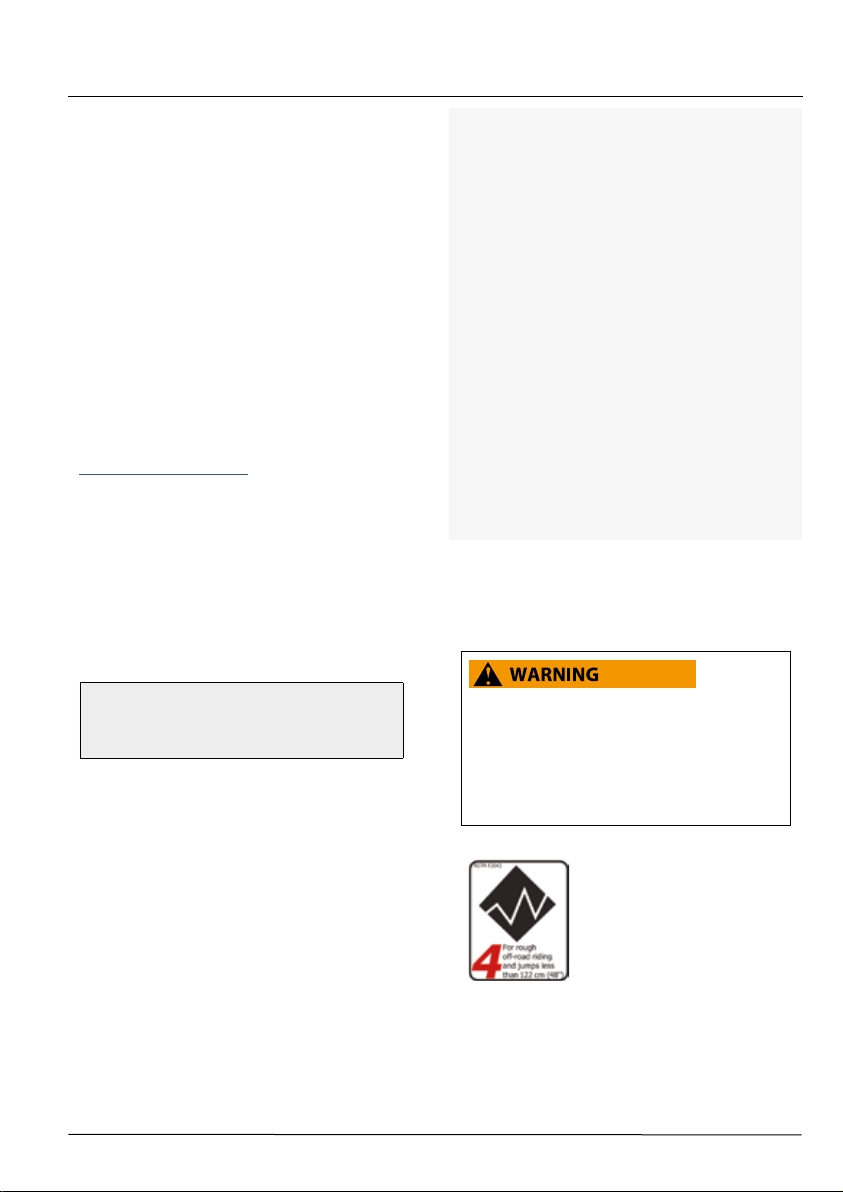
Intended Use
UNDERSTAND YOUR BIKE AND ITS INTENDED
USE. USING YOUR BIKE THE WRONG WAY IS
DANGEROUS.
Please read your Cannondale Bicycle Owner’s
Manual for more information about Intended Use
and Conditions 1-5.
Contacting Cannondale
Cannondale USA
Cycling Sports Group, Inc.
1 Cannondale Way, Wilton CT, 06897, USA
1-800-726-BIKE (2453)
Cycling Sports Group Europe B.V
Mail: Postbus 5100
Visits: Hanzepoort 27
7570 GC, OLDENZAAL, Netherlands
Tel: +41 61 551 14 80
Fax:+31 54 151 42 40
134910 Rev 1.
The intended use of all models
is ASTM CONDITION 4,
All-Mountain.
1
Page 4
‘
SAFETY INFORMATION
Important
Composites Message
Your bike (frame and components) is made from
composite materials also known as “carbon ber.”
All riders must understand a fundamental reality
of composites. Composite materials constructed
of carbon bers are strong and light, but when
crashed or overloaded, carbon bers do not bend,
they break.
For your safety, as you own and use the bike, you
must follow proper service, maintenance, and
inspection of all the composites (frame, stem, fork,
handlebar, seat post, etc.) Ask your Cannondale
Dealer for help.
We urge you to read PART II, Section D. “Inspect For
Safety” in your Cannondale Bicycle Owner’s Manual
BEFORE you ride.
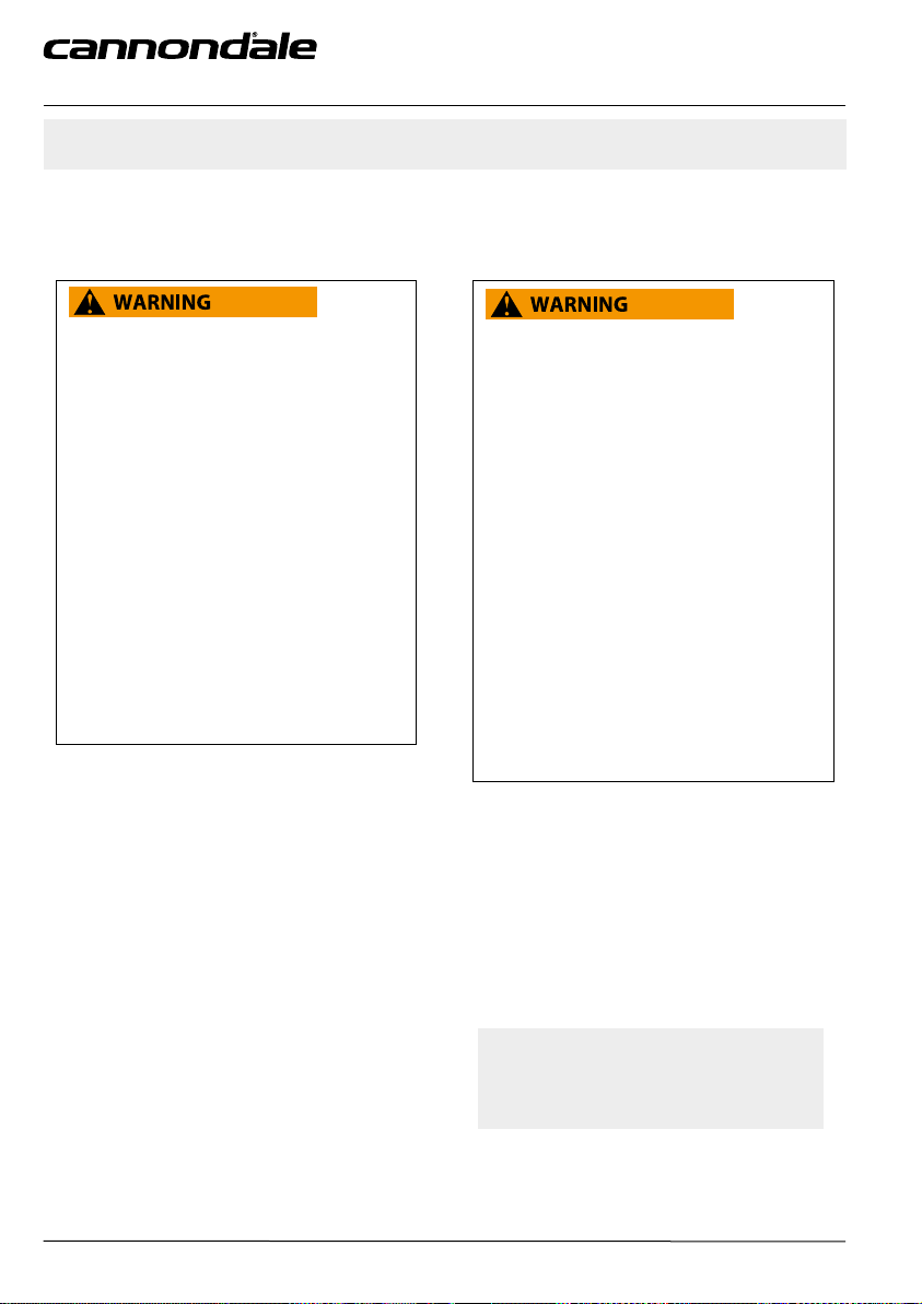
YOU CAN BE SEVERELY INJURED, PARALYZED
OR KILLED IN AN ACCIDENT IF YOU IGNORE THIS
MESSAGE.
Inspection & Crash Damage Of
Carbon Frames/Forks
AFTER A CRASH OR IMPACT:
Inspect frame carefully for damage (See PART II,
Section D. Inspect For Safety in your Cannondale
Bicycle Owner’s Manual. )
Do not ride your bike if you see any sign of damage,
such as broken, splintered, or delaminated carbon
ber.
ANY OF THE FOLLOWING MAY INDICATE A
DELAMINATION OR DAMAGE:
– An unusual or strange feel to the frame
– Carbon which has a soft feel or altered shape
– Creaking or other unexplained noises,
– Visible cracks, a white or milky color present in
carbon ber section
CONTINUING TO RIDE A DAMAGED FRAME
INCREASES THE CHANCES OF FRAME FAILURE,
WITH THE POSSIBILITY OF INJURY OR DEATH OF
THE RIDER.
134910 Rev 1.
YOU CAN BE YOU SERIOUSLY INJURED,
PARALYZED OR KILLED
IF YOU IGNORE WARNINGS.
2
Page 5
TECHNICAL INFORMATION
Frame Specication
FRAME 148 x 12mm Ai
HEAD TUBE 1 1/8 - 1 1/2 Tapered
BOTTOM BRACKET PF30 83mm BB30 83mm
FRONT DERAILLEUR
SEAT POST DIA./BINDER 31.6 mm, 34.9 mm binder
MINIMUM SEAT POST INSERT 100 mm
TIRE SIZE/MAXIMUM WIDTH
MAXIMUM FORK LENGTH
INTENDED USE
REAR TRAVEL 145 mm 165mm
RECOMMENDED SAG 30%, 17 mm 30%, 18 mm
EYE-TO-EYE / STROKE 210 mm / 55 mm 230 mm / 60 mm
REAR BRAKE 160/180 Flat Mount
REAR AXLE 148 X 12 Maxle, 180 mm length
MAXIMUM WEIGHT LIMIT (Lbs/Kg) Total (rider+all equipment): 305lb / 138 Kg
TRIGGER CARBON JEKYLL CARBON JEKYLL ALLOY
Low Direct Mount,
Side Swing
(alloy CS only)
27.5” X 2.5”
545 mm 565 mm
ASTM CONDITION 4, All-Mountain
Please read your Cannondale Bicycle Owner’s Manual for more
information on specication marked with the safety alert symbol “
N/A
ENGLISHTRIGGER/JEKYLL - OWNERS MANUAL SUPPLEMENT
.”
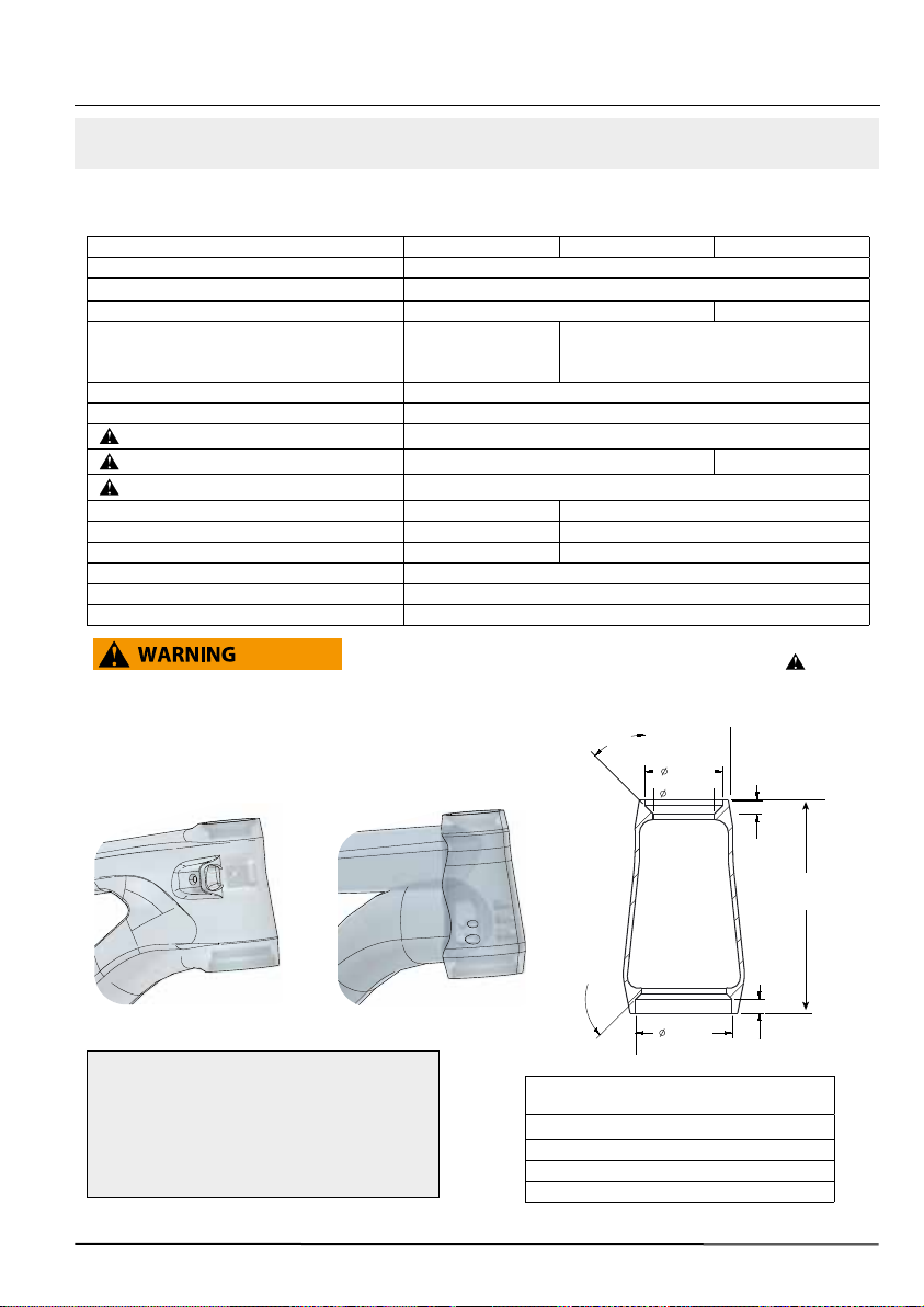
Headtube
(carbon) (alloy)
NOTICE
Do not face, surface, or cut the head tube bearing
cups. When removing adapters, bearings, or cup
from, extra care must be used so that the tool used
to drive out the bearing is not located on any part
a bonded cup.
134910 Rev 1.
45.0°
42.0 mm
33.0 mm
3.0 mm
X
45.0°
52.0 mm
FRAME SIZE
SM 102 mm
MD 115 mm
LARGE 122 mm
X-LARGE 134 mm
3
7.5 mm
HEADTUBE
LENGTH (X)
Page 6

‘
BOTTOM BRACKET PF30
Carbon frames have a 46 mm I.D. bottom bracket bearing system press interface. The shell width is 83mm.
Maintenance
In general, you should inspect the condition of the bearings annually (at a minimum) or anytime the crankset assembly is
disassembled , serviced, or if a problem is indicated.
To inspect, when the crankset is removed, rotate the inner bearing race of both bearings; rotation should be smooth, and
quiet. Execesssive play, roughness or corrossion indicates a damaged bearing.
Removal
To avoid serious damage to the frame, it is important to remove bearing systems very carefully using proper tools
indicated by the manufacture’s service instructions. Make sure the bearings(cup or adpater parts) are driven out squarely
and evenly from inside the shell!!! Do not pry components from shell.
Replacement
PressFit BB30 bearings are not removable from the adapters or cup systems that are pressed into the frame bottom
bracket shell. Therefore, damaged bearings must be removed and replaced as new entire sets. Before installing any new
bearing units into the shell, thoroughly clean the inside surface of the bottom bracket shell with a clean dry shop towel.
Also, make sure both bearing units and the BB shell surfaces are clean and dry. Do not apply grease to either.
Follow the manufacture’s instruction for assembly and installtion of the bearing system. Use a headset press such as Park
Tool HHP-2. See http://www.parktool.com/product/bearing-cup-press-HHP-2 Select appropriate press and adapters to
ensure that force is only applied to the cup and not the bearing inside. Press until the both cup anges are mated to the
BB shell edge.
NOTICE
Consult with your Cannondale Dealer on the quality and compatibilty of any proposed replacement
component.
Make sure the PRESSFIT BB30 system is intended for use with with a 46 mm I.D. BB shell. Conrm acutal
part dimensions with a micrometer.
Do not use chemical solvents to clean. Do not remove frame material or use surfacing tools on bottom
bracket shell.
Frame damage, caused by improper components, component installation or removal is not covered by your
warranty.
134910 Rev 1.
4
Page 7

BOTTOM BRACKET – BB30
The bottom bracket shell is compatible with the BB30 Standard. See http://www.bb30standard.com/ .
Maintenance
Inspect bearing condition annually (at a minimum) and anytime the crankset assembly is disassembled or serviced.
With the crankset removed, rotate the inner bearing race of both bearings; rotation should be smooth. No play or
movement inside the shell. If the bearing is damaged, replace both bearings with new ones.
Bearing Removal
Remove the old bearings with the bearing removal tool KT011/.
Bearing Installation
To install bearings, use a headset press and Cannondale tool KT010/ . Clean inside of shell apply a high-quality
bicycle bearing grease to the inside surface. Press bearing one at a time. Press each bearing until seated. Following
installation, apply a light coating of a high-quality bicycle bearing grease to both sides of each bearing to help repel
moisture.
Do not re-use removed bearings. Install both bearings as a new set.
NOTICE
BEARINGS - Frequent or routine renewal of undamaged bearings is not recommended. Repeated removal
and reinstallation can damage the inside BB shell surfaces resulting in poor bearing t. Do not face, mill
or machine the bottom bracket shell for any reason. Doing so can result in serious damage and possibly a
ruined bike frame.
Do not cut, face, or use abrasives to clean the inside if the BB shell.
We strongly recommend that these procedures be performed by an Authorized Cannondale Dealer.
Damage caused by improper installation/removal is not covered under your warranty.
ENGLISHTRIGGER/JEKYLL - OWNERS MANUAL SUPPLEMENT
134910 Rev 1.
5
Page 8
‘
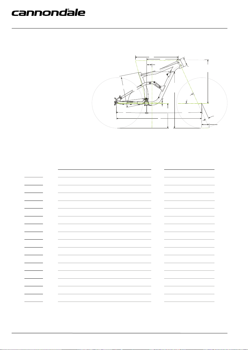
TRIGGER Geometry
A
SEAT TUBE LENGTH
B
TOP TUBE HORIZONTAL
C
TOP TUBE ACTUAL
D
HEAD TUBE ANGLE
E
SEAT TUBE ANGLE EFFECTIVE
F
STANDOVER
G
HEAD TUBE LENGTH
H
WHEELBASE
I
FRONT CENTER
J
CHAIN STAY LENGTH
K
BOTTOM BRACKET DROP
L
BOTTOM BRACKET HEIGHT
M
FORK RAKE
N
TRAIL
O
STACK
P
REACH
Dimensions = (centimeter/inches)
MENS WOMENS
SIZE
A
B
C
D
E
F
G
H
I
J
K
L
M
N
O
P
S M L XL S M
40.0/15.7 43.0/16.9 46.0/18.1 52.0/20.5 40.0/15.7 43.0/16.9
57.6/22.7 60.2/23.7 62.7/24.7 65.5/25.8 57.6/22.7 60.2/23.7
N/A N/A N/A N/A N/A N/A
66°
74.5°
74.9/29.5 76.1/30.0 76.7/30.2 79.6/31.3 74.9/29.5 76.1/30.0
10.2/4.0 11.5/4.5 12.7/5.0 14.0/5.5 10.2/4.0 11.5/4.5
113.0/44.5 115.8/45.6 118.5/46.7 121.5/47.8 113.0/44.5 115.8/45.6
71.1/28.0 73.9/29.1 76.5/30.1 79.5/31.3 71.1/28.0 73.9/29.1
42.0/16.5
1.2/0.5
34.5/13.6
4.4/1.7
10.7/4.2
58.3/23.0 59.5/23.4 60.6/23.9 61.8/24.3 58.3/23.0 59.5/23.4
41.4/16.3 43.7/17.2 45.9/18.1 48.4/19.0 41.4/16.3 43.7/17.2
A
J
H H H
H H H
H H H
H H H
H H H
H H H
H H H
B
P
75 mm
C
E
K
L
H
66°
74.5°
42.0/16.5
1.2/0.5
34.5/13.6
4.4/1.7
10.7/4.2
G
O
F
D
I
M
N
H
H
H
H
H
H
H
All Specifications subject to change without notice.
H - Indicates same.
134910 Rev 1.
6
Page 9

JEKYLL Geometry
A
SEAT TUBE LENGTH
B
TOP TUBE HORIZONTAL
C
TOP TUBE ACTUAL
D
HEAD TUBE ANGLE
E
SEAT TUBE ANGLE EFFECTIVE
F
STANDOVER
G
HEAD TUBE LENGTH
H
WHEELBASE
I
FRONT CENTER
J
CHAIN STAY LENGTH
K
BOTTOM BRACKET DROP
L
BOTTOM BRACKET HEIGHT
M
FORK RAKE
N
TRAIL
O
STACK
P
REACH
Dimensions = (centimeter/inches)
ENGLISHTRIGGER/JEKYLL - OWNERS MANUAL SUPPLEMENT
B
P
75mm
C
A
E
K
J
H
G
O
F
D
L
I
M
N
All Specifications subject to change without notice.
H - Indicates same.
134910 Rev 1.
SIZE
A
B
C
D
E
F
G
H
I
J
K
L
M
N
O
P
S M L XL
40.0/15.7 43.0/16.9 46.0/18.1 52.0/20.5
58.4/23.0 60.9/24.0 63.4/25.0 66.2/26.1
53.7/21.1 56.2/22.1 58.7/23.1 62.1/24.5
65°
75.0°
75.0/29.5 75.8/29.8 76.7/30.2 77.5/30.5
10.2/4.0 11.5/4.5 12.7/5.0 14.0/5.5
116.0/45.7 118.7/46.7 121.4/47.8 124.4/49.0
74.0/29.1 76.7/30.2 79.4/31.3 82.4/32.5
42.0/16.5
0.8/0.3
34.9/13.7
4.4/1.7
11.4/4.5
59.2/23.3 60.4/23.8 61.5/24.2 62.6/24.7
42.5/16.7 44.7/17.6 46.9/18.5 49.4/19.5
H H H
H H H
H H H
H H H
H H H
H H H
H H H
7
Page 10

‘
Dropout
6 Nm
Loctite 242 (blue)
small end
Maintenance
The condition of the bearings, pivot axles, and spacers
should be inspected periodically. These are normal wear
parts so plan to have them renewed as they wear-out.
Inspection frequency should be based upon how and
where you ride. Evidence of damage would be excessive
play, visible wear, or perhaps corrosion of bearings.
If you nd any damage to the parts, discontinue riding
until all the parts (bearings, pivot axles, spacers) can be
renewed. This will help prevent damage elsewhere.
See the kits list in the back of this supplement for
renewal kits.
KP169/
Key Information:
A special service tool KP169/ contains parts necessary
to service the assembly. The parts of this tool are shown
shaded above.
When connecting the seat stays to the dropouts, always
insert the small end of pivot spacers into the dropout
bearings . The at side of the spacers should face out,
as shown.
When tightening the axles, insert the 5 mm hex key
completely into the axle to prevent damage when
turning the bolt. Always tighten with a torque wrench
to the specied torque.
134910 Rev 1.
8
Page 11

Asymmetric Integration - Ai
Rear Wheel- 3 mm Oset
The Ai rear hub is oset 3 mm to the drive side. This both aligns the
cassette with the Ai frame’s 55mm chainline, and aligns the rim/tire
with frame’s centerline for correct tire clearance.
Ai wheels have equal spoke angles and tension on both sides (nondished wheel) which improves wheel stiness, strength.
• The 3mm oset is for 148 X 12mm spacing only!
• Other Ai equipped bike with 142mm or 135mm rear
spacing use a 6mm oset.
NOTICE
USE ONLY 3mm “Ai” OFFSET REAR WHEELS. Incorrect wheel
oset can damage your frame.
Standard wheel assembled on this frame will result in
insucient tire clearance leading to rubbing and serious frame
damage. This kind of damage is not covered by the Cannondale
Limited Warranty.
Building/Truing a Wheel
If you chose to build, or true the wheel, make sure the 3 mm
oset is present. Consult with your Cannondale Dealer if you
have any questions.
ENGLISHTRIGGER/JEKYLL - OWNERS MANUAL SUPPLEMENT
NON-DRIVE DRIVE
3mm
Main Pivot Bearing Tool - CK9017U00OS
Install
134910 Rev 1.
9
148mm
Remove
Page 12

‘
LOCK’R AXLES
1 N-m
134910 Rev 1.
5 N-m
1 N-m
5 N-m
10
Page 13

NGLI-2
ENGLISHTRIGGER/JEKYLL - OWNERS MANUAL SUPPLEMENT
T25
1.
5.0 N-m
4.
M5
3.
M6
1.0 N-m
A
Eastwing.com
12oz/340g
Removal
The axle removal technique is shown removed from for
clarity. See inset A.
Steps:
A. Loosen the screw (4) 4-6 turns using a T25 Torx key.
B. Tap head of M4 screw (4) to un-seat threaded
wedge (2).
Remove M4 screw (4) and threaded wedge (2) from
the axle (1).
C. Insert a 5mm hex key to twist the wedge (3) free
and remove it (shown). If stuck, insert the long side
of a 6mm HEX key (non-ball end) from the threaded
end of axle and tap it out.
D. Insert a 6mm hex key into the axle and turn
counter-clockwise until it can be removed.
2.
a
5mm
Installation
Be sure to inspect the parts for any burrs, scratches or
other damage before assembly. Replace the complete
axle assembly if any damage is found.
• Apply a high-quality bearing grease to all the
parts of the assembly before installing into
the linkage. Be sure to coat all threads, wedge
surfaces and expansion areas.
• Be sure to use the correct length axle and screw
for the specic location. See above.
• Insert the axle (1) into the link from the non-drive
side. and tighten it with an 6mm hex to 1.0Nm.
Do not over-tighten.
• Insert the threaded wedge (2) into the drive side
of the axle and insert the other wedge (3) and
screw (4) opposite and tighten screw with a T25
Torx to 5.0Nm.
134910 Rev 1.
11
Page 14

‘
Tightening Torques
Correct tightening torque for the fasteners (bolts, screws, nuts) on your bicycle is very important to your safety , durability,
and performance of your bicycle.
We urge you to have your dealer correctly torque all fasteners using a torque wrench. If you decide to tighten fasteners
yourself always use a good torque wrench!
Loctite 242 (blue)
6 Nm
Loctite 242 (blue)
2 Nm
Loctite 242 (blue)
pgs.....13
6 Nm
1.5 Nm
NLGI-2
2 Nm
NLGI-2
pgs.....14
6 Nm
Loctite 242 (blue)
pgs.....8
1 Nm
pgs.....15
12 Nm
Loctite 242 (blue)
5 Nm
pgs.....10-11
134910 Rev 1.
12
Page 15

Rear Derailleur Hanger - CK3257U00OS
2.
1.
ENGLISHTRIGGER/JEKYLL - OWNERS MANUAL SUPPLEMENT
2.
M3X12
Hanger Replacement
Hanger replacement kit is available as Cannondale kit
- CK3257U00OS.
The kit includes the hanger (1) and a new pivot bolt
(3). Before installing a new hanger, be sure to clean
any dirt or debris on the dropout with a nylon brush
(old toothbrush). Inspect the area for any damage.
Lightly grease the dropout surface. Apply Loctite 242
(blue) to the pivot bolt (4). Align the hanger on the
opposite side of the dropout and tighten the bolt to
the specied torque.
134910 Rev 1.
3.
5 Nm
Loctite 232
13
Page 16

2 N-m
M5x25
‘
Shimano Di2 Battery
A
(a)
(b)
1.
The rubber grommets
are pressed into the
frame holes when no
battery is installed.
5.
B 2.
3.
5.
Battery Installation
For Di2, use the seat post type battery
(Shimano SM-BTR2)
1. Remove fork and headset from the frame.
2. Attach mounting plate (1) included in Cannondale
kit K32027/ to the battery (2) using two 3mm nylon
ties (3). Make sure the plate lip (a) is aligned with
the case groove on the battery nearer the cable
connection (b). See inset A.
3. Tie a thin dental string (5) to the battery plate
4. Plug in Di2 wire (to junction B) into the battery
5. Use a shift cable inserted into the top tube hole
and out the lower head tube to guide.
Apply light
grease to
threads.
6. Attached the end of the dental thread to the shift
cable and draw the dental thread through and out
the top tube hole.
7. Insert the battery and plate in the bottom of the
head tube and use the dental thread to guide the
battery and plate into position. 5. With the battery
in position as shown, holding the string (5) taught,
apply grease to the screw (6) and tighten to 2 Nm.
The screw threads should cut the string so it can be
removed.
NOTICE
Periodically, check for proper tightness of the
mounting screws. Use a torque wrench. Do not
over-tighten.
134910 Rev 1.
14
Page 17

Internal Guides - KP436/
1 Nm
5 mm
ENGLISHTRIGGER/JEKYLL - OWNERS MANUAL SUPPLEMENT
4mm
5 mm x 2
1 Nm
5 4mm
4mm
Internal Frame Guides:
Install plastic spiral wire wrap (5) over
Di2 wires (6) passing through internal
guide (7).
Use the 4mm guide opening for Di2 wire.
Use the guide inserts in open
locations.
1 Nm
5
4mm
4mm
5 mm
134910 Rev 1.
6
15
5mm
Page 18

‘
Rear Shock - Gemini
Both the TRIGGER and JEKYLL are equipped with FOX Float X or FOX Float DPS rear shocks. The shocks have “Gemini”
technology which allows the rider to switch between two modes on the y using a handlebar remote: Hustle and Flow.
This supplement contains shock specications and recommended settings for the both TRIGGER and JEKYLL. You’ll need
to see the FOX Owner’s Manual for adjustment and maintenance information: www.foxracingshocks.com.
TRIGGER JEKYLL
SAG 30%, 17mm 30%, 18 mm
1
SAG
12 Nm
12 Nm
Flow Mode
Flow mode uses the shock’s entire air chamber and is
ideal for descending and other situations where having
full shock travel is advantageous.
Set to Flow mode: press the black handlebar remote
button (a) releasing the silver button (b).
1.2 Nm
NOTICE
Mount shocks TRIGGER and JEKYLL
in orientation shown: controls
forward and facing up as shown.
Hustle Mode
This mode reduces the usable air volume in the shock
and provides a more supportive, progressive spring
rate for situations like out of the saddle sprinting and
climbing.
To switch the shock to Hustle mode, press the silver
button down until you feel a click and the silver
button remains depressed.
134910 Rev 1.
16
Page 19

ENGLISHTRIGGER/JEKYLL - OWNERS MANUAL SUPPLEMENT
(a)
(b)
To set air pressure:
1. Set handlebar remote to Flow mode: press the
black handlebar remote button (a) so that the
remote handlebar control is in the position shown
below.
2. Remove the Schrader valve cap (1) and pressurize
the shock with a shock pump according to your
riding weight (body weight, clothing and
equipment). Consult the table for your bike/shock.
3. Remove the shock pump.
4. Cycle the shock 10 times to allow the positive and
negative air pressures to equalize.
5. Thread the shock pump back onto the valve and
pump the shock back up the recommended
pressure again to compensate for any transferred air
pressure.
NOTE: Air pressure measured at the pump will
decrease after air has transferred from positive to
negative chambers.
5. Remove the shock pump from the shock valve.
6. Check sag to conrm your shock setup. Recommended seated sag with full riding gear is 30% (see
tables below)
7. If there is too much sag, add air pressure in 10
psi increments until correct sag is achieved. If
there is too little sag, reduce air pressure in 10 psi
increments until correct sag is achieved.
8. Install the Schrader valve cap onto the air valve.
9. Turn the red rebound adjuster clockwise towards
“slow” until it stops.
a. Float X - Insert a 2mm hex wrench into a cutout in
the red rebound knob located near the eyelet on
the frame side of the shock. Use the wrench to turn
the knob towards “slow” until it stops.
b. Float DPS - Turn the red rebound knob located
under the blue compression adjustment lever on
the frame side of the shock clockwise towards
“slow” until it stops.
10. Turn the red rebound knob counter-clockwise
towards “fast”, counting each detent click until you
reach the recommended number of clicks based on
the table below.
Gemini - FOX Float DPS
RIDER WT. AIR PRESSURE REBOUND
Lbs Kg PSI Bar Clicks*
100 45 105 7.2 13
110 50 118 8.1 13
120 55 131 9.0 12
130 59 144 9.9 11
140 64 157 10.8 10
150 68 170 11.7 10
160 73 184 12.7 9
170 77 197 13.6 8
180 82 210 14.5 7
190 86 223 15.4 6
200 91 236 16.3 5
210 95 249 17.2 5
220 100 262 18.1 4
* Fully close the rebound dial, turn clockwise until dial stops. To set count clicks turning counter-clockwise.
134910 Rev 1.
Gemini - FOX Float X (shown)
RIDER WT. AIR PRESSURE REBOUND
Lbs Kg PSI Bar Clicks*
100 45 130 9.0 21
110 50 144 9.9 20
120 55 158 10.9 19
130 59 172 11.9 18
140 64 186 12.9 17
150 68 200 13.8 16
160 73 215 14.8 15
170 77 229 15.8 14
180 82 243 16.7 13
190 86 257 17.7 12
200 91 271 18.7 11
210 95 285 19.6 10
220 100 299 20.6 9
17
Page 20

‘
Remote Cable Installation
1. Cut a piece of derailleur housing that ts from
Gemini’s housing stop to the Gemini remote
without interfering with the rotation of the handle
bars. Install a ferrule on one end of the housing.
2. Place the Gemini remote in Flow mode by pressing
the black button on the Gemini remote while
placing upward pressure on the silver button.
3. Insert a derailleur cable into the round hole below
the silver button on the Gemini remote. Feed the
cable through the remote until the cable head is
fully seated.
4. Insert the cable into the cable noodle end opposite
the barrel adjuster. Slide the cable noodle along the
cable until it is fully inserted into the remote.
5. Insert the derailleur cable into the Gemini cable
housing end with the ferrule and push it through
until the housing is fully seated in the barrel
adjuster on the cable noodle.
6. Insert the derailleur cable through the housing stop
on the Gemini shock, then pull the cable until the
housing is fully seated in the housing stop. There
should not be a housing ferrule on this side of the
Gemini housing.
7. Use a 2 mm hex wrench to loosen the set screw
located on the rear of the Gemini shock cam until
there are only 2 threads engaged.
8. Insert the cable between the set screw and Gemini
cam. Pull the cable so the cable and housing are
fully seated and tight.
9. Tighten the set screw to 1.2 Nm with a 2mm hex
wrench to secure the cable.
10. Function Test: Push on the remote’s silver Hustle
mode button, then press the black Flow mode
button.
a. Cable is too tight: the remote cannot stay in Hustle
mode. Reduce cable tension by turning barrel
adjuster clockwise. If problem persists, reduce cable
tension by loosening the set screw and resetting
cable tension as described in steps 7-9.
b. Cable is too loose: the cam will not turn as soon
as you engage the lever. Increase cable tension
by turning the barrel adjuster counter-clockwise.
If problem persists increase cable tension by
loosening the set screw and resetting cable tension
as described in steps 7-9.
SELECT ONLY COMPATIBLE SHOCKS AND FORKS
FOR YOUR BIKE. DO NOT MODIFY YOUR BIKE IN
ANY WAY TO MOUNT ONE. HAVE YOUR SHOCK
OR FORK INSTALLED BY A PROFESSIONAL BIKE
MECHANIC
• Riding with the wrong rear shock can damage
the frame. You could have a serious accident.
Make sure the total travel, eye-to-eye length,
and stroke length of the rear shock you select
meet the SPECIFICATIONS listed in this manual.
• When selecting dierent shocks or forks for
your bike, make sure that the shock or fork you
select is compatible with your bike’s design
and how you will use your bike.
YOU CAN BE YOU SERIOUSLY INJURED,
PARALYZED OR KILLED IF YOU IGNORE THESE
WARNINGS.
134910 Rev 1.
18
Page 21

MAINTENANCE
The following table lists only supplemental maintenance items. Please consult your Cannondale Bicycle Owner’s
Manual for more information on basic bike maintenance. Consult with your Authorized Cannondale Dealer to create
a complete maintenance program for your riding style, components, and conditions of use. Follow the maintenance
recommendations given by the component manufacturer’s for the various parts of your bike.
ITEM FREQUENCY
HOUSING AND CABLES - Your bike has been supplied with small adhesive
frame protectors - KF103/. Place this material on the the frame between where
cables and housing rub due to movement. Overtime, cable rubbing can wear
into the frame itself causing very serious frame damage.
NOTE: Damage to your bike caused by cable rubbing is not a condition
covered under your warranty. Also, adhesive frame guards are not a x for
incorrectly installed or routed cables or lines. If you nd that applied guards
are wearing out very quickly, consult with your Cannondale Dealer about the
routing on your bike.
DAMAGE INSPECTION - Clean and visually inspect entire bike frame/swing
arm/linkage assembly for cracks or damage. See “Inspect For Safety” in your
Cannondale Bicycle Owner’s Manual.
CHECK TIGHTENING TORQUES - In addition to other component specic
tightening torques for your bike. Tighten according to the “TIGHTENING
TORQUES” information listed in this supplement.
DISASSEMBLE, CLEAN, INSPECT, RE-GREASE, REPLACE WORN OR
DAMAGED PARTS IN THE FOLLOWING ASSEMBLIES:
• SHOCK LINK ASSEMBLY • PIVOT AXLES • FRAME PIVOT
BEARINGS
BEFORE FIRST RIDE
BEFORE AND AFTER EACH RIDE
EVERY FEW RIDES
IN WET, MUDDY, SANDY
CONDITIONS EVERY 25 HRS.
IN DRY, CONDITIONS
EVERY 50 HRS.
ENGLISHTRIGGER/JEKYLL - OWNERS MANUAL SUPPLEMENT
FORK and SHOCK: - Please consult the manufacturer’s owner’s manual for maintenance information.
ANY PART OF A POORLY MAINTAINED BIKE CAN BREAK OR MALFUNCTION LEADING TO AN ACCIDENT WHERE
YOU CAN BE KILLED, SEVERELY INJURED OR PARALYZED.
Please ask your Authorized Cannondale Dealer to help you develop a complete maintenance program, a program
which includes a list of the parts on your bike for YOU to check regularly. Frequent checks are necessary to identify the
problems that can lead to an accident.
134910 Rev 1.
19
Page 22

34.9 mm
M
L
‘
TRIGGER (Carbon)
CS-L
REPLACEMENT PARTS
H
M4
Loctite 242 (blue)
6 Nm
M2.5
Loctite 242 (blue)
2 Nm
CS-R
DT & SS
A
F
D
F
I
ID CODE DESCRIPTION
CK3147U00OS
A
B
C
D
E
F
CK3177U00OS
CK3227U00OS
CK3257U00OS
KP421/160
KP421/180
CK3237U00OS
Trigger Pivot Hardware
Trigger Pivot Bearings
Trigger Shock Bolts
Jekyll/Trigger Rear Der Hanger
Brake Mount Flat 160mm
Brake Mount Flat 180mm
Trigger CRB Cstay Protector
G CK3287U00OS Trigger CRB Cstay Guard
A
J
E
B
C
Loctite 242 (blue)
M4
Loctite 242 (blue)
6 Nm
G
12 Nm
A
K
A
ID CODE DESCRIPTION
K34068
H
I
J
K
K34058
CK3247U00OS
C22698M00L1
KP390/
Trigger CRB CS Heel Rub Grds
( Trigger 1)
Trigger ALLY CS Heel Rub Grds
(Trigger 2 and 3)
Trigger Al Chainstay Protector
27.5 M Trigger Crb Link
Mount F Der
134910 Rev 1.
20
Page 23

ENGLISHTRIGGER/JEKYLL - OWNERS MANUAL SUPPLEMENT
M
34.9 mm
A
1.5 N-m
B
L
Q
M2.5
1 N-m
N
M2.5
1 N-m
P
M2.5
C
M5
Loctite 242 (blue)
12 Nm
O
1 N-m
P
Q
Q
ID CODE DESCRIPTION
CK9017U00OS
L
M
KP197/SRM
KP388/
17x30 Bearing Tool
Kit Bearing BB-Presst 30 SRM
Seatbinder MTN 34.9
For rear shock parts and service:
www.foxracingshocks.com
134910 Rev 1.
ID CODE DESCRIPTION
K32027
N
Internal Di2 Battery Mount
0 CK3117U00SM Trigger Crb DT Protector SM
CK3117U00MD Trigger Crb DT Protector MD
CK3117U00LG Trigger Crb DT Protector LG
CK3117U00XL Trigger Crb DT Protector XL
CK3187U00OS
P
KP436/
M
Jekyll/Trigger Grommets
Cable Guides Scalpel Si
21
Page 24

Loctite 242 (blue)
12 Nm
A
N
‘
REPLACEMENT PARTS
JEKYLL (Carbon/Alloy)
F
C
Loctite 242 (blue)
12 Nm
1
2 N-m
M5x25
E
G
D
D
A
1
1.5 Nm
H
B
F
34.9 mm
I
= NLGI-2 Synthetic Grease
1
ID CODE DESCRIPTION CRB ALLY
CK3157U00OS
A
B
C
D
E
F
CK3167U00OS
CK3207U00OS
K36018
CK3187U00OS
KP388/
KP436/
KP197/SRM
KB6180/
QC616/
Jekyll Pivot Hardware X X
Jekyll Pivot Bearings X X
Jekyll Carbon Shock Bolts X
Jekyll Alloy Shock Bolts X
Jekyll/Trigger Grommets X X
Seatbinder MTN 34.9 X X
Cable Guides Scalpel Si X
Kit Bearing BB-Presst 30 SRM X
Bearing BB Si 2PCS BLU X
Circlips 2x BB Si X
134910 Rev 1.
ID CODE DESCRIPTION CRB ALLY
K32027
G
H
I
CK3107U00SM
CK3107U00MD
CK3107U00LG
CK3107U00XL
K34008
CK9017U00OS
Internal Di2 Battery Mount X
Jekyll Crb DT Protector SM X
Jekyll Crb DT Protector MD X
Jekyll Crb DT Protector LG X
Jekyll Crb DT Protector XL X
Jekyll Alloy DT Protector (all sizes) X
17x30 Bearing Tool X X
22
Page 25

ENGLISHTRIGGER/JEKYLL - OWNERS MANUAL SUPPLEMENT
Loctite 242 (blue)
12 Nm
A
C
A
Loctite 242 (blue)
N
M
5 Nm
K
L
For rear shock parts and service:
www.foxracingshocks.com
A
A
W
L
2 Nm
6 Nm
M5 X 18
A
CS-L
O
CS-R
DT & SS
P
Loctite 242 (blue)
6 Nm
B
ID CODE DESCRIPTION CRB ALLY
CK3257U00OS
J
K
L
M
N
O
P
CK3217U00OS
CK3197U00OS
K34078
C21698M00L1
K34068
K34058
KP421/160
KP421/180
Jekyll/Trigger Rear Der Hanger X X
Jekyll AL CSTAY Protector X
Jekyll CRB CSTAY Protector X
Jekyll CRB Chainsuck Protector X
27.5 M Jekyll CRB Link (w/bearings)
All sizes, both carbon and alloy
Jekyll CRB CS Heel Rub Grds (Jekyll 1) X
Jekyll/ ALLY CS Heel Rub Grds
(Jekyll 2, 3,4)
Brake Mount Flat 160mm X X
Brake Mount Flat 180mm X X
134910 Rev 1.
X X
X
23
Page 26

CANNONDALE USA
Cycling Sports Group, Inc.
1 Cannondale Way,
Wilton CT, 06897, USA
1-800-726-BIKE (2453)
CANNONDALE EUROPE
Cycling Sports Group Europe B.V
Mail: Postbus 5100
Visits: Hanzepoort 27
7570 GC, OLDENZAAL, Netherlands
Tel: +41 61 551 14 80
Fax:+31 54 151 42 40
WWW.CANNONDALE.COM
© 2017 Cycling Sports Group
TRIGGER/JEKYLL Owner’s
Manual Supplement - 134910 Rev 1
 Loading...