

Page 1
SYNAPSE
OWNER’S MANUAL SUPPLEMENT
Read this supplement and your Cannondale Bicycle Owner’s Manual.
Both contain important safety information. Keep both for future reference.
Page 2
Explicit Denitions
In this supplement, particularly important information is
presented in the following ways:
DANGER
Indicates a hazardous situation which, if not avoided,
will result in death or serious injury.
Indicates a hazardous situation which, if not avoided,
may result in death or serious injury.
NOTICE
Indicates special precautions that must be taken to
avoid damage.
134917 Rev 1.
Page 3
ENGLISHSYNAPSE - OWNERS MANUAL SUPPLEMENT
ENGLISH
Cannondale Supplements
This manual is a “supplement” to your Cannondale
Bicycle Owner’s Manual.
This supplement provides additional and important
model specic safety, maintenance, and technical
information. It may be one of several important
manuals/supplements for your bike; obtain and read all
of them.
Please contact your Authorized Cannondale Dealer
immediately if you need a manual or supplement, or
have a question about your bike. You may also contact
us using the appropriate country/region/location
information. See Contacting Cannondale in this
supplement.
You can download Adobe Acrobat PDF versions of any
manual/supplement from our website:
http://www.cannondale.com
Your Authorized
Cannondale Dealer
To make sure your bike is serviced and maintained
correctly, and that you protect applicable warranties,
please coordinate all service and maintenance through
your Authorized Cannondale Dealer.
NOTICE
Unauthorized service, maintenance, or repair parts
can result in serious damage and void your warranty.
CONTENTS
Safety Information .............................. 1-4
Technical Information .......................5-12
Replacement Parts................................ 13
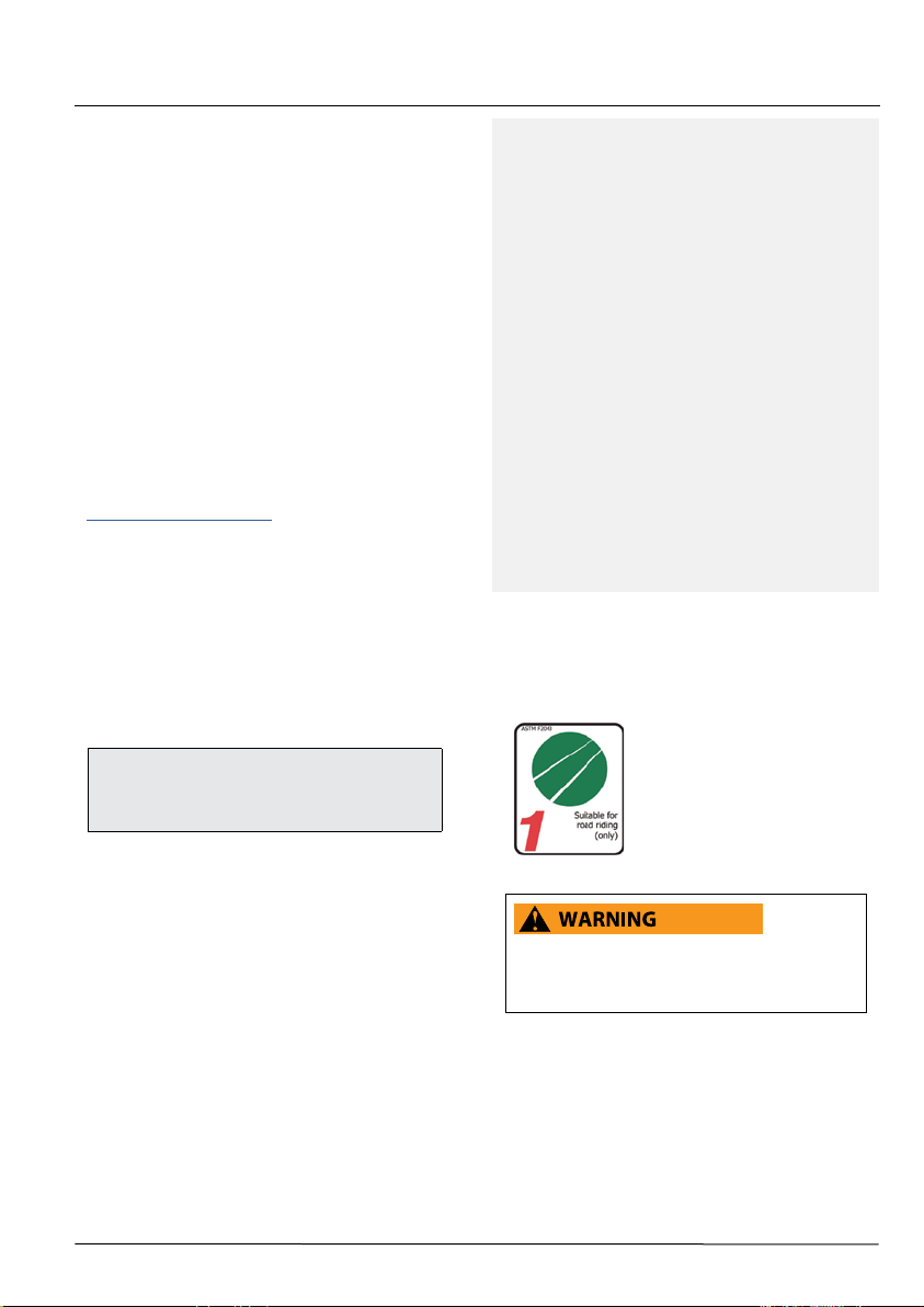
Intended Use
The intended use of all models is
ASTM CONDITION 1,
High-Performance Road.
Contacting Cannondale
Cannondale USA
Cycling Sports Group, Inc.
1 Cannondale Way, Wilton CT, 06897, USA
1-800-726-BIKE (2453)
Cycling Sports Group Europe B.V
Mail: Postbus 5100
Visits: Hanzepoort 27
7570 GC, OLDENZAAL, Netherlands
Tel: +41 61 551 14 80
Fax:+31 54 151 42 40
134917 Rev 1.
Please read your Cannondale Bicycle Owner’s
Manual for more information about Intended Use
and Conditions 1-5.
1
Page 4
SYNAPSE - OWNERS MANUAL SUPPLEMENT
SAFETY INFORMATION
Important Composites
Message
Your bike (frame and components) is made from
composite materials also known as “carbon ber.”
All riders must understand a fundamental reality
of composites. Composite materials constructed
of carbon bers are strong and light, but when
crashed or overloaded, carbon bers do not bend,
they break.
For your safety, as you own and use the bike, you
must follow proper service, maintenance, and
inspection of all the composites (frame, stem, fork,
handlebar, seat post, etc.) Ask your Cannondale
Dealer for help.
We urge you to read PART II, Section D. “Inspect For
Safety” in your Cannondale Bicycle Owner’s Manual
BEFORE you ride.
YOU CAN BE SEVERELY INJURED, PARALYZED
OR KILLED IN AN ACCIDENT IF YOU IGNORE THIS
MESSAGE.
Inspection & Crash Damage Of
Carbon Frames/Forks
AFTER A CRASH OR IMPACT:
Inspect frame carefully for damage (See PART II,
Section D. Inspect For Safety in your Cannondale
Bicycle Owner’s Manual. )
Do not ride your bike if you see any sign of damage,
such as broken, splintered, or delaminated carbon
ber.
ANY OF THE FOLLOWING MAY INDICATE A
DELAMINATION OR DAMAGE:
· An unusual or strange feel to the frame
· Carbon which has a soft feel or altered shape
· Creaking or other unexplained noises,
· Visible cracks, a white or milky color present in
carbon ber section
CONTINUING TO RIDE A DAMAGED FRAME
INCREASES THE CHANCES OF FRAME FAILURE,
WITH THE POSSIBILITY OF INJURY OR DEATH OF
THE RIDER.
134917 Rev 1.
YOU CAN BE YOU SERIOUSLY INJURED,
PARALYZED OR KILLED
IF YOU IGNORE WARNINGS.
2
Page 5
ENGLISH
Disc Brake on Road Bikes
Relative to conventional rim brakes, disc brakes are
less aected by water, do not wear or heat the rims
and therefore are more consistent. Disc brakes also
may be more powerful.
To minimize risk of injury or accidents:
· Understand that road bikes have a relatively
small tire contact patch (part of the tire that
touches the road). In order to apply the brakes
safely and eectively, you may need more or less
braking force in dierent situations. You need
to take into account various road and weather
conditions that can aect traction.
· Disc brakes are excellent, but not some kind of
magic. Take some time riding your new disc brake
road bike in lower risk circumstances to get used
to the feel and performance of the disc brakes
and tires.
YOU CAN BE SEVERELY INJURED, PARALYZED OR
KILLED IN AN ACCIDENT IF YOU IGNORE THIS
MESSAGE.
Tightening Torques
Correct tightening torque for the fasteners (bolts,
screws, nuts) on your bicycle is very important to your
safety. Correct tightening torque for the fasteners is
also important for the durability and performance of
your bicycle. We urge you to have your Dealer correctly
torque all fasteners using a torque wrench. If you decide
to torque fasteners yourself always use a torque wrench.
Find Tightening Torque Information :
The wide range of bicycle models and components
used means that a listing of tightening torque would
be out of date by the time it was published. Many
fasteners should be installed with a thread locking
adhesive such as Loctite®.
To determine correct tightening torque and any
adhesive application for a fastener we ask you to
check:
• Many components are marked. On-product
marking is becoming common.
• Torque specs in the component manufacturers
instructions shipped with your bicycle.
• Torque specs listed on the websites of
component manufacturers.
• With your Dealer. Dealers have access to
current data and have experience with correct
torque for most fasteners.
134917 Rev 1.
3
Page 6

Trainers
If you ride a trainer that requires removal of the front
wheel and clamps the fork dropouts: Be sure your fork
quick release is tight! Relative movement will wear parts,
weaken and damage your bike.
If you ride a trainer that holds the bike up by clamping
the rear quick release between two cones: Take o the
nice, lightweight quick release that came with your
bike. Substitute a heavy, classic all steel quick release
and clamp it tight! Relative movement will wear parts,
weaken and damage your bike. Note that many modern
quick releases will not t the clamping cones in this kind
of trainer because their shapes are incompatible.
For thru axles, make sure you follow the trainer
manufacturer instructions for the use of any
specialized adapters
Be particularly cautious with a carbon frame or fork.
Carbon is relatively soft, not abrasion resistant. If there is
any relative movement, carbon will wear quickly.
If you ride a trainer a lot, consider using an old bike:
Corrosion from sweat will take it’s toll. Weight is
irrelevant. Save wear on your expensive components.
Ask you dealer for help with trainers, the right one
and the correct way to use it.
NOTICE
TRAINERS - Improperly mounting a bike in a trainer,
or using one that is not compatible with your
particular bike frame can cause serious damage.
WATER BOTTLES - An impact, crash, or loose bottle
cage can result in damage to your frame.
This kind of damage is not covered by the Cannondale
Limited Warranty.
Water Bottles
Side impacts to a water bottle or cage can result in
damage threaded inserts due to the leverage on a very
small area. In a crash, certainly the last thing you should
be worried about is saving the threaded inserts in your
frame. However, when you are storing or transporting
your bike, take steps to prevent situations where a water
bottle may be hit or bumped by a strong force that
would cause damage. Remove bottle and cage when
you are packing your bike for travel.
Periodically check the attachment of the bottle cage;
tighten the cage bolts if necessary. Don’t ride with a
loose bottle cage. Riding with loose cage bolts can
produce a rocking motion or vibration of the attached
cage. A loose cage will damage the insert and possibly
lead to the inserts to pull out.
It may be possible to repair a loose insert, or install
another insert only if the frame is undamaged.
Replacement requires the use of a special tool. If you
notice damage to the threaded insert, please ask your
Cannondale Dealer for help.
Building Up A Frame Set
Before building up a frame set, consult with your
Cannondale Dealer and the component manufacturers,
and discuss your riding style, ability, weight, and interest
in and patience for maintenance.
Make sure the components chosen are compatible with
your bike and intended for your weight and riding style.
Generally speaking, lighter weight components have
shorter lives. In selecting lightweight components, you
are making a trade-o, favoring the higher performance
that comes with less weight over longevity. If you
choose more lightweight components, you must inspect
them more frequently. If you are a heavier rider or have a
rough, abusive or “go for it” riding style, buy heavy duty
components.
Read and follow the component manufacturers
warnings and instructions.
134917 Rev 1.
4
Page 7

TECHNICAL INFORMATION
Frame Specication
FRAME Synapse HM, Synapse Carbon
HEAD TUBE See, “Headset Bearings”
BOTTOM BRACKET BB30A 73mm
FRONT DERAILLEUR braze-on / 1X
SEAT POST DIA 25.4 mm
MINIMUM SEAT POST INSERT 65 mm
BRAKES Flat Mount
REAR AXLE 142 x 12mm. M12 x 1.0
MAXIMUM WEIGHT LIMIT (Lbs/Kg) 275/125
Headset Bearings - (size specic)
ENGLISHSYNAPSE - OWNERS MANUAL SUPPLEMENT
FRAME SIZE
(cm)
56, 58, 61 1 1/8”
51, 54 1 1/4”
44, 48 1 1/8”
UPPER BEARING LOWER BEARING OFFSET CROWN DIA.
ACB 45/45, 41.8mm O.D.
FSA - MR121
Cannondale- K35018/
1 3/8”
ACB 36x45, 48.9mm O.D.
FSA - MR031
Cannondale - K35038
ACB 45/45, 46.8mm OD
FSA - MR082
Cannondale - K35028
ACB 45/45, 41.8mm OD
FSA MR121 / K35018
45mm 54mm
55mm 52mm
60mm 50 mm
NOTICE
Do not face, surface, or cut the head tube bearing
cups. When removing adapters, bearings, or cup
from, extra care must be used so that the tool used
to drive out the bearing is not located on any part
a bonded cup.
134917 Rev 1.
5
Page 8

Bottom Bracket – BB30A 73mm
KB6180/
QC616/
KP249/BLK
The small hole in the cable guide cover is
to allow any accumulated water inside the
frame to drain out.
Check to make sure it remains open.
SI HOLLOWGRAM BB30A-73
Si Spindle Length 109 mm
Spacer Left (non-drive) 2.5 mm
Spacer Right (drive) 2.6 mm
RD
FD
CK3588U00OS
BB30A
“asymmetric”
73mm(5mm)
39mm 34mm
Non-Drive Side Drive Side
30mm
42mm
KT011/
134917 Rev 1.
KT010/
6
Page 9

ENGLISHSYNAPSE - OWNERS MANUAL SUPPLEMENT
RB
FD
Bearings
Inspect bearing condition annually (at a minimum)
and anytime the crank set assembly is disassembled
or serviced. With the crank set removed, rotate the
inner bearing race of both bearings; rotation should be
smooth. No play or movement inside the shell. If the
bearing is damaged, replace both bearings with new
ones.
Remove the old bearings with the bearing removal tool
KT011/.
To install bearings, use a headset press and Cannondale
tool KT010/ . Clean inside of shell apply a high-quality
bicycle bearing grease to the inside surface. Press
bearing one at a time. Press each bearing until seated.
Following installation, apply a light coating of a highquality bicycle bearing grease to both sides of each
bearing to help repel moisture.
Do not re-use removed bearings. Install both bearings
as a new set.
NOTICE
BEARINGS - Repeated removal and reinstallation
can damage BB shell surfaces resulting in poor
bearing t.
• Do not face, mill or machine the bottom
bracket shell for any reason.
• Repeated removal and reinstallation of BB
components could result in damage to the
shell and is not recommended.
Damage caused by improper installation/
removal is not covered under your warranty.
BB Internal Routing
RD
134917 Rev 1.
NOTICE
Keep all cables and wires outside the inner bonded
(a)
RB
1
7
alloy BB shell (1). Do not route cables or wires inside
the inner alloy shell.
Secure all mechanical cables and electronic
wires safely inside the frame, so they cannot
unintentionally enter the inner alloy BB shell
through the access holes (a). The access holes are
only to support installation and removal of parts
through the frame tube easier. Do not permit cables
or wires to unintentionally enter the shell through
these holes.
Mechanical cables and electronic wires that contact
the rotating crank set spindle can cause serious
component damage.
Page 10

Geometry
A Seat Tube Length
B Top Tube Horizontal
D Head Tube Angle
B
P
E Seat Tube Angle
F Standover
G Head Tube Length
H Wheelbase
I Front Center
J Chain Stay Length
K Bottom Bracket Drop
L Bottom Bracket Height
M Fork Rake
N Trail
O Stack
A
J
75.0
O
F
E
K
L
D
I
P Reach
Z Head Tube Height
Dimensions = (centimeter/inches)
SIZE
44 48 51 54 56 58 61
H
A 37.0/14.6 40.7/16.0 44.3/17.4 48.0/18.9 52.0/20.5 55.0/21.7 59.0/23.2
B 50.5/19.9 51.7/20.4 53.1/20.9 54.7/21.5 56.1/22.1 57.9/22.8 60.4/23.8
C
D 70.2° 70.8° 71.7°
H
73.0°
H H
E 74.7° 74.6° 74.3° 73.9° 73.5° 73.0° 72.5°
E’
F
G 10.3/4.1 12.2/4.8 13.7/5.4 16.1/6.3 17.3/6.8 19.7/7.8 22.9/9.0
H 98.9/38.9 99.6/39.2 99.4/39.2 100.8/39.7 99.5/39.2 100.9/39.7 102.8/40.5
I 59.1/23.3 59.8/23.5 59.6/23.5 60.9/24.0 59.6/23.5 60.9/24.0 62.7/24.7
J 41.0/16.1
K 7.5/3.0
L 27.0/10.6
M 6.0/2.4
N 6.0/2.4 5.6/2.2 5.6/2.2
H H H H H H
H H
H H
H
5.5/2.2
7.3/2.9
27.2/10.7
H
H
H
H
4.5/1.8
5.8/2.3
7.0/2.8
27.5/10.8
H H
H H
O 51.0/20.1 53.0/20.9 55.0/21.6 57.0/22.5 59.0/23.2 61.0/24.0 64.0/25.2
P 36.5/14.4 37.1/14.6 37.7/14.8 38.2/15.1 38.6/15.2 39.3/15.5 40.2/15.8
Z 38.1/15.0
H H H H H H
G
Z
M
N
H
H
All Specications subject to change without notice.
* - Indicates same.
134917 Rev 1.
8
Page 11

Seat Post
A
(b)
ENGLISHSYNAPSE - OWNERS MANUAL SUPPLEMENT
2
1
65mm
(a)
B
4mm
KF115/ - Carbon Gel
5 Nm
To adjust the seat post height:
1. Insert 4mm hex through the underside seat tube
opening (a) as shown.
2. Loosen the binder screw (1) sucient to move the
seat post up or down.
3. Set the seat post (2) position.
Make sure the seat post is visible through the
inspection hole (b) (inset B). This ensures 65mm
Minimum Seat Post Insertion.
4. Tighten the binder screw to 5 Nm.
To remove binder:
1. Loosen binder screw (1) and remove the seat post.
2. Use the 4mm allen hex tool to push the binder out
of the top of the seat tube. See inset A.
For more information about carbon ber seat posts, see also
“APPENDIX D. Care and Maintenance of Carbon Fiber Seat Posts” in
your Cannondale Bicycle Owner’s Manual.
134917 Rev 1.
NOTICE
Use only a 25.4mm seat post. Do not use shims or
adapters.
Do not force a seat post into the frame.
Frame Size
(cm)
44 100
48 110
51 120
54 130
56 170
58 200
61 240
If the seat post length is cut, make sure the 65mm
minimum insert length is maintained.
Periodically clean and apply carbon gel KF115/ to
the inside of the seat tube and the seat post. Do not
use grease.
If a SHIMANO Di2 system battery is installed in the
seat post ensure, sucient wiring length to prevent
damage or battery disconnection.
9
Maximum Seatpost
Depth (mm)
Page 12

SiSL Compression Assembly - K35058
CAP
EXPANDER BOLT
UPPER CONE
WEDGES
O-RING
LOWER CONE
Exploded Parts View
HEADSET SPACERS
3 mm
FORK STEERER
HEADSET TOP CAP
Installation
1. Assemble the fork, headset, spacers, and stem into
the head tube. The fork steerer is to extend 3mm
above the top of the stem.
2. Lightly tighten the stem bolts.
3 Set-up the compression assembly to 45mm length.
Adjust the length by threading the cap on the
upper cone.
4. Insert the compression assembly into the steerer
tube.
5. Insert an 4mm Allen key through the hole in
the cap and into the expander bolt. Tighten the
expander bolt to 4 Nm.
6. Set bearing preload. Insert a 5mm allen key into the
cap. Turn the entire top cap clockwise to increase
bearing preload. Turning it counter-clockwise will
decrease the preload.
45 mm
Set-Up Length
4 Nm
STEM
55mm
Maximum
Stack
Height
EXPANDER BOLT
5
7. When the headset preload is set, turn the stem
to align the handlebar with the front wheel and
tighten the stem clamp bolts to the torque specied
for the stem. Consult the stem manufacturer’s
instructions. The torque values for components are
often marked on the part.
The installation and adjustment to be performed by
a professional bike mechanic. Incorrect installation
can result damage leading to a accident.
DO NOT EXCEED THE MAXIMUM STACK HEIGHT
(55mm) OR LOCATE SPACERS ON TOP OF THE
STEM.
YOU CAN BE SEVERELY INJURED, PARALYZED OR
KILLED IN AN ACCIDENT IF YOU IGNORE THESE
WARNINGS.
134917 Rev 1.
10
Page 13

Di2 Battery Seat Post Installation
ENGLISHSYNAPSE - OWNERS MANUAL SUPPLEMENT
SEAT POST
Seatpost O-Ring
Cannondale SAVE 25.4 21.3 3.0X15 3.0 15
FSA SL-K 25.4 20.3 2.5X15 2.5 15
Cannondale C2 25.4 19.0 1.5X15 1.5 15
The Shimano Di2 battery ts within the inside diameter
of the seat post.
The battery is retained by the placement of specically
sized O-rings on the outside of the battery as marked by
the Cannondale label applied to it.
The O-rings, when installed properly are sucient to
retain the battery. See the table above.
To install the O-ring:
Select the correct size O-rings for the seat post in use.,
Clean the outside of the battery surface with a clean lintfree shop towel. Also clean the inside of the seat post.
Position the three O-ring on the label surface as
indicated.
O.D.
(mm)
I.D.
(mm)
Width
(mm)
I.D.
(mm)
O-RINGS
(end of)
SEAT POST
DI2 BATTERY
Insert Stop Limit
Insert the batter and O-rings into the bottom of the seat
up to the “STOP Insert” red line limit.
When installing the battery tted seat post into the
frame, make sure there is adequate slack in the harness
wiring to enable removal or seat post adjustment.
NOTICE
• Do not use any cleaners or solvents on the
battery or seat post.
• It is important that you DO NOT use grease or
other lubricants which will cause the O-rings
to slide.
• When installing the battery tted seat post
into the frame, make sure there is adequate
slack in the harness wiring to enable removal
or seat post adjustment.
134917 Rev 1.
11
Page 14

DT Guide Congurations
3
1
(c)
3
(a)
(b)
2
1
(c)
3
(a)
2
4
5
(b)
2
Shimano Di2
• Insert Shimano junction box, RS910 (1) , into DT
guide base (2) before nal assembly into the
frame making sure the charging port is towards
the rear of the bike.
• Rotate the junction box 15 degrees in the base to
secure its position.
• Attach E-Tube wires.
• Hook the rear of the guide (a) into the DT port (b)
and then continue to push the guide in the DT.
Make sure the forward tab (c) is hooked under the
front of the DT port.
• Install the DT Guide – Di2 Cap (3) starting from the
back and working forward.
SRAM eTap
• Hook the rear of the guide into the DT port and
then continue to push the guide base (2) in the
DT port (a).
• Make sure the forward tab is hooked under the
front of the DT port wall.
• Install the DT Guide – eTap Cap (4) starting from
the back and working to front.
(a)
(b)
FRONT
1
(c)
2
4
2
Mechanical
• Loosen the bolt (5) enough so the head is above
the top of the mechnical DT guide (6).
• Hook the rear of the guide into the DT port and
• Make sure the forward tab is hooked under the
• Tighten the bolt until the head is lightly seated.
134917 Rev 1.
then continue to push the guide in the DT.
front of the DT port.
DO NOT OVER-TIGHTEN.
6
12
Page 15

Replacement Parts
Loctite 242 (blue)
2 Nm
Loctite 242 (blue)
2 Nm
B
ENGLISHSYNAPSE - OWNERS MANUAL SUPPLEMENT SYNAPSE - OWNERS MANUAL SUPPLEMENT
C
KF115/
K35058/
L
A
eTap
Di2
H
I
G
H
ID CODE DESCRIPTION
CK1168U10OS
A
B
C
D
E
F
G
K11018
KP448/
CK3588U00OS
CK3568U00OS
K32048
CK3578U00OS
CK3598U00OS
Adjustable Fender Bridge BLK
Road Fender Mount Hardware
Seat Binder Wedge Super X
BB Cable Guide
Synapse Crb DT Cable Guide
Shift And Brake Grommets
Synapse Crb FD 1X Cover
Synapse Crb FD Hanger
H KP302/ Dropout Cable Stop 20X
KP419/
I
Der Hanger X12
E
F
eTap
Di2
Di2
eTap
K
J
F
B
Loctite 242 (blue)
D
2 Nm
ID CODE DESCRIPTION
K
L
j
K35018
K35028
K35038
KB6180/
QC616/
K83038
K83048
K83058
K83068
K35058
KF115/
1 1/8 Crb Headset No Crown Race
1 1/4 Crb Headset No Crown Race
1 3/8 Crb Headset No Crown Race
Bearing BB Si 2PCS BLU
Circlips 2x BB Si
Ratchet Lever Maxle 100x12 125mm
Adjustable Lever Maxle 100x12 125mm
Ratchet Lever Syntace 142x12 165mm
Adjustable Lever Syntace 142x12 165mm
SiSL Compression Assy.
Kit Gel Dynamic Carbn Seatpost
134917 Rev 1.
13
Page 16

CANNONDALE USA
Cycling Sports Group, Inc.
1 Cannondale Way,
Wilton CT, 06897, USA
1-800-726-BIKE (2453)
CANNONDALE EUROPE
Cycling Sports Group Europe B.V
Mail: Postbus 5100
Visits: Hanzepoort 27
7570 GC, OLDENZAAL, Netherlands
Tel: +41 61 551 14 80
Fax:+31 54 151 42 40
WWW.CANNONDALE.COM
© 2017 Cycling Sports Group
SYNAPSE Owner’s Manual
Supplement - 134917 Rev 1
 Loading...