

Page 1
MAKER’S WARRANTY
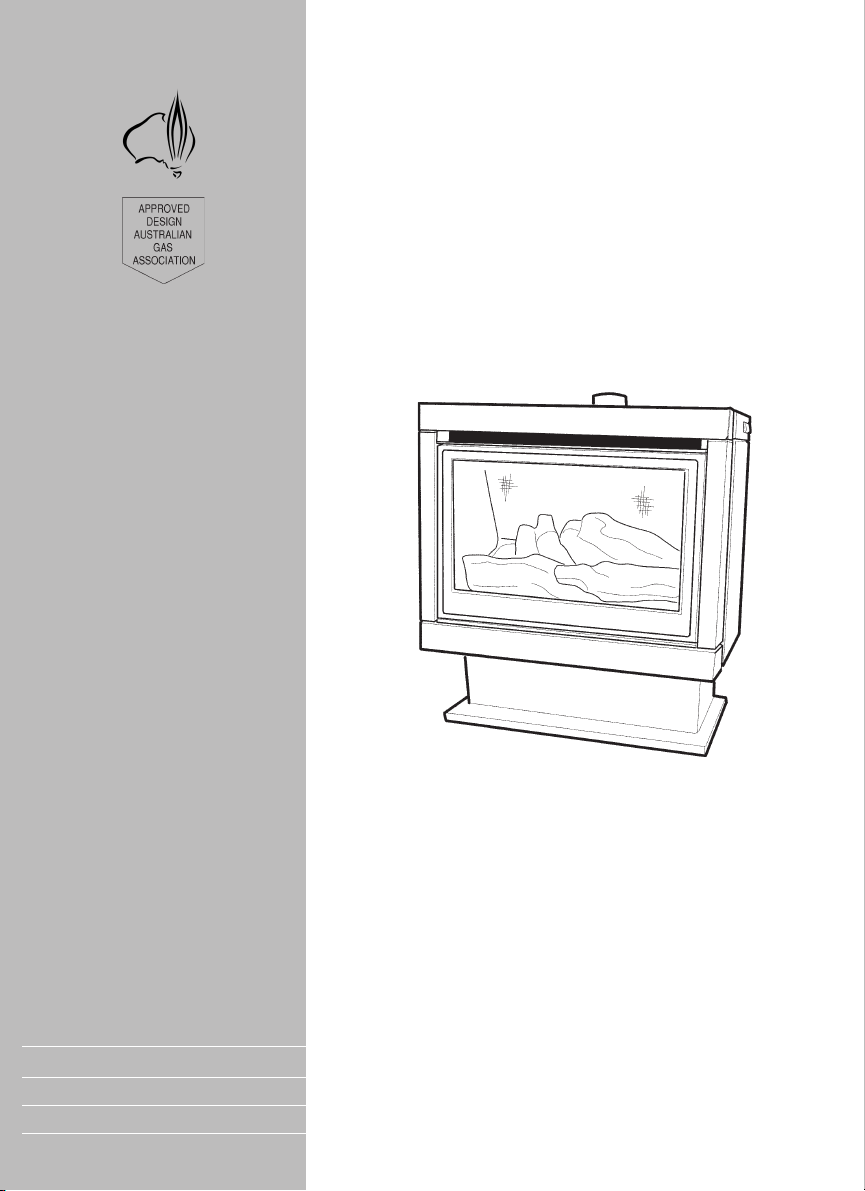
Cannon
FITZROY PROFILE
FREESTANDING MODELS
FITZP, FITZLP
USER INSTRUCTIONS
INSTALLATION INSTRUCTIONS
SERVICE INSTRUCTIONS
This heater is approved for use with Natural and Propane gases.
Please leave instructions with the owner
Page 2

Contents
Contents 2
Warranty 3
Safety warnings 4-5
❍ What to do if you smell gas
❍ Warnings
❍ Standards
User instructions 6-8
❍ Operating instructions
❍ Cleaning
Heater specifications 9
Installation instructions 10-15
❍ Clearances
❍ Installation
❍ Gas connection
❍ Fuel bed & log installation
❍ Gas control
❍ Gas pressure point
Flue installation 16-17
❍ Flue kit
Service instructions 18-19
❍ General
❍ Access to components
To replace the gas control
To replace the fan
To replace the electronic controller
To remove the burner and electrodes
❍ Wiring diagram
❍ Authorised service agents
Trouble shooting 20-21
❍ Connections
Notes 22-23
2
Page 3

Warranty
The Cannon appliance is warranted against defects in materials
and workmanship for a period of one, (1) year from its date of
original purchase, for residential use in Australia.
Warranty service, which includes parts and labour for the replacement or repair of defective parts, is available through Cannon
Authorised Service Agencies. (Please refer to the list of authorised
service agents in this manual.)
Consumers are responsible for service person’s travel outside normal service areas (approximately seventy (70k) radius from the
nearest Cannon dealer’s location), local cartage, and normal maintenance as described in this manual.
Any product subjected to misuse, abuse, negligence, accident or
alteration will have its warranty voided. The defacement of serial
plate will have its warranty voided.
If installation is not carried out in accordance with manufacturer’s
instructions, this warranty may be void.
The customer must keep their “Tax Invoice” as proof of purchase of
this product, and compliance certificate as proof of required installation.
Model number: ______________________________________
Serial number: _______________________________________
Date of manufacture: _________________________________
Date installed: _______________________________________
Compliance Certificate No: ____________________________
Don’t risk your appliance warranty
Only a licensed person will give you a Compliance Certificate, showing that the work complies with all the relevant
standards.
And only a licensed person will have insurance protecting
their workmanship for 6 years.
So make sure you use a licensed person to install this appliance and ask for your Compliance Certificate to ensure the
manufacturers appliance warranty will be honoured.
3
Page 4

Safety Warnings
Please read this manual before installing and using the heater.
What to do if you smell
gas
Warnings
1. Turn OFF the main gas supply.
2. Extinguish any open flame.
3. Open windows.
4. Do not touch electrical switches.
5. Do not use your telephone.
6. Call your gas supplier immediately from a neighbour’s phone.
1. Improper installation, adjustment, alteration, service or maintenance can cause injury or property damage. Refer to other
sections of this manual for correct procedures, or consult with
place of purchase, a licensed plumber, a gas supplier or
service agent listed in this manual.
2. Due to high temperatures the room heater should be located
out of traffic and away from:
• Furniture and draperies,
• Combustible materials,
• Gasoline and other flammable liquids,
Do not place clothing or other flammable material on or near
the heater.
3. Keep curtains*, clothing, furniture and other flammable materials at least 900mm from front, rear and sides of the heater.
* At the owner’s discretion curtain clearance can be less than
900mm as long as they are restrained from the front, top and
sides of the heater. The manufacturer takes no responsibility if
curtain clearance is less than 900mm and not restrained.
4. Children and adults should be alerted to the hazard of high
surface temperature and should take care to avoid burns or
clothing ignition.
Young children should be carefully supervised when they are
in the same room as the heater.
5. Never attempt to burn paper or any other material in the
heater.
6. Do not spray aerosols in the vicinity of this appliance while it
is in operation.
7. If removed the glass window must be put back onto the unit
prior to operating the heater.
8. Installation and repairs should be performed by a licensed
service person only, refer to back of brochure for service
number.
4
Page 5

Standards
9. The appliance should be inspected prior to use, with regular
inspections (annually) to be made by a licensed service person. It is important that circulating air passageways of the appliance be kept clean, dirt and lint free, for a safe and efficient
operation of the heater.
10. On first lighting your heater a smell may occur due to it’s new
condition. This is quite normal and will disappear after a few
hours use at the maximum control position.
Important:
WHEN THIS HEATER IS OPERATING, THE MESH GUARD IS
HOT.
The mesh guard fitted to the heater conforms to AGA requirements.
For heaters fitted with the optional glass front it should be noted that
THE GLASS FRONT IS HOT.
For permanent protection of young children or the infirm a secondary guard should be placed around the heater. A secondary guard
is not provided with this heater and may be purchased by the
owner.
This appliance meets the following standards:
Standards Australia: AS 3100
AS 5601/AG 601
AS 4553/AG 103
5
Page 6
User instructions
Operating instructions
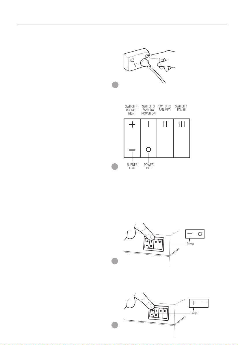
1. Plug the power cord into the wall socket and turn on the power
to the heater, see figure 1. Use of an extension cord is not
recommended
1
2. For control lay-out refer to figure 2
2
3. To turn heater on press switch to POWER ON position. There
is a 5 second delay before the burner ignites. At this setting the
burner is on LOW and the fan speed is on LOW. Refer
figure 3.
The burner will ignite on both HIGH and LOW settings.
3
4. To turn burner to HIGH setting, press switch for HIGH setting.
Refer figure 4.
4
6
Page 7
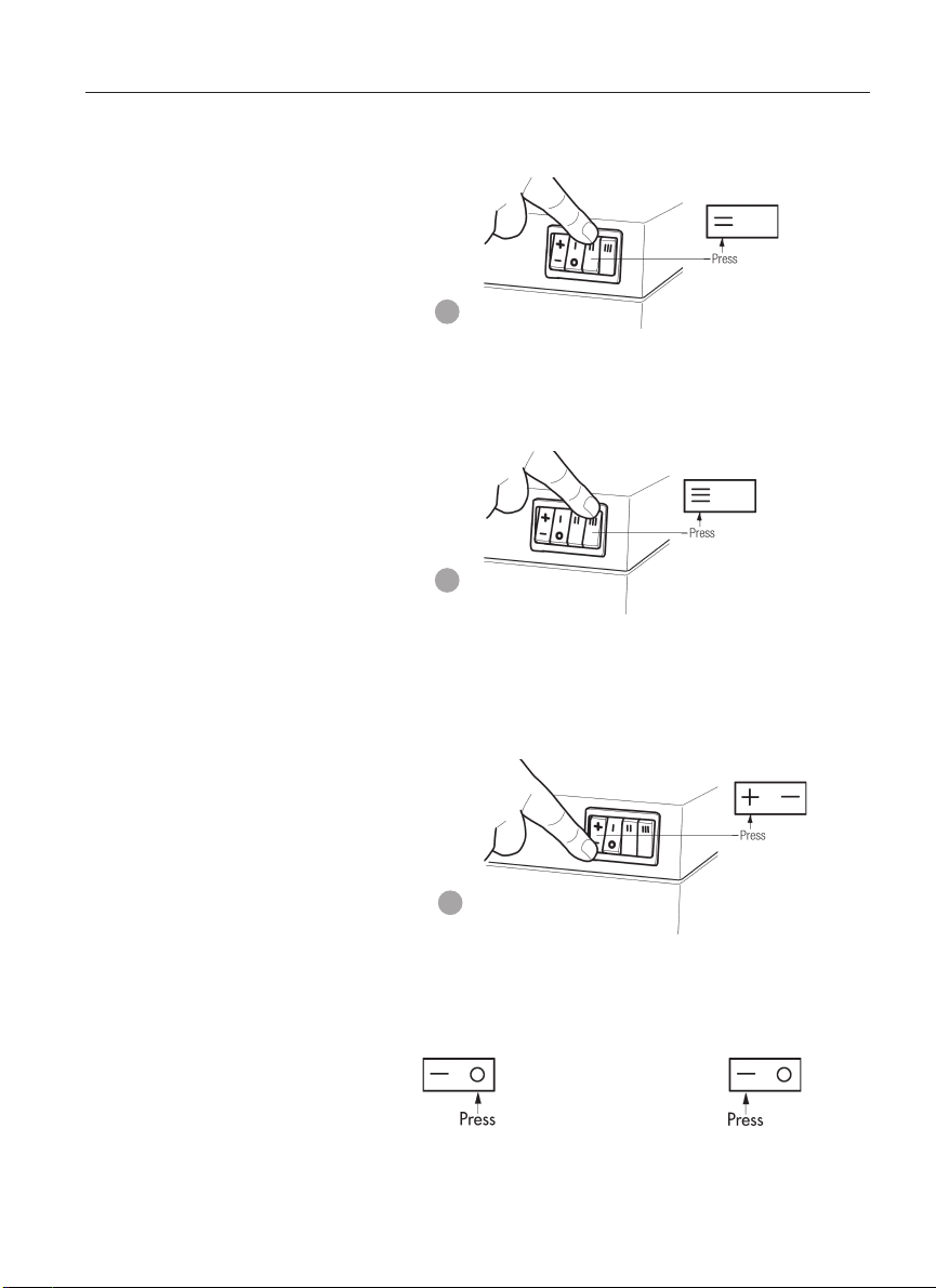
5. To increase the fan speed to MED, press switch for MED setting. Refer figure 5.
5
6. To increase the fan speed to HIGH, press switch for HIGH
setting. Refer figure 6.
6
7. To turn the burner to LOW setting, press switch for LOW setting. Refer figure 7.
On low burner setting it is more efficient to operate the fan
speed on LOW.
7
8. If the burner fails to ignite, wait 20 seconds and repeat the
ignition procedure. See below.
To turn burner OFF To turn burner ON
7
Page 8

User instructions continued
Cleaning.
All cleaning should be carried out when the heater is cold. Normally the heater should only need wiping with a lint - free damp
cloth. Any stubborn stains can be removed with a non-abrasive
spray on cleaner. If an abrasive cleaner is used the paint finish will
be damaged.
Internally the heater should only be cleaned by a licensed service
person listed in this manual.
If your heater requires attention contact your supplier or licensed
service person listed in this manual.
Important:
The appliance should be inspected before use and at least annually by an authorised service person. More frequent cleaning may
be required due to excessive lint build-up from carpeting, bedding
materials, pet hair, etc.
It is imperative that control compartments, burners and circulating
air passage ways of the appliance be kept clean.
Do not use this fire if the glass is cracked or with the glass safety
screen removed.
Do not use fire with broken or missing logs.
8
Page 9

Heater Specifications
Gas type: Natural or Propane gas, as indicated
Gas consumption: 26 M J/hr input
Energy star rating: 3.77
Energy output: 20.7 MJ/hr
Heater type: Heater approved to AG 103.
Operating pressure: Natural gas: 1.0 kPa
Min. inlet pressure: 1.20 kPa (NG)
Gas regulator: Integral with controller
Fan: Three speed
Controller: Electronic
Power requirement: 240 VAC 10 A
Optional Accessories: • Safety guard
Flue kit: 3 x 900mm lengths of 125mm ø
Overall dimensions: Refer fig. 8.
on data label
Propane gas: 2.65 kPa
For Propane gas regulated to supply
2.65 kPa
• Gold or silver trim
• Glass front
• Cathedral ceiling flue box
painted flue.
1 x 900mm length of 125mm ø
plain flue.
1 x ceiling ring.
1 x 900mm painted bottom flue
spigot length.
8
9
Page 10

Installation Instructions
1. This appliance is to be installed by a licensed service person
only.
2. This appliance is to be installed in accordance with the
manufacturer’s installation instructions, AS 5601/AG 601,
Municipal Building Codes, Electrical Wiring Regulations and
any other statutory regulations.
Clearances
3. Ensure the minimum clearances to combustible construction are
maintained during installation, including adequate space for
the proper operation and servicing of the heater.
For clearances to curtains and furnishing refer to warning 3 on
page 4.
For minimum clearances refer fig 9 and 10.
Installation
10
9
4. Remove the carton from the heater and lift from pallet.
Check that the heater is suitable for the gas available
(Please dispose of packaging appropriately, keep away from
children).
5. Prepare electrical and gas connections, a 10 Amp wall socket
needs to be located within 1.5m of the heater.
6. Fit rear spacers as per figure 10.
7. Place heater in position. (Check flue and gas connection positions. Refer to gas connection instructions on page 12 and flue
installation instructions on pages 14 & 15).
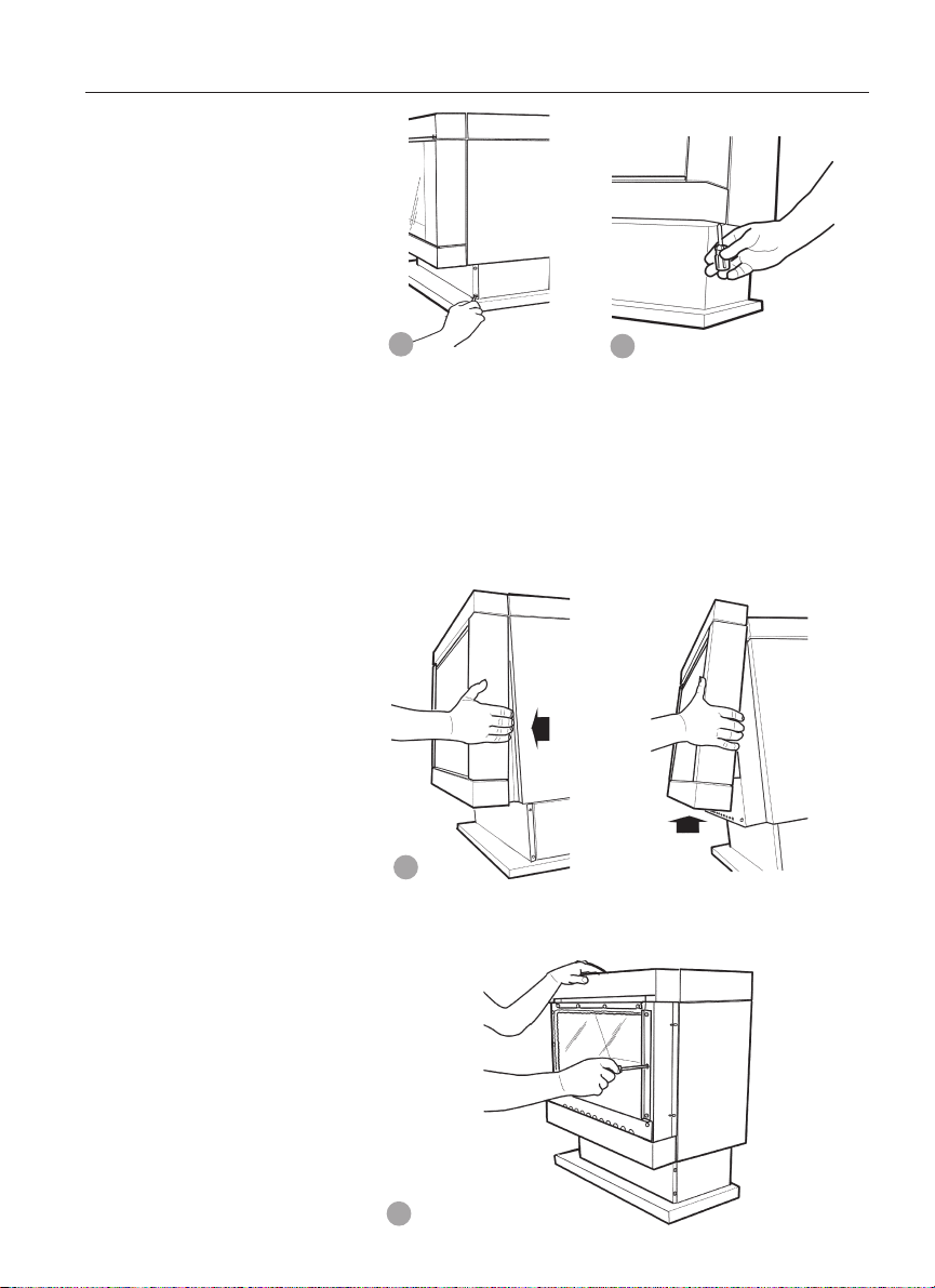
8. Remove the pedestal front by unscrewing two screws either
side. Refer figure 11.
10
Page 11
11
12
9. Remove the heater front securing screws, one either side. Refer figure 12.
10.Remove the heater front by pulling it towards you gently to
partly disengage it from the body of the heater then gently lift
it up vertically to completely disengage it. Refer figure 13.
13
11.Remove the inner glass. Slacken off screws in top clamp and
remove side clamps. Refer figure 14.
14
11
Page 12

Installation instructions continued
Gas connection
Fuel bed and log
installation
12. Connect incoming gas supply pipe at gas control inlet. The
inlet fitting is located 150mm in from the rear pedestal wall
RH side. Refer figure 15.
15
13. The fuel bed is contained within the burner chamber. Remove
the fuel bed transit packaging. Refer figure 16.
The fuel bed is retained by a spring clip fixed to the rear of the
burner chamber
FUEL BED MUST BE HARD UP AGAINST REAR OF BURNER
12
16
14. Carefully unpack the log set. Logs are numbered as follows:
No 1 - Left front log
No 2 - left back log
No 3 - Right front log
No 4 - Right back log
Position the four individually numbered logs in the following
order on the fuel bed as shown in figures 17-20. The male
locating pins in fuel bed must engage with corresponding
holes in the individual logs.
a) Place log No.1 onto the 2 front left pins on the fuel bed.
Refer figure 17.
17
Page 13

Gas control
b) Place log No.2 onto the 2 left back pins. Refer figure 18.
18
c) Place log No.3 on single right front pin, ensure fork
locates over log No. 2. Refer figure 19.
19
d) Place log No. 4 on single right back pin, ensure left side
of log rests on depression in No. 3 log. Refer figure 20.
20
15. Refit the inner glass, but do not overtighten the screws.
16. Refit the front glass surround. Ensure that the glass surround is
replaced the correct side up.
17. Gas control layout is as indicated in figure 21.
Pressures for ‘Burner full on’ and ‘Burner low flame’ are
factory set, however if pressures need to be checked or
adjusted follow the procedures described below and on
the next two pages.
21
13
Page 14
Installation instructions continued
To check control outlet pressure at burner ‘Full on” and ‘Low
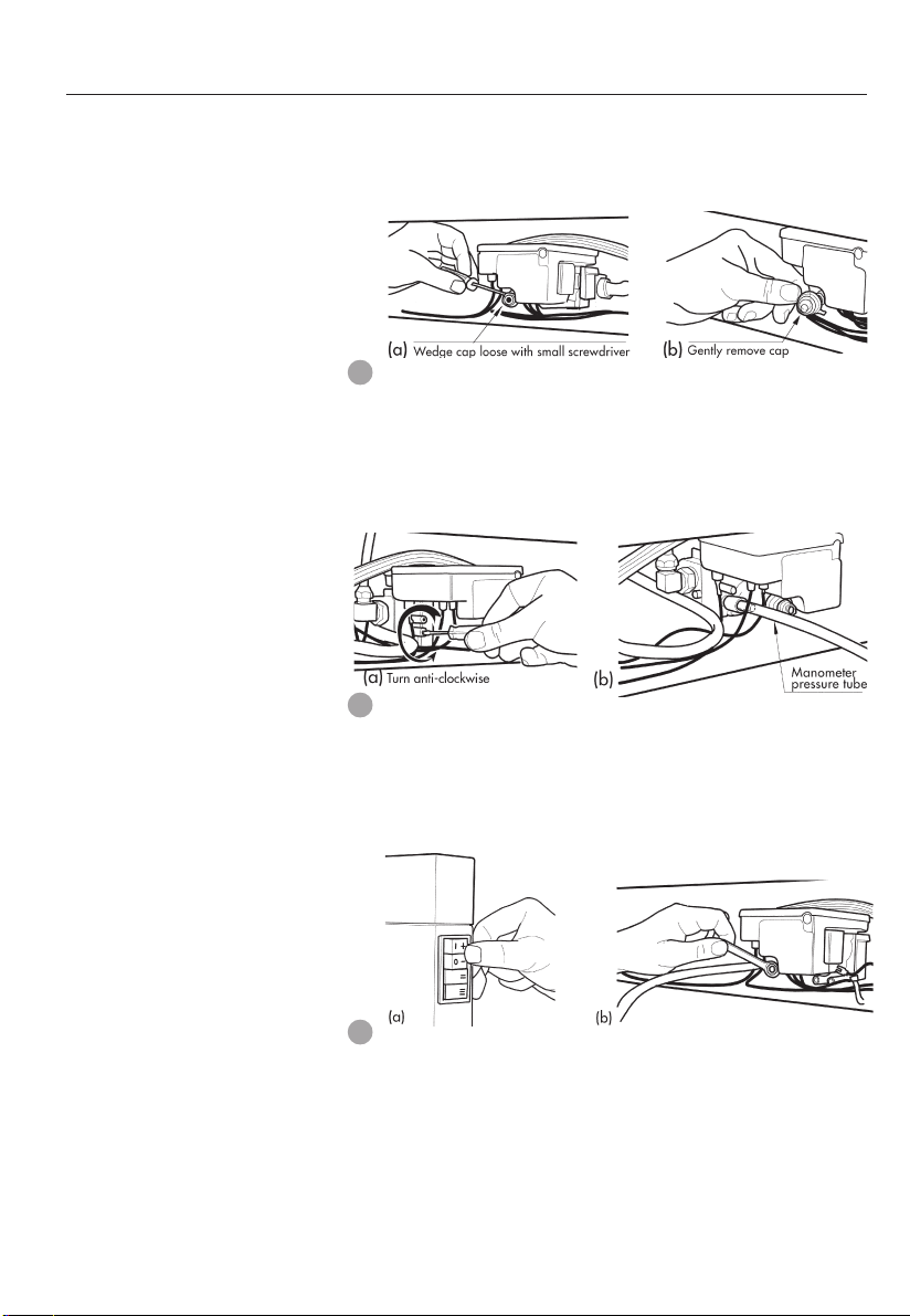
Flame” positions remove the plastic cap from the regulator
adjustment location as indicated in figures 22 (a) & (b).
22
Gas pressure point
18 The pressure point is closed with a captive screw. Turn screw
6 revolution anticlockwise to open the pressure point as indicated on figure 23 (a) and place manometer tube over the test
point as per figure 23 (b).
23
19. Switch the top two control buttons to “Full On” position as
indicated in figure 24(a) and using a ring spanner, as per
figure 24(b), adjust the pressure to 1kPa for Natural gas or
2.65 kPa for LPG. (Turn clockwise to increase pressure and
anticlockwise to decrease pressure).
24
14
20. Switch the stop button back to “Low Flame’ position as indicated in figure 25(a), retain spanner in position and using a
screwdriver as per figure 25(b) adjust the central screw control to give a pressure reading of 0.3 kPa for Natural Gas and
1.1 kPa for LPG. (Turn clock-wise to increase pressure and
anticlockwise to decrease pressure).
Page 15
25
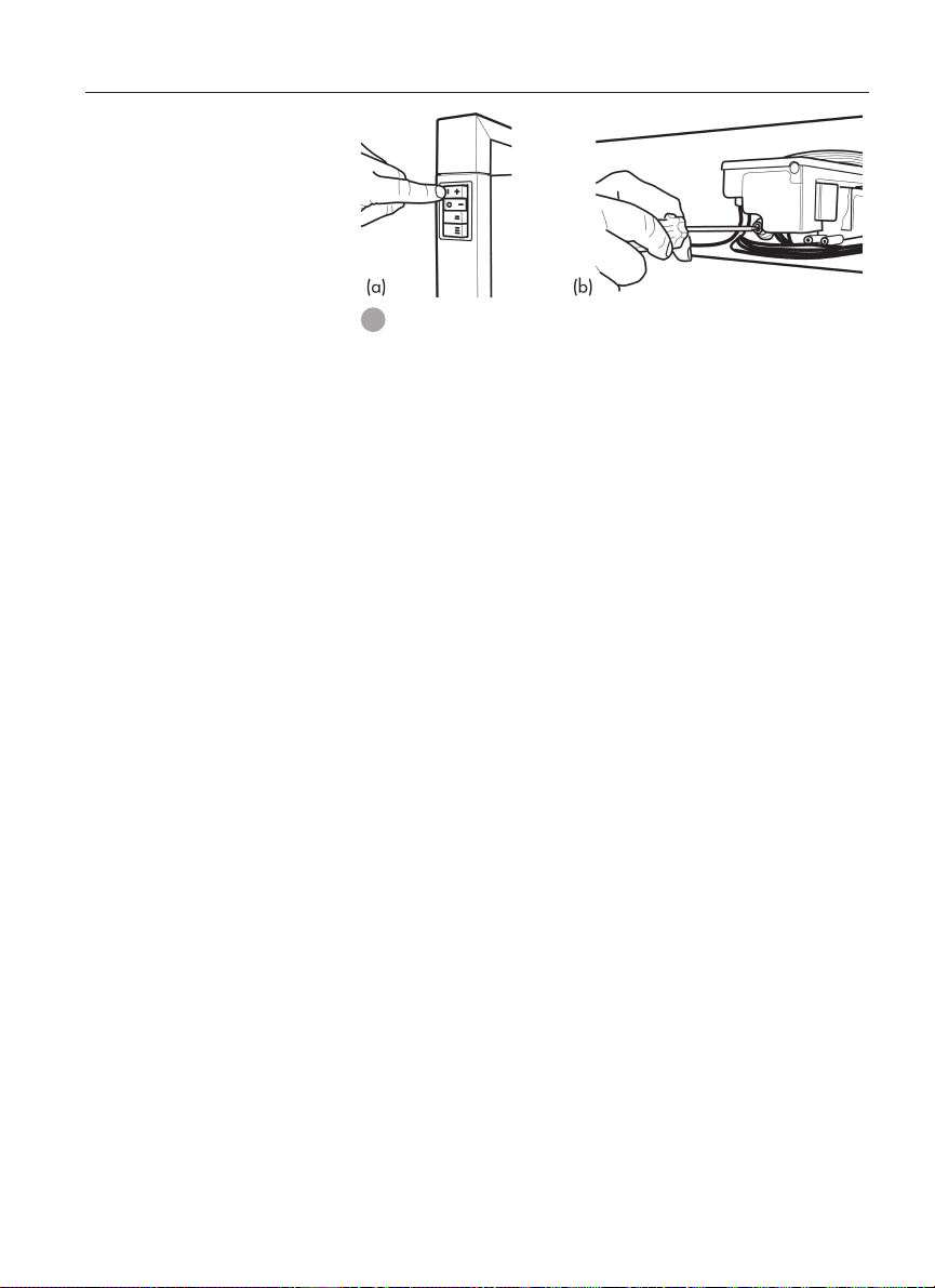
27. Switch burners off and remove the manometer tube. Tighten
pressure test point by turning the captive screw fully clockwise.
Replace plastic cap. Ensure the little lug is positioned towards
lower right hand side to clear the control.
28. Refit the lower front cover, making sure not to damage the
power cord.
29. Follow User Instructions to turn on heater.
Important:
To achieve the correct visual flame effect:
On Propane the gas pressure must be set at 2.65 kPa with burner
operating on maximum setting.
On Natural Gas the gas pressure must be set at 1.0 kPa.
15
Page 16
Flue installation
This heater is a flued appliance. It must be properly connected to a
flue system in accordance with the latest edition of the Gas Installation Code, AS 5601/AG 601.
If elbows are needed, the total horizontal length depends on the
number of elbows used. Venting should never slope down. A 6mm
per 500mm horizontal rise is recommended.
If practical locate the heater in a position to minimise the use of
horizontals and elbows.
The flue rise should be a minimum of 1.8m before any horizontal
run is used.
If placed against a combustible wall the 40mm rear spacers locate
against the wall.
1. Ensure clearances to combustible have been observed. For clearances refer page 10.
2. The centre line of the flue is 120mm to rear of appliance (including rear spacers).
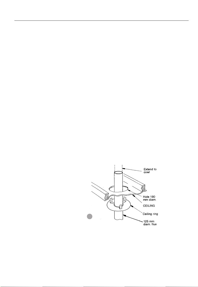
3. Carry out installation as per figure 26 (ceiling plate installation)
and figure 27 (flue installation).
Cut a hole 180mm ø in the ceiling in line with the flue position.
Secure ceiling plate against the ceiling by bending out the tabs
above the ceiling.
Note: If the ceiling has an incline, the ceiling box will need to
be fitted. Installation instructions are supplied with the ceiling
box.
20
Flue kit
16
26
The flue kit contains:
3 x 900mm lengths of 125mm ø painted flue.
1 x 900mm length of 125mm ø plain flue.
1 x ceiling plate
1 x 900mm painted bottom flue spigot.
Page 17

27
17
Page 18

Service Instructions
General
Access to components
1. Service work to be carried out by a licensed service person
only.
2. Unplug from wall socket.
3. Always shut off the gas supply and ensure that the heater is cool
before commencing any service operations.
4. Always check for gas soundness after servicing.
Remove the pedestal front by unscrewing two screws. Refer
figure 11.
To replace the gas control
1. Disconnect the gas regulator connector from the electronic
module.
2. Undo the inlet and outlet compression nuts.
3. Unscrew the four M3 retaining screws adjacent to the gas inlet
at the rear of the appliance, releasing the control.
4. Replace in reverse order.
To replace the fan
1. Disconnect the fan from the fan plug.
2. Undo the two M5 wing nuts fixing the fan to the burner chamber
underside.
3. Replace in reverse order.
To replace the electronic controller
1. Remove two screws from controller front.
2. Disconnect the plug.
3. Replace in the reverse order.
18
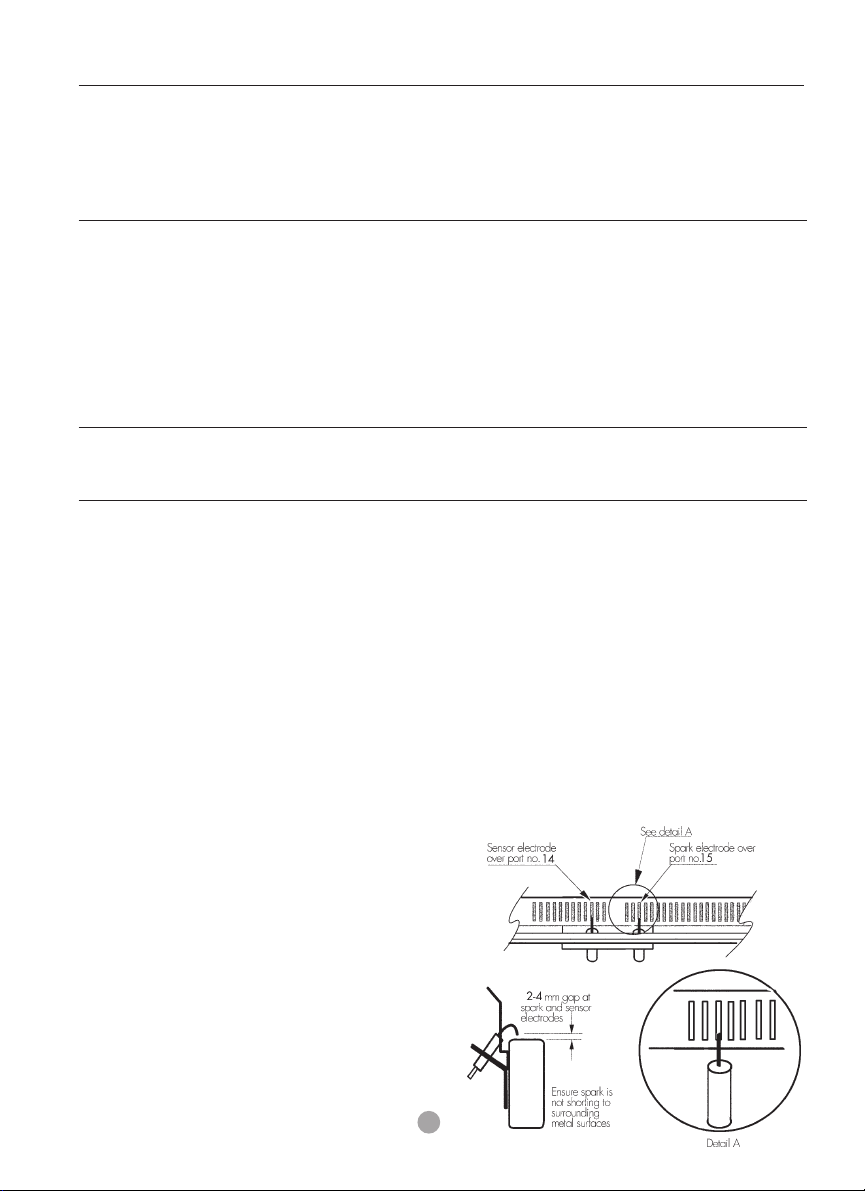
To remove the burner and electrodes
1. Follow steps 9 to 11 of the installation instructions.
2. Remove the logs and the fuel bed from the burner chamber.
3. Disconnect the compression nut at the back of the burner now
visible through the primary baffle.
4. Remove lower front panel.
5. Remove the four M5 screws fixing the burner chamber fascia in
position and disconnect the electrodes from the module.
6. Remove the two M5 screws fixing the burner to the burner chamber fascia.
7. Remove the two 8G self tapping screws fixing the electrodes in
position.
8. Replace in reverse order.
Page 19

Wiring diagram
Authorised service agents
For further information or spare parts contact the CANNON
distributor in your state.
Sampford & Staff Pty Ltd
421 Smith Street.
Fitzroy, Vic, 3065
Vic/Tas: (03) 9418 5800
NSW: (02) 9331 8888
SA/NT: (08) 8212 7000
Qld: (07) 3358 3000
WA: (08) 9242 5333
ACT: (02) 6280 4177
Elsewhere: 1800 334 887
email: service @sampford.com.au
19
Page 20

Troubleshooting
To check the operation of the electronic (module) controller (Type 537 ABC) you will require a digital
multimeter with the functions to measure AC/DC voltage, continuity, resistance and micro-amps.
It is critical that the appliance is earthed and that the active and neutrals are not reversed.
Item No Check Action
1 No ignition when appliance • Check 240 volts power to heater in incoming plug
2 Power present but appliance • If there is power to the brown wire in the 8 way
3 After resetting the module • Check the internal 3.5 amp fuse in the module.
4 If the fuse is O.K. and still • Check other connections are in place.
5 Confirm spark is produced • A blue spark can be seen when the heater ignition
6 If no spark being produced • Check that spark lead is connected into module.
is turned on. connector.
not operating. switch connector the module may be in lockout
and appliance is still not
operating.
appliance not operating • If the last checks are correct the ignition electrode
when heater is turned on. process starts. Ensure spark is present between
mode. To reset the module turn off the power supply
for 10 seconds and then turn the power on again.
should spark at the same time as the gas control
solenoid valves open. At this point the spark
electrode will activate for up to 10 seconds maxi
mum until the flame has been established. Terminal
14 (white wire into the 8 way switch connector)
will be energised as soon as the flame has been
sensed.
electrode and burner.
•
Check the continuity of the HT cable.
•
Check that there is no short circuit to earth and
spark gap is correct. (Refer figure 28). A positive
check is to use a jumper wire and connect one end
of the earth and hold the other end with insulated
pliers 4mm from the spark generator on the module.
If there is no spark to earth then change the module.
7 Spark is being produced • Listen for cracking sound. The spark is misdirected.
8 Sparks, ignites on low flame • Check that the wall socket to the appliance has
20
but not at burner. Check the spark ceramic insulator for signs of
cracks.
then extinguishes after 10 correct polarity. Do not use an extension cord. Check
seconds. Continues to spark polarity in the electrical supply lead to appliance.
during flame presence. • Check that the sense electrode is in the flame.
• Check that appliance is earthed correctly. A check
between the earth pin on the plug and an unpainted
part of the appliance should see a resistance of
0.1 ohms.
Page 21
9 No gas to burner. • The gas valve should open at the same time as the
igniter sparks. If there is no gas to the burner when
this occurs check the solenoid coils for continuity.
• Check that the gas pressure is present at the test
point when the spark is being generated.
• Check that there is gas to the inlet of the gas control.
10 Appliance lights but goes • Test the flame for correct ionisation signal. Connect a
into lockout. multimeter in series with the flame rod and set the
function to measure micro-amps. The module will go
into lockout if the flame current sensitivity is less than
0.5 micro-amps. The approximate signal strength on
high flame is about 10 micro-amps and on low
4 micro-amps. The signal strength will fluctuate but
should be greater than 1.5 micro-amps at all times.
Take precaution because the ionisation probe can
have a high negative voltage and can cause shock.
11 Fuse blowing. • If the fuse continues to blow check the solenoid coils
for signs of them being shorted.
• Check the fan is and wiring for short circuit.
Connections
Terminals 5, 6 and 7 at the module 12 way connector are bridged.
Terminal 10 at the module 12 way connector is the active supply
via the red wire.
Terminal 11 at the module 12 way connector is the neutral supply
via the blue wire.
Terminal 12 at the module 12 way connector is the earth connection via the green/yellow wire.
Terminal 12 at the module 2 way connector is the neutral connection via a brown wire which is joined into the rectifier cable then
into the 8 way switch connector blue wire.
Terminal 14 is an active connection at the module 2 way connector via a white wire into the 8 way switch connector. This is active
only when the flame is sensed.
28
21
Page 22

Notes
22
Page 23

Notes
23
Page 24

Cannon
FITZROY PROFILE
Part No: F2774
Revision C
 Loading...