

Canna Kit L298N Service Manual

UK1122
VERSION 1.0
L298 H-Bridge Dual Bidirectional
Motor Driver (2 x 2A)
This dual bidirectional motor driver is based on the very
popular L298 Dual H-Bridge Motor Driver Integrated Circuit.
The circuit will allow you to easily and independently control two
motors of up to 2A each in both directions.
It is ideal for robotic applications and well suited for
connection to a microcontroller requiring just a couple of control
lines per motor. It can also be interfaced with simple manual
switches, TTL logic gates, relays, etc.
The circuit incorporates 4 direction LEDs (2 per motor), a
heat sink, screw-terminals, as well as eight Schottky EMFprotection diodes. Two high-power current sense resistors are
also incorporated which allow monitoring of the current drawn
on each motor through your microcontroller.
Cana KitW
www.canakit.com
Manufacturer of High Quality Electronic Kits & Modules
4. To “coast” (i.e. let freely run) a particular motor, simply
set “ENA” or “ENB” to Low. When the enable of a
particular motor is set to Low, the corresponding motor
“coasts”.
5. The circuit also incorporates two current sense outputs,
“CSA” and “CSB” for each motor which expose the
corresponding current sense outputs of the L298 IC and
incorporate the required high-power resistors. You can
use these outputs to monitor the current draw of each
motor and detect stall conditions and take appropriate
action. For more information on how to use these, you
may refer to the L298 Datasheet which can be found at:
An onboard user-accessible 5V regulator is also
incorporated which can also be used to supply any additional
circuits requiring a regulated 5V DC supply of up to about 1A.
The circuit also offers a bridged mode of operation allowing
bidirectional control of a single motor of up to about 4A.
Operating Instructions
1. The circuit can be supplied in two different ways. Since
the circuit incorporates an onboard 5V DC regulator, the
required supply voltage for the operation of the L298
Integrated Circuit can be tapped off of the motor supply
voltage itself. Furthermore, this 5V DC regulated voltage
is also available for any other circuitry you may want to
drive. The jumper setting and wiring diagram for this way
of supplying the circuit is indicated in Wiring Diagram 1.
This is the recommended way of supplying the
circuit.
Alternatively, if you would like to keep the motor supply
voltage completely independent and isolated from the
L298 5V supply voltage, then you would need to provide
your own 5V DC regulated voltage to supply the L298 IC.
The jumper setting and wiring diagram for this way of
supplying the circuit is indicated in Wiring Diagram 2.
2. Each motor is controlled by setting to High “ENA” or
“ENB” for the corresponding motor. You can then
control the direction of each motor by enabling “IN1” or
“IN2” for motor “A” and “IN3” or “IN4” for motor “B”.
3. To “brake” a particular motor, you will need to set “ENA”
or “ENB” to High and then set both direction pins to either
High or Low.
http://www.canakit.com/Media/Datasheets/L298.pdf
Manufactured by:
Cana Kit Corporation
#118 – 2455 Dollarton Highway
North Vancouver • BC • V7H 0A2 • Canada
Tel: (604) 298-3305 • Fax: (604) 298-3390
Email: info@canakit.com
Web Site: www.canakit.com
Copyright © 1990 – 2010 Cana Kit Corporation
Reproduction without prior written permission is strictly prohibited
All rights reserved
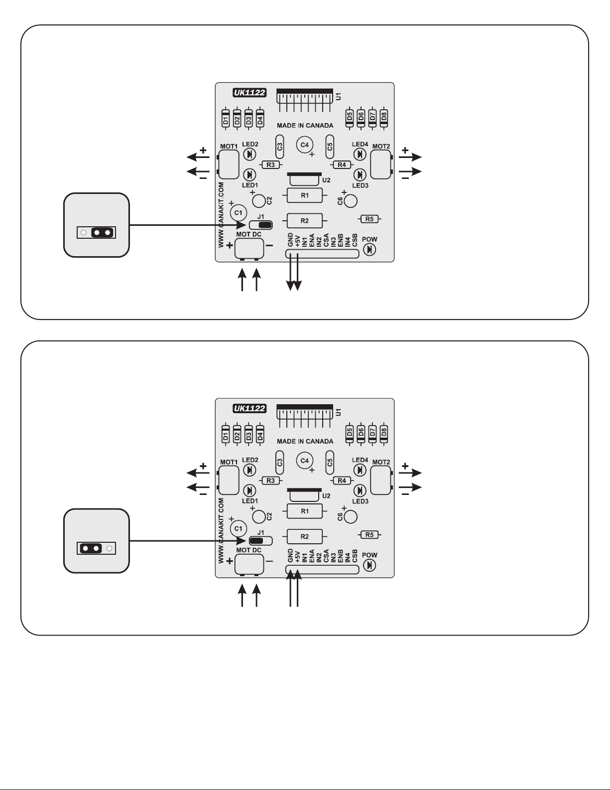
USING THE MOTOR SUPPLY VOLTAGE FOR THE L298 SUPPLY VOLTAGE (RECOMMENDED)
J1
MOTOR “A”
6 – 35V DC
5V DC
OUTPUT
MOTOR “B”
USING AN INDEPENDENT SUPPLY VOLTAGE FOR L298 SUPPLY VOLTAGE
(NOTE: IN THIS MODE THE ONBOARD 5V DC REGULATOR IS DISABLED)
Wiring Diagram 1
J1
MOTOR “A”
6 – 35V DC 5V DC
INPUT
Manufactured by:
Cana Kit Corporation
(Unikit is a division of Cana Kit Corporation)
#118 – 2455 Dollarton Highway
North Vancouver • BC • V7H 0A2 • Canada
Tel: (604) 298-3305 • Fax: (604) 298-3390
Email: info@canakit.com
Web Site: www.canakit.com
MOTOR “B”
Wiring Diagram 2
 Loading...