

Page 1
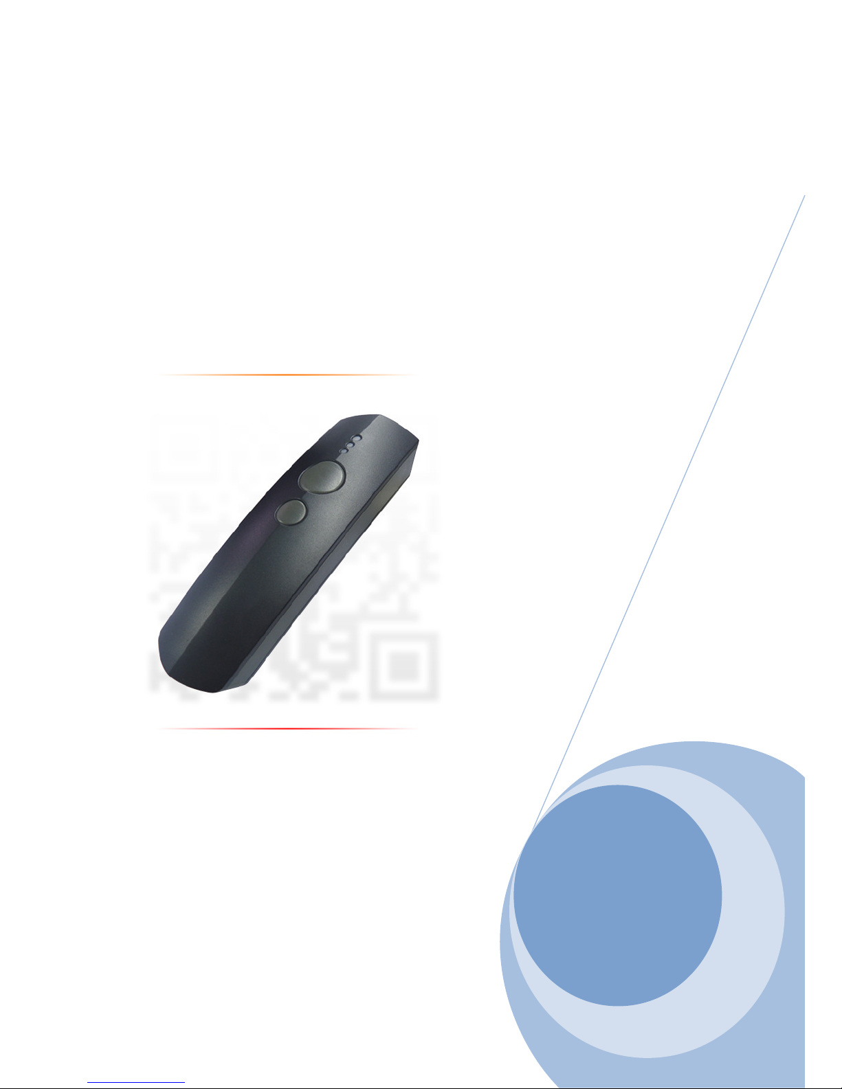
2D Bluetooth Barcode
Scanner User manual.
Version: 1.2
Copyright© May.3.2018 All rights reserved
Page 2

2
Index
Chapter 1: Import Notice ............................................................................. 19
1-1 Regulations ..................................................................................... 20
1-2 TECHNICAL REGULATIONS CONFORMITY FOR SPECIFIED
RADIO EQUIPMENT IN JAPAN ..................................................... 20
1-3 NATIONAL COMMUNICATION COMMISSION .............................. 21
1-4 RoHS DIRECTIVE ........................................................................... 21
1-5 SAFETY PRECAUTION .................................................................. 22
Chapter 2: Introduction ............................................................................... 23
2-1 PRODUCT FEATURES ................................................................... 24
2-2 PRODUCT SPECIFICATION ........................................................... 25
2-3 PACKAGE INFORMATION ............................................................. 27
2-4 DEFAULT SYMBOLOGIES ............................................................. 28
2-5 FUNCTION KEYS AND LED INDICATOR ...................................... 30
Chapter 3: Scanner Configuration .............................................................. 31
3-1 Configuration by USER MANUAL ................................................. 32
3-2 Configuration by SOFTWARE ....................................................... 33
Chapter 4 Memory / Bluetooth Mode .......................................................... 34
4-1 Memory Mode ................................................................................. 35
4-1-1 Function switch (Bluetooth mode to Memory mode) ........... 35
4-1-2 Transmitting barcode data in memory mode ....................... 35
4-1-3 Erase barcode data (Single data/ All data) .......................... 36
4-2 Bluetooth Mode .............................................................................. 37
4-2-1 Function switch (Memory Mode to Bluetooth mode) ........... 37
4-2-2 LED indication under Bluetooth Mode ................................ 38
4-2-3 Bluetooth mode selection Code Table ................................ 39
4-2-4 Bluetooth mode configuration by user manual .................... 40
4-2-4-1 Slave Mode : Third party Bluetooth devices ( Mode
selection code: 1) .................................................. 40
4-2-4-2 Master Mode - Third party Bluetooth devices (Mode
selection code: 2) .................................................. 40
4-2-4-3 HID Mode - Third party Bluetooth devices (Mode
selection code: 3) .................................................. 41
4-2-4-4 iOS MODE (Mode selection code : 4) ................... 41
4-2-4-5 A-303 dongle Mode (Mode selection code: 5) ....... 42
4-2-4-6 A-302 dongle Mode (Mode selection code: 6) ....... 42
4-2-5 Bluetooth parameter configuration by user manual ............ 43
4-2-5-1 BT Local name ...................................................... 43
4-2-5-2 Remote Mac Address ........................................... 44
4-2-5-3 Pin Code ............................................................... 46
Page 3

3
Index
Chapter 5: Bluetooth Connection Mode Instruction ................................. 47
5-1 Slave mode Connection (For Third party Bluetooth devices) ..... 48
5-2 Master mode Connection (For Third party Bluetooth Devices) . 53
5-3 HID mode Connection (For Third party Bluetooth devices) ....... 58
5-4 iOS mode Connection .................................................................... 61
5-5 A-303 Dongle mode Connection(USB-HID / USB COM) .............. 65
5-5-1 HID mode............................................................................ 65
5-5-2 USB-COM mode ................................................................. 66
5-6 A-302 Dongle mode connection (USB-HID only) ......................... 68
Chapter 6: Memory / Bluetooth / Cable General Setting ........................... 69
6-1 General Memory Mode Setting ..................................................... 73
6-1-1 Mode ................................................................................... 73
6-1-2 Output Interface .................................................................. 74
6-1-3 App Type ……………………………………………………….74
6-1-4 Composite Triggers Functionality ........................................ 75
6-1-5 Small Trigger Functionality .................................................. 75
6-1-6 Dcplug Charge .................................................................... 76
6-1-7 GoodRead Beep Volume .................................................... 76
6-1-8 Event Beep Volume ............................................................ 77
6-1-9 Warning Beep Volume ........................................................ 77
6-1-10 Tx Style ............................................................................. 78
6-1-11 Tx PostProc ...................................................................... 78
6-1-12 Tx Header ......................................................................... 79
6-1-13 Tx Footer .......................................................................... 79
6-1-14 GoodRead Vibrator ........................................................... 79
6-1-15 Event Vibrator ................................................................... 80
6-1-16 Warning Vibrator ............................................................... 80
6-1-17 Scan Time ......................................................................... 81
6-1-18 Scan Idle Time .................................................................. 82
6-1-19 StandbyTime ..................................................................... 83
6-1-20 Tx Preamble ..................................................................... 83
6-1-21 Preamble data .................................................................. 84
6-1-22 Tx Postamble .................................................................... 84
6-1-23 Postamble data ................................................................. 85
6-1-24 Tx Prefix ............................................................................ 85
6-1-25 Prefix data ......................................................................... 86
6-1-26 Tx Suffix ............................................................................ 86
6-1-27 Suffix data ......................................................................... 87
6-1-28 Tx CodeName ................................................................... 87
6-1-29 Tx CodeId ......................................................................... 88
Page 4

4
Index
6-1-30 CodeId Position ................................................................ 88
6-1-31 Tx Code Length ................................................................ 88
6-1-32 ForceCase ........................................................................ 89
6-1-33 Tx Delimiter ....................................................................... 89
6-1-34 DelimiterChar .................................................................... 90
6-1-35 Tx Control Code ................................................................ 90
6-1-36 WaitKeyTime .................................................................... 91
6-1-37 Date & Time Transmission ................................................ 91
6-1-38 Date/Time Position ........................................................... 92
6-1-39 DateTimeSpareChar ......................................................... 92
6-1-40 Reject Same ..................................................................... 92
6-2 General Bluetooth Mode Setting................................................... 93
6-2-1 Mode ................................................................................... 93
6-2-2 Output Interface .................................................................. 94
6-2-3 App Type ……………………………………………………… 94
6-2-4 Composite Triggers Functionality ........................................ 95
6-2-5 Small Trigger Functionality .................................................. 95
6-2-6 Dcplug Charge .................................................................... 96
6-2-7 GoodRead Beep Volume .................................................... 96
6-2-8 Event Beep Volume ............................................................ 97
6-2-9 Warning Beep Volume ........................................................ 97
6-2-10 GoodRead Vibrator ........................................................... 98
6-2-11 Event Vibrator ................................................................... 98
6-2-12 Warning Vibrator ............................................................... 98
6-2-13 Pairing Time ...................................................................... 99
6-2-14 Good Read Beep Freq .................................................... 100
6-2-15 Good Read Beep Time ................................................... 101
6-2-16 Good Read Vibrator time ................................................ 102
6-2-17 Scan Time ....................................................................... 103
6-2-18 Scan Idle Time ................................................................ 104
6-2-19 StandbyTime ................................................................... 105
6-2-20 Tx Preamble ................................................................... 105
6-2-21 Preamble data ................................................................ 106
6-2-22 Tx Postamble .................................................................. 106
6-2-23 Postamble data ............................................................... 107
6-2-24 Tx Prefix .......................................................................... 107
6-2-25 Prefix data ....................................................................... 108
6-2-26 Tx Suffix .......................................................................... 108
6-2-27 Suffix data ....................................................................... 109
6-2-28 Tx CodeName ................................................................. 109
Page 5

5
Index
6-2-29 Tx CodeId ....................................................................... 110
6-2-30 CodeId Position .............................................................. 110
6-2-31 Tx Code Length .............................................................. 110
6-2-32 ForceCase ...................................................................... 111
6-2-33 Tx Delimiter ..................................................................... 111
6-2-34 DelimiterChar .................................................................. 112
6-2-35 Tx Control Code .............................................................. 112
6-2-36 Date & Time Transmission .............................................. 113
6-2-37 Date/Time Position ......................................................... 113
6-2-38 DateTimeSpareChar ....................................................... 114
6-3 General Cable Mode Setting ....................................................... 115
6-3-1 Mode ................................................................................. 115
6-3-2 Output Interface ................................................................ 116
6-3-3 App Type ........................................................................... 116
6-3-4 Composite Triggers Functionality ...................................... 117
6-3-5 Small Trigger Functionality ................................................ 117
6-3-6 Dcplug Charge .................................................................. 118
6-3-7 GoodRead Beep Volume .................................................. 118
6-3-8 Event Beep Volume .......................................................... 119
6-3-9 Warning Beep Volume ...................................................... 119
6-3-10 GoodRead Vibrator ......................................................... 120
6-3-11 Event Vibrator ................................................................. 120
6-3-12 Warning Vibrator ............................................................. 120
6-3-13 Power on light ................................................................. 121
6-3-14 Good Read Beep Freq .................................................... 121
6-3-15 Good Read Beep Time ................................................... 122
6-3-16 Good Read Vibrator time ................................................ 122
6-3-17 Scan Time ....................................................................... 123
6-3-18 Tx Preamble ................................................................... 124
6-3-19 Preamble data ................................................................ 124
6-3-20 Tx Postamble .................................................................. 125
6-3-21 Postamble data ............................................................... 125
6-3-22 Tx Prefix .......................................................................... 126
6-3-23 Prefix data ....................................................................... 126
6-3-24 Tx Suffix .......................................................................... 127
6-3-25 Suffix data ....................................................................... 127
6-3-26 Tx CodeName ................................................................. 128
6-3-27 Tx CodeId ....................................................................... 128
6-3-28 CodeId Position .............................................................. 128
6-3-29 Tx Code Length .............................................................. 129
Page 6

6
Index
6-3-30 ForceCase ...................................................................... 129
6-3-31 Tx Delimiter ..................................................................... 130
6-3-32 DelimiterChar .................................................................. 130
6-3-33 Tx Control Code .............................................................. 131
6-3-34 Date & Time Transmission .............................................. 131
6-3-35 Date/Time Position ......................................................... 131
6-3-36 DateTimeSpareChar ....................................................... 132
6-4 Scanner Confuguration by Software .......................................... 133
6-4-1 Firmware Update .............................................................. 133
6-4-2 Scanner Configuration ...................................................... 137
Chapter 7: General configuration setting ................................................ 141
7-1 Host Interface ............................................................................... 144
7-1-1 Version .............................................................................. 144
7-1-2 Abort Setting ..................................................................... 144
7-1-3 Enter ISP Mode ................................................................ 145
7-1-4 Barcode Default ................................................................ 145
7-1-5 All Default ......................................................................... 145
7-1-6 Mode Switch ..................................................................... 146
7-2 Output Interface ........................................................................... 147
Cable Mode ......................................................................................... 147
7-2-1 USB-HID Keyboard Type ................................................ 148
7-2-1-1 Caps Lock .................................................................. 148
7-2-1-2 Num Lock ................................................................... 148
7-2-1-3 Shift Release Caps Lock ............................................ 149
7-2-1-4 Transmission Timeout ................................................ 149
7-2-1-5 Transmission Char Delay ........................................... 150
7-2-1-6 Transmission Char Gap Time ..................................... 150
7-2-1-7 Transmission Record Gap Time ................................. 151
7-2-1-8 USB HID Layout Setting............................................. 151
7-2-1-9 Output Language ....................................................... 152
7-2-2 USB-SPP(Virtual COM) Type .......................................... 153
7-2-2-1 Communication Protocol ............................................ 153
7-2-2-2 <STX> & <ETX> Characters ...................................... 153
7-2-2-3 <CMD> & <BAR> Characters .................................... 154
7-2-2-4 Command Mode ........................................................ 154
7-2-2-5 Retransmission Count ................................................ 155
7-2-2-6 ACK Timeout .............................................................. 155
7-2-2-7 Transmission Timeout ................................................ 156
7-2-2-8 Transmission Char Delay ........................................... 156
7-2-2-9 Transmission Char Gap Time ..................................... 157
Page 7

7
Index
7-2-2-10 Transmission Record Gap Time ............................... 157
Bluetooth Mode .................................................................................. 158
7-2-3 Bluetooth HID Type ......................................................... 158
7-2-3-1 Caps lock ................................................................... 158
7-2-3-2 Num Lock ................................................................... 158
7-2-3-3 Shift Release Caps Lock ............................................ 159
7-2-3-4 Bluetooth HID Layout Settiing .................................... 159
7-2-3-5 Transmission Timeout ................................................ 160
7-2-3-6 Transmission Char Delay ........................................... 160
7-2-3-7 Transmission Char Gap Time ..................................... 161
7-2-3-8 Transmission Record Gap Time ................................. 161
7-2-3-9 Output Language ....................................................... 162
7-2-4 Bluetooth-SPP Type........................................................ 163
7-2-4-1 Communication Protocol ............................................ 163
7-2-4-2 <STX> & <ETX> Characters ...................................... 163
7-2-4-3 <CMD> & <BAR> Characters .................................... 164
7-2-4-4 Command Mode ........................................................ 164
7-2-4-5 Retransmission Count ................................................ 165
7-2-4-6 ACK Timeout .............................................................. 165
7-2-4-7 Transmission Timeout ................................................ 166
7-2-4-8 Transmission Char Delay ........................................... 166
7-2-4-9 Transmission Char Gap Time ..................................... 167
7-2-4-10 Transmission Record Gap Time .............................. 167
Memory Mode ..................................................................................... 168
7-2-5 Memory HID Type............................................................ 168
7-2-5-1 Caps lock ................................................................... 168
7-2-5-2 Num Lock ................................................................... 168
7-2-5-3 Shift Release Caps Lock ............................................ 169
7-2-5-4 Memory HID Layout Settiing ...................................... 169
7-2-5-5 Transmission Timeout ................................................ 170
7-2-5-6 Transmission Char Delay ........................................... 170
7-2-5-7 Transmission Char Gap Time ..................................... 171
7-2-5-8 Transmission Record Gap Time ................................. 171
7-2-5-9 Output Language ....................................................... 172
7-2-6 Memory-SPP Type .......................................................... 173
7-2-6-1 Communication Protocol ............................................ 173
7-2-6-2 <STX> & <ETX> Characters ...................................... 173
7-2-6-3 <CMD> & <BAR> Characters .................................... 174
7-2-6-4 Retransmission Count ................................................ 174
7-2-6-5 ACK Timeout .............................................................. 175
Page 8

8
Index
7-2-6-6 Transmission Timeout ................................................ 175
7-2-6-7 Transmission Char Delay ........................................... 176
7-2-6-8 Transmission Char Gap Time ..................................... 176
7-2-6-9 Transmission Record Gap Time ................................. 177
7-3 System Control............................................................................. 178
7-3-1 Mode ................................................................................. 178
7-3-2 System Beep Volume ....................................................... 178
7-3-3 DcPlug Cable Mode .......................................................... 179
7-3-4 Date format ....................................................................... 180
7-3-5 Time format ....................................................................... 180
7-3-6 System Virbator ................................................................ 181
7-3-7 Show Header Str .............................................................. 181
7-3-8 Show Footer Str ................................................................ 181
7-3-9 Show Header SerNum ...................................................... 182
7-3-10 Show Footer SerNum ................................................... 182
7-3-11 Show Header Date & Time ............................................. 182
7-3-12 Show Footer Date & Time ............................................... 183
7-3-13 Show Header RecCnt ..................................................... 183
7-3-14 Show Footer RecCnt ...................................................... 183
7-3-15 Date Separator ............................................................... 184
7-3-16 Time Separator ............................................................... 184
7-3-17 DLE Escape Characters ................................................. 185
7-3-18 CMD Escape Characters ................................................ 185
7-3-19 BAR Escape Characters ................................................. 186
7-3-20 ETX Escape Characters ................................................. 186
7-3-21 STX Escape Characters ................................................. 187
7-3-22 Setup Timeout Time ........................................................ 187
7-3-23 Set Date & Time ............................................................. 188
7-3-24 All Memory Data Clear .................................................... 188
7-3-25 All Memory Data Transmission ....................................... 189
7-3-26 Footer Chatacters ........................................................... 189
7-3-27 Header Chatacters .......................................................... 190
Chapter 8: Symbology Settings ................................................................ 191
8-1 Barcode Symbologies Default Setting Chart ............................. 192
8-2 UPC-A ............................................................................................ 194
8-2-1 Read ................................................................................. 194
8-2-2 CheckDigit ........................................................................ 194
8-2-3 Addon2 ............................................................................. 194
8-2-4 Addon5 ............................................................................. 195
8-2-5 Wait Add-on ...................................................................... 195
Page 9

9
Index
8-2-6 Addon Separator ............................................................... 195
8-2-7 Coupon Gs1DataBar Output ............................................. 196
8-2-8 ExtendedCouponCode ..................................................... 196
8-2-9 Wait Addon Time .............................................................. 197
8-2-10 ConvertUpcaToEan13 ..................................................... 197
8-2-11 TruncateLeading ............................................................. 198
8-2-12 TruncateEnding ............................................................... 198
8-2-13 TruncateZero .................................................................. 199
8-2-14 Insertion1DataPosition .................................................... 199
8-2-15 Insertion1Data ................................................................ 200
8-2-16 Insertion2DataPosition .................................................... 200
8-2-17 Insertion2Data ................................................................ 201
8-3 UPC-E ............................................................................................ 202
8-3-1 Read ................................................................................. 202
8-3-2 Expansion ......................................................................... 202
8-3-3 CheckDigit ........................................................................ 203
8-3-4 Addon2 ............................................................................. 203
8-3-5 Addon5 ............................................................................. 203
8-3-6 Wait addon ........................................................................ 204
8-3-7 Addon Separator ............................................................... 204
8-3-8 Wait Addon Time .............................................................. 205
8-3-9 TruncateLeading ............................................................... 205
8-3-10 TruncateEnding ............................................................... 206
8-3-11 TruncateZero ................................................................... 206
8-3-12 Insertion1DataPosition .................................................... 207
8-3-13 Insertion1Data ................................................................ 207
8-3-14 Insertion2DataPosition .................................................... 208
8-3-15 Insertion2Data ................................................................ 208
8-4 EAN-13 .......................................................................................... 209
8-4-1 Read ................................................................................. 209
8-4-2 CheckDigit ........................................................................ 209
8-4-3 Addon2 ............................................................................. 209
8-4-4 Addon5 ............................................................................. 210
8-4-5 Wait addon ........................................................................ 210
8-4-6 Addon Separator ............................................................... 210
8-4-7 ISBN Conversion .............................................................. 211
8-4-8 Wait Addon Time .............................................................. 211
8-4-9 TruncateLeading ............................................................... 212
8-4-10 TruncateEnding ............................................................... 212
8-4-11 TruncateZero ................................................................... 213
Page 10

10
Index
8-4-12 Insertion1DataPosition .................................................... 213
8-4-13 Insertion1Data ................................................................ 214
8-4-14 Insertion2DataPosition .................................................... 214
8-4-15 Insertion2Data ................................................................ 215
8-5 EAN-8 ............................................................................................ 216
8-5-1 Read ................................................................................. 216
8-5-2 CheckDigit ........................................................................ 216
8-5-3 Addon2 ............................................................................. 216
8-5-4 Addon5 ............................................................................. 217
8-5-5 Wait addon ........................................................................ 217
8-5-6 Addon Separator ............................................................... 217
8-5-7 Wait Addon Time .............................................................. 218
8-5-8 TruncateLeading ............................................................... 218
8-5-9 TruncateEnding ................................................................. 219
8-5-10 TruncateZero .................................................................. 219
8-5-11 Insertion1DataPosition .................................................... 220
8-5-12 Insertion1Data ................................................................ 220
8-5-13 Insertion2DataPosition .................................................... 221
8-5-14 Insertion2Data ................................................................ 221
8-6 Msi ................................................................................................. 222
8-6-1 Read ................................................................................. 222
8-6-2 Chksum Verification .......................................................... 222
8-6-3 Min Code Length .............................................................. 223
8-6-4 Max Code Length ............................................................. 223
8-6-5 TruncateLeading ............................................................... 224
8-6-6 TruncateEnding ................................................................. 224
8-6-7 TruncateZero .................................................................... 225
8-6-8 Insertion1DataPosition ...................................................... 225
8-6-9 Insertion1Data .................................................................. 226
8-6-10 Insertion2DataPosition .................................................... 226
8-6-11 Insertion2Data ................................................................. 227
8-7 Gs1 Databar .................................................................................. 228
8-7-1 OmnidirectionalRead ........................................................ 228
8-7-2 LimitedRead...................................................................... 228
8-7-3 Expanded Read ................................................................ 229
8-7-4 Min Code Length .............................................................. 229
8-7-5 Max Code Length ............................................................. 230
8-7-6 TruncateLeading ............................................................... 231
8-7-7 TruncateEnding ................................................................. 232
8-7-8 TruncateZero .................................................................... 233
Page 11

11
Index
8-7-9 Insertion1DataPosition ...................................................... 234
8-7-10 Insertion1Data ................................................................ 235
8-7-11 Insertion2DataPosition .................................................... 236
8-7-12 Insertion2Data ................................................................ 237
8-8 Gs1 Composite ............................................................................. 238
8-8-1 Read ................................................................................. 238
8-8-2 Upc/EanVersion ................................................................ 238
8-8-3 Gs1Emulation ................................................................... 239
8-8-4 Min Code Length .............................................................. 240
8-8-5 Max Code Length ............................................................. 240
8-8-6 TruncateLeading ............................................................... 241
8-8-7 TruncateEnding ................................................................. 241
8-8-8 TruncateZero .................................................................... 242
8-8-9 Insertion1DataPosition ...................................................... 242
8-8-10 Insertion1Data ................................................................ 243
8-8-11 Insertion2DataPosition .................................................... 243
8-8-12 Insertion2Data ................................................................ 244
8-9 Codablock ..................................................................................... 245
8-9-1 CodablockARead .............................................................. 245
8-9-2 CodablockFRead .............................................................. 245
8-9-3 Min Code Length .............................................................. 246
8-9-4 Max Code Length ............................................................. 246
8-9-5 TruncateLeading ............................................................... 247
8-9-6 TruncateEnding ................................................................. 247
8-9-7 TruncateZero .................................................................... 248
8-9-8 Insertion1DataPosition ...................................................... 248
8-9-9 Insertion1Data .................................................................. 249
8-9-10 Insertion2DataPosition .................................................... 249
8-9-11 Insertion2Data ................................................................. 250
8-10 PDF417 ........................................................................................ 251
8-10-1 Pdf417 Read ................................................................... 251
8-10-2 MacroPdf417 Read ......................................................... 251
8-10-3 PoorQuality PDFCodes Read ......................................... 252
8-10-4 MicroPdf417 Read .......................................................... 252
8-10-5 Min Code Length ............................................................ 253
8-10-6 Max Code Length ........................................................... 253
8-10-7 TruncateLeading ............................................................. 254
8-10-8 TruncateEnding ............................................................... 254
8-10-9 TruncateZero .................................................................. 255
8-10-10 Insertion1DataPosition .................................................. 255
Page 12

12
Index
8-10-11 Insertion1Data ............................................................... 256
8-10-12 Insertion2DataPosition .................................................. 256
8-10-13 Insertion2Data .............................................................. 257
8-11 Tlc39 ............................................................................................ 258
8-11-1 Read ............................................................................... 258
8-11-2 TruncateLeading ............................................................. 258
8-11-3 TruncateEnding ............................................................... 259
8-11-4 TruncateZero ................................................................... 259
8-11-5 Insertion1DataPosition .................................................... 260
8-11-6 Insertion1Data ................................................................. 260
8-11-7 Insertion2DataPosition .................................................... 261
8-11-8 Insertion2Data ................................................................. 261
8-12 QR Code ...................................................................................... 262
8-12-1 Read ............................................................................... 262
8-12-2 Append ........................................................................... 262
8-12-3 Min Code Length ............................................................ 263
8-12-4 Max Code Length ........................................................... 263
8-12-5 TruncateLeading ............................................................. 264
8-12-6 TruncateEnding ............................................................... 264
8-12-7 TruncateZero .................................................................. 265
8-12-8 Insertion1DataPosition .................................................... 265
8-12-9 Insertion1Data ................................................................ 266
8-12-10 Insertion2DataPosition .................................................. 266
8-12-11 Insertion2Data ............................................................... 267
8-13 DataMatrix ................................................................................... 268
8-13-1 Read ............................................................................... 268
8-13-2 Min Code Length ............................................................ 268
8-13-3 Max Code Length ........................................................... 269
8-13-4 TruncateLeading ............................................................. 269
8-13-5 TruncateEnding ............................................................... 270
8-13-6 TruncateZero .................................................................. 270
8-13-7 Insertion1DataPosition .................................................... 271
8-13-8 Insertion1Data ................................................................ 271
8-13-9 Insertion2DataPosition .................................................... 272
8-13-10 Insertion2Data .............................................................. 272
8-14 MaxiCode .................................................................................... 273
8-14-1 Read ............................................................................... 273
8-14-2 Min Code Length ............................................................ 273
8-14-3 Max Code Length ........................................................... 274
8-14-4 TruncateLeading ............................................................. 274
Page 13

13
Index
8-14-5 TruncateEnding ............................................................... 275
8-14-6 TruncateZero .................................................................. 275
8-14-7 Insertion1DataPosition .................................................... 276
8-14-8 Insertion1Data ................................................................ 276
8-14-9 Insertion2DataPosition .................................................... 277
8-14-10 Insertion2Data .............................................................. 277
8-15 Aztec............................................................................................ 278
8-15-1 Read ............................................................................... 278
8-15-2 Append ........................................................................... 278
8-15-3 Min Code Length ............................................................ 279
8-15-4 Max Code Length ........................................................... 279
8-14-5 TruncateLeading ............................................................. 280
8-15-6 TruncateEnding ............................................................... 280
8-15-7 TruncateZero .................................................................. 281
8-15-8 Insertion1DataPosition .................................................... 281
8-15-9 Insertion1Data ................................................................ 282
8-15-10 Insertion2DataPosition .................................................. 282
8-15-11 Insertion2Data ............................................................... 283
8-16 ChineseSensible(HanXinCode) ................................................. 284
8-16-1 Read ............................................................................... 284
8-16-2 Min Code Length ............................................................ 284
8-16-3 Max Code Length ........................................................... 285
8-16-4 TruncateLeading ............................................................. 285
8-16-5 TruncateEnding ............................................................... 286
8-16-6 TruncateZero .................................................................. 286
8-16-7 Insertion1DataPosition .................................................... 287
8-16-8 Insertion1Data ................................................................ 287
8-16-9 Insertion2DataPosition .................................................... 288
8-16-10 Insertion2Data .............................................................. 288
8-17 Codabar(Nw7) ............................................................................. 289
8-17-1 Read ............................................................................... 289
8-17-2 Start/End Transmission ................................................... 289
8-17-3 Chksum Digit .................................................................. 290
8-17-4 Concatenation ................................................................. 290
8-17-5 Min Code Length ............................................................ 291
8-17-6 Max Code Length ........................................................... 291
8-17-7 DblConFirm ..................................................................... 292
8-17-8 ConcatenationTimeOut ................................................... 292
8-17-9 TruncateLeading ............................................................. 293
8-17-10 TruncateEnding ............................................................. 293
Page 14

14
Index
8-17-11 TruncateZero ................................................................. 294
8-17-12 Insertion1DataPosition .................................................. 294
8-17-13 Insertion1Data .............................................................. 295
8-17-14 Insertion2DataPosition .................................................. 295
8-17-15 Insertion2Data .............................................................. 296
8-18 Code39 ........................................................................................ 297
8-18-1 Read ............................................................................... 297
8-18-2 Chksum Verification ........................................................ 297
8-18-3 Start/End Transmission ................................................... 298
8-18-4 Type ................................................................................ 298
8-18-5 Min Code Length ............................................................ 299
8-18-6 Max Code Length ........................................................... 299
8-18-7 DblConFirm ..................................................................... 300
8-18-8 Code32 Fmt .................................................................... 300
8-18-9 TruncateLeading ............................................................. 301
8-18-10 TruncateEnding ............................................................. 301
8-18-11 TruncateZero ................................................................. 302
8-18-12 Insertion1DataPosition .................................................. 302
8-18-13 Insertion1Data .............................................................. 303
8-18-14 Insertion2DataPosition .................................................. 303
8-18-15 Insertion2Data .............................................................. 304
8-19 Interleaved2of5 ........................................................................... 305
8-19-1 Read ............................................................................... 305
8-19-2 Chksum Digit .................................................................. 305
8-19-3 Min Code Length ............................................................ 306
8-19-4 Max Code Length ........................................................... 306
8-19-5 DblConFirm ..................................................................... 307
8-19-6 TruncateLeading ............................................................. 307
8-19-7 TruncateEnding ............................................................... 308
8-19-8 TruncateZero .................................................................. 308
8-19-9 Insertion1DataPosition .................................................... 309
8-19-10 Insertion1Data .............................................................. 309
8-19-11 Insertion2DataPosition .................................................. 310
8-19-12 Insertion2Data .............................................................. 310
8-20 Nec2of5 ....................................................................................... 311
8-20-1 Read ............................................................................... 311
8-20-2 Chksum Digit .................................................................. 311
8-20-3 Min Code Length ............................................................ 312
8-20-4 Max Code Length ........................................................... 312
8-20-5 TruncateLeading ............................................................. 313
Page 15

15
Index
8-20-6 TruncateEnding ............................................................... 313
8-20-7 TruncateZero .................................................................. 314
8-20-8 Insertion1DataPosition .................................................... 314
8-20-9 Insertion1Data ................................................................ 315
8-20-10 Insertion2DataPosition .................................................. 315
8-20-11 Insertion2Data ............................................................... 316
8-21 Code93 ........................................................................................ 317
8-21-1 Read ............................................................................... 317
8-21-2 Append ........................................................................... 317
8-21-3 Min Code Length ............................................................ 318
8-21-4 Max Code Length ........................................................... 318
8-21-5 TruncateLeading ............................................................. 319
8-21-6 TruncateEnding ............................................................... 319
8-21-7 TruncateZero .................................................................. 320
8-21-8 Insertion1DataPosition .................................................... 320
8-21-9 Insertion1Data ................................................................ 321
8-21-10 Insertion2DataPosition .................................................. 321
8-21-11 Insertion2Data ............................................................... 322
8-22 Straight2of5(Industrial2of5) ...................................................... 323
8-22-1 Read ............................................................................... 323
8-22-2 Min Code Length ............................................................ 323
8-22-3 Max Code Length ........................................................... 324
8-22-4 Straight2of5IATA DblConFirm ......................................... 324
8-22-5 TruncateLeading ............................................................. 325
8-22-6 TruncateEnding ............................................................... 325
8-22-7 TruncateZero .................................................................. 326
8-22-8 Insertion1DataPosition .................................................... 326
8-22-9 Insertion1Data ................................................................ 327
8-22-10 Insertion2DataPosition .................................................. 327
8-22-11 Insertion2Data ............................................................... 328
8-23 Matrix2of5 ................................................................................... 329
8-23-1 Read ............................................................................... 329
8-23-2 Min Code Length ............................................................ 329
8-23-3 Max Code Length ........................................................... 330
8-23-4 TruncateLeading ............................................................. 330
8-23-5 TruncateEnding ............................................................... 331
8-23-6 TruncateZero .................................................................. 331
8-23-7 Insertion1DataPosition .................................................... 332
8-23-8 Insertion1Data ................................................................ 332
8-23-9 Insertion2DataPosition .................................................... 333
Page 16

16
Index
8-23-10 Insertion2Data .............................................................. 333
8-24 Code11 ........................................................................................ 334
8-24-1 Read ............................................................................... 334
8-24-2 Chksum Digit .................................................................. 334
8-24-3 Min Code Length ............................................................ 335
8-24-4 Max Code Length ........................................................... 335
8-24-5 TruncateLeading ............................................................. 336
8-24-6 TruncateEnding ............................................................... 336
8-24-7 TruncateZero .................................................................. 337
8-24-8 Insertion1DataPosition .................................................... 337
8-24-9 Insertion1Data ................................................................ 338
8-24-10 Insertion2DataPosition .................................................. 338
8-24-11 Insertion2Data ............................................................... 339
8-25 Code-128 ..................................................................................... 340
8-25-1 Read ............................................................................... 340
8-25-2 Append ........................................................................... 340
8-25-3 ISBTConcatenation ......................................................... 341
8-25-4 Min Code Length ............................................................ 341
8-25-5 Max Code Length ........................................................... 342
8-25-6 TruncateLeading ............................................................. 342
8-25-7 TruncateEnding ............................................................... 343
8-25-8 TruncateZero .................................................................. 343
8-25-9 Insertion1DataPosition .................................................... 344
8-25-10 Insertion1Data .............................................................. 344
8-25-11 Insertion2DataPosition .................................................. 345
8-25-12 Insertion2Data .............................................................. 345
8-26 Gs1-128 ....................................................................................... 346
8-26-1 Read ............................................................................... 346
8-26-2 Min Code Length ............................................................ 346
8-26-3 Max Code Length ........................................................... 347
8-26-4 TruncateLeading ............................................................. 347
8-26-5 TruncateEnding ............................................................... 348
8-26-6 TruncateZero .................................................................. 348
8-26-7 Insertion1DataPosition .................................................... 349
8-26-8 Insertion1Data ................................................................ 349
8-26-9 Insertion2DataPosition .................................................... 350
8-26-10 Insertion2Data .............................................................. 350
8-27 2DPostal ...................................................................................... 351
8-27-1 Read ............................................................................... 351
8-27-2 Postnet Tx CheckDigit .................................................... 352
Page 17

17
Index
8-27-3 Planet Tx CheckDigit ...................................................... 352
8-27-4 AustralianPostInterpretation ............................................ 353
8-27-5 TruncateLeading ............................................................. 354
8-27-6 TruncateEnding ............................................................... 355
8-27-7 TruncateZero .................................................................. 356
8-27-8 Insertion1DataPosition .................................................... 357
8-27-9 Insertion1Data ................................................................ 358
8-27-10 Insertion2DataPosition .................................................. 359
8-27-11 Insertion2Data ............................................................... 360
8-28 ChinaPost(HongKong2of5) ....................................................... 361
8-28-1 Read ............................................................................... 361
8-28-2 Min Code Length ............................................................ 361
8-28-3 Max Code Length ........................................................... 362
8-28-4 TruncateLeading ............................................................. 362
8-28-5 TruncateEnding ............................................................... 363
8-28-6 TruncateZero .................................................................. 363
8-28-7 Insertion1DataPosition .................................................... 364
8-28-8 Insertion1Data ................................................................ 364
8-28-9 Insertion2DataPosition .................................................... 365
8-28-10 Insertion2Data .............................................................. 365
8-29 KoreaPost ................................................................................... 366
8-29-1 Read ............................................................................... 366
8-29-2 Tx Checkdigit .................................................................. 366
8-29-3 Min Code Length ............................................................ 367
8-29-4 Max Code Length ........................................................... 367
8-29-5 TruncateLeading ............................................................. 368
8-29-6 TruncateEnding ............................................................... 368
8-29-7 TruncateZero .................................................................. 369
8-29-8 Insertion1DataPosition .................................................... 369
8-29-9 Insertion1Data ................................................................ 370
8-29-10 Insertion2DataPosition .................................................. 370
8-29-11 Insertion2Data ............................................................... 371
8-30 AppID........................................................................................... 372
8-30-1 AppIDSw ......................................................................... 372
8-30-2 AppIDConChar................................................................ 372
8-31 BarcodeID ................................................................................... 373
8-31-1 BarcodeID Default .......................................................... 373
8-31-2 BarcodeID Setting ........................................................... 375
Page 18

18
Index
Appendix:Hexadecimal / Decimal TABLE ................................................ 377
Appendix:ASCII Code Table ...................................................................... 378
Appendix:A-303 Dongle Layout Setting ................................................... 379
Page 19

19
1. Important Notice
Chapter 1: important Notice
1-1 Regulations
1-2 TECHNICAL REGULATIONS CONFORMITY FOR SPECIFIED RADIO
EQUIPMENT IN JAPAN
1-3 NATIONAL COMMUNICATION COMMISSION
1-4 RoHS DIRECTIVE
1-5 SAFETY PRECAUTION
Page 20
20
1. Important Notice
1-1 Regulations
This device complies with part 15 of the FCC Rules. Operation is subject to the
following two conditions: (1) This device may not cause harmful interference,
and (2) this device must accept any interference received, including
interference that may cause undesired operation.
This device has been tested and found to comply with the limits for a Class B
digital device, pursuant to Part 15 of the FCC Rules. These limits are designed
to provide reasonable protection against harmful interference in a residential
installation. This equipment generates uses and can radiated radio frequency
energy and, if not installed and used in accordance with the instructions, may
cause harmful interference to radio communications. However, there is no
guarantee that interference will not occur in a particular installation If this
equipment does cause harmful interference to radio or television reception,
which can be determined by turning the equipment off and on, the user is
encouraged to try to correct the interference by one or more of the following
measures:
Reorient or relocate the receiving antenna.
Increase the separation between the equipment and receiver.
Connect the equipment into an outlet on a circuit different from that to
which the receiver is connected.
1-2 TECHNICAL REGULATIONS CONFORMITY FOR SPECIFIED RADIO EQUIPMENT IN
JAPAN
Certificate Number: 203-JN0797
1. Important Notice:
1-1 REGULATIONS
1-2 TECHNICAL REGULATIONS CONFORMITY FOR
SPECIFIED RADIO EQUIPMENT IN JAPAN
Page 21
21
1. Important Notice
1-3 NATIONAL COMMUNICATION COMMISSION
NCC Registration Number: NCC-RCB-12
Qualified serials number on device:
1-4 RoHS DIRECTIVE
The RoHS directive (European Parliament Directive 2002/95/EC) mandates
that producers of electrical or electronic equipment sold into Europe must
minimize or eliminate the following materials from their design, as they are
considered health risks:
These Materials must be reduced to their appropriate level (as announced by
the directive) by July 1, 2006.
Technology committed to the environment, which makes the necessary
changes to our products in order to comply with the directive. This involves
converting most of the non-compliant components (electronics, PC boards,
etc.) of our products to the compliant equivalent. We also changed the
assembly processes (solder, glue, etc) to fully compliant with the directive.
These changes will not affect the form, size or function of our products and the
important thing is the reliability and performance remains the same.
1-3 NATIONAL COMMUNICATION COMMISSION
1-4 RoHS DIRECTIVE
1. Lead
2. Mercury
3. Cadmium
4. Hexavalent Chromium
5. Polybrominated biphenyls (PBB)
6. Polybrominated diphenyl ethers (PBDE)
Page 22

22
1. Important Notice
1-5 SAFETY PRECAUTION
Do not stare the scanning light source beam.
Do not touch the device transparent window, reading performance
might decrease if transparent window is dirty or scratch.
Do not disassemble or modify the internal components from the
scanner.
Do not expose the scanner to any flammable source.
Do not over charge the battery.
Lithium-Ion polymer Battery
The Lithium-Ion polymer battery energy density is less than 400
Wh/L. Therefore, PSE certification does not required in this product.
The first, initial charge will take up four hours to fully charge your
battery.
Do not assemble / disassemble the battery without technical
support.
Do not use unspecified power adaptor to charge the battery.
During the charging process, if red color LED indicator keeps
flashing rapidly, terminate the charging, and return the scanner to
authorized dealers.
Once battery leakage or abnormal odor occurs, terminate the current
operation, and return the scanner to authorized dealers.
Once batteries leak, avoid contact with skins or eyes. To clean up the
battery leakage, rinse the affected parts with fresh water, and consult
the doctor immediately.
When receiving the scanner, charge the battery first
1-5 SAFETY PRECAUTION
Page 23

23
2. Introduction
Chapter 2: Introduction
2-1 PRODUCT FEATURES
2-2 PRODUCT SPECIFICATION
2-3 PACKAGE INFORMATION
2-4 DEFAULT SYMBOLOGIES
2-5 FUNCTION KEYS AND LED INDICATOR
Page 24

24
2. Introduction
2-1 PRODUCT FEATURES
Ergonomic and lightweight
Three in one functions (Bluetooth/ Memory/ Cabled)
USB cable can be used as cabled scanner, data transferring from flash
memory, and battery charging cable.
Six different Bluetooth mode (Master, Slave, USB HID, iPad mode, A-303
Dongle and A-302 Dongle) to communicate between PC, mobile phone ,
PDA ,A-303 Dongle and A-302 Dongle.
Programmable time stamp and output data format
Programmable Beep tone, volume.
Flash memory can stored up to 130000 barcode data with time stamp
( bas-on EAN-13 barcode symbology)
2-1 PRODUCT FEATURES
2.
Introduction
Page 25
25
2. Introduction
2-2 PRODUCT SPECIFICATION
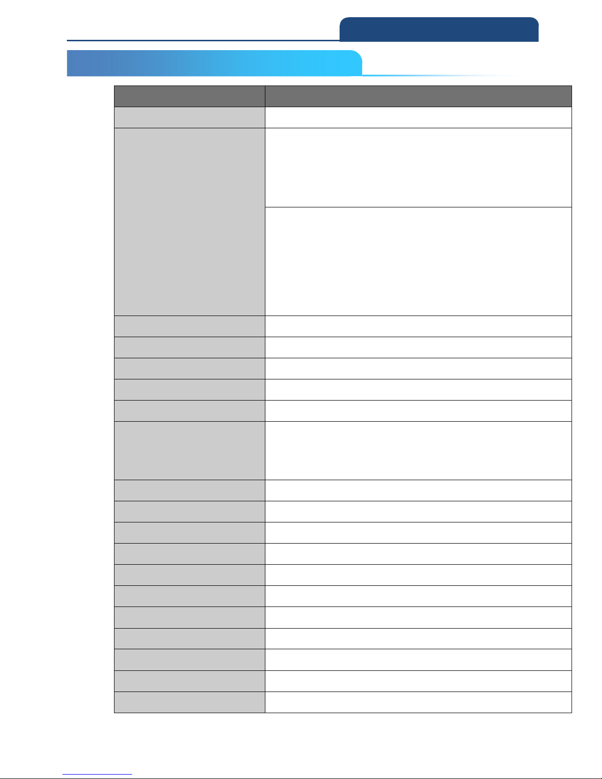
Model No. CM-2D601W
Under cabled mode interface USB COM , USB HID
Readable barcode type
1D : EAN/UPC, RSS, Code 39, Code 128, UCC/EAN 128, ISBN, ISBT, Interleaved, Matrix,
Industrial and Standard 2 of 5, Codabar, Code 93/93i, Code 11
, MSI, Plessey, Telepen,
Postal Codes, GS1 databar
2D : Codablock A, Codablock F, PDF417, MicroPDF417, Aztec Code, Data Matrix,
MaxiCode, QR Code, Chinese Sensible(Han Xin) code
Postal Codes : Australian Post, British Post, Canadian Post, China Post,Jap
anese Post,
Korea Post, Netherlands Post, Planet Code, Postnet
Optical Resolution 640 x 480 pixels
PCS Up to 0.3
Scan Rate 30 frames per second
Scan Angle Tilt : 360°, Pitch : ± 45°, Skew : ± 45°
Field of View Horizontal : 37.8°, Vertical : 28.8°
Depth of Field
Minimum Distance : 5cm / 1.97in ( Code 39, PSC 0.9, 15.6mil )
Maximum Distance : 25cm / 9.84in ( Code 39, PSC 0.9, 15.6mil )
Reading Indicator Green LED and buzzer
LED Indicator 3 color : red, green, blue
Illumination & Aiming White LED illumination; Red LED dot aimer
Configuration user manual or Windows utility ( Support Win10 )
Weight 87g
Size 135 (L) x 41 (W)x 29.9 (H)mm
Environment Humidity Up to 95% RH
Wireless connection Bluetooth Class I , outdoor 100M , support SPP, HID profile and iOS
Working Temperature
-10°C ~ 40 °C
Storage Temperature
- 40°C ~ 60 °C
Drop Durability
2-2 PRODUCT SPECIFICATION
Page 26
26
2. Introduction
Safety Standard FCC & CE Class B, VCCI
Battery Rechargeable Li-Polymer battery ( 3.7V, 1100mAH ) and charge via USB port
Ambient light Works in any lighting conditions from 0 to 100,000 lux
Power Consumption Under 400mA ( operation ) , 25mA ( standby )
Remark
We also offer CM-2D601M as 2 in 1 function without wireless
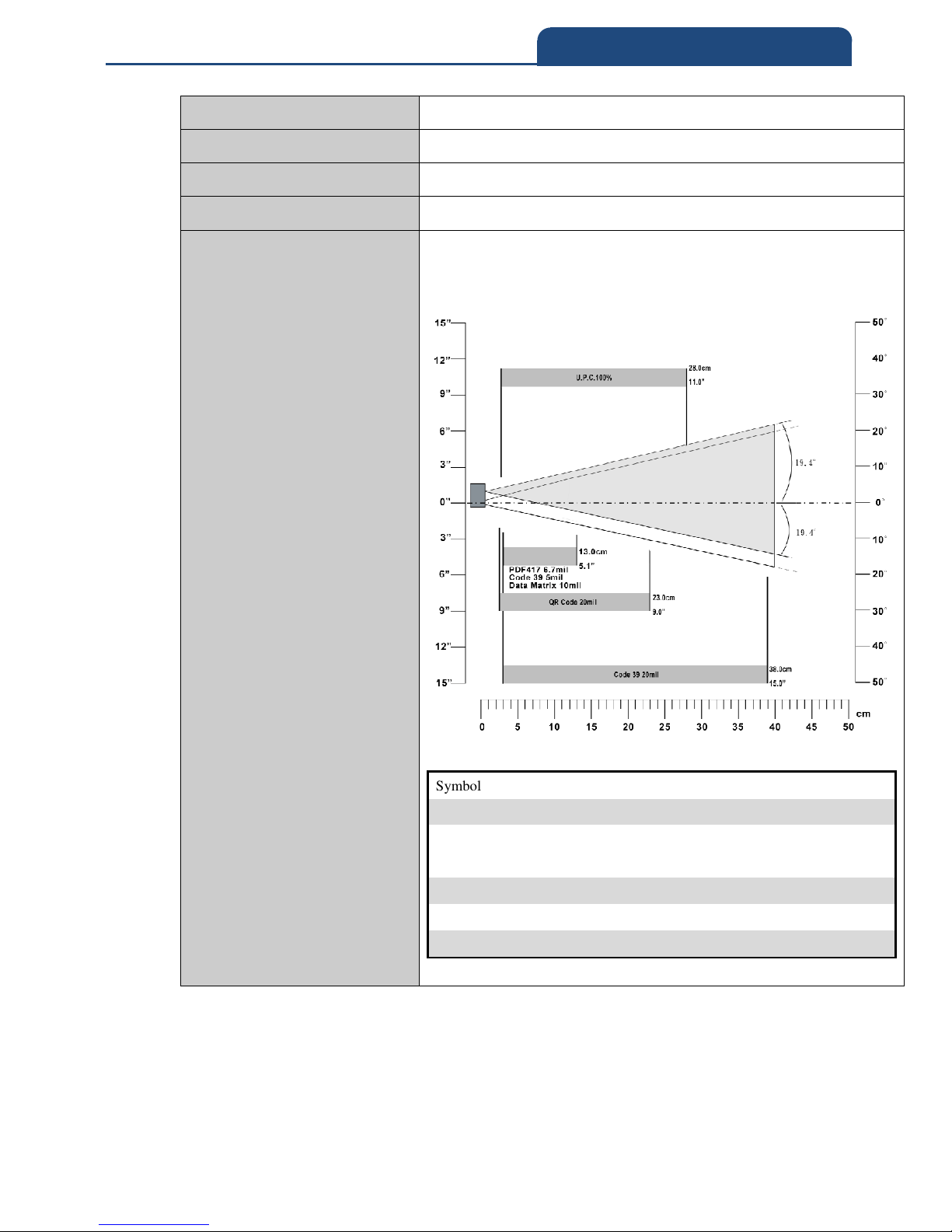
Symbology Density Minimum Distance Maximum Distance
U.P.C. 100% 5.5cm / 2.1" 28.0cm / 11.0"
Code 39 5 mil 6.1cm / 2.4" 13.0cm / 5.1"
Code 39 20 mil 6.0cm / 2.4" 38.0cm / 15.0"
PDF417 6.7 mil 6.0cm / 2.5" 12.5cm / 4.9"
Data Matrix 10 mil 6.0cm / 2.6" 13.0cm / 5.1"
QR Code 20 mil 5.0cm / 2.0" 23.0cm / 9.0"
Page 27

27
2. Introduction
2-3 PACKAGE INFORMATION
The contents of the package may vary depending on your order. While some primary devices
avail the users of their fundamental functionality, some optional items are also available for
your purchase to maximize efficiency of our product.
Inside the package contain the following items:
CM-2D601 Barcode Scanner
Quick Start
Jelly Case
Barcode Scanner Hand Strap
USB Cable
Solution CD
Browse Solution CD to locate the following how-to references for troubleshooting problems
in using CM-2D601:
Quick Start
User Manual
ISP Driver for Windows OS
Utility Program
2-3 PACKAGE INFORMATION
Page 28
28
2. Introduction
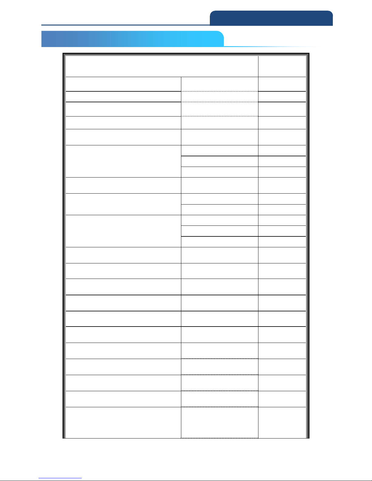
2-4 DEFAULT SYMBOLOGIES
Symbologies Default
setting
UPC-A
Enabled
UPC-E
Enabled
EAN-8
Enabled
EAN-13
Enabled
Msi
Disabled
Gs1 Databar
Omnidirectional
Enabled
Limited
Enabled
Expanded
Enabled
Gs1 Composite
Disabled
Codablock
CodablockA Disabled
CodablockF Disabled
PDF417 PDF417
Enabled
MacroPdf417
Enabled
MicroPdf417 Disabled
Tlc39
Disabled
QR Code
Enabled
DataMatrix
Enabled
MaxiCode
Disabled
Aztec Code
Enabled
ChineseSensible(HanXinCode)
Disabled
Codabar(Nw7)
Enabled
Code39
Enabled
Interleaved2of5
Enabled
Nec2of5
Enabled
Code93
Enabled
2-4 DEFAULT SYMBOLOGIES
Page 29
29
2. Introduction
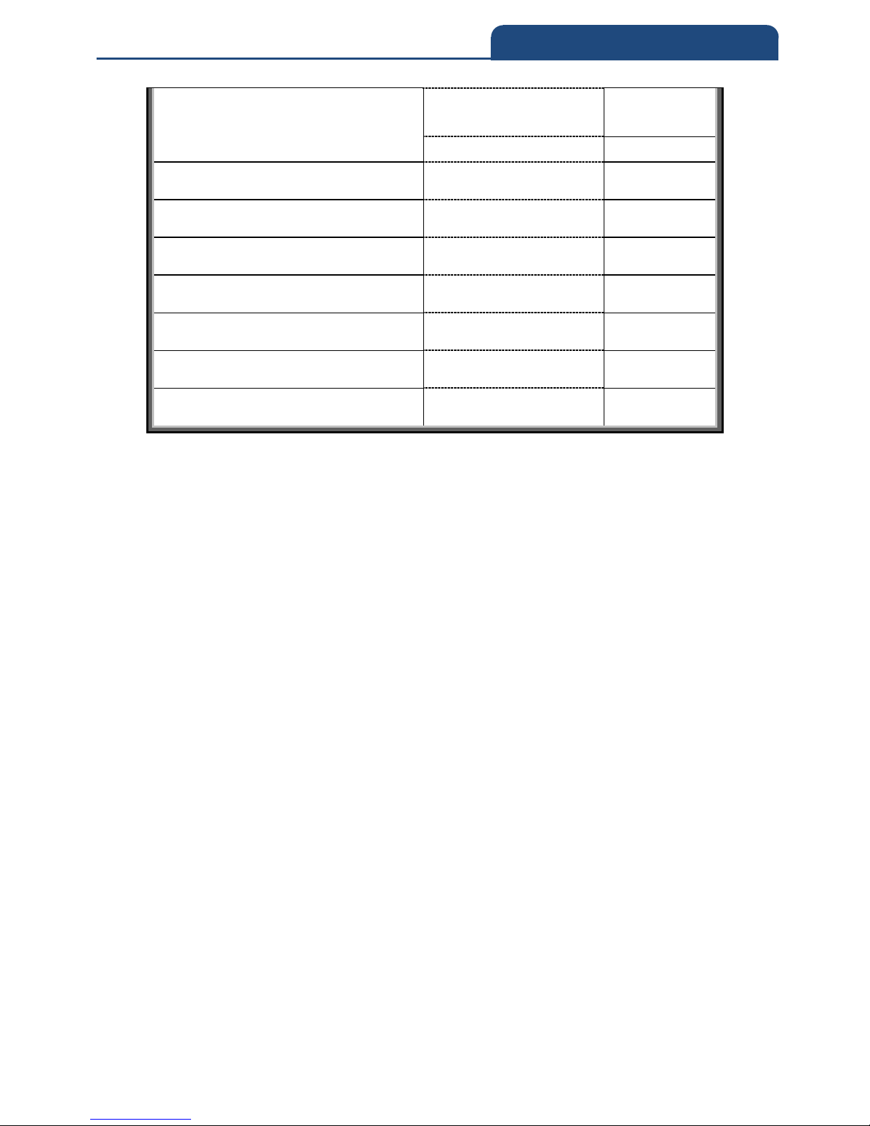
Straight2of5(Industrial2of5)
Straight2of5
(Industrial2of5)
Disabled
Straight2of5IATA Disabled
Matrix2of5
Disabled
Code11
Disabled
Code-128
Enabled
Gs1-128
Disabled
2DPostal
Disabled
ChinaPost(HongKong2of5)
Disabled
KoreaPost
Disabled
Page 30
30
2. Introduction
2-5 FUNCTION KEYS AND LED INDICATOR
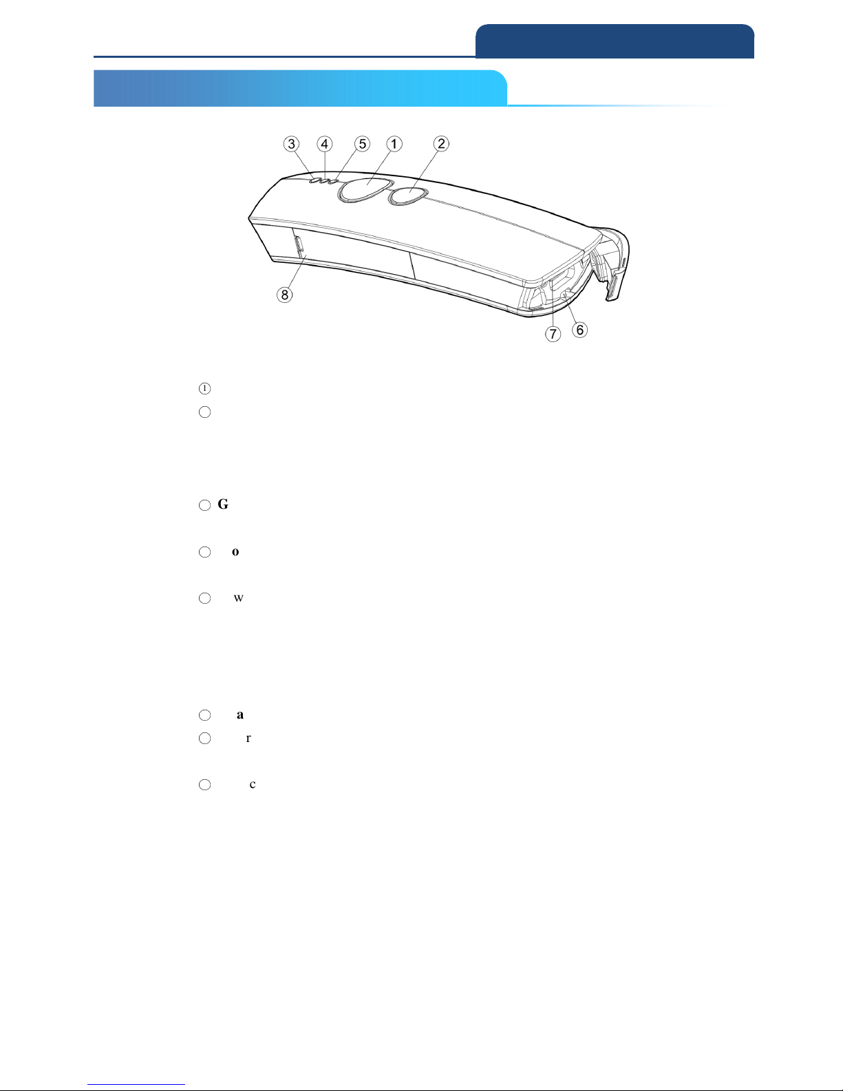
○
1
Press down Scan Button to decode or store the barcode.
○
2
Press down Small Trigger to perform versatile supplementary functions. For
instance, pressing the key will lead to erasing barcode data which have been
previously decoded in Memory Mode; it also works to pair the scanner with the
Bluetooth devices in Bluetooth Mode.
○
3
Good Read Indicator indicates whether the barcode is successfully decoded.
Green LED shows a successful decoding attempt.
○
4
Mode Indicator indicates the current operation mode. Blue LED stands for
Bluetooth mode, green LED for Cable mode, and orange LED for Memory mode.
○
5
Power Indicator indicates the charge status.
1) When plug USB cable for charging, red LED light will be on to
show a poor charge level, once the charging process is completed,
red LED will flash slowly to show a full battery charge.
2) When unplug, if the red LED flash = low battery.
○
6
Strap Hole
○
7
Secure the interface cable into USB Host in an attempt to transmit data or to
charge the battery.
○
8
Replace the battery in the Battery Compartment.
2-5 FUNCTION KEYS AND LED INDICATOR
Page 31

31
3. Scanner Configuration
Chapter 3: Scanner Configuration
3-1 CONFIGURATION BY USER MANUAL
3-2 CONFIGURATION BY SOFTWARE
Page 32
32
3. Scanner Configuration
3-1 Configuration by USER MANUAL
In the user manual, print out the related topics of setting page, simply use the
scanner to scan the barcode for configuration.
For example:
ALL Default setting: user may configure the scanner back to all default
settings, if configuration goes wrong.
ENTER
*/$%ENTR*
(Enter configuration)
Good read Beep
Disable
*7HZ0*
Level4
*7HZ4*
End
*ZEND*
(Exit Configuration)
ABORT
*ZEXT*
Abort current setting before
exit configuration
ENTER
*/$%ENTR*
(Enter configuration)
ALL DEFAULT
*ZADE*
Restore to all default setting.
3-1 CONFIGURATION BY USER MANUAL
3. Scanner Configuration
Page 33
33
3. Scanner Configuration
3-2 Configuration by SOFTWARE
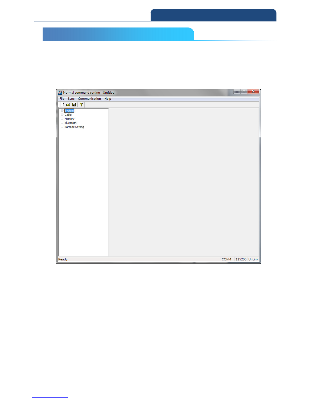
In the product CD, you can find configuration software “Normal command
setting” to configure the parameters.
Scanner general settings: (CM-2D601\Software\Normal command
setting\Scanner Setting.exe)
Note: Please refer to the related configuration chapters or additional manual
for how to use the software.
3-2 CONFIGURATION BY SOFTWARE
Page 34

34
4. Memory / Bluetooth Mode
Chapter 4: Memory / Bluetooth
Mode
4-1 Memory Mode
4-1-1 Function Switch (Bluetooth mode to Memory mode)
4-1-2 Transmitting barcode data in memory mode
4-1-3 Erase barcode data (Single data/ All data)
4-2 Bluetooth Mode
4-2-1 Function switch (Memory Mode to Bluetooth mode)
4-2-2 LED indication under Bluetooth Mode
4-2-3 Bluetooth mode selection Code Table
4-2-4 Bluetooth mode configuration by user manual
4-2-4-1 Slave Mode-Third party Bluetooth devices (Mode selection
code:1)
4-2-4-2 Master Mode -Third party Bluetooth devices (Mode
selection code: 2)
4-2-4-3 HID Mode - Third party Bluetooth devices (Mode selection
code: 3)
4-2-4-4 iOS MODE (Mode selection code : 4)
4-2-4-5 A-303 dongle MODE (Mode selection code : 5)
4-2-4-6 A-302 dongle Mode (Mode selection code:6)
4-2-5 Bluetooth parameter configuration by user manual
4-2-5-1 BT Local name
4-2-5-2 Remote Mac Address
4-2-5-3 Pin Code
Page 35

35
4. Memory / Bluetooth Mode
This chapter explains the different functions between Memory function and
Bluetooth function.
Note: If user only purchase Memory scanner model, switching to
Bluetooth mode is not applicable.
4-1 Memory Mode
4-1-1 Function switch (Bluetooth mode to Memory mode)
There are two methods of switching from Bluetooth mode to Memory mode:
1) Long keep holding Scan key, till the LED as solid color, then release Scan
key, will into the mode switching, if the LED turn to orange color, it is in
Memory mode.
OR
2) Scan the following barcode to switch from Bluetooth Mode to Memory
Mode.
(1) Enter: (Enter setting)
*/$%ENTR*
(2) To Memory mode
*ZTOM*
4-1-2 Transmitting barcode data in memory mode
There are two methods of sending the barcode data from barcode scanner.
1) Connect the USB cable between scanner and PC, keep holding Small
Trigger till the LED as solid color, then release Small Trigger to into
Transmit mode; at this moment, push Scan key will transmit the stored
data. barcode data to your word processing software,e.g. Word, excel, or
notepad.
OR
4-1-1 Function switch (Bluetooth mode to Memory mode)
4-1-2 Transmitting barcode data in memory mode
4. Memory / Bluetooth Mode
4-1 Mmory Mode
Page 36

36
4. Memory / Bluetooth Mode
2) Connect the USB cable between scanner and PC, and scan the below
barcode.
(1).Enter: (Enter setting)
*/$%ENTR*
(2).Send Data
*ZMTX*
4-1-3 Erase barcode data (single data/ all data)
Erase single data:
While holding Small Trigger and point to the scanned barcode, this action
will erase the last previous saved barcode data in the memory.
Erase all data:
1. While holding Small Trigger till Orange LED turns rapidly blinking,
2. Press down Scan Button
3. Release Scan Button and Small Trigger together, alll barcode data
saved in the memory will be erased.
OR
By scanning the below barcode:
(1).Enter: (Enter setting)
*/$%ENTR*
(2).Clear Data
*ZFCA*
Caution: Scan the “Clear Data” Barcode will erase all the barcode data
saved in the memory; make sure you have back up all the barcode data
before performing this action.
4-1-3 Erase barcode data (Single data / All data)
Page 37

37
4. Memory / Bluetooth Mode
4-2 Bluetooth Mode
User can configure different Bluetooth connection mode in different
Bluetooth environment.
1. Slave Mode (For third party Bluetooth devices)
2. Master Mode (For third party Bluetooth devices)
3. HID Mode (Third party Bluetooth devices with USB HID mode)
4. iOS Mode (iPad, iPhone)
5. A-303 Dongle Mode ( Original factory dongle, USB-HID / USB-COM
configurable)
6. A-302 Dongle Mode (Original factory dongle , USB-HID only)
4-2-1 Function switch (Memory Mode to Bluetooth mode)
There are two methods of switching from Memory mode to Bluetooth Mode:
1.Long keep holding Scan key, till the LED as solid color, then release Scan
key, it will into the mode switching,if the LED turn to blue color, it is in BT
mode.
OR
2.Scan the following barcode to Bluetooth Mode.
(1) Enter: (Enter setting)
*/$%ENTR*
(2) To Bluetooth mode
*ZTOB*
4-2 Bluetooth Mode
4-2-1 Function switch (Memory Mode to Bluetooth mode)
Page 38
38
4. Memory / Bluetooth Mode
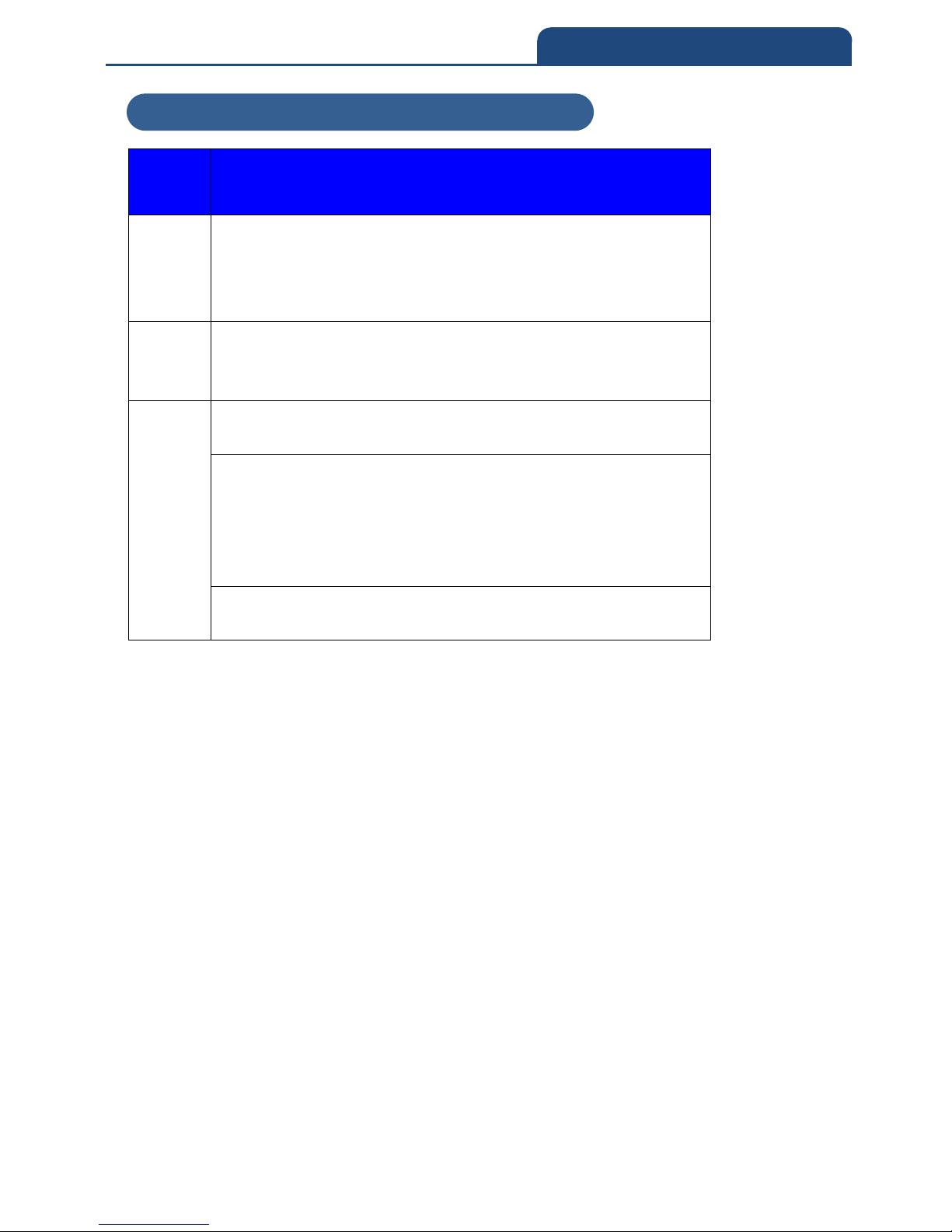
4-2-2 LED indication under Bluetooth Mode
Description
Red
Indicates the charge status. When the battery is running low,
red LED light will be on to show a poor charge level. Once the
charging process is completed, red LED will flash slowly to
show a full battery charge.
Green
Good Read Indicator indicates whether the barcode is
successfully decoded. Green LED shows a successful
decoding attempt.
Blue
Under Bluetooth mode, and Bluetooth connection is not yet
connected, the blue LED indicator will be flash per 3 seconds.
Under Bluetooth Mode and if Bluetooth connection is not
connected, press and hold pairing key(small trigger) till the
blue LED light starts flashing rapidly, press down Scan Button
at the same time and then release both buttons for Bluetooth
pairing with your device.
When power on and if Bluetooth is connected, the blue LED
will be on.
4-2-2 LED indication under Bluetooth Mode
Page 39
39
4. Memory / Bluetooth Mode
4-2-3 Bluetooth mode selection Code Table
Bluetooth mode selection code Table
Mode Description Mode selection Code
Slave Mode Applied to third party
Bluetooth dongle, or
build-in Bluetooth
devices
1
Master Mode Applied to third party
Bluetooth dongle, or
build-in Bluetooth
devices
2
HID Mode Third party Bluetooth
dongle, or build in
Bluetooth device with
USB HID mode
3
iOS Mode iPad, iPhone devices
4
A-303 Dongle Mode Applied to original
factory dongle,
USB-HID / USB-COM
configurable
5
A-302 Dongle Mode Applied to original
factory dongle,
USB-HID only
6
4-2-3 Bluetooth mode selection Code Table
Page 40

40
4. Memory / Bluetooth Mode
4-2-4 Bluetooth mode configuration by user manual
4-2-4-1 Slave Mode : Third party Bluetooth devices ( Mode selection code:
1)
This mode is for user to configure with third party Bluetooth dongle, or
build-in Bluetooth device.
For slave mode configuration; please scan below barcodes step by step.
Procedure:
(1) Enter: (Enter setting)
*/$%ENTR*
(2) Mode: (selection Spp-Slave)
*5OZ1*
(3) End (Exit setting)
*ZEND*
4-2-4-2 Master Mode - Third party Bluetooth devices (Mode selection
code: 2)
This mode is for user to configure with third party Bluetooth dongle, or
build-in Bluetooth device.
For master mode configuration, please scan below barcodes step by step.
Procedure:
(1)Enter: (Enter setting)
*/$%ENTR*
(2)Mode: (selection Spp-Master)
*5OZ2*
(3)End: (Exit setting)
*ZEND*
4-2-4 Bluetooth mode configuration by user manual
Page 41
41
4. Memory / Bluetooth Mode
4-2-4-3 HID Mode - Third party Bluetooth devices (Mode selection code:
3)
This mode is for user to configure with third party Bluetooth dongle, or
build-in Bluetooth device with USB HID.
For HID mode Configuration, please scan below barcodes step by step.
Procedure:
(1)Enter: (Enter setting)
*/$%ENTR*
(2)Mode: (selection Hid)
*5OZ3*
(3)End: (Exit setting)
*ZEND*
4-2-4-4 iOS Mode (Mode selection code : 4)
This mode is for user to configure with iPad or iPhone devices
For iOS mode configuration, please scan below barcodes step by step.
Procedure:
(1)Enter: (Enter setting)
*/$%ENTR*
(2)Mode: (selection iOS)
*5OZ4*
(3)End: (Exit setting)
*ZEND*
Page 42

42
4. Memory / Bluetooth Mode
4-2-4-5 A-303 dongle Mode (Mode selection code: 5)
This mode is for user to configure with purchased original factory dongle,
and it is USB-HID / USB-COM configurable.
For A-303 Dongle mode configuration, please scan below barcodes step by
step.
Procedure:
(1)Enter: (Enter setting)
*/$%ENTR*
(2)Mode: (selection Hid-A303)
*5OZ5*
(3)End: (Exit setting)
*ZEND*
4-2-4-6 A302 dongle Mode (Mode selection code:6)
This mode is for user to configure with purchased original factory dongle,
but it only support USB-HID.
A-302 Dongle mode, please scan below barcodes step by step.
Procedure:
(1)Enter: (Enter setting)
*/$%ENTR*
(2)Mode: (selection Hid-A302)
*5OZ6*
(3)End: (Exit setting)
*ZEND*
Page 43
43
4. Memory / Bluetooth Mode
4-2-5 Bluetooth parameter configuration by user manual
4-2-5-1 BT Local name
For Slave, Master, HID Dongle, iOS Device Mode
This option enables to assign Bluetooth the scanner name. Please refer to the
HEX ASCII table (Form 0~9, A~F). The first digit and last digit cannot be space
or “-“. If scanner name setting is incorrect, connection failure will occur.
Configuration Max. Configurable Length Default Setting
Please refer to
ASCII table
16 digits ‘SmartBt’
Procedure:
(1) Enter: (Enter setting)
*/$%ENTR*
(2) “BT Local name”
*G5S+*
(3) Scan Hexadecimal/Decimal Barcode table for input parameters.
(4) OK : (Selection confirmed)
*%OK*
(5) End: (Exit setting)
*ZEND*
Example:
Set Local name as ‘BT Scanner’
(A) Scan “Enter” barcode
(B) Scan “BT Local Name” barcode
(C) Scan parameters from Hexadecimal / Decimal barcode table =>“4”,”2”,
“5”,”4”, “2”,”0”, “5”,”3”, “6”,”3”, “6”,”1”, “6”,”E”, “6”,”E”, “6”,”5”, “7”,”2”,”OK”
(configured as ‘BT Scanner’, Please refer to ASCII TABLE)
(D) Scan “End” Barcode
4-2-5 Bluetooth parameter configuration by user manual
Page 44
44
4. Memory / Bluetooth Mode
4-2-5-2 Remote Mac Address.
1. Master Mode
Mac address configuration, total of 12 digits, Please refer to the HEX ASCII
table (From 0~9, A~F).
Configuration Max. Configurable Length Default Setting
Hexadecimal /
decimal
barcode table
12 digits 000000000000
Procedure:
(1) Enter: (Enter setting)
*/$%ENTR*
(2) “BtMacAddr”
*A4W+*
(3) Scan Hexadecimal/Decimal Barcode table for input parameters.
(4) OK : (Selection confirmed)
*%OK*
(5) End: (Exit setting)
*ZEND*
Example:
Set Remote Mac Address to 00126F006EAA
A. Scan “Enter” barcode
B. Scan “BtMacAddr” barcode
C. Scan parameters from Hexadecimal /decimal barcode table =>“0”, “0”,
“1”,”2”, “6”,”F”, “0”,”0”, “6”,”E”, “A”,”A” ”OK” (Set “Remote Mac Address
“ value to 00126F006EAA)
D. Scan “End” barcode
Note:
If scanner connection mode is ”Slave” or “HID” or “iOS” Mode, Mac Address
configuration does not required.
Page 45
45
4. Memory / Bluetooth Mode
2. A-303 , A302 Dongle Mode
Mac address configuration, total of 12 digits, Please refer to the HEX ASCII
table (From 0~9, A~F).
Configuration Max. Configurable Length Default Setting
Hexadecimal /
decimal
barcode table
12 digits 000000000000
Procedure:
(1) Enter: (Enter setting)
*/$%ENTR*
(2) “DongleBtMacAddr”
*D6O+*
(3) Scan Hexadecimal/Decimal Barcode table for input parameters.
(4) OK : (Selection confirmed)
*%OK*
(5) End: (Exit setting)
*ZEND*
Example:
Set Remote Mac Address to 001C97FF043A
A. Scan “Enter” barcode
B. Scan “DongleBtMacAddr” barcode
C. Scan parameters from Hexadecimal /decimal barcode table =>“0”, “0”,
“1”,”C”, “9”,”7”, “F”,”F”, “0”,”4”, “3”,”A” ”OK” (Set “Remote Mac Address
“ value to 001C97FF043A)
D. Scan “End” barcode
Note:
If scanner connection mode is “A-303 Dongle” or “A-302 Dongle” mode,
configuration of Mac address does required, and the configuration cannot be
“000000000000”
Page 46
46
4. Memory / Bluetooth Mode
4-2-5-3 Pin Code
When the scanner and Bluetooth device is in the pairing process, user will
need to enter the pin code for pairing confirmation. This pin code might be
generate by Bluetooth devices or preconfigured by user depends on different
mode setting.
(1) Under “Slave” or “Master” mode, pin code configuration is needed when the
pairing action is performed.
(2) Under “A-303 Dongle” or “A-302 Dongle” mode, Pin code does not
required.
(3) Under “HID” or “iOS” Mode, during pairing process, the PC or other devices
will generate the pin code, user will need to referred to that pin code, and scan
the pin code digits from Hexadecimal / Decimal table.
Configuration Range Max. Configurable Length
Default Setting
00000000 ~ 99999999 8 digits 1234
Procedure:
(1) BT Module Enter: (Enter Bluetooth setting)
*/$%ENTR*
(2) “BtPinCode”
*95C+*
(3) Scan Hexadecimal/Decimal Barcode table for input digits.
(4) OK : (Selection confirmed)
*%OK*
(5) End: (Exit setting)
*ZEND*
Example:
Set Pin Code to 5678
(A) Scan “Enter” Barcode
(B) Scan “BtPinCode” Barcode
(C) Scan parameters from Hexadecimal/Decimal table =>“5”,”6”, “7”,”8”
”OK”(Set “Pin Code “ value to 5678)
(D) Scan “End” Barcode
Page 47

47
5. Bluetooth Connection Mode Instruction
Chapter 5 : Bluetooth Connection
Mode Instruction
5-1 Slave mode Connection (For Third party Bluetooth devices)
5-2 Master mode Connection (For Third party Bluetooth Devices)
5-3 HID mode Connection (For Third party Bluetooth devices)
5-4 iOS mode Connection
5-5 A-303 Dongle Mode Connection (USB-HID / USB COM)
5-3-1 HID mode:
5-3-2 USB-COM mode
5-6 A-302 Dongle Mode Connection (USB-HID only)
Page 48
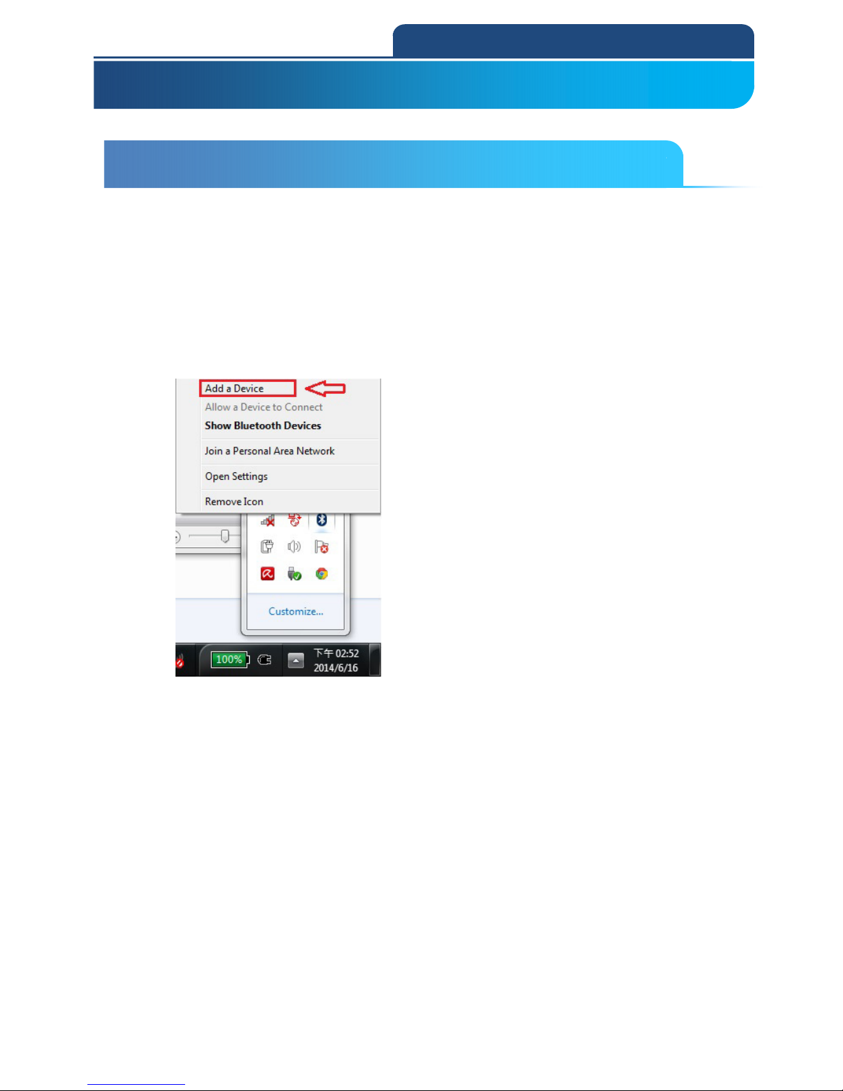
48
5. Bluetooth Connection Mode Instruction
5-1 Slave mode Connection (For Third party Bluetooth devices)
Make sure the scanner is in Bluetooth mode; please refer to chapter
4-2-1 for how to configure in Bluetooth mode.
Make sure the Mode selection code is configured as “1”. Please refer
to chapter 4-2-4-1.
1. After connect with Dongle and PC, you will see Bluetooth sign in system display.
Click right button of the mouse on this sign, and choose ”Add a Device”. See the
screen below:
After choose this function, it will start to search a nearby Bluetooth device.
5-1 Slave mode Connection (For Third party Bluetooth devices)
Page 49
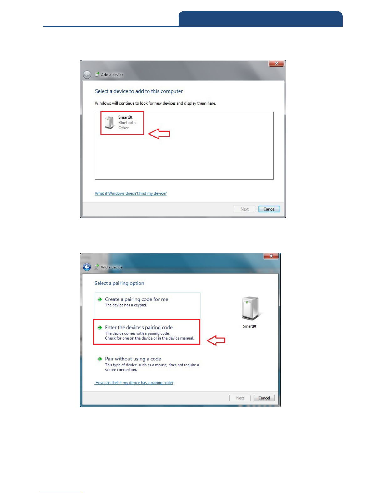
49
5. Bluetooth Connection Mode Instruction
2. Make the scanner into pairing mode, if it can search available connecting
Bluetooth device, it will show the screen below:
From all the finding devices, search the pairing Bluetooth device and click the left
button of the mouse on finding devices. The popping out screen let users set Pin code
by which way. See the screen below:
In this screen, choose ”Enter the device’s pairing code” will show up the screen
below:
Page 50
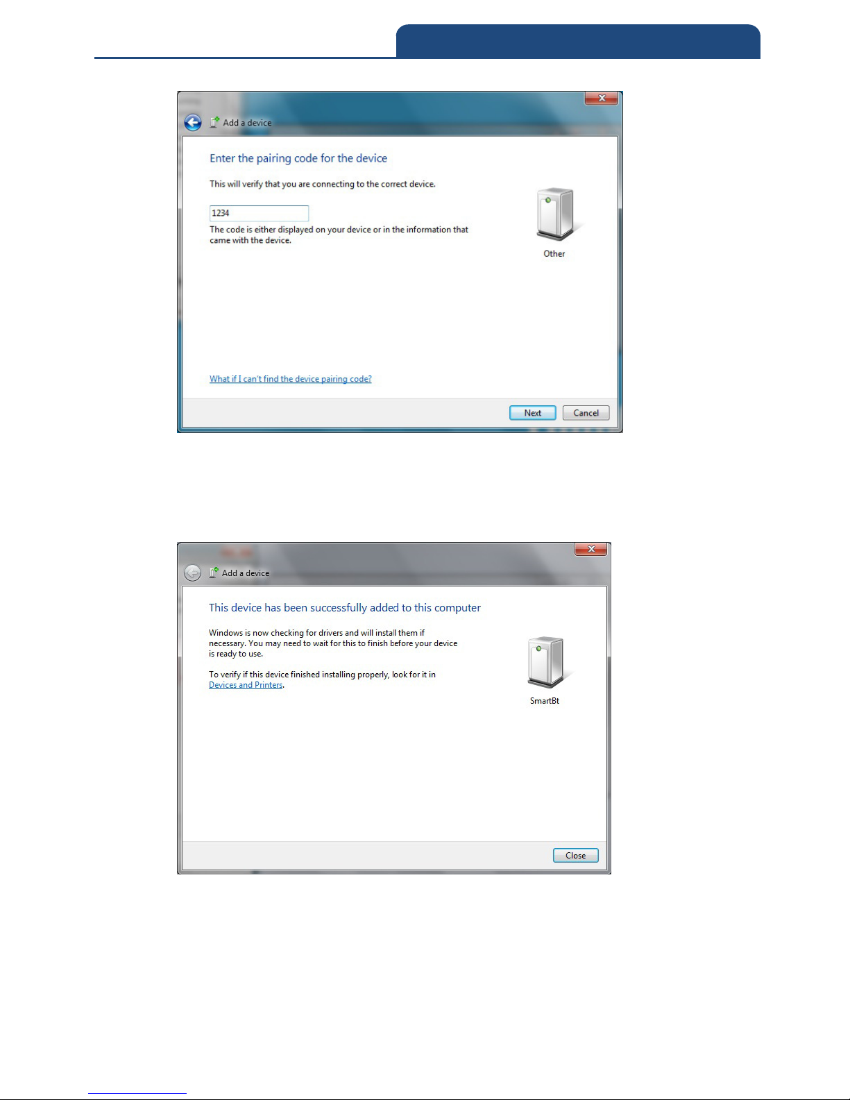
50
5. Bluetooth Connection Mode Instruction
Please key in Pin Code with 1234 in this screen. After key in Pin code,
press ”Next” then it will start to do verification of Pin code. After pass the
verification, it will go to pairing mode. After it pairs successfully, the screen will
show like down below:
Page 51
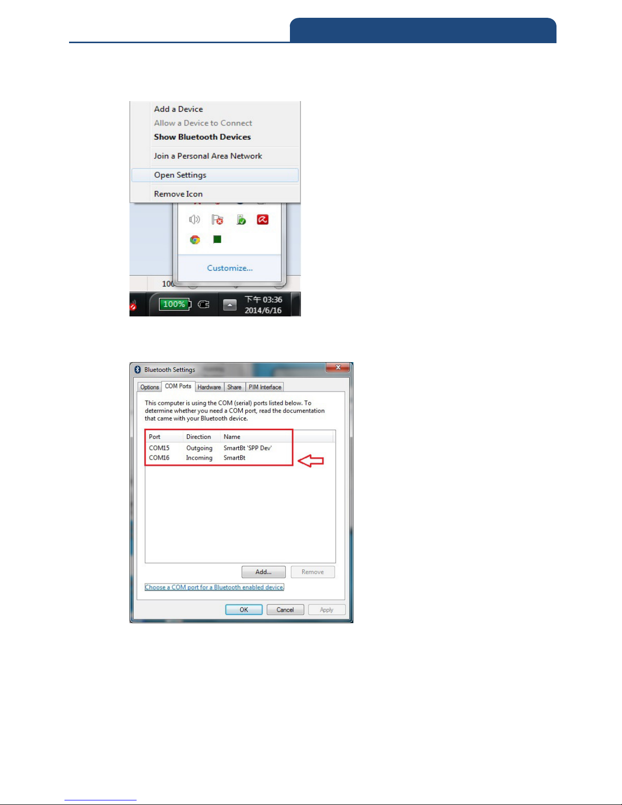
51
5. Bluetooth Connection Mode Instruction
3. After it pairs successfully, click the right button of the mouse on Bluetooth sign in
the system display. It will show screen below:
4. Choose ”Open Settings” function and switch to the page of ”COM Ports.” It will
show screen below:
From this screen can know the current using COM Port of Bluetooth device. Due
to the Bluetooth connection mode, it should choose ”COM15”(Outgoing) as using
COM Port.
Page 52
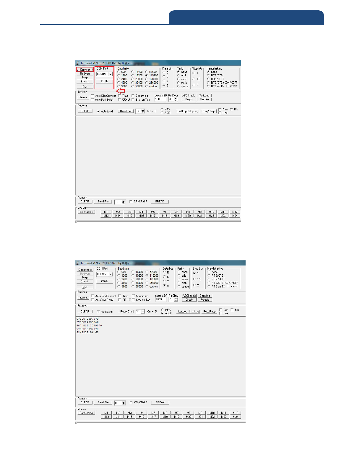
52
5. Bluetooth Connection Mode Instruction
5. Turn on terminal software, and set COM Port as ”COM15”. It will show screen
below:
After select COM port, click ”Connect” button to connect. After connect
successfully, it can start to scan barcode, and scan result will show in terminal
screen. It will show screen below:
Page 53
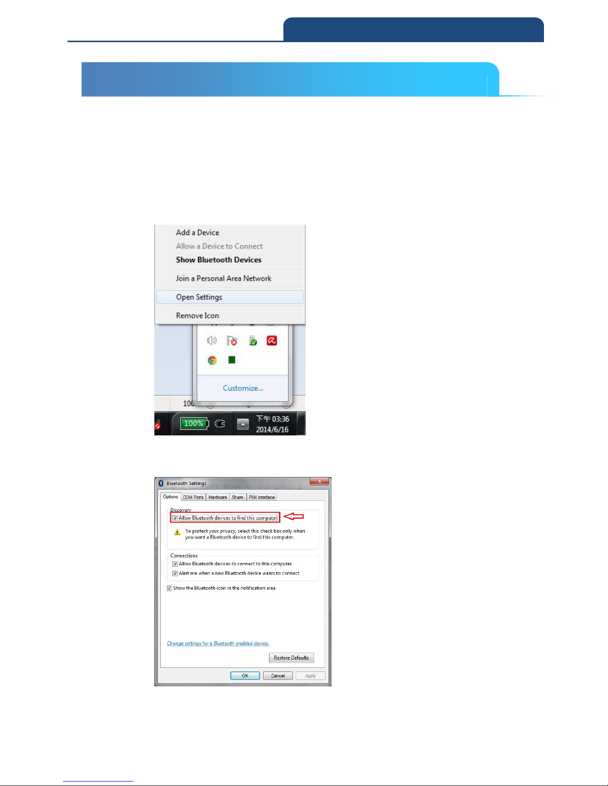
53
5. Bluetooth Connection Mode Instruction
5-2 Master mode Connection (For Third party Bluetooth Devices)
Make sure the scanner is in Bluetooth mode; please refer to chapter
4-2-1 for how to configure in Bluetooth mode.
Make sure the Mode selection code is configured as “2”. Please refer
to chapter 4-2-4-2.
1. After connect Dongle and PC, it will see Bluetooth sign in system display,
and click right button of mouse on it. It will show screen below:
Choose ”Open Settings” function, to ”Bluetooth Settings” function and
switch to ”Options” page.
In this page, click ”Allow Bluetooth devices to find this computer” to let
this Bluetooth device can be searched.
5-2 Master mode Connection (For Third party Bluetooth devices)
Page 54
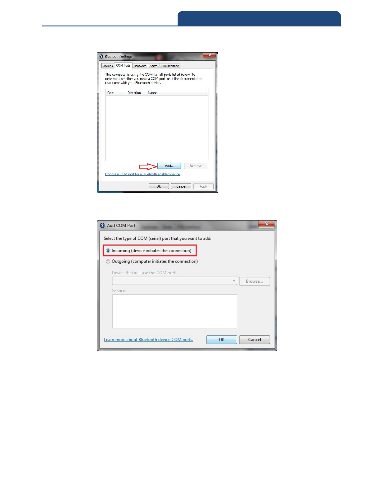
54
5. Bluetooth Connection Mode Instruction
2. Switch to ”COM ports” page. It will show screen below:
In this page, click ”Add” button to create new COM port. It will show
screen below:
In this screen, click ”Incoming(device initiates the connection)”, and
click ”OK”. In the meantime, it will create Incoming port. It will show
screen below:
Page 55
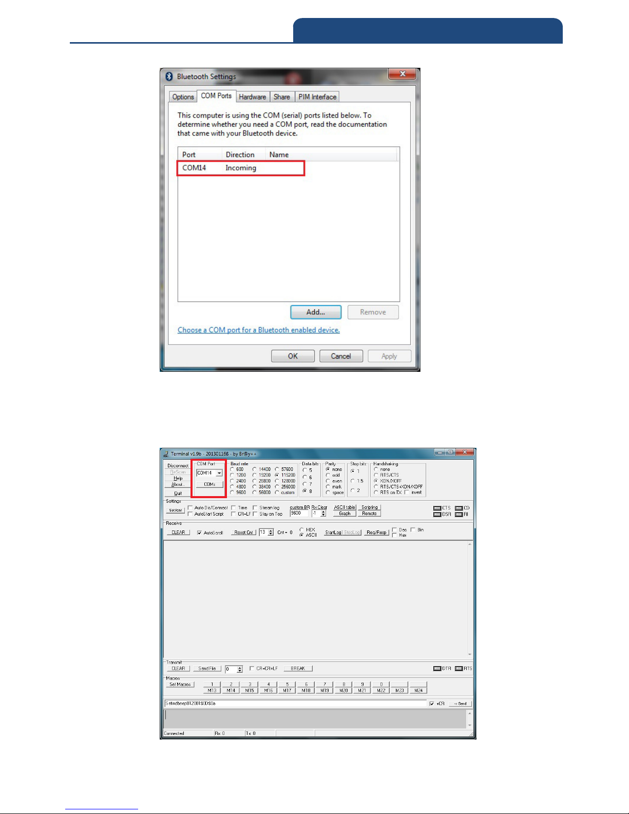
55
5. Bluetooth Connection Mode Instruction
Click ”OK” to finish setting
3. Turn on terminal software, set COM Port as Incoming port, and
click ”Connect” to start connect with this COM Port. It will show screen
below:
Page 56
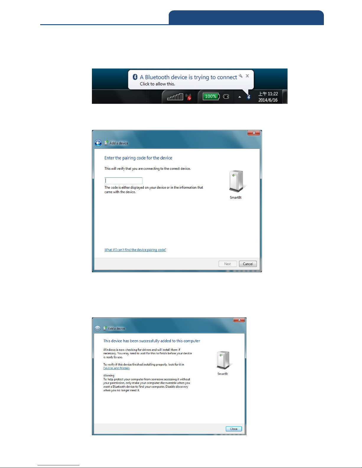
56
5. Bluetooth Connection Mode Instruction
4. Make the scanner into pairing mode. When the scanner find the PC, it will
show the information in system display to let user key Pin Code. It will
show screen below:
Click this information and it will show screen below to let user to key Pin
Code.
Please key in Pin Code with 1234 in this screen. After key in Pin code,
press ”Next” then it will start to do verification of Pin code. After pass the
verification, it will go to pairing mode. After it pairs successfully, the screen
will show like down below:
Page 57
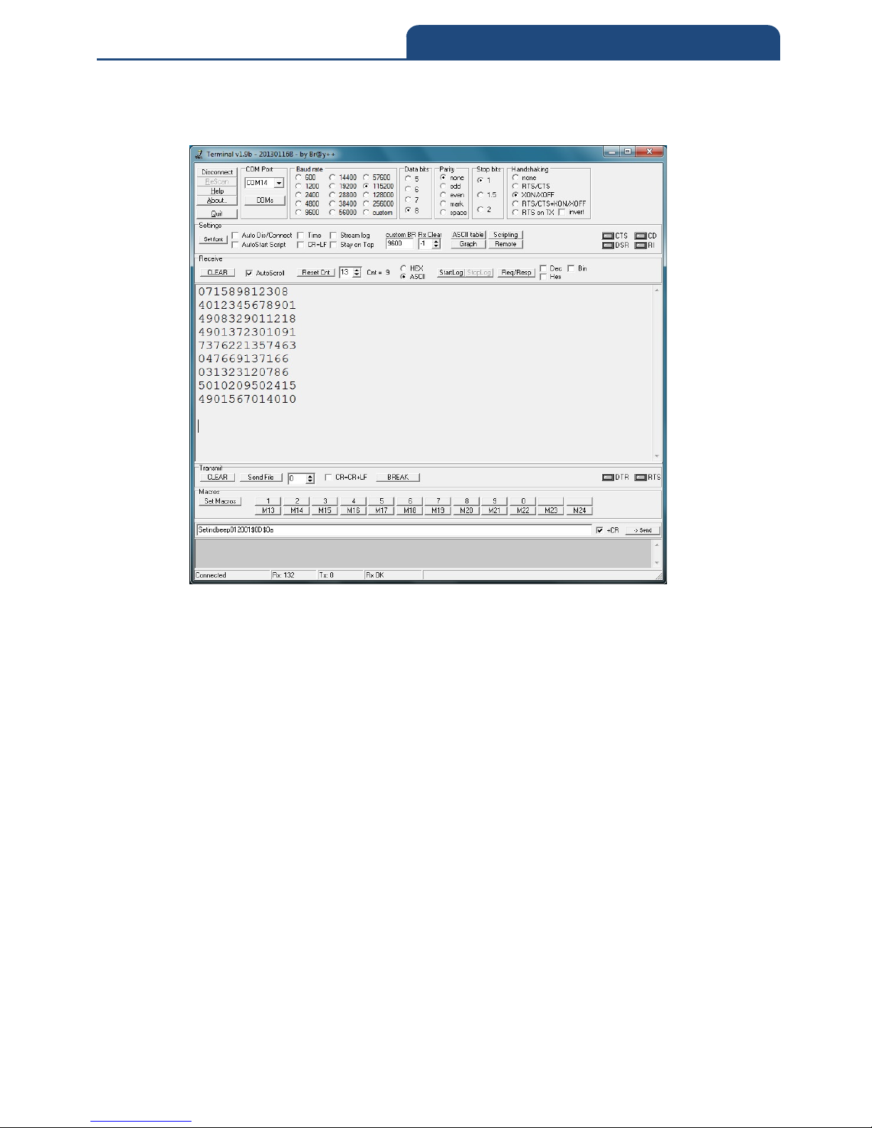
57
5. Bluetooth Connection Mode Instruction
5. In this time, it can start to scan barcode, scanned result will show up in the
terminal screen. It will show screen below:
Page 58
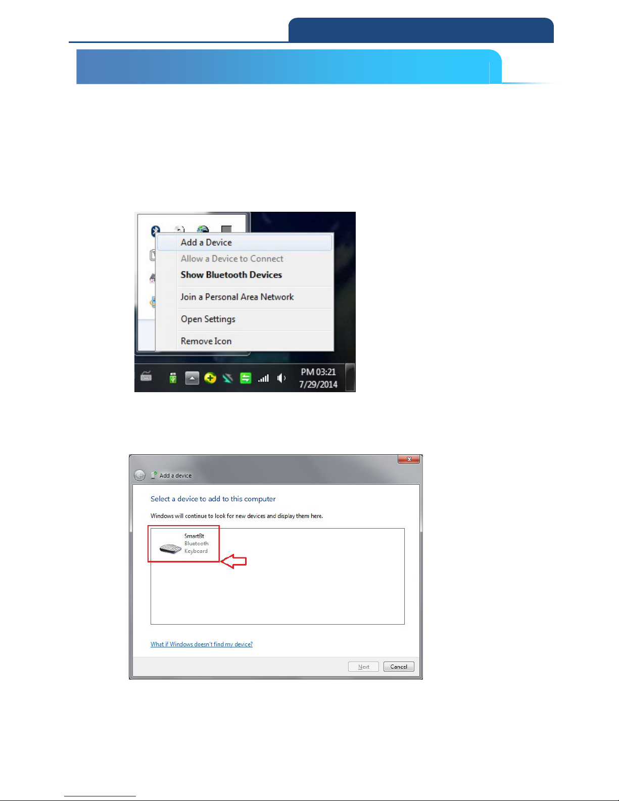
58
5. Bluetooth Connection Mode Instruction
5-3 HID mode Connection (For Third party Bluetooth devices)
Make sure the scanner is in Bluetooth mode; please refer to chapter
4-2-1 for how to configure in Bluetooth mode.
Make sure the Mode selection code is configured as “3”. Please refer
to chapter 4-2-4-3
1. After connect Dongle and PC, it will show Bluetooth sign in system display.
Click right button of the mouse. It will show screen below:
Select ”Add a Device”, it starts to search nearby available Bluetooth device. Make
the scanner into pairing mode. In the meantime, if it can find available connecting
Bluetooth device, then it will show screen below:
From all the finding Bluetooth device, search pairing device and click left button
of the mouse. From show up window, let the user to use which way to generate
Pin Code. It will show screen below:
5-3 HID mode Connection (For Third party Bluetooth devices)
Page 59
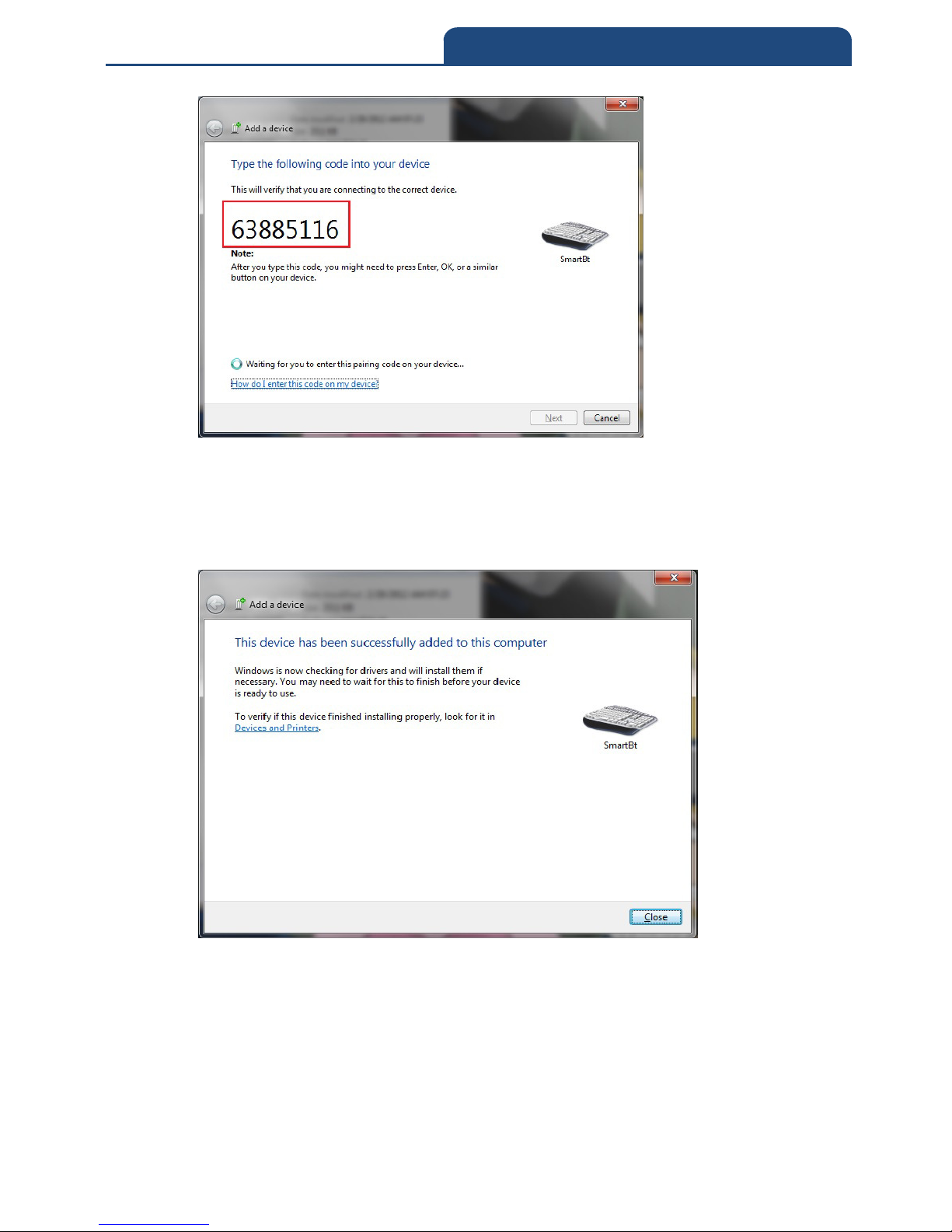
59
5. Bluetooth Connection Mode Instruction
In the meantime, user can use the scanner to scan corresponding barcode in order.
After finished scanning, scan “OK” barcode to finish Pin Code input. In this time,
it will start to verify the Pin Code. After verified the Pin Code, it will start to
connect Bluetooth connection. When it connect successfully, it will show up the
following screen:
In the meantime, turn on the software to receive scanned result and scan barcode.
It will show screen below:
Page 60
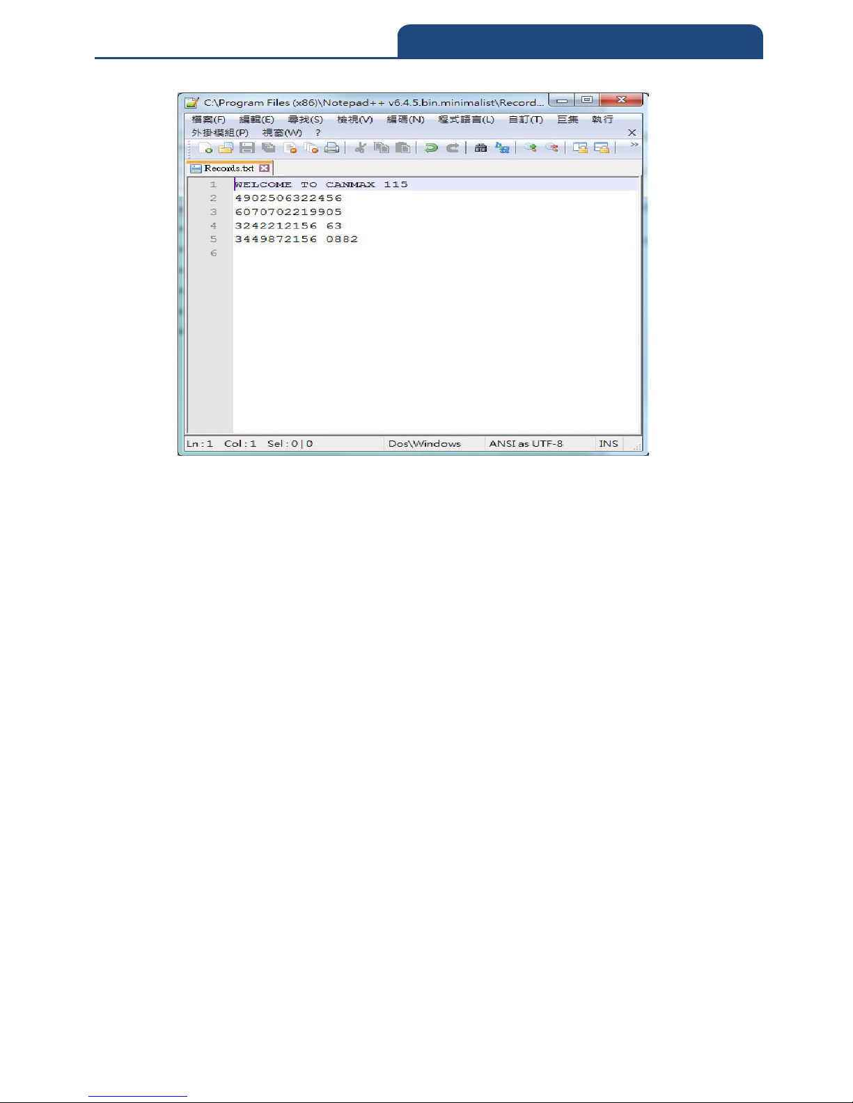
60
5. Bluetooth Connection Mode Instruction
Page 61
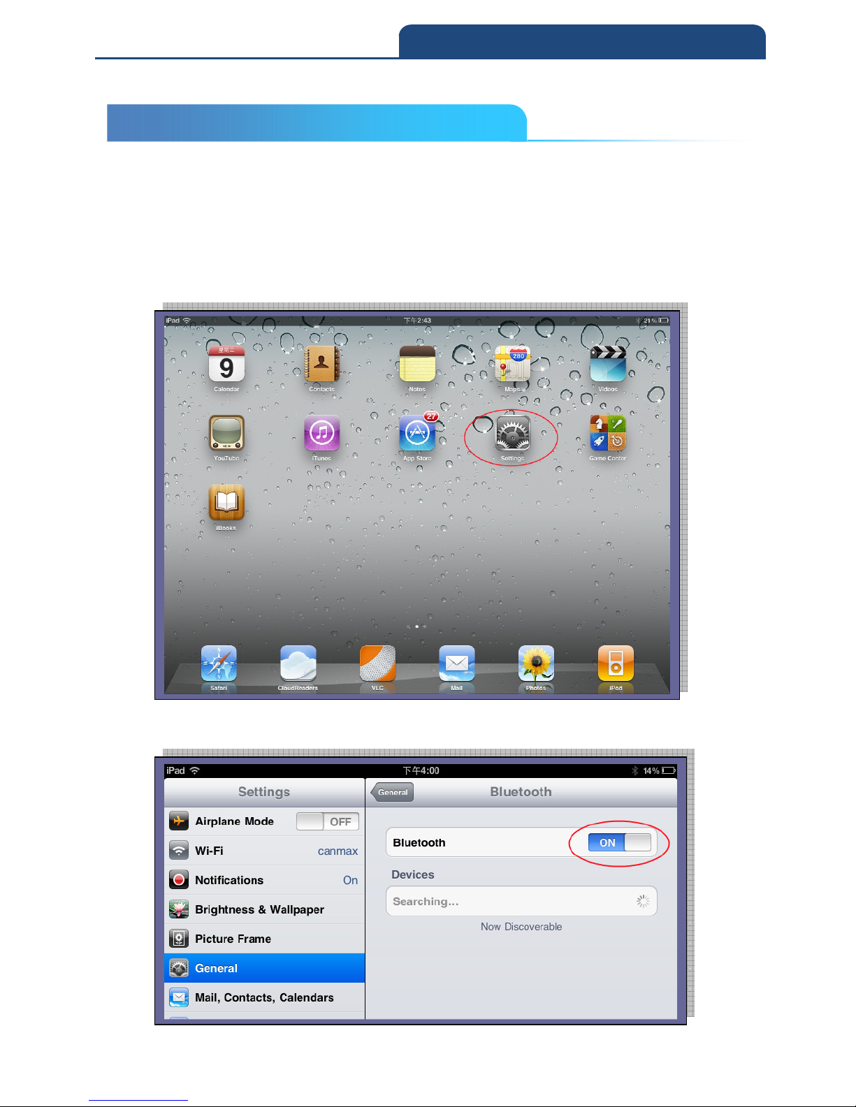
61
5. Bluetooth Connection Mode Instruction
5-4 iOS mode Connection
Make sure the scanner is in Bluetooth mode; please refer to chapter
4-2-1 for how to configure in Bluetooth mode.
Make sure the Mode selection code is configured as “4”. Please refer
to chapter 4-2-4-4
Please turn on iPad and select “settings” as below
Please access to General Bluetooth Bluetooth ON. At this stage, iPad will
start searching for Bluetooth devices
5-4 iOS mode Connection
Page 62
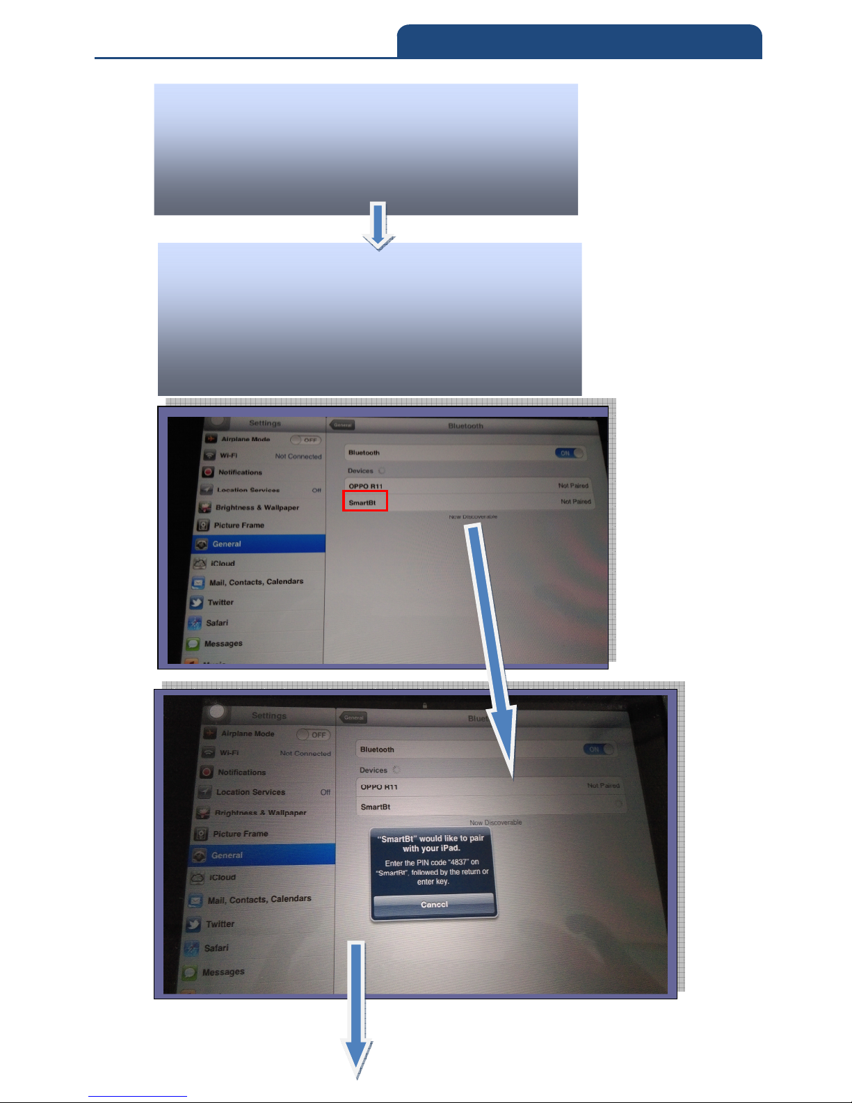
62
5. Bluetooth Connection Mode Instruction
From the scanner, press and hold pairing key(small
trigger) till the blue LED light starts flashing rapidly,
press down Scan Button at the same time and then
release both buttons for Bluetooth pairing with your
device.
From iPad, the Bluetooth will search for the Bluetooth
device (“SmartBt” as scanner name)
When iPad searched “SmartBt”, select the device for
Bluetooth pairing
Page 63
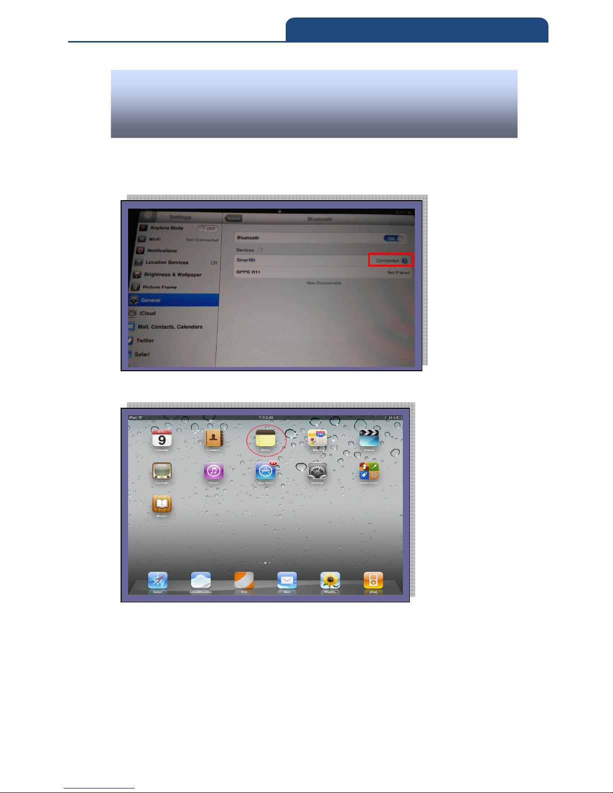
63
5. Bluetooth Connection Mode Instruction
When the pairing processes succeed, on the iPad Bluetooth devices, it will
appear as Connected. And the scanner will launch 2 beep sounds with BLUE
LED indicator ON.
Now, user can access to “Notes” from iPad application to receive barcode
data.
From the scanner, scan the digits appear on iPad to complete the pairing
process. (Note: please print out the “Hexadecimal / Decimal table(page:
377)” and scan the digits, for example: “scan 4,8,3,7 –> OK.)
Page 64
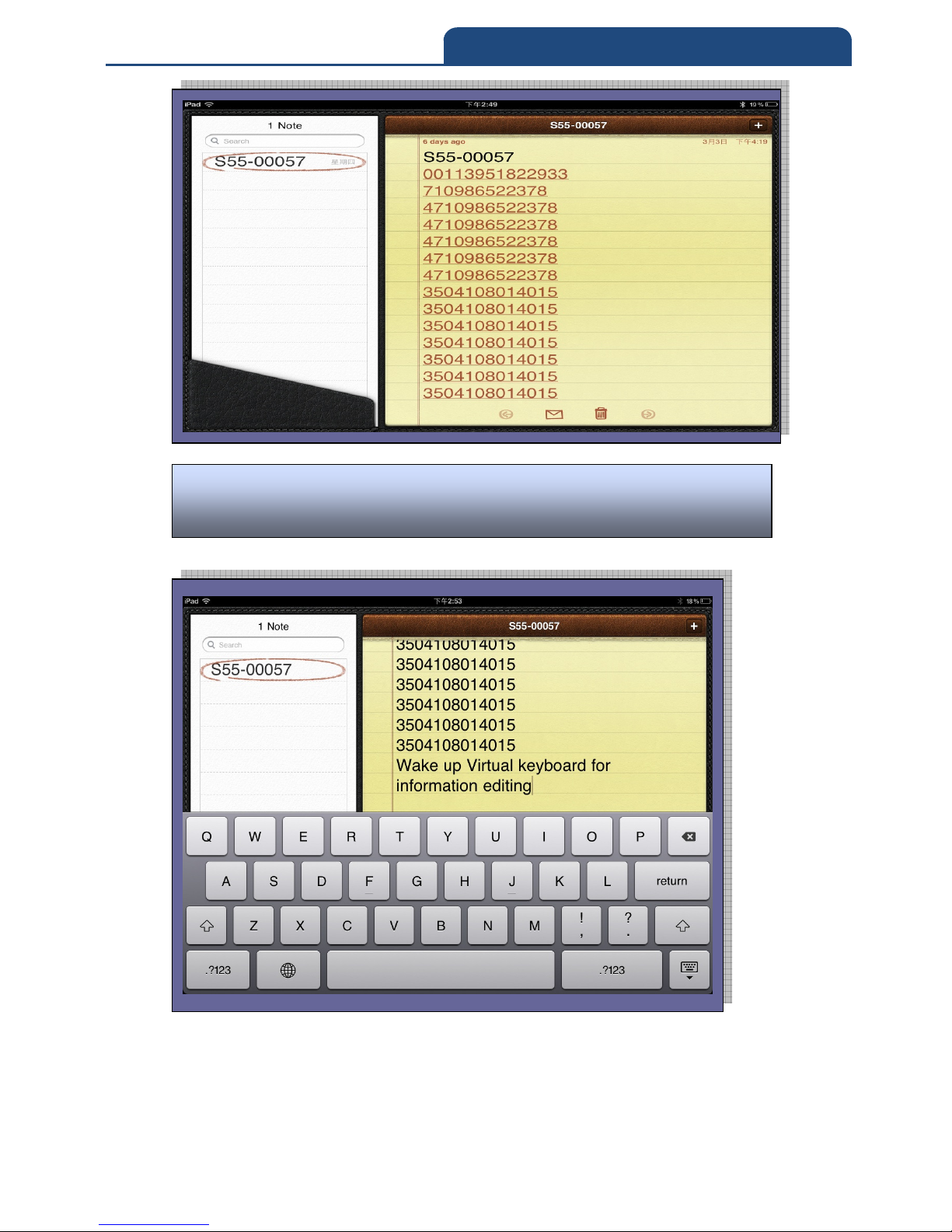
64
5. Bluetooth Connection Mode Instruction
Additional Function: press the small button from the scanner once,
iPad will wake up the virtual keyboard for information editing.
Page 65

65
5. Bluetooth Connection Mode Instruction
5-5 A-303 Dongle mode Connection(USB-HID / USB COM)
5-5-1 HID mode
Make sure the scanner is in Bluetooth mode; please refer to chapter
4-2-1 for how to configure in Bluetooth mode.
Make sure the Mode selection code is configured as “5”. Please refer
to chapter 4-2-4-5.
When Bluetooth Connection established, execute any word processing
software, for example: Word, notepad, Excel and etc. to receive to
barcode data.
When connecting scanner and Bluetooth Dongle,
Press and hold the Pairing/delete (small) key until the
blue LED blinking, then push Scan Key into pairing
mode. The scanner will establish the Bluetooth
connection. If connection successful, the Blue LED
indicator will be on. If not, please repeat the above
mention action or check the Bluetooth parameters
setting.
Insert Bluetooth SPP Dongle to PC.
5-5-1 HID mode
5-5 A-303 Dongle mode Connection(USB-HID / USB COM)
Page 66
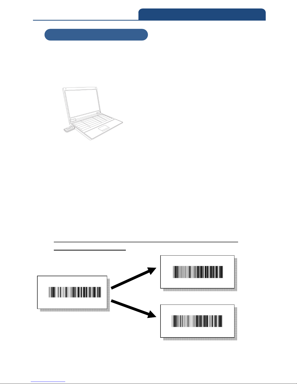
66
5. Bluetooth Connection Mode Instruction
5-5-2 USB-COM mode
Make sure the scanner is in Bluetooth mode; please refer to chapter
4-2-1 for how to configure in Bluetooth mode.
Make sure the Mode selection code is configured as “5”. Please refer
to chapter 4-2-4-5.
If the user wants to switch between USB-HID/ USB- COM mode, please
scan the following barcode.
Note: Before scan the barcode, make sure the scanner and the Bluetooth
Dongle is Connected.
When connecting scanner and Bluetooth Dongle,
Press and hold the Pairing/delete (small) key until the
blue LED blinking, then push Scan Key into pairing
mode. The scanner will establish the Bluetooth
connection. If connection successful, the Blue LED
indicator will be on. If not, please repeat the above
mention action or check the Bluetooth parameters
setting.
Insert Bluetooth SPP Dongle to PC.
ENTER
(Enter configuration)
USB
-
HID
USB
-
COM
5-5-2 USB COM mode
Page 67

67
5. Bluetooth Connection Mode Instruction
When under “USB COM” mode, please check device manager. You will know which
COM port is available, then use Terminal program to receive scan data.
Page 68

68
5. Bluetooth Connection Mode Instruction
5-6 Bluetooth HID Dongle mode Connection (USB-HID only)
Make sure the scanner is in Bluetooth mode. Please refer to chapter
4-2-1 for how to configure in Bluetooth mode.
Make sure the Mode selection code is configured as “6”. Please refer
to chapter 4-2-4-6
When Bluetooth Connection established, execute any word processing
software, for example: Word, notepad, Excel and etc. to receive to barcode
data.
When connecting scanner and Bluetooth Dongle,
Press and hold the Pairing/delete (small) key until the
blue LED blinking, then push Scan Key into pairing
mode. The scanner will establish the Bluetooth
connection. If connection successful, the Blue LED
indicator will be on. If not, please repeat the above
mention action or check the Bluetooth parameters
setting.
Insert Bluetooth HID Dongle to PC.
5-6 A302 Dongle mode Connection (USB-HID only)
Page 69

69
6. Memory / Bluetooth / Cable General Setting
Chapter 6: Memory / Bluetooth /
Cable General Setting
6-1 General Memory Mode Setting
6-1-1 Mode
6-1-2 Output Interface
6-1-3 App Type
6-1-4 Composite Triggers Functionality
6-1-5 Small Trigger Functionality
6-1-6 Dcplug Charge
6-1-7 GoodRead Beep Volume
6-1-8 Event Beep Volume
6-1-9 Warning Beep Volume
6-1-10 Tx Style
6-1-11 Tx PostProc
6-1-12 Tx Header
6-1-13 Tx Footer
6-1-14 GoodRead Vibrator
6-1-15 Event Vibrator
6-1-16 Warning Vibrator
6-1-17 Scan Time
6-1-18 Scan Idle Time
6-1-19 StandbyTime
6-1-20 Tx Preamble
6-1-21 Preamble data
6-1-22 Tx Postamble
6-1-23 Postamble data
6-1-24 Tx Prefix
6-1-25 Prefix data
6-1-26 Tx Suffix
6-1-27 Suffix data
6-1-28 Tx CodeName
6-1-29 Tx CodeId
6-1-30 CodeId Position
Page 70

70
6. Memory / Bluetooth / Cable General Setting
6-1-31 Tx Code Length
6-1-32 ForceCase
6-1-33 Tx Delimiter
6-1-34 DelimiterChar
6-1-35 Tx Control Code
6-1-36 WaitKeyTime
6-1-37 Date & Time Transmission
6-1-38 Date/Time Position
6-1-39 DateTimeSpareChar
6-1-40 Reject Same
6-2 General Bluetooth Mode Setting
6-2-1 Mode
6-2-2 Output Interface
6-2-3 App Type
6-2-4 Composite Triggers Functionality
6-2-5 Small Trigger Functionality
6-2-6 Dcplug Charge
6-2-7 GoodRead Beep Volume
6-2-8 Event Beep Volume
6-2-9 Warning Beep Volume
6-2-10 GoodRead Vibrator
6-2-11 Event Vibrator
6-2-12 Warning Vibrator
6-2-13 Pairing Time
6-2-14 Good Read Beep Freq
6-2-15 Good Read Beep Time
6-2-16 Good Read Vibrator time
6-2-17 Scan Time
6-2-18 Scan Idle Time
6-2-19 StandbyTime
6-2-20 Tx Preamble
6-2-21 Preamble data
6-2-22 Tx Postamble
6-2-23 Postamble data
6-2-24 Tx Prefix
6-2-25 Prefix data
6-2-26 Tx Suffix
6-2-27 Suffix data
6-2-28 Tx CodeName
Page 71

71
6. Memory / Bluetooth / Cable General Setting
6-2-29 Tx CodeId
6-2-30 CodeId Position
6-2-31 Tx Code Length
6-2-32 ForceCase
6-2-33 Tx Delimiter
6-2-34 DelimiterChar
6-2-35 Tx Control Code
6-2-36 Date & Time Transmission
6-2-37 Date/Time Position
6-2-38 DateTimeSpareChar
6-3 General Cable Mode Setting
6-3-1 Mode
6-3-2 Output Interface
6-3-3 App Type
6-3-4 Composite Triggers Functionality
6-3-5 Small Trigger Functionality
6-3-6 Dcplug Charge
6-3-7 GoodRead Beep Volume
6-3-8 Event Beep Volume
6-3-9 Warning Beep Volume
6-3-10 GoodRead Vibrator
6-3-11 Event Vibrator
6-3-12 Warning Vibrator
6-3-13 Power on light
6-3-14 Good Read Beep Freq
6-3-15 Good Read Beep Time
6-3-16 Good Read Vibrator time
6-3-17 Scan Time
6-3-18 Tx Preamble
6-3-19 Preamble data
6-3-20 Tx Postamble
6-3-21 Postamble data
6-3-22 Tx Prefix
6-3-23 Prefix data
6-3-24 Tx Suffix
6-3-25 Suffix data
6-3-26 Tx CodeName
6-3-27 Tx CodeId
6-3-28 CodeId Position
Page 72

72
6. Memory / Bluetooth / Cable General Setting
6-3-29 Tx Code Length
6-3-30 ForceCase
6-3-31 Tx Delimiter
6-3-32 DelimiterChar
6-3-33 Tx Control Code
6-3-34 Date & Time Transmission
6-3-35 Date/Time Position
6-3-36 DateTimeSpareChar
6-4 Scanner Configuration by Software
6-4-1 Firmware update
6-4-2 Scanner Configuration
Page 73

Enter 73 End
*/$%ENTR* *ZEND*
6. Memory / Bluetooth / Cable General Setting
6-1 General Memory Mode Setting
6-1-1 Mode
This function to set operation Mode:
(1) Good Read Off: When pressing “Scan” key, turning on scanning light,
scanning barcode correctly or over loading time to make barcode scanning
incorrectly, the light will be turned off.
(2) Momentary: When pressing “Scan” key, turning on scanning light,
scanning barcode correctly or release “Scan” key, the light will be turned
off.
(3) Toggle: Scan Toggle label if you intend to gain more flexibility in when to
read a barcode. A press on Scan Button will lead in switching on the light
whereas either a successful decoding of a barcode or giving it Scan
button press correspondingly switches off the light.
Please scan the appropriate label to determine your preferred scan mode.
*6LC0*
Good Read Off
*6LC1*
Momentary
*6LC3*
Toggle
6. Memory / Bluetooth/ Cable General
6-1 General Memory Mode Setting
6-1-1 Mode
Page 74
Enter 74 End
*/$%ENTR* *ZEND*
6. Memory / Bluetooth / Cable General Setting
6-1-2 Output Interface
Please scan the appropriate barcode to specify the output interface
*0LF0*
Cable
*0LF1*
Usb-Keyboard
*0LF2*
Usb-Spp
*0LF5*
Usb-Mass
6-1-3 App Type
Whether to enable special setting
Normal
NormalNormal
Normal: Do not enable
MobilePhone
MobilePhoneMobilePhone
MobilePhone: When scanning the barcode on the phone, to set up this function for
better and accurate scanning
*7LD0*
Normal
*7LD1*
MobilePhone
6-1-2 Output Interface
6-1-3 App Type
Page 75
Enter 75 End
*/$%ENTR* *ZEND*
6. Memory / Bluetooth / Cable General Setting
6-1-4 Composite Triggers Functionality
ctionality
Some supplementary functions are necessarily executed by using composite
triggers though Scan Button primarily serves to scan barcodes, and Small
Trigger to initiate data transmission. In Memory mode, all the scanned barcode
data will be deleted by pressing small trigger and Scan button in a specified
sequence described below: while holding the small key till the orange LED light
starts flashing rapidly, press down Scan key at the same time and then release
both buttons. Scan the appropriate label to DelAll or disable functionality of file
deletion.
*1LG0*
Disable
*1LG1*
DelAll
6-1-5 Small Trigger Functionality
Small Trigger is designed to perform various supplementary operations, from
deleting single scanned , data charge to switching to data transmission mode,
according to the length of time the button has been pressed. To facilitate the
associated operations with Small Trigger, this parameter is available to specify
the degree of Small Trigger’s functionality. On the other hand, when Mem Tx is
enabled, the device able to switch to data transmission mode. By default,
Small Trigger is set for maximum functionality without limit.
*2LH1*
Del
*2LH2*
MemTx
*2LH3*
Normal
6-1-4 Composite Triggers Functionality
6-1-5 Small Trigger Functionality
Page 76
Enter 76 End
*/$%ENTR* *ZEND*
6. Memory / Bluetooth / Cable General Setting
6-1-6 Dcplug Charge
Scan the appropriate barcode to determine whether to initiate battery charge
whenever the device is well connected to host PC using an interface cable.
*3LI0*
Disable
*3LI1*
Enable
6-1-7 GoodRead Beep Volume
Scan the appropriate barcode to specify the volume of Good Read Buzzer
when a barcode is decoded successfully. The higher level indicates the louder
sound
.
*4LJ0*
Disable
*4LJ1*
Level1
*4LJ2*
Level2
*4LJ3*
Level3
*4LJ4*
Level4
6-1-6 Dcplug Charge
6-1-7 GoodRead Beep Volume
Page 77
Enter 77 End
*/$%ENTR* *ZEND*
6. Memory / Bluetooth / Cable General Setting
6-1-8 Event Beep Volume
Scan the appropriate barcode to specify the volume of Normal Event Buzzer
when certain operations, such as switching operation modes, entering data
transmission mode, and deleting all saved barcodes, are initiated by using
Scan Key or Small Key. The higher level indicates the louder sound.
*6LL0*
Disable
*6LL1*
Level1
*6LL2*
Level2
*6LL3*
Level3
*6LL4*
Level4
6-1-9 Warning Beep Volume
Scan the appropriate barcode to specify the volume of Warning Buzzer when
an error occurs. The higher level indicates the louder sound.
*8LN0*
Disable
*8LN1*
Level1
*8LN2*
Level2
*8LN3*
Level3
*8LN4*
Level4
6-1-8 Event Beep Volume
6-1-9 Warning Beep Volume
Page 78
Enter 78 End
*/$%ENTR* *ZEND*
6. Memory / Bluetooth / Cable General Setting
6-1-10 Tx Style
Scan the appropriate barcode to specify data transmission unit which will
determine how the scanned barcodes will be sent out from the barcode
reader in data transit. By default, barcode data will be transmitted in batches;
alternatively, scan 1By1 label to transmit single barcode data at a time by
giving Scan Button a press.
*4LS0*
Normal
*4LS1*
1By1
6-1-11 Tx PostProc
Scan the appropriate barcode to determine whether to delete saved barcode
data in memory after data transmission is completed
*5LT0*
Disable
*5LT1*
Enable
6-1-10 Tx Style
6-1-11 Tx PostProc
Page 79
Enter 79 End
*/$%ENTR* *ZEND*
6. Memory / Bluetooth / Cable General Setting
6-1-12 Tx Header
Scan the appropriate barcode to determine whether or not to transmit header
information as part of transmitted data in Memory mode.
*6LU0*
Disable
*6LU1*
Enable
6-1-13 Tx Footer
Scan the appropriate barcode to determine whether or not to transmit footer
information as part of transmitted data in Memory mode.
*7LV0*
Disable
*7LV1*
Enable
6-1-14 GoodRead Vibrator
Scan the appropriate barcode to enable or disable Good Read Vibrator when a
barcode is successfully decoded.
*5LK0*
Disable
*5LK1*
Enable
6-1-14 GoodRead Vibrator
6-1-13 Tx Footer
6-1-12 Tx Header
Page 80
Enter 80 End
*/$%ENTR* *ZEND*
6. Memory / Bluetooth / Cable General Setting
6-1-15 Event Vibrator
Mode Event Vibrator is used to give a vibration signal whenever certain
operations, such as switching operation modes, entering data transmission
mode, and deleting all saved barcodes, are initiated by using Scan Button or
Small Trigger. Scan the appropriate barcode to enable or disable Mode Event
Vibrator.
*7LM0*
Disable
*7LM1*
Enable
6-1-16 Warning Vibrator
Scan the appropriate barcode to enable or disable Warning Vibrator when an
error occurs
.
*0LO0*
Disable
*0LO1*
Enable
6-1-15 Event Vibrator
6-1-16 Warning Vibrator
Page 81
Enter 81 End
*/$%ENTR* *ZEND*
6. Memory / Bluetooth / Cable General Setting
6-1-17 Scan Time
Definition :
1. The duration from user’s action to the next operation step of barcode
scanner. ( E.g. Default setting : 10 Secs. To switch the operation mode,
hold “Scan” key for 10 seconds, and LED light will start blinking. )
2. The time required to shut down scanning light when no barcode is
scanned.
*6N1+*
Configuration Range Unit Default Setting
1 ~ 30 Secs 1 Sec 10 Secs
Procedure
(A) Scan “Enter” barcode
(B) Scan “Scan Time” barcode
(C) Scan parameters from Hexadecimal / Decimal table
(D) Scan “OK“ barcode
(E) Scan “End” barcode
6-1-17 Scan Time
Page 82
Enter 82 End
*/$%ENTR* *ZEND*
6. Memory / Bluetooth / Cable General Setting
6-1-18 Scan Idle Time
The device will switch to power-saving mode after remaining idle for a while.
This parameter is thus used to specify the length of time allocated for the
scanner to elapse before power-saving mode is initiated.
*7N2+*
Configuration Range Unit Default Setting
1 ~ 255 Secs 1 Sec 15 Secs
Procedure
(A) Scan “Enter” barcode
(B) Scan “Scan Idle Time” barcode
(C) Scan parameters from Hexadecimal / Decimal table
(D) Scan “OK“ barcode
(E) Scan “End” barcode
6-1-18 Scan Idle Time
Page 83
Enter 83 End
*/$%ENTR* *ZEND*
6. Memory / Bluetooth / Cable General Setting
6-1-19 StandbyTime
After lengthy idleness, the device will first be put into standby state in which the
machine is still able to react to the emergent request yet running in lower
power consumption. This parameter refers to the amount of time allocated for
the device to stay in standby before being totally shut down..
*8N3+*
Configuration Range Unit Default Setting
0 ~ 2550 Secs 10 Sec 30 Secs
6-1-20 Tx Preamble
Preamble Code refers to a sequence of characters which precedes both Prefix
Code and barcode data during data transmission. Scan the appropriate
barcode to enable or disable Preamble Code.
*5W00*
Disable
*5W01*
Enable
Procedure
(A) Scan “Enter” barcode
(B) Scan “StandbyTime” barcode
(C) Scan parameters from Hexadecimal / Decimal table
(D) Scan “OK“ barcode
(E) Scan “End” barcode
6-1-19 StandbyTime
6-1-20 Tx Preamble
Page 84
Enter 84 End
*/$%ENTR* *ZEND*
6. Memory / Bluetooth / Cable General Setting
6-1-21 Preamble data
Setting Preamble code content
*1WW+*
6-1-22 Tx Postamble
Postamble Code refers to a sequence of characters which appends to both
barcode data and Suffix Code during data transmission. Scan the appropriate
barcode to enable or disable Postamble Code.
*6W10*
Disable
*6W11*
Enable
Configuration Length
Default Setting
8 NULL
Procedure
(A) Scan “Enter” barcode
(B) Scan “Preamble data” barcode
(C) Scan parameters from Hexadecimal / Decimal table
(D) Scan “OK“ barcode
(E) Scan “End” barcode
6-1-22 Tx Postamble
6-1-21 Preamble data
Page 85
Enter 85 End
*/$%ENTR* *ZEND*
6. Memory / Bluetooth / Cable General Setting
6-1-23 Postamble data
Setting Postamblecode content
*1X4+*
6-1-24 Tx Prefix
Prefix Code is a sequence of characters interposed between Preamble Code
and barcode data during data transmission. Scan the appropriate barcode to
enable or disable Prefix Code.
*7W20*
Disable
*7W21*
Enable
Configuration Length
Default Setting
8 <CR><LF>(0x0D0x0A)
Procedure
(A) Scan “Enter” barcode
(B) Scan “Postamble data” barcode
(C) Scan parameters from Hexadecimal / Decimal table
(D) Scan “OK“ barcode
(E) Scan “End” barcode
6-1-23 Postamble data
6-1-24 Tx Prefix
Page 86
Enter 86 End
*/$%ENTR* *ZEND*
6. Memory / Bluetooth / Cable General Setting
6-1-25 Prefix data
Setting Prefix content
*0XC+*
6-1-26 Tx Suffix
Suffix Code is a sequence of characters interposed between barcode data and
Postamble Code during data transmission. Scan the appropriate barcode to
enable or disable Suffix Code.
*8W30*
Disable
*8W31*
Enable
Configuration Length
Default Setting
8 NULL
Procedure
(A) Scan “Enter” barcode
(B) Scan “Prefix data” barcode
(C) Scan parameters from Hexadecimal / Decimal table
(D) Scan “OK“ barcode
(E) Scan “End” barcode
6-1-25 Prefix data
6-1-26 Tx Suffix
Page 87
Enter 87 End
*/$%ENTR* *ZEND*
6. Memory / Bluetooth / Cable General Setting
6-1-27 Suffix data
Setting Suffix content
*8XK+*
6-1-28 Tx CodeName
This configuration enables to show the barcode symbology name. Symbology
name will be showing in front of barcode data..
*0W40*
Disable
*0W41*
Enable
Configuration Length
Default Setting
8 NULL
Procedure
(A) Scan “Enter” barcode
(B) Scan “Suffix data” barcode
(C) Scan parameters from Hexadecimal / Decimal table
(D) Scan “OK“ barcode
(E) Scan “End” barcode
6-1-27 Suffix data
6-1-28 Tx CodeName
Page 88
Enter 88 End
*/$%ENTR* *ZEND*
6. Memory / Bluetooth / Cable General Setting
6-1-29 Tx CodeId
When scanning the barcode, User might want to know the symbology of the
barcode ID, This configuration enables to display the Code ID.
*1W50*
Disable
*1W51*
Enable
6-1-30 CodeId Position
When “Tx CodeID” is “Enable”, user can configure the output position of Code
ID (Before Barcode/ After Barcode).
*2W60*
Before
*2W61*
After
6-1-31 Tx Code Length
If user needs to know the length of the barcode data, this configuration enables
to indicate the barcode length in front of barcode data.
*4W80*
Disable
*4W81*
Enable
6-1-30 CodeId Position
6-1-29 Tx CodeId
6-1-31 Tx Code Length
Page 89
Enter 89 End
*/$%ENTR* *ZEND*
6. Memory / Bluetooth / Cable General Setting
6-1-32 ForceCase
This configuration enables to convert all output digits to be same printing-case;
even one barcode may have two kinds of case.
*3WG0*
None
*3WG1*
Inverse
*3WG2*
Lower
*3WG3*
Upper
6-1-33 Tx Delimiter
Scan the appropriate barcode to determine whether or not to interpose the
delimiter parameter between the decoded message and timestamps..
*8WC0*
Disable
*8WC1*
Enable
6-1-32 ForceCase
6-1-33 Tx Delimiter
Page 90
Enter 90 End
*/$%ENTR* *ZEND*
6. Memory / Bluetooth / Cable General Setting
6-1-34 DelimiterChar
Setting Delimiter content
*2WO+*
6-1-35 Tx Control Code
Scan the appropriate barcode to determine whether or not to transmit control
code info along with the decoded message if the scanned barcode contains
the special ASCII code.
*0WD0*
Disable
*0WD1*
Enable
Configuration Length
Default Setting
1 “ “
Procedure
(A) Scan “Enter” barcode
(B) Scan “DelimiterChar” barcode
(C) Scan parameters from Hexadecimal / Decimal table
(D) Scan “OK“ barcode
(E) Scan “End” barcode
6-1-34 DelimiterChar
6-1-35 Tx Control Code
Page 91
Enter 91 End
*/$%ENTR* *ZEND*
6. Memory / Bluetooth / Cable General Setting
6-1-36 WaitKeyTime
When “Tx Style” is set as “1By1”, to define the time that barcode scanner
stands by until “Scan” key is pressed.
*4WQ+*
Configuration Range Unit Default Setting
0 ~ 255 Secs 1 Sec 30 Secs
6-1-37 Date & Time Transmission
Whether or not to transmit Date or Time information
Date
Time
*5W90*
Disable
*6WA0*
Disable
*5W91*
Enable
*6WA1*
Enable
Procedure
(A) Scan “Enter” barcode
(B) Scan “WaitKeyTime” barcode
(C) Scan parameters from Hexadecimal / Decimal table
(D) Scan “OK“ barcode
(E) Scan “End” barcode
6-1-36 WaitKeyTime
6-1-37 Date & Time Transmission
Page 92
Enter 92 End
*/$%ENTR* *ZEND*
6. Memory / Bluetooth / Cable General Setting
6-1-38 Date/Time Position
If you want to display data from Memory, you can use this function to set
Date/Time position. “Date & Time Transmission” must be enabled and
configure the following formats:.
*7WB0*
Before
*7WB1*
After
6-1-39
DateTimeSpareChar
Set separated symbol to distinguish date and time
*3WP+*
6-1-40 Reject Same
Whether it needs to activate excluding the same code.
*4WH0*
Disable
*4WH1*
Enable
Configuration Length
Default Setting
1 “ “
Procedure
(A) Scan “Enter” barcode
(B) Scan “DateTimeSpareChar” barcode
(C) Scan parameters from Hexadecimal / Decimal table
(D) Scan “OK“ barcode
(E) Scan “End” barcode
6-1-38 Date/Time Position
6-1-39 DateTimeSpareChar
6-1-40 Reject Same
Page 93

Enter 93 End
*/$%ENTR* *ZEND*
6. Memory / Bluetooth / Cable General Setting
6-2 General Bluetooth Mode Setting
6-2-1 Mode
This function to set operation Mode:
(1) Good Read Off: When pressing “Scan” key, turning on scanning light,
scanning barcode correctly or over loading time to make barcode
scanning incorrectly, the light will be turned off.
(2) Momentary: When pressing “Scan” key, turning on scanning light,
scanning barcode correctly or release “Scan” key, the light will be turned
off.
(3) Toggle: Scan Toggle label if you intend to gain more flexibility in when to
read a barcode. A press on Scan Button will lead in switching on the light
whereas either a successful decoding of a barcode or giving it Scan button
press correspondingly switches off the light.
Please scan the appropriate label to determine your preferred scan mode.
*2OW0*
GoodRdOff
*2OW1*
Momentary
*2OW3*
Toggle
6-2 General Bluetooth Mode Setting
6-2-1 Mode
Page 94
Enter 94 End
*/$%ENTR* *ZEND*
6. Memory / Bluetooth / Cable General Setting
6-2-2 Output Interface
Please scan the appropriate barcode to specify the output interface
*5OZ1*
Spp-Slave
*5OZ2*
Spp-Master
*5OZ3*
Hid
*5OZ4*
iOS
*5OZ5*
A303-Dongle
*5OZ6*
A302-Dongle
6-2-3 App type
Whether to enable special setting
Normal
NormalNormal
Normal: Do not enable
MobilePhone
MobilePhoneMobilePhone
MobilePhone: When scanning the barcode on the phone, to set up this function for
better and accurate scanning
*3OX0*
Normal
*3OX1*
MobilePhone
6-2-2 Output Interface
6-2-3 App Type
Page 95
Enter 95 End
*/$%ENTR* *ZEND*
6. Memory / Bluetooth / Cable General Setting
6-2-4 Composite Triggers Functionality
ctionality
Some supplementary functions are necessarily executed by using composite
triggers though Scan Button primarily serves to scan barcodes, and Small
Trigger to initiate data transmission. In Bluetooth mode, Bluetooth paring is an
extra function which can be initiated by pressing Small Trigger and Scan
Button in a specified sequence described below: while holding Small Trigger till
the blue LED light starts flashing rapidly, press down Scan Button at the same
time and then release both buttons. Scan the appropriate label to Pair or
disable pairing functionality.
*7P00*
Disable
*7P01*
Pair
6-2-5 Small Trigger Functionality
Small Trigger is designed to perform various supplementary operations,
switching to data transmission mode, according to the length of time the button
has been pressed. To facilitate the associated operations with Small Trigger,
this parameter is available to specify the degree of Small Trigger’s functionality.
Scan Disable label to specify Small Trigger will not provide any additional
function. On the other hand, when Mem Tx is enabled, the device is able to
switch to data transmission mode by keep holding Small Trigger till the blue
LED as solid color, then release Small Trigger to into Transmit mode; at this
moment, push Scan key will transmit the stored data.
*8P10*
Disable
*8P12*
MemTx
6-2-4 Composite Triggers Functionality
6-2-5 Small Trigger Functionality
Page 96
Enter 96 End
*/$%ENTR* *ZEND*
6. Memory / Bluetooth / Cable General Setting
6-2-6 Dcplug Charge
Scan the appropriate barcode to determine whether to initiate battery charge
whenever the device is well secured into host PC using an interface cable.
*0P20*
Disable
*0P21*
Enable
6-2-7 GoodRead Beep Volume
Scan the appropriate barcode to specify the volume of Good Read Buzzer
when a barcode is decoded successfully. The higher level indicates the louder
sound
.
*1P30*
Disable
*1P31*
Level1
*1P32*
Level2
*1P33*
Level3
*1P34*
Level4
6-2-6 Dcplug Charge
6-2-7 GoodRead Beep Volume
Page 97

Enter 97 End
*/$%ENTR* *ZEND*
6. Memory / Bluetooth / Cable General Setting
6-2-8 Event Beep Volume
Scan the appropriate barcode to specify the volume of Normal Event Buzzer
when certain operations, such as switching operation modes, entering data
transmission mode, and deleting all saved barcodes, are initiated by using
Scan Key or Small Key. The higher level indicates the louder sound.
*3P50*
Disable
*3P51*
Level1
*3P52*
Level2
*3P53*
Level3
*3P54*
Level4
6-2-9 Warning Beep Volume
Scan the appropriate barcode to specify the volume of Warning Buzzer when
an error occurs. The higher level indicates the louder sound.
*5P70*
Disable
*5P71*
Level1
*5P72*
Level2
*5P73*
Level3
*5P74*
Level4
6-2-9 Warning Beep Volume
6-2-8 Event Beep Volume
Page 98
Enter 98 End
*/$%ENTR* *ZEND*
6. Memory / Bluetooth / Cable General Setting
6-2-10 GoodRead Vibrator
Scan the appropriate barcode to enable or disable Good Read Vibrator when a
barcode is successfully decoded.
*2P40*
Disable
*2P41*
Enable
6-2-11 Event Vibrator
Mode Event Vibrator is used to give a vibration signal whenever certain
operations, such as switching operation modes, entering data transmission
mode, and deleting all saved barcodes, are initiated by using Scan Button or
Small Trigger. Scan the appropriate barcode to enable or disable Mode Event
Vibrator.
*4P60*
Disable
*4P61*
Enable
6-2-12 Warning Vibrator
Scan the appropriate barcode to enable or disable Warning Vibrator when an
error occurs
.
*6P80*
Disable
*6P81*
Enable
6-2-11 Event Vibrator
6-2-12 Warning Vibrator
6-2-10 GoodRead Vibrator
Page 99
Enter 99 End
*/$%ENTR* *ZEND*
6. Memory / Bluetooth / Cable General Setting
6-2-13 Pairing Time
When timeout period expires yet the Bluetooth connection is not established, the
pairing process will terminate due to the failed attempt.
*1QK+*
Configuration Range Unit Default Setting
1 ~ 255 Secs 1 Sec 90 Secs
Procedure
(A) Scan “Enter” barcode
(B) Scan “Pairing Time” barcode
(C) Scan parameters from Hexadecimal / Decimal table
(D) Scan “OK“ barcode
(E) Scan “End” barcode
6-2-13 Pairing Time
Page 100
Enter 100 End
*/$%ENTR* *ZEND*
6. Memory / Bluetooth / Cable General Setting
6-2-14 Good Read Beep Freq
Please follow the below steps to specify the buzzer frequency when a barcode is
decoded successfully.
*8PS+*
Configuration Range Unit Default Setting
100 ~ 3500 Hz 100Hz 2700 Hz
Procedure
(A) Scan “Enter” barcode
(B) Scan “Good Read Beep Freq” barcode
(C) Scan parameters from Hexadecimal / Decimal table
(D) Scan “OK“ barcode
(E) Scan “End” barcode
6-2-14 Good Read Beep Freq
 Loading...