

Page 1
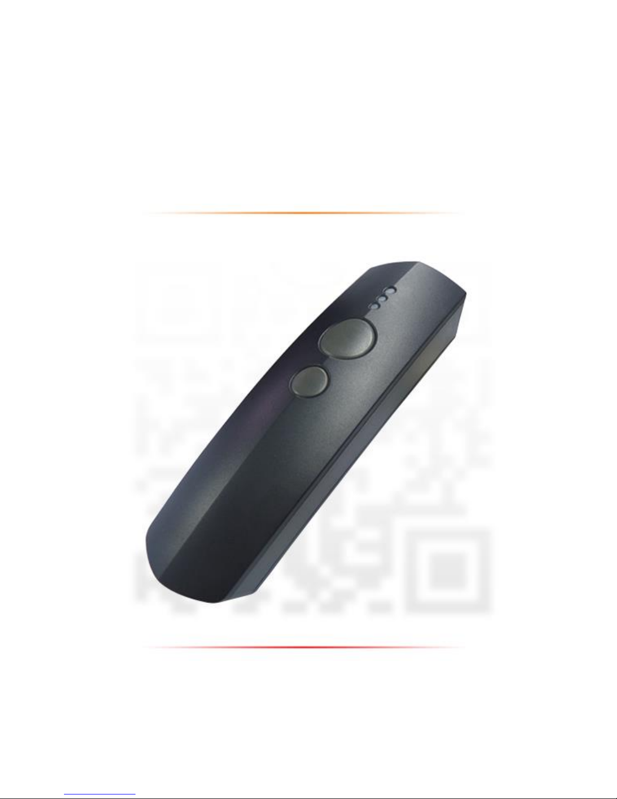
CM-2D600 User Manual
2D Bluetooth Barcode Scanner
Copy right 2015/01/19©
Page 2

II
Table of Contents
1. IMPORTANT NOTICE ___________________________________________________________ 1
1-1. FCC COMPLIANCE _____________________________________________________________ 2
1-2. CONFORMITY WITH TECHNICAL REGULATIONS FOR SPECIFIED RADIO EQUIPMENT IN JAPAN ____________ 2
1-3. NATIONAL COMMUNICATION COMMISSION _______________________________________ 2
1-4. ROHS COMPLIANCE ____________________________________________________________ 3
1-5. SAFETY PRECAUTION ___________________________________________________________ 3
2. INTRODUCTION ______________________________________________________________ 5
2-1. PRODUCT FEATURES____________________________________________________________ 6
2-2. PRODUCT SPECIFICATION ________________________________________________________ 6
2-3. PACKAGE INFORMATION _________________________________________________________ 7
2-4. SUPPORTED SYMBOLOGY ________________________________________________________ 8
2-5. PRODUCT OVERVIEW ___________________________________________________________ 9
2-6. MANUAL LAYOUT ____________________________________________________________ 10
2-7. PAGE LAYOUT _______________________________________________________________ 11
3. KNOWING YOUR SCANNER ____________________________________________________ 14
3-1. CONFIGURATION FLOWCHART ____________________________________________________ 15
3-2. LED & BEEPER INDICATIONS _____________________________________________________ 16
3-3. LEVERAGE YOUR SCANNER WITH BUTTON TRIGGERS _____________________________________ 17
3-3.1. SCAN ACTION _____________________________________________________________ 18
3-3.2. MODE SWITCH ____________________________________________________________ 18
3-3.3. TURN ON/OFF CHARGE _______________________________________________________ 18
3-3.4. DELETION OF ONE SINGLE DATA _________________________________________________ 18
3-3.5. DELETION OF ALL TRANSMITTED DATA _____________________________________________ 19
3-3.6. TRANSMISSION OF SAVED BARCODE ______________________________________________ 19
3-3.7. PAIRING WITH BLUETOOTH DEVICES ______________________________________________ 19
4. QUICK START _______________________________________________________________ 20
4-1. CONFIGURATION FLOWCHART ____________________________________________________ 21
4-2. SET UP YOUR SCANNER _________________________________________________________ 21
4-2-1. OPERATION MODE __________________________________________________________ 21
Page 3

III
Table of Contents
4-2-2. OUTPUT INTERFACE IN CABLE MODE ______________________________________________ 22
4-3. BASIC SCANNER OPERATIONS ____________________________________________________ 22
4-3-1. MODE SWITCH ____________________________________________________________ 22
4-3-2. TRANSMIT ALL BARCODE DATA __________________________________________________ 23
4-3-3. CLEAR ALL SAVED BARCODE DATA ________________________________________________ 23
4-3-4. CLEAR ONE SINGLE BARCODE DATA _______________________________________________ 23
4-3-5. AUTO-DELETE ALL TRANSMITTED DATA ____________________________________________ 24
4-3-6. ATTEMPT FIRMWARE UPDATE __________________________________________________ 24
4-4. HOW TO MAKE YOUR SCANNER WORK WITH BLUETOOTH DONGLE A-302 ______________________ 24
4-4-1. PAIR WITH BLUETOOTH DONGLE A-302 ____________________________________________ 24
4-4-2. DISABLE PAIRING FUNCTION____________________________________________________ 25
4-4-3. TYPE OF BLUETOOTH CONNECTION _______________________________________________ 25
5. ESTABLISH A BLUETOOTH CONNECTION __________________________________________ 26
5-1. BLUETOOTH CONNECTION REFERENCE CHART _________________________________________ 27
5-2. SET UP YOUR OWN BLUETOOTH CONNECTION _________________________________________ 28
5-2-1. SLAVE CONNECTION MODE ____________________________________________________ 28
5-2-2. MASTER CONNECTION MODE __________________________________________________ 36
5-2-3. HID CONNECTION MODE _____________________________________________________ 44
5-2-4. IOS CONNECTION MODE ______________________________________________________ 51
5-2-5. BLUETOOTH DONGLE A303 CONNECTION MODE _____________________________________ 57
5-2-6. BLUETOOTH DONGLE A302 CONNECTION MODE _____________________________________ 65
6. GENERAL CONFIGURATION ____________________________________________________ 72
6-1. HOST INTERFACE _____________________________________________________________ 73
6-1-1. RESTORE THE SETTING________________________________________________________ 73
6-1-2. RESTORE THE SYMBOLOGY SETTING _______________________________________________ 73
6-1-3. RETRIEVE FIRMWARE INFORMATION ______________________________________________ 73
6-1-4. ABORT THE CONFIGURATION ___________________________________________________ 73
6-1-5. UPDATE FIRMWARE _________________________________________________________ 73
6-1-6. ENABLE/DISABLE AUTOMATIC BATTERY CHARGER _____________________________________ 74
6-1-7. BLUETOOTH PAIRING _________________________________________________________ 74
6-2. SYSTEM CONTROL ____________________________________________________________ 74
6-2-1. AVAILABLE OPERATION MODES __________________________________________________ 74
6-2-2. SET DATE FORMAT __________________________________________________________ 75
6-2-3. SET TIME FORMAT __________________________________________________________ 76
Page 4

IV
Table of Contents
6-2-4. SET CHARGE RATE __________________________________________________________ 76
6-2-5. SET THE WORKFLOW OF OPERATION MODES SWITCH ___________________________________ 76
6-2-6. ENABLE/DISABLE BUZZER _____________________________________________________ 77
6-2-7. SET THE WARNING BUZZER VOLUME ______________________________________________ 77
6-2-8. ENABLE/DISABLE VIBRATOR ____________________________________________________ 77
6-2-9. ENABLE/DISABLE HEADER _____________________________________________________ 78
6-2-10. ENABLE/DISABLE SERIAL NUMBER INFO IN THE HEADER _________________________________ 78
6-2-11. ENABLE/DISABLE DATE INFO IN THE HEADER ________________________________________ 78
6-2-12. ENABLE/DISABLE TIME INFO IN THE HEADER ________________________________________ 79
6-2-13. ENABLE/DISABLE RECORD COUNT INFO IN THE HEADER _________________________________ 79
6-2-14. ENABLE/DISABLE FOOTER _____________________________________________________ 79
6-2-15. ENABLE/DISABLE SERIAL NUMBER INFO IN THE FOOTER _________________________________ 80
6-2-16. ENABLE/DISABLE DATE INFO IN THE FOOTER _________________________________________ 80
6-2-17. ENABLE/DISABLE TIME INFO IN THE FOOTER _________________________________________ 80
6-2-18. ENABLE/DISABLE RECORD COUNT INFO IN THE FOOTER _________________________________ 81
6-2-19. SET DATE & TIME ___________________________________________________________ 81
6-2-20. SET DATE SEPARATOR ________________________________________________________ 82
6-2-21. SET TIME SEPARATOR ________________________________________________________ 82
6-2-22. SET TIME-OUT PERIOD FOR CONFIGURATION MODE ___________________________________ 83
6-2-23. SET HEADER INFORMATION ____________________________________________________ 84
6-2-24. SET FOOTER INFORMATION ____________________________________________________ 85
6-3. SCANNER COMMANDS _________________________________________________________ 85
6-3-1. SET <DLE> ESCAPE CHARACTER _________________________________________________ 86
6-3-2. SET <CMD> ESCAPE CHARACTER ________________________________________________ 87
6-3-3. SET <BAR> ESCAPE CHARACTER _________________________________________________ 88
6-3-4. SET <STX> ESCAPE CHARACTER _________________________________________________ 89
6-3-5. SET <ETX> ESCAPE CHARACTER _________________________________________________ 90
7. SETTING UP YOUR OPERATION MODES ___________________________________________ 91
7-1. OUTPUT STRING STRUCTURE _____________________________________________________ 92
7-2. CABLE MODE _______________________________________________________________ 93
7-2-1. OUTPUT INTERFACE OPTIONS ___________________________________________________ 93
7-2-1-1. Set Data Transfer Rate for SPP ____________________________________________ 93
7-2-1-2. Set Length of Stop Bit for SPP ____________________________________________ 93
7-2-1-3. Set Parity Check for SPP _________________________________________________ 94
7-2-1-4. Set Communication Protocol for SPP _______________________________________ 94
7-2-1-5. Enable/Disable <STX> and <ETX> Escape Characters for SPP ____________________ 95
Page 5

V
Table of Contents
7-2-1-6. Enable/Disable <BAR> and <CMD> Escape Characters for SPP ___________________ 95
7-2-1-7. Enable/Disable Command Mode for SPP ____________________________________ 95
7-2-1-8. Set Baud Rate for SPP ___________________________________________________ 96
7-2-1-9. Set Transfer Count for Time Delay for SPP ___________________________________ 97
7-2-1-10. Set Time Delay for a Digit for SPP __________________________________________ 98
7-2-1-11. Set Time Delay for a Record for SPP ________________________________________ 99
7-2-1-12. Set Time Delay for a Specified Digit for SPP _________________________________ 100
7-2-1-13. Set Timeout for SPP ___________________________________________________ 101
7-2-1-14. Set Retransmission Count for SPP ________________________________________ 102
7-2-1-15. Set ACK Timeout for SPP _______________________________________________ 103
7-2-1-16. Set Caps Lock Setting for HID ____________________________________________ 103
7-2-1-17. Enable/Disable Num Lock for HID ________________________________________ 104
7-2-1-18. Enable/Disable Caps Lock Emulation ______________________________________ 105
7-2-1-19. Set IMEs for HID ______________________________________________________ 105
7-2-1-20. Set Character Coding Method for HID _____________________________________ 106
7-2-1-21. Set Operating Syetem for HID ___________________________________________ 106
7-2-1-22. Set Transfer Count for Time Delay for HID __________________________________ 107
7-2-1-23. Set Time Delay for a Digit for HID _________________________________________ 108
7-2-1-24. Set Time Delay for a Record for HID _______________________________________ 109
7-2-1-25. Set Time Delay for a Specified Digit for HID _________________________________ 110
7-2-1-26. Set Timeout for HID ___________________________________________________ 111
7-2-2. SCANNER OPTIONS _________________________________________________________ 112
7-2-2-1. Set Scan Mode _______________________________________________________ 112
7-2-2-2. Set Output Interface ___________________________________________________ 112
7-2-2-3. Set Small Trigger Functionality ___________________________________________ 113
7-2-2-4. Set Composite Triggers Functionality ______________________________________ 113
7-2-2-5. Set Good Read Buzzer Volume ___________________________________________ 114
7-2-2-6. Set Warning Buzzer Volume _____________________________________________ 114
7-2-2-7. Set Mode Event Buzzer Volume __________________________________________ 115
7-2-2-8. Enabl/Disable Battery Charge ___________________________________________ 115
7-2-2-9. Enable/Disable Good Read Vibrator_______________________________________ 115
7-2-2-10. Enable/Disable Warning Vibrator _________________________________________ 116
7-2-2-11. Enable/Disable Mode Event Vibrator ______________________________________ 116
7-2-2-12. Enable/Disable Good Read Buzzer ________________________________________ 116
7-2-2-13. Enable/Disable Warning Buzzer __________________________________________ 117
7-2-2-14. Enable/Disable Mode Event Buzzer _______________________________________ 117
7-2-2-15. Set Good Read Buzzer Frequency ________________________________________ 118
7-2-2-16. Set Good Read Buzzer Duration __________________________________________ 118
Page 6

VI
Table of Contents
7-2-2-17. Set Hibernation Duration _______________________________________________ 119
7-2-2-18. Set Activation Duration ________________________________________________ 120
7-2-2-19. Set Idle Duration ______________________________________________________ 121
7-2-2-20. Set Standby Duration __________________________________________________ 122
7-2-3. OUTPUT EDITING OPTIONS ___________________________________________________ 123
7-2-3-1. Enable/Disable Preamble Code __________________________________________ 123
7-2-3-2. Enable/Disable Postamble Code _________________________________________ 123
7-2-3-3. Enable/Disable Prefix Code _____________________________________________ 124
7-2-3-4. Enable/Disable Suffix Code _____________________________________________ 124
7-2-3-5. Enable/Disable Code ID ________________________________________________ 124
7-2-3-6. Set Position of Code ID _________________________________________________ 125
7-2-3-7. Enable/Disable Barcode Length Info ______________________________________ 125
7-2-3-8. Enable/Disable Symbology Name ________________________________________ 125
7-2-3-9. Enable/Disable Control Code Info ________________________________________ 126
7-2-3-10. Enable/Disable Delimiter _______________________________________________ 126
7-2-3-11. Set Timestamps Positioning _____________________________________________ 126
7-2-3-12. Enable/Disable Date Information _________________________________________ 127
7-2-3-13. Enable/Disable Time Information ________________________________________ 127
7-2-3-14. Set Type of Case Conversion ____________________________________________ 127
7-2-3-15. Set Delimiter Between Time/Date Stamps and Barcode Data ___________________ 128
7-2-3-16. Set Delimiter Between Date and Time Stamps ______________________________ 128
7-2-3-17. Set Preamble Code ____________________________________________________ 129
7-2-3-18. Set Postamble Code ___________________________________________________ 130
7-2-3-19. Set Prefix Code _______________________________________________________ 131
7-2-3-20. Set Suffix Code _______________________________________________________ 132
7-3. MEMORY MODE ____________________________________________________________ 133
7-3-1. SCANNER OPTIONS _________________________________________________________ 133
7-3-1-1 Set Scan Mode _______________________________________________________ 133
7-3-1-2 Set Output Interface ___________________________________________________ 133
7-3-1-3 Set Small Trigger Functionality ___________________________________________ 134
7-3-1-4 Set Composite Triggers Functionality ______________________________________ 135
7-3-1-5 Enable/Disable Battery Charge __________________________________________ 135
7-3-1-6 Set Good Read Buzzer Volume ___________________________________________ 135
7-3-1-7 Set Warning Buzzer Volume _____________________________________________ 136
7-3-1-8 Set Mode Event Buzzer Volume __________________________________________ 136
7-3-1-9 Enable/Disable Good Read Vibrator_______________________________________ 137
7-3-1-10 Enable/Disable Warning Vibrator _________________________________________ 137
7-3-1-11 Enable/Disable Mode Event Vibrator ______________________________________ 137
Page 7

VII
Table of Contents
7-3-1-12 Enable/Disable Good Read Buzzer ________________________________________ 138
7-3-1-13 Enable/Disable Warning Buzzer __________________________________________ 138
7-3-1-14 Enable/Disable Mode Buzzer ____________________________________________ 138
7-3-1-15 Set Data Transmission Unit______________________________________________ 139
7-3-1-16 Deletion of Transmitted Data ____________________________________________ 139
7-3-1-17 Enable/Disable Header Info _____________________________________________ 139
7-3-1-18 Enable/Disable Footer Info ______________________________________________ 140
7-3-1-19. Set Good Read Buzzer Frequency ________________________________________ 140
7-3-1-20. Set Good Read Buzzer Duration __________________________________________ 140
7-3-1-21. Set Hibernation Duration _______________________________________________ 141
7-3-1-22. Set Activation Duration ________________________________________________ 142
7-3-1-23. Set Idle Duration ______________________________________________________ 143
7-3-1-24. Set Standby Duration __________________________________________________ 144
7-3-2. OUTPUT EDITING OPTIONS ___________________________________________________ 145
7-3-2-1. Enable/Disable Preamble Code __________________________________________ 145
7-3-2-2. Enable/Disable Postamble Code _________________________________________ 145
7-3-2-3. Enable/Disable Prefix Code _____________________________________________ 146
7-3-2-4. Enable/Disable Suffix Code _____________________________________________ 146
7-3-2-5. Enable/Disable Code ID ________________________________________________ 146
7-3-2-6. Set Position of Code ID _________________________________________________ 147
7-3-2-7. Enable/Disable Barcode Length Info ______________________________________ 147
7-3-2-8. Enable/Disable Symbology Name ________________________________________ 147
7-3-2-9. Enable/Disable Control Code Info ________________________________________ 148
7-3-2-10. Enable/Disable Delimiter _______________________________________________ 148
7-3-2-11. Set Timestamps Positioning _____________________________________________ 148
7-3-2-12. Enable/Disable Date Information _________________________________________ 149
7-3-2-13. Enable/Disable Time Information ________________________________________ 149
7-3-2-14. Reject Same _________________________________________________________ 149
7-3-2-15. Set Type of Case Conversion ____________________________________________ 150
7-3-2-16. Set Delimiter Between Date/Time Stamps and Barcode Data ___________________ 150
7-3-2-17. Set Delimiter Between Date and Time Stamps ______________________________ 151
7-3-2-18. Set Preamble Code ____________________________________________________ 151
7-3-2-19. Set Postamble Code ___________________________________________________ 152
7-3-2-20. Set Prefix Code _______________________________________________________ 153
7-3-2-21. Set Suffix Code _______________________________________________________ 153
7-4. BLUETOOTH MODE __________________________________________________________ 155
7-4-1. OUTPUT INTERFACE OPTIONS __________________________________________________ 155
7-4-1-1. Set Communication Protocol for SPP ______________________________________ 155
Page 8

VIII
Table of Contents
7-4-1-2. Enable/Disable <STX> and <ETX> Escape Characters for SPP ___________________ 156
7-4-1-3. Enable/Disable <BAR> and <CMD> Escape Characters for SPP __________________ 156
7-4-1-4. Enable/Disable Command Mode for SPP ___________________________________ 156
7-4-1-5. Set Transfer Count for Time Delay for SPP __________________________________ 157
7-4-1-6. Set Time Delay for a Digit for SPP _________________________________________ 158
7-4-1-7. Set Time Delay for a Record for SPP _______________________________________ 159
7-4-1-8. Set Time Delay for a Specified Digit for SPP _________________________________ 160
7-4-1-9. Set Timeout for SPP ___________________________________________________ 161
7-4-1-10. Set Retransmission Count for SPP ________________________________________ 162
7-4-1-11. Set ACK Timeout for SPP _______________________________________________ 163
7-4-1-12. Set Caps Lock Setting for HID ____________________________________________ 163
7-4-1-13. Enable/Disable Num Lock for HID ________________________________________ 164
7-4-1-14. Set IMEs for HID ______________________________________________________ 165
7-4-1-15. Set Character Coding Method for HID _____________________________________ 166
7-4-1-16. Set Transfer Count for Time Delay for HID __________________________________ 166
7-4-1-17. Set Time Delay for a Digit for HID _________________________________________ 167
7-4-1-18. Set Time Delay for a Record for HID _______________________________________ 168
7-4-1-19. Set Time Delay for a Specified Digit for HID _________________________________ 169
7-4-1-20. Set Timeout for HID ___________________________________________________ 170
7-4-1-21. Set PIN Code _________________________________________________________ 171
7-4-1-22. Set Bluetooth address _________________________________________________ 172
7-4-1-23. Set Machine Name ____________________________________________________ 173
7-4-1-24. Set Bluetooth address for Dongle A302/A303 _______________________________ 174
7-4-1-25. Set Machine Name for Dongle A302/A303 _________________________________ 175
7-4-2. SCANNER OPTIONS _________________________________________________________ 176
7-4-2-1. Set Scan Mode _______________________________________________________ 176
7-4-2-2. Set Output Interface ___________________________________________________ 176
7-4-2-3. Set Small Trigger Functionality ___________________________________________ 177
7-4-2-4. Set Composite Triggers Functionality ______________________________________ 177
7-4-2-5. Enable/Disable Battery Charge __________________________________________ 178
7-4-2-6. Set Good Read Buzzer Volume ___________________________________________ 178
7-4-2-7. Set Warning Buzzer Volume _____________________________________________ 178
7-4-2-8. Set Mode Event Buzzer Volume __________________________________________ 179
7-4-2-9. Enable/Disable Good Read Vibrator_______________________________________ 179
7-4-2-10. Enable/Disable Warning Vibrator _________________________________________ 180
7-4-2-11. Enable/Disable Mode Event Vibrator ______________________________________ 180
7-4-2-12. Enable/Disable Good Read Buzzer ________________________________________ 180
7-4-2-13. Enable/Disable Warning Buzzer __________________________________________ 181
Page 9

IX
Table of Contents
7-4-2-14. Enable/Disable Mode Buzzer ____________________________________________ 181
7-4-2-15. Set Pairing Timeout ___________________________________________________ 182
7-4-2-16. Set Good Read Buzzer Frequency ________________________________________ 182
7-4-2-17. Set Good Read Buzzer Duration __________________________________________ 183
7-4-2-18. Set Hibernation Duration _______________________________________________ 184
7-4-2-19. Set Activation Duration ________________________________________________ 185
7-4-2-20. Set Idle Duration ______________________________________________________ 185
7-4-2-21. Set Standby Duration __________________________________________________ 186
7-4-3. OUTPUT EDITING OPTIONS ___________________________________________________ 187
7-4-3-1. Enable/Disable Preamble Code __________________________________________ 187
7-4-3-2. Enable/Disable Postamble Code _________________________________________ 187
7-4-3-3. Enable/Disable Prefix Code _____________________________________________ 188
7-4-3-4. Enable/Disable Suffix Code _____________________________________________ 188
7-4-3-5. Enable/Disable Code ID ________________________________________________ 188
7-4-3-6. Set Position of Code ID _________________________________________________ 189
7-4-3-7. Enable/Disable Barcode Length Info ______________________________________ 189
7-4-3-8. Enable/Disable Symbology Name ________________________________________ 189
7-4-3-9. Enable/Disable Control Code Info ________________________________________ 190
7-4-3-10. Enable/Disable Delimiter _______________________________________________ 190
7-4-3-11. Set Timestamps Positioning _____________________________________________ 190
7-4-3-12. Enable/Disable Date Information _________________________________________ 191
7-4-3-13. Enable/Disable Time Information ________________________________________ 191
7-4-3-14. Set Type of Case Conversion ____________________________________________ 191
7-4-3-15. Set Delimiter Between Date/Time Stamps and Barcode Data ___________________ 192
7-4-3-16. Set Delimiter Between Date and Time Stamps ______________________________ 192
7-4-3-17. Set Preamble Code ____________________________________________________ 193
7-4-3-18. Set Postamble Code ___________________________________________________ 194
7-4-3-19. Set Prefix Code _______________________________________________________ 194
7-4-3-20. Set Suffix Code _______________________________________________________ 195
8. CONFIGURING SYMBOLOGY __________________________________________________ 196
8-1. DEFAULT SETTING ___________________________________________________________ 197
8-2. AUPOST __________________________________________________________________ 198
8-2-1. ENABLE/DISABLE AUPOST ____________________________________________________ 198
8-2-2. SET CODE ID FOR AUPOST ____________________________________________________ 198
8-3. AZTEC ___________________________________________________________________ 199
8-3-1 ENABLE/DISABLE AZTEC _____________________________________________________ 199
Page 10

X
Table of Contents
8-3-2 CONFIGURE LENGTH QUALIFICATION _____________________________________________ 199
8-3-3 SET CODE ID FOR AZTEC _____________________________________________________ 200
8-3-4 SET LENGTH SCALE _________________________________________________________ 200
8-4. UKPOST _________________________________________________________________ 201
8-4-1. ENABLE/DISABLE UKPOST ____________________________________________________ 201
8-4-2. TRANSMIT CHECK DIGIT _____________________________________________________ 202
8-4-3. SET CODE ID FOR UKPOST ____________________________________________________ 202
8-5. CAPOST __________________________________________________________________ 203
8-5-1. ENABLE/DISABLE CAPOST ____________________________________________________ 203
8-5-2. SET CODE ID FOR CAPOST ____________________________________________________ 203
8-6. CODABAR ________________________________________________________________ 204
8-6-1. ENABLE/DISABLE CODABAR ___________________________________________________ 204
8-6-2. CONFIGURE START/STOP CHARACTERS ____________________________________________ 204
8-6-3. CONFIGURE CONCATENATION MODE _____________________________________________ 205
8-6-4. ENABLE/DISABLE CONCATENATION ______________________________________________ 205
8-6-5. ENABLE/DISABLE CLSI LIBRARY SYSTEM ___________________________________________ 205
8-6-6. TRANSMIT CHECK DIGIT _____________________________________________________ 206
8-6-7. VERIFY CHECK DIGIT ________________________________________________________ 206
8-6-8. CONFIGURE LENGTH QUALIFICATION _____________________________________________ 206
8-6-9. SET CODE ID FOR CODABAR ___________________________________________________ 207
8-6-10. SET LENGTH SCALE _________________________________________________________ 207
8-7. CODABLOCK _______________________________________________________________ 209
8-7-1. ENABLE/DISABLE CODABLOCK A ________________________________________________ 209
8-7-2. ENABLE/DISABLE CODABLOCK F ________________________________________________ 209
8-7-3. SET CODE ID FOR CODABLOCK A _______________________________________________ 209
8-7-4. SET CODE ID FOR CODABLOCK F ________________________________________________ 210
8-8. CODE11 _________________________________________________________________ 211
8-8-1. ENABLE/DISABLE CODE11 ____________________________________________________ 211
8-8-2. TRANSMIT CHECK DIGIT _____________________________________________________ 211
8-8-3. VERIFY CHECK DIGIT ________________________________________________________ 211
8-8-4. CONFIGURE LENGTH QUALIFICATION _____________________________________________ 212
8-8-5. SET CODE ID FOR CODE11 ____________________________________________________ 212
8-8-6. SET LENGTH SCALE _________________________________________________________ 213
8-9. CODE39 _________________________________________________________________ 214
8-9-1. ENABLE/DISABLE CODE39 ____________________________________________________ 214
8-9-2. TRANSMIT START/STOP DELIMITERS _____________________________________________ 214
8-9-3. TRUNCATE LEADING ZEROS ___________________________________________________ 214
8-9-4. TRANSMIT CHECK DIGIT _____________________________________________________ 215
Page 11

XI
Table of Contents
8-9-5. CONFIGURE CHECKSUM TYPE __________________________________________________ 215
8-9-6. SET CODE ID FOR CODE39 ____________________________________________________ 215
8-9-7. SET LENGTH SCALE _________________________________________________________ 216
8-9-8. REMOVE LEADING CHARACTERS FOR CODE39 _______________________________________ 217
8-9-9. REMOVE TRAILING CHARACTERS FOR CODE39 ______________________________________ 218
8-10. CODE93 _________________________________________________________________ 219
8-10-1. ENABLE/DISABLE CODE93 ____________________________________________________ 219
8-10-2. CONFIGURE LENGTH QUALIFICATION _____________________________________________ 219
8-10-3. SET CODE ID FOR CODE93 ____________________________________________________ 219
8-10-4. SET LENGTH SCALE _________________________________________________________ 220
8-11. CODE128 ________________________________________________________________ 222
8-11-1. ENABLE/DISABLE CODE128 ___________________________________________________ 222
8-11-2. ENABLE/DISABLE ISBT128 ___________________________________________________ 222
8-11-3. ENABLE/DISABLE GS1-128 ___________________________________________________ 222
8-11-4. READ TOLERANCE __________________________________________________________ 222
8-11-5. ENABLE/DISABLE AIM ID FOR GS1-128 __________________________________________ 223
8-11-6. ENABLE/DISABLE GTIN PROCESSING _____________________________________________ 223
8-11-7. VERIFY CHECK DIGIT ________________________________________________________ 223
8-11-8. CONFIGURE LENGTH QUALIFICATION _____________________________________________ 224
8-11-9. TRANSMIT AIM IDENTIFIER ___________________________________________________ 224
8-11-10. TRANSMIT APPLICATION IDENTIFIER______________________________________________ 225
8-11-11. SET DECODING SCHEME FOR UNCONVENTIONAL GS1-128 ______________________________ 225
8-11-12. SET SEPARATOR FOR CODE128 _________________________________________________ 226
8-11-13. SET LENGTH SCALE _________________________________________________________ 227
8-11-14. SET CODE ID FOR CODE128 ___________________________________________________ 228
8-11-15. SET CODE ID FOR GS1-128 ___________________________________________________ 228
8-12. DATA MATRIX ______________________________________________________________ 230
8-12-1. ENABLE/DISABLE DATA MATRIX ________________________________________________ 230
8-12-2. ENABLE/DISABLE MIRRORED DATA MATRIX ________________________________________ 230
8-12-3. CONFIGURE LENGTH QUALIFICATION _____________________________________________ 230
8-12-4. SET CODE ID FOR DATA MATRIX ________________________________________________ 231
8-12-5. SET LENGTH SCALE _________________________________________________________ 231
8-13. NI POST __________________________________________________________________ 233
8-13-1. ENABLE/DISABLE NI POST ____________________________________________________ 233
8-13-2. SET CODE ID FOR NI POST ____________________________________________________ 233
8-14. WORLD PRODUCT CODE _______________________________________________________ 234
8-14-1. ENABLE/DISABLE UPC-A ____________________________________________________ 234
8-14-2. ENABLE/DISABLE UPC-E _____________________________________________________ 234
Page 12

XII
Table of Contents
8-14-3. ENABLE/DISABLE EAN-13 ____________________________________________________ 234
8-14-4. ENABLE/DISABLE EAN-8 _____________________________________________________ 235
8-14-5. CONVERT UPC-A TO EAN-13 _________________________________________________ 235
8-14-6. TRANSMIT CHECK DIGIT FOR UPC-A _____________________________________________ 235
8-14-7. ENABLE/DISABLE UPC-E1 ____________________________________________________ 235
8-14-8. CONVERT UPC-E TO UPC-A __________________________________________________ 236
8-14-9. TRANSMIT CHECK DIGIT FOR UPC-E _____________________________________________ 236
8-14-10. CONVERT EAN-13 TO ISBN ___________________________________________________ 236
8-14-11. CONVERT EAN-13 TO ISMN __________________________________________________ 236
8-14-12. CONVERT EAN-13 TO ISSN ___________________________________________________ 237
8-14-13. TRANSMIT CHECK DIGIT FOR EAN-13 ____________________________________________ 237
8-14-14. CONVERT EAN-8 TO EAN-13 _________________________________________________ 237
8-14-15. TRANSMIT CHECK DIGIT FOR EAN-8 _____________________________________________ 237
8-14-16. ENABLE/DISABLE 2-DIGIT ADD-ON SYMBOL ________________________________________ 238
8-14-17. ENABLE/DISABLE 5-DIGIT ADD-ON SYMBOL ________________________________________ 238
8-14-18. ENABLE/DISABLE GTIN PROCESSING _____________________________________________ 238
8-14-19. SET CODE ID FOR UPC-A ____________________________________________________ 239
8-14-20. SET CODE ID FOR UPC-E _____________________________________________________ 239
8-14-21. SET CODE ID FOR EAN-13 ___________________________________________________ 240
8-14-22. SET CODE ID FOR EAN-8 ____________________________________________________ 241
8-15. GS1 COMPOSITE ____________________________________________________________ 242
8-15-1. ENABLE/DISABLE COMPOSITE CODE A/B __________________________________________ 242
8-15-2. ENABLE/DISABLE COMPOSITE CODE C ____________________________________________ 242
8-15-3. TRANSMIT LINEAR COMPONENTS _______________________________________________ 242
8-15-4. TRANSMIT AIM IDENTIFIER ___________________________________________________ 242
8-15-5. TRANSMIT APPLICATION IDENTIFIER______________________________________________ 243
8-15-6. UPC/EAN MESSAGE DECODING ________________________________________________ 243
8-15-7. SET CODE ID FOR COMPOSITE CODE A/B __________________________________________ 244
8-15-8. SET CODE ID FOR COMPOSITE CODE C ____________________________________________ 244
8-16. GS1 DATABAR _____________________________________________________________ 246
8-16-1. ENABLE/DISABLE GS1 DATABAR OMNIDIRECTIONAL __________________________________ 246
8-16-2. ENABLE/DISABLE GS1 DATABAR LIMITED __________________________________________ 246
8-16-3. ENABLE/DISABLE GS1 DATABAR EXPANDED ________________________________________ 246
8-16-4. TRANSMIT AIM IDENTIFIER ___________________________________________________ 247
8-16-5. TRANSMIT APP IDENTIFIER ___________________________________________________ 247
8-16-6. SET CODE ID FOR GS1 DATABAR OMNIDIRECTIONAL __________________________________ 247
8-16-7. SET CODE ID FOR GS1 DATABAR LIMITED _________________________________________ 248
8-16-8. SET CODE ID FOR GS1 DATABAR EXPANDED ________________________________________ 249
Page 13

XIII
Table of Contents
8-17. INFO MAIL ________________________________________________________________ 250
8-17-1. ENABLE/DISABLE INFO MAIL __________________________________________________ 250
8-17-2. SET CODE ID FOR INFO MAIL __________________________________________________ 250
8-18. INTELLIGENT MAIL ___________________________________________________________ 251
8-18-1. ENABLE/DISABLE INTELLIGENT MAIL _____________________________________________ 251
8-18-2. SET CODE ID FOR INTELLIGENT MAIL _____________________________________________ 251
8-19. INTERLEAVE25 _____________________________________________________________ 252
8-19-1. ENABLE/DISABLE INTERLEAVE25 ________________________________________________ 252
8-19-2. READ TOLERANCE __________________________________________________________ 252
8-19-3. CONFIGURE CHECKSUM TYPE __________________________________________________ 252
8-19-4. TRANSMIT CHECK DIGIT _____________________________________________________ 253
8-19-5. CONFIGURE LENGTH QUALIFICATION _____________________________________________ 253
8-19-6. SET CODE ID FOR INTERLEAVE25 _______________________________________________ 253
8-19-7. SET LENGTH SCALE _________________________________________________________ 254
8-20. JP POST __________________________________________________________________ 256
8-20-1. ENABLE/DISABLE JP POST ____________________________________________________ 256
8-20-2. TRANSMIT CHECK DIGIT _____________________________________________________ 256
8-20-3. SET CODE ID FOR JP POST ____________________________________________________ 256
8-21. MATRIX 25 _______________________________________________________________ 257
8-21-1. ENABLE/DISABLE MATRIX 25 __________________________________________________ 257
8-21-2. CONFIGURE LENGTH QUALIFICATION _____________________________________________ 257
8-21-3. SET CODE ID FOR MATRIX 25 __________________________________________________ 258
8-21-4. SET LENGTH SCALE _________________________________________________________ 258
8-22. MAXICODE________________________________________________________________ 260
8-22-1. ENABLE/DISABLE MAXICODE __________________________________________________ 260
8-22-2. SET CODE ID FOR MAXICODE __________________________________________________ 260
8-23. MSI ____________________________________________________________________ 261
8-23-1 ENABLE/DISABLE MSI ______________________________________________________ 261
8-23-2 CONFIGURE CHECKSUM TYPE __________________________________________________ 261
8-23-3 TRANSMIT CHECK DIGIT _____________________________________________________ 261
8-23-4 CONFIGURE LENGTH QUALIFICATION _____________________________________________ 262
8-23-5 SET CODE ID FOR MSI ______________________________________________________ 262
8-23-6 SET LENGTH SCALE _________________________________________________________ 263
8-24. PDF417 _________________________________________________________________ 264
8-24-1. ENABLE/DISABLE PDF417 ___________________________________________________ 264
8-24-2. ENABLE/DISABLE MICRO PDF417 ______________________________________________ 264
8-24-3. TRANSMIT CHECK DIGIT _____________________________________________________ 264
8-24-4. SET CODE ID FOR PDF417 ___________________________________________________ 264
Page 14

XIV
Table of Contents
8-24-5. SET CODE ID FOR MICRO PDF 417 ______________________________________________ 265
8-25. PLANET _________________________________________________________________ 266
8-25-1. ENABLE/DISABLE PLANET ___________________________________________________ 266
8-25-2. TRANSMIT CHECK DIGIT _____________________________________________________ 266
8-25-3. SET CODE ID FOR PLANET ___________________________________________________ 266
8-26. PLESSEY __________________________________________________________________ 268
8-26-1. ENABLE/DISABLE PLESSEY ____________________________________________________ 268
8-26-2. TRANSMIT CHECK DIGIT _____________________________________________________ 268
8-26-3. CONFIGURE LENGTH QUALIFICATION _____________________________________________ 268
8-26-4. SET CODE ID FOR PLESSEY ____________________________________________________ 269
8-26-5. SET LENGTH SCALE _________________________________________________________ 269
8-27. POSTNET ________________________________________________________________ 271
8-27-1. ENABLE/DISABLE POSTNET __________________________________________________ 271
8-27-2. TRANSMIT CHECK DIGIT _____________________________________________________ 271
8-27-3. SET CODE ID FOR POSTNET __________________________________________________ 271
8-28. QR CODE _________________________________________________________________ 273
8-28-1. ENABLE/DISABLE QR CODE ___________________________________________________ 273
8-28-2. ENABLE/DISABLE MICRO QR CODE ______________________________________________ 273
8-28-3. ENABLE/DISABLE QR CODE MODEL 1 ____________________________________________ 273
8-28-4. ENABLE/DISABLE INVERSED QR CODE ____________________________________________ 273
8-28-5. CONFIGURE LENGTH QUALIFICATION _____________________________________________ 274
8-28-6. SET CODE ID FOR QR CODE ___________________________________________________ 274
8-28-7. SET LENGTH SCALE _________________________________________________________ 275
8-29. INDUSTRIAL 25 _____________________________________________________________ 277
8-29-1. ENABLE/DISABLE INDUSTRIAL 25 _______________________________________________ 277
8-29-2. CONFIGURE CHECKSUM TYPE __________________________________________________ 277
8-29-3. TRANSMIT CHECK DIGIT _____________________________________________________ 277
8-29-4. CONFIGURE LENGTH QUALIFICATION _____________________________________________ 277
8-29-5. SET CODE ID FOR INDUSTRIAL 25 _______________________________________________ 278
8-29-6. SET LENGTH SCALE _________________________________________________________ 278
8-30. SWEDEN POST _____________________________________________________________ 280
8-30-1. ENABLE/DISABLE SWEDEN POST ________________________________________________ 280
8-30-2. SET CODE ID FOR SWEDEN POST________________________________________________ 280
8-31. TELEPEN _________________________________________________________________ 281
8-31-1. ENABLE/DISABLE TELEPEN ____________________________________________________ 281
8-31-2. CONFIGURE OUTPUT FORMAT _________________________________________________ 281
8-31-3. CONFIGURE LENGTH QUALIFICATION _____________________________________________ 281
8-31-4. SET CODE ID FOR TELEPEN ____________________________________________________ 282
Page 15

XV
Table of Contents
8-31-5. SET LENGTH SCALE _________________________________________________________ 282
8-32. TLC 39 __________________________________________________________________ 284
8-32-1. ENABLE/DISABLE TLC 39 ____________________________________________________ 284
8-32-2. SET SECURITY LEVEL FOR TLC 39 _______________________________________________ 284
8-32-3. SET CODE ID FOR TLC 39 ____________________________________________________ 285
APPENDIX A ___________________________________________________________________ 286
DECIMAL/ HEXADECIMAL TABLE _______________________________________________________ 286
ASCII CODE TABLE ________________________________________________________________ 287
APPENDIX B ___________________________________________________________________ 288
TEST CHART ____________________________________________________________________ 288
Page 16

Enter 1 End
*/$%ENTR* *ZEND*
Important Notices
1. Important Notice
In compliance with a number of International standards as well as reguations, CM-2D600 is a
highly qualified product at the technical and safety level. In this chapter enumerates the list of
regulations which CM-2D600 complies with for your reference.
Page 17
Enter 2 End
*/$%ENTR* *ZEND*
Important Notices
1-1. FCC Compliance
This device complies with part 15 of the FCC Rules. Operation is subject to the following
two conditions: (1) This device may not cause harmful interference, and (2) this device must
accept any interference received, including interference that may cause undesired operation.
This device has been tested and found to comply with the limits for a Class B digital device,
pursuant to Part 15 of the FCC Rules. These limits are designed to provide reasonable
protection against harmful interference in a residential installation. This equipment generates,
uses, and can radiate radio frequency energy, and, if not installed and used in accordance
with the instructions, may cause harmful interference to radio communications. However,
there is no guarantee that interference will not occur in a particular installation. If this
equipment does cause harmful interference to radio or television reception, which can be
determined by turning the equipment off and on, the user is encouraged to try to correct the
interference by one or more of the following measures:
Reorient or relocate the receiving antenna.
Increase the separation between the equipment and receiver.
Connect the equipment into an outlet on a circuit different from that to which the
receiver is connected.
1-2. Conformity with Technical Regulations for specified radio
equipment in Japan
Certificate Number: 204WW81000100
1-3. National Communication Commission
NCC Registration Number: NCC-RCB-05
Qualified serials number on device:
Page 18

Enter 3 End
*/$%ENTR* *ZEND*
Important Notices
1-4. RoHS Compliance
The RoHS directive mandates that producers of electrical or electronic equipment sold into
Europe must minimize or eliminate the following materials from their design, as they are
considered health risks:
1. Lead
2. Mercury
3. Cadmium
4. Hexavalent Chromium
5. Polybrominated biphenyls (PBB)
6. Polybrominated biphenyl ethers (PBDE)
Committed to the environment, CanMax Technology makes the necessary changes to our
products in order to comply with RoHS directive. This involves the process of converting the
non-compliant components (for instance, electronics, Pc Boards, etc.) of our products into
the compliant ones. We also improve the assembly processes to ensure the full compliance
with RoHS directive. The measures that we take in conformity with RoHS directive would
never cause any change in the product appearance, nor do they decrease functionality of the
product. Most importantly, our product still provides reliable and excellent product
performance as we promise.
1-5. Safety Precaution
Do not stare directly at light beams.
Do not directly touch the scanner window for reading performance might decrease if
the window is dirty or scratched.
Do not disassemble or modify the internal components from the scanner.
Do not expose the scanner to any flammable source.
Do not overcharge the battery.
Lithium-lon polymer Battery
The Lithium-ion polymer battery energy density is less than 400 Wh/L. Therefore,
PSE certification does not require in this product.
Page 19

Enter 4 End
*/$%ENTR* *ZEND*
Important Notices
The first, initial charge will take up four hours to fully charge your battery.
Battery Life time
Memory Mode: Approximately 18000 scans (5 sec/per scan)
Bluetooth Mode: Approximately 15000 scans (5 sec/per scan)
Do not assemble or disassemble the battery without technical support.
Do not use unspecified power adaptor to charge the battery.
During the charging process, if red color LED indicator keeps flashing rapidly,
terminate the charging, and return the scanner to authorized dealers.
Once battery leakage or abnormal odor occurs, terminate the current operation, and
return the scanner to authorized dealers.
Once batteries leak, avoid contact with skins or eyes. To clean up the battery leakage,
rinse the affected parts with fresh water, and consult the doctor immediately.
Page 20

Enter 5 End
*/$%ENTR* *ZEND*
Introduction
2. Introduction
Using this introductory chapter you will grasp physical aspects of CM-2D600 with regard to
the product appearance and specification. On top of it, the sections for Manual/Page layout
will enable you to locate the topics of your interest through the manal more efficiently.
Page 21

Enter 6 End
*/$%ENTR* *ZEND*
Introduction
2-1. Product Features
CM-2D600 is a select barcode scanner of versatility in aim to provide scanning accuracy and
enhance working efficiency. Not only does its vast storage capacity of 4M Byte flash
memory suffice you to store up as much barcodes as you need, but also you are able to well
handle all sorts of tasks with three-in-one multi-functionality provided. Besides, through the
lightweight and stylish design of CM-2D600, a grip of it will have you experience a
comfortable touch which eases physical tension due to a laborious task. Overall, from a great
diversity of scanning preferences to high compatibility with different Bluetooth devices and
a broad support of multiple symbology, the ergonomic scanner will definitely leave you
extraordinary impressions in your scanning activities.
2-2. Product Specification
Model NO.
CM-2D600
Under cable mode interface
USB COM,USB HID
Supported barcode
1D: EAN/UPC, RSS, Code 39, Code 128, UCC/EAN 128,
ISBN, ISBT, Interleaved, Matrix, Industrial and Standard
2 of 5, Codabar, Code 93/93i, Code 11, MSI, Plessey,
Telepen, Postal Codes
2D: Data Matrix, PDF417, Micro PDF 417, Maxicode,
QR, Aztec, EAN, UCC composite
Optical Resolution
752(H)x480(V) pixels, 256 gray levels
PCS
D25%
Scan Rate
2D: 60 images/sec.
1D: 200 scans/sec.
Scan Angle
39℃(Horizontal) 25.5℃(Vertical)
Depth of Field
Minimum distance: 8cm/3.1» Maximum distance:
23.5cm/9.3 " (Code 39, PSC 0.9,0.125mm/5mil)
LED indicator
3 color LED: red, green, blue
Configuration
User manual or Windows Utility
Weight
80g
Size
135.3(L)x 41(W) x 29.9(H)mm
Environment Humidity
5% - 95%RH
Working Temperature
-20℃~50℃ (-4℉~122℉)
Drop Durability
1m drop onto concrete surface
Safety Standard
FCC ClassA & CE
Battery
Rechargeable Li-Polymer battery (3.7V,1100mAH) and
Page 22

Enter 7 End
*/$%ENTR* *ZEND*
Introduction
Model NO.
CM-2D600
charge via USB port
Ambient light
Works in any lighting conditions from 0 to 100000 lux
Power consumption
365~382mA (operation), 60~120A (standby)
2-3. Package Information
The contents of the package may vary depending on your order. While some primary devices
avail the users of their fundamental functionality, some optional items are also available for
your purchase to maximize efficiency of our product.
Inside the package contain the following items:
CM-2D600 Barcode Scanner
Jelly Case
Barcode Scanner Hand Strap
USB Cable
Solution CD
USB Power Supply (Optional)
Browse Solution CD to locate the following how-to references for troubleshooting problems
in using CM-2D600:
Quick Start
User Manual
ISP Driver for Windows OS
Utility Program
Page 23

Enter 8 End
*/$%ENTR* *ZEND*
Introduction
2-4. Supported Symbology
Symbology
Enabled/Disabled
AuPost
Disabled
Aztec
Disabled
CaPost
Disabled
CodaBar
Enabled
CodaBlock
Disabled
Code11
Disabled
Code128
Enabled
Code39
Enabled
Code93
Disabled
Data Matrix
Disabled
GS1 Composite
Disabled
GS1 DataBar
Disabled
Industrial 25
Disabled
Info Mail
Disabled
Intelligent Mail
Disabled
Interleave25
Disabled
JP Post
Disabled
Matrix 25
Disabled
MaxiCode
Disabled
MSI
Disabled
NI Post
Disabled
PDF417
Enabled
PLANET
Disabled
Plessey
Disabled
POSTNET
Disabled
QR Code
Enabled
SePost
Disabled
Telepen
Disabled
TLC39
Disabled
UKPost
Disabled
World Product Code
Enabled
Page 24
Enter 9 End
*/$%ENTR* *ZEND*
Introduction
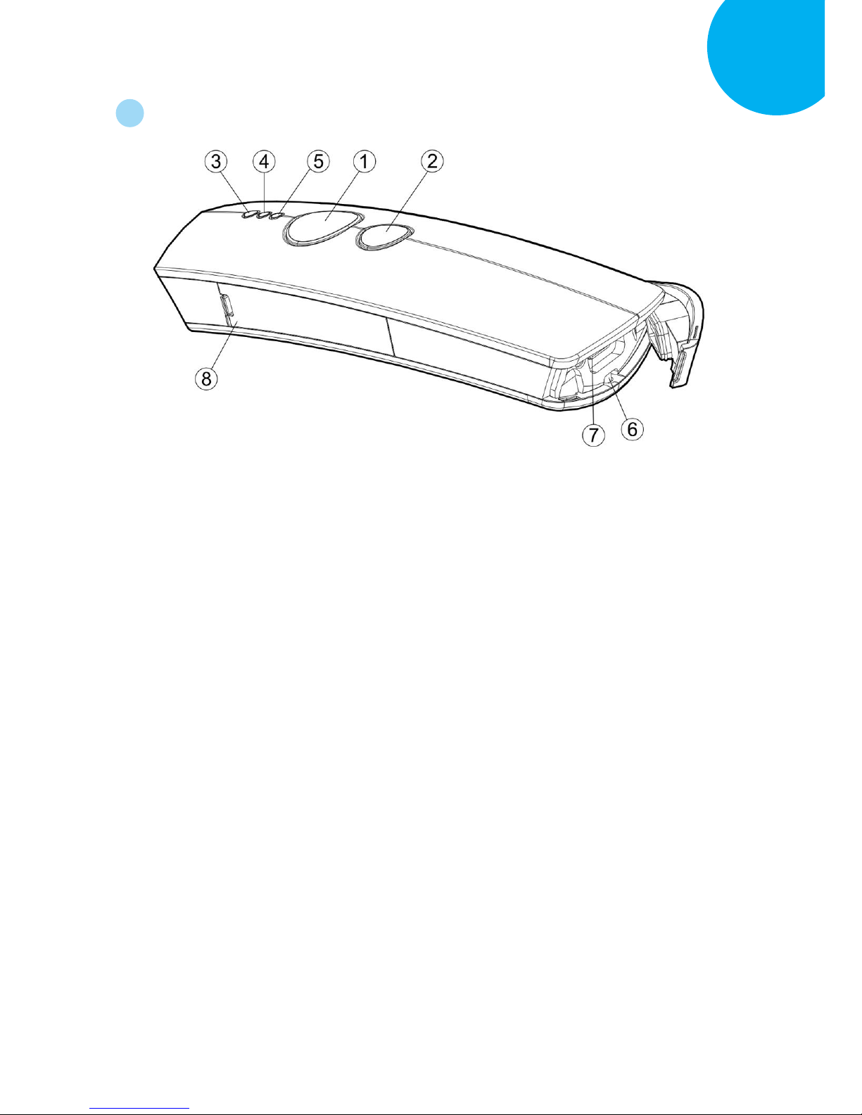
2-5. Product Overview
○
1
Press down Scan Button to decode or store the barcode.
○
2
Press down Small Trigger to perform versatile supplementary functions. For instance,
pressing the key will lead to erasing barcode data which have been previously decoded in
Memory Mode; it also works to pair the scanner with the Bluetooth devices in Bluetooth
Mode.
○
3
Good Read Indicator indicates whether the barcode is successfully decoded. Green LED
shows a successful decoding attempt.
○
4
Mode Indicator indicates the current operation mode. Blue LED stands for Bluetooth
mode, green LED for Cable mode, and orange LED for Memory mode.
○
5
Power Indicator indicates the charge status. When the battery is running low, red LED
light will be on to show a poor charge level. Once the charging process is completed, red
LED will flash slowly to show a full battery charge.
○
6
Strap Hole
○
7
Secure the interface cable into USB Host in an attempt to transmit data or to charge the
battery.
○
8
Replace the battery in the Battery Compartment.
Page 25

Enter 10 End
*/$%ENTR* *ZEND*
Introduction
2-6. Manual Layout
Chapter 1 Important Notices enumerates the list of rules and regulations which CM2D-600
conforms to as a qualified product.
Chapter 2 Introduction provides Product Specification, Product Information, Product
Overview, and Manual /Page Layout.
Chapter 3 Knowing your Scanner introduces Configuration Flowchart, LED/Beeper
Indication, and some basic operations with trigger buttons.
Chapter 4 Quick Start provides quick references to have you familiar with CM-2D600
within a short time frame.
Chapter 5 Establish a Bluetooth Connection provides instructions on how to pair
CM-2D600 with different sorts of Bluetooth devices.
Chapter 6 Editing General Setting provides related setup barcodes for configuring general
settings.
Chapter 7 Setting up your Operation Modes provides related setup barcodes for
configuring three operation modes.
Chapter 8 Configuring Symbology provides related setup barcodes for symbology
configurations.
Appendix A provides Decimal/Hexadecimal Table and ASCII Code Table for setting up
special setup barcodes.
Appendix B provides sample barcodes which you can use for testing.
Page 26
Enter 11 End
*/$%ENTR* *ZEND*
Introduction
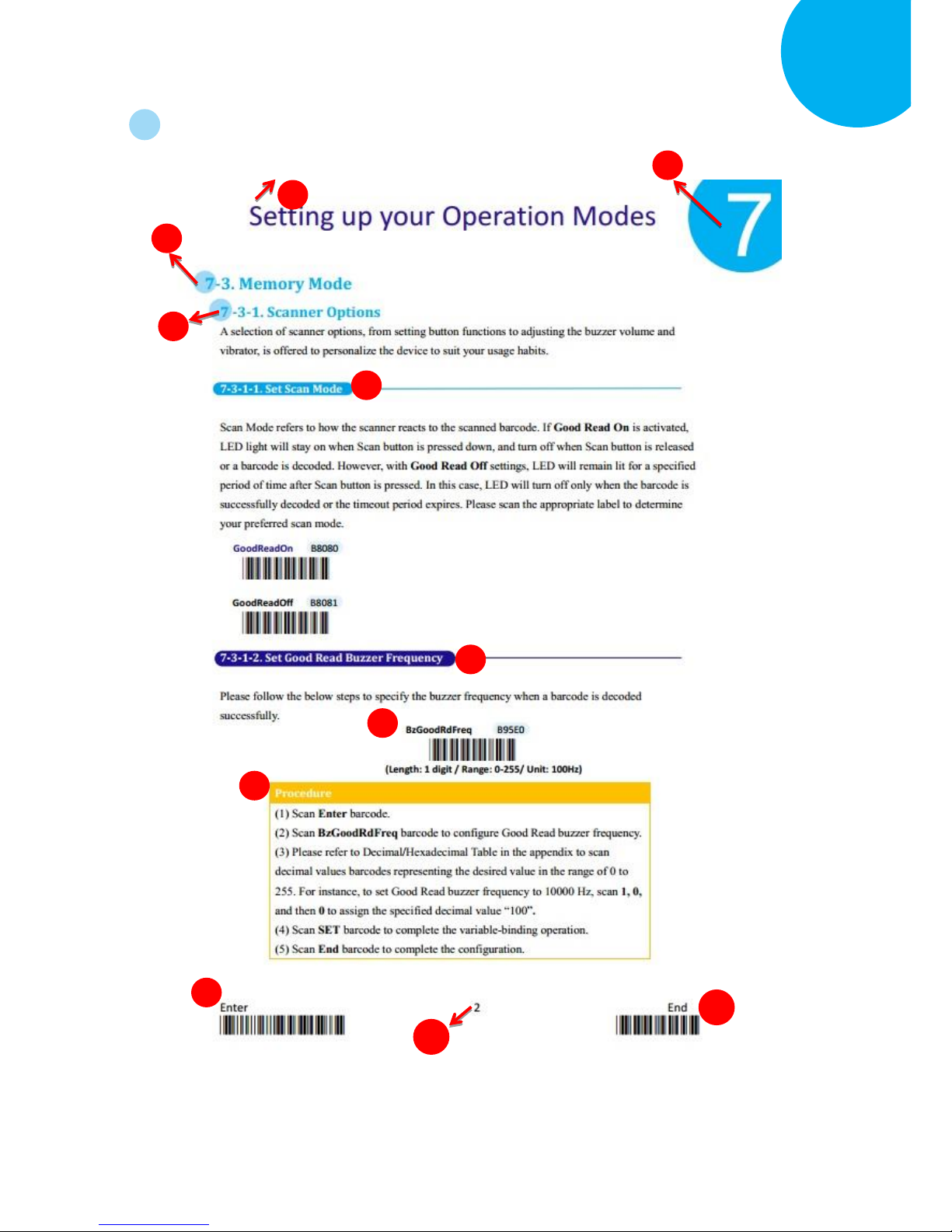
2-7. Page Layout
8 1 2 3 4 5 6
7
9
10
11
Chapter Title
Chapter Number
Section Title
Subsection Title
Page Number
Page 27
Enter 12 End
*/$%ENTR* *ZEND*
Introduction
Function Title framed with the oval shape in deep sky blue generally gives the brief description
regarding the relevant functions. However, it might also work to define regular setup barcodes which
are scattered from Chapter 6 to Chapter 8. Configuring this type of barcode normally requires simply
one-time scan to either turn on/off its functionality or to specify a predefined value, which is rather
straightforward.
Function Title framed with the oval shape in dark blue is to define special setup barcodes.
Configuring special setup barcodes usually demands more than one scan to complete relevant
configuration.
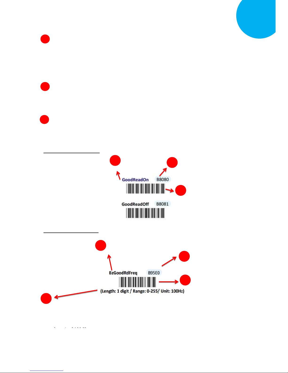
Based on Code-39, the list of setup barcodes throughout the manual will be structured as shown in
below figures:
For regular setup barcodes
For special setup barcodes
7-1
7-2
Barcode Data
Barcode Name
7-3
The concept of Reference Range aims to help you efficiently configure the setup barcode
with the suggested value in the range. In the example, you are advised that the value is
supposed to be one digit in length, to fall on the range from 0 to 255and will be measured in
7-4
Encoded Barcode Data
7-1
7-2
7-3
Encoded Barcode Data
Barcode Data
Barcode Name: the default
will be marked in the dark
blue color.
7
5
6
Page 28

Enter 13 End
*/$%ENTR* *ZEND*
Introduction
In following Configuration Steps, you will get the clear idea of how to set up these special
barcodes.
Enter label, arranged in the bottom of every page, is one of the frequently-used barcodes when it
comes to conducting your barcode-scanning activities. To ensure a valid configuration, please be
advised that you always read ENTER barcode first before proceeding with other setup barcodes.
Like Enter label, End barcode is labeled as another frequently-used barcode. It is mandatory to scan
End barcode at the end to validate your configuration. You can easily locate it at the bottom of every
page.
10
9
8
Page 29

Enter 14 End
*/$%ENTR* *ZEND*
Knowing your scanner
3
3. Knowing your Scanner
Through this informational chapter you will be exposed to a variety of helpful knowledge regarding
CM-2D600, from LED/beeper indications to the functionality of button triggers, before you start
with the scanner. Not only will it assist you in correctly and efficiently using CM-2D600 but also
help to use your time and efforts more wisely. It is encouraged to go back to this chapter for a quick
reference whenever you encounter difficulties in operating the machine.
Page 30
Enter 15 End
*/$%ENTR* *ZEND*
Knowing your scanner
3
3-1. Configuration Flowchart
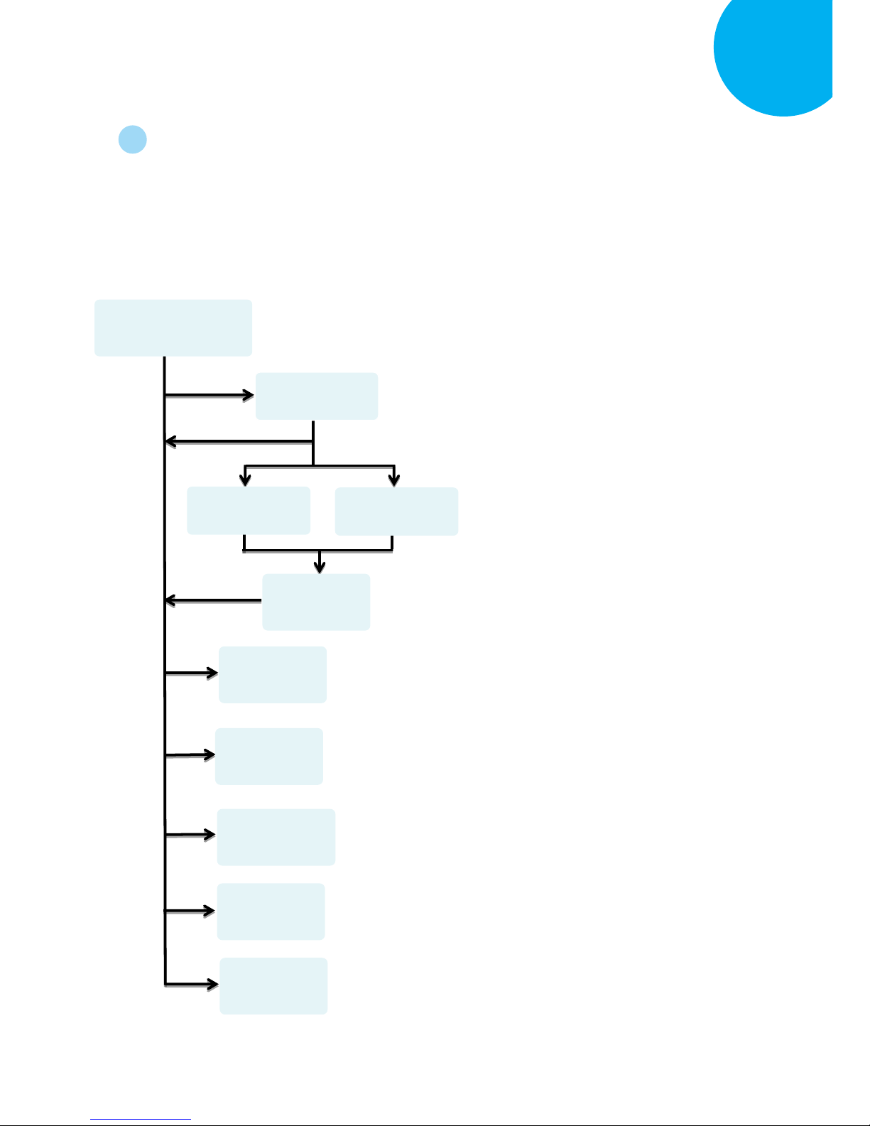
The below figure illustrates the sequences of scan events leading up to a positive scan result.
The improper operation will not only waste your efforts but also likely produce the
disappointing result which might be mistakenly viewed as a product defect. Please be
advised to refer to the flowchart whenever you attempt a scan.
Read ENTER label to enter Configuration mode.
Read Version label to retrieve Firmware information.
Read END label to exit Configuration mode.
You need to go through this process only when the
setup barcode you select to scan requires additional
configurations involving variable-binding activities. To
complete the configuration for special setup barcodes,
please refer to Decimal/Hexadecimal Table to scan
relevant value barcodes. Afterwards, you are required
to read Set label to validate your configuration.
Read Abort label to terminate the current configuration session and
exit Configuration mode.
Read ISP label to attempt a firmware update.
Select the setup barcode out of barcode pools to scan.
Read All Default label to restore your scanner back to the default
and then exit Configuration mode.
ENTER barcode
END barcode
SET barcode
ISP barcode
VERSION barcode
ALL Default barcode
ABORT barcode
Setup barcodes
Decimal barcodes
Hexadecimal
barcodes
Page 31

Enter 16 End
*/$%ENTR* *ZEND*
Knowing your scanner
3
3-2. LED & Beeper indications
LED and Beeper signals both serve to deliver visual or acoustic messages regarding the
status of the ongoing operation. Either color changes or sound pitches and melodies will
suffice to indicate a scan result as advance notification. Please refer to the below chart to use
LED and Beeper indications for your benefit while working on the device.
Functions
Beeper Sequence
LED indication
Power on the scanner
Successfully decode a barcode
Green LED flashes once
Successfully scan a regular
setup barcode
high-low tone
Successfully scan a special
setup barcode
High-low-high-low notes
Successfully enter
configuration mode
A set of five ascending notes
Red, green, and then blue
LEDs keep flashing slowly and
alternatively
Successfully enter firmware
update process
After One high tone emit five
quick short notes followed by a
pause and then two notes.
Red and green LEDs keep
flashing slowly and
alternatively
Complete scanner
configuration
A melody from high notes to
low ones
Switch to data-transmission
mode
One high note followed by two
low short notes
The orange LED keeps
flashing rapidly.
Successful attempt to transmit
all the data
One long beeping note sings
first, and then a short note
sounds after data is
transmitted.
Charging Attempt
A solid red LED indicates the
ongoing charge process. Once
the charging is completed, the
red LED will start flashing
slowly as a full battery charge
indication.
Unknown Failure
Red LED flashes once as a
warning.
Timeout for configuration
mode
Two ascending notes and then
three descending notes
Page 32

Enter 17 End
*/$%ENTR* *ZEND*
Knowing your scanner
3
Functions
Beeper Sequence
LED indication
Cable Mode
Switch to Cable mode
A melody composed of three
ascending notes, another two
ascending notes and one
comparatively high note
Green LED keeps flashing
steadily
Turn off automatic charge
Two descending short notes
Turn on automatic charge
Three high-pitched notes
Memory Mode
Switch to Memory mode
Three ascending notes
followed by a comparatively
high note
Orange LED keeps flashing
steadily
Successful attempt to erase all
saved barcodes
Three high-pitched long
sounds
Successfully attempt to delete
one single data
One note followed by two
shorter sounds.
Bluetooth Mode
Switch to Bluetooth mode
Three same low notes followed
by one high note
Blue LED keeps flashing
steadily
Successful Bluetooth pairing
Two consecutive notes
A solid Blue LED will indicate
a successful attempt.
Terminate Bluetooth
connection
Three descending notes
Unsuccessful Bluetooth pairing
Three high-pitched beeping
sounds
3-3. Leverage your Scanner with Button Triggers
Two supplementary button triggers, Scan Button and Small Trigger, are to provide
fundamental functionality from reading a barcode to deleting a scanned record, but, more
importantly, giving them a press sometimes enables you to save the efforts in conducting
complex barcode-scanning practices. Although button triggers, due to their limits, would
never suffice to cover all the major and minor tasks which setup barcodes always do,
skillfully using these two buttons still serves the basic needs yet in a more convenient way.
In the following section will demonstrate how to execute specific operations via either a
push of single button or a trigger of the button combination.
Page 33

Enter 18 End
*/$%ENTR* *ZEND*
Knowing your scanner
3
3-3.1. Scan Action
To decode a barcode, you may simply give a gentle push of Scan Button to achieve the
attempt.
3-3.2. Mode Switch
Please follow blew steps to switch among operation modes.
Procedure
(1) Hold Scan Button till LED light turns a solid color.
(2) Release Scan Button.
(3) The color of steadily flashing LED individually indicates the current
operation mode: green stands for Cable mode, orange for Memory
mode, and blue for Bluetooth mode.
3-3.3. Turn on/off Charge
Please follow the below steps to turn on or off the automatic charge.
Procedure
(1) Switch to Cable mode.
(2) Hold Small Trigger to trigger off a rapidly blinking green LED light.
(3) While LED light is rapidly flashing, press down Scan Button without
releasing Small Trigger.
(4) Release both Scan Button and Small Trigger.
3-3.4. Deletion of One Single Data
Please follow the below steps to delete a specified barcode.
Procedure
(1) Switch to Memeory Mode.
(2) Push Small trigger while aiming your scanner at the barcode you want
to delete.
(3) Release Small Trigger.
Page 34

Enter 19 End
*/$%ENTR* *ZEND*
Knowing your scanner
3
3-3.5. Deletion of All Transmitted Data
Please follow the below steps to delete all the saved barcode.
Procedure
(1) Switch to Memory mode.
(2) Hold Small Trigger to trigger off a rapidly blinking orange LED light.
(3) While LED light is rapidly flashing, press down Scan Button without
releasing Small Trigger.
(4) Release both Scan Button and Small Trigger.
3-3.6. Transmission of Saved Barcode
Please follow the below steps to transmit the saved barcode in the memory.
Procedure
(1) Hold Small Trigger till LED light turns solid color.
(2) Release Small Trigger to enter data transmission mode. The rapidly
blinking orange LED indicates the scanner is ready for data transmission.
(3) Press down Scan Button to transmit all the saved barcode data.
3-3.7. Pairing with Bluetooth Devices
Please follow the below steps to pair the scanner with other Bluetooth devices.
Procedure
(1) Switch to Bluetooth mode.
(2) Hold Small Trigger to trigger off a rapidly blinking LED light.
(3) While LED light is rapidly flashing, press down Scan Button without
releasing Small Trigger.
(4) Release both Scan Button and Small Trigger.
Page 35

Enter 20 End
*/$%ENTR* *ZEND*
Quick Start
4. Quick Start
Through straightforward instructions provided in this chapter, you will shortly familize with
fudamental operations of the scanner, and further know how to exloit the device in your tasks,
instead of painstakingly researching into the whole manul. This how-to guide will focus more on
general topics than specific or advanced subjects. If you are looking for the latter, please refer to
other chapters for some detailed explanation.
Page 36

Enter 21 End
*/$%ENTR* *ZEND*
Quick Start
4-1. Configuration Flowchart
Please make sure you always start a scan sequence with ENTER barcode and end with END
barcode as a successful attempt. Both labels can also be located on the bottom of each page.
4-2. Set up your Scanner
4-2-1. Operation Mode
We offer a selection of mode combinations, including 2in1 and 3in1 functions, for your
convenience to improve efficiency at work. Before reading the below barcodes, please scan
Enter label first to ensure a successful configuration.
Desired
barcodes
ENTER barcode
END barcode
Cable
A40C0
Bluetooth
A40C3
Cable+BT
A40C4
Cable+Mem+BT
A40C6
Memory
A40C1
Cable+Mem
A40C2
Mem+BT
A40C5
Page 37

Enter 22 End
*/$%ENTR* *ZEND*
Quick Start
4-2-2. Output Interface in Cable Mode
After scanning Enter barcode, specify which output interface the device works with in Cable
mode.
4-3. Basic Scanner Operations
You can perform most of below basic operations by either scanning the barcode sequences or
using the button triggers.
4-3-1. Mode Switch
Button Trigger
Keep holding Scan Button till the LED light turns from a rapidly blinking color into a solid
color. After a release of Scan Button, you, by observing the LED light colors, can learn
which operation mode your scanner is switched to.
Scan Sequence
After reading ENTER label, scan the below appropriate barcode to switch to the desired
operation mode.
To Cable Mode
ZTOS
To BT Mode
ZTOB
To Mem Mode
ZTOM
USB COM
B21D2
USB HID
B21D1
Page 38

Enter 23 End
*/$%ENTR* *ZEND*
Quick Start
4-3-2. Transmit All Barcode Data
Button Trigger
1. Secure the interface cable to both the barcode reader and the Host PC Open the preferred
word processing software to receive the scanned data.
2. After holding Small Trigger long enough to trigger off a solid LED light, release Small
Trigger.
3. While the orange LED starts flashing rapidly, press Scan Button once again to transmit all
barcode data.
Scan Sequence
Scan Data Memory Tx barcode after reading Enter label.
4-3-3. Clear All Saved Barcode Data
Button Trigger
1. Configure the scanner to be in Memory mode.
2. While holding Small Trigger till orange LED starts blinking rapidly, press down Scan
Button.
3. Release Scan Button and Small Trigger.
Scan Sequence
First read Enter label, and then scan the following barcode:
4-3-4. Clear One Single Barcode Data
Button Trigger
1. Configure the scanner to be in Memory mode.
2. Press down Small Trigger and scan the barcode you want to remove from the flash
memory.
Data Memory Clear
Data Memory Tx
ZMTX
Page 39

Enter 24 End
*/$%ENTR* *ZEND*
Quick Start
4-3-5. Auto-Delete All Transmitted Data
You may program the scanner by scanning Enable label to auto delete the barcode data that
was just transmitted after reading Enter barcode.
4-3-6. Attempt Firmware Update
Please read Enter label first, and then scan ISP barcode before applying relative scanner
firmware updates.
4-4. How to Make your Scanner Work with Bluetooth Dongle A-302
4-4-1. Pair with Bluetooth Dongle A-302
1. Make sure the Bluetooth dongle is well secured into the USB port of the Host PC.
2. Scan ENTER barcode.
3. Scan To BT Mode barcode to enter Bluetooth mode.
4. Press down either Scan Button or Small Trigger to establish Bluetooth connection. A
solid Blue LED indicates a successful attempt.
5. Open the referred word processing software to receive the scanned barcode data.
To BT Mode
ZTOB
ISP
ZISP
Enable
B87A1
Disable
B87A0
Page 40

Enter 25 End
*/$%ENTR* *ZEND*
Quick Start
4-4-2. Disable Pairing Function
Once a Bluetooth connection is established, Disable the pairing function, after scanning
Enter barcode, to avoid the incident of mistakenly repeating the pairing process.
4-4-3. Type of Bluetooth Connection
The type of Bluetooth connection varies according to the Bluetooth device you attempt to
pair the scanner with. Whenever you need to establish a Bluetooth connection, specify this
information out of six alternatives provided.
Pair
BE281
Disable
BE280
SPP Slave
BE1D1
iOS
BE1D4
A303
BE1D5
SPP Master
BE1D2
HID
BE1D3
A302
BE1D6
Page 41

Enter 26 End
*/$%ENTR* *ZEND*
Establish a Bluetooth Connection
5
5. Establish a Bluetooth Connection
CM-2D600 features handy scanner operations via Bluetooth technoglogy by offering great
flexibility in the Bluetooth connection types, which enables you to connect your scanner with
assorted wilreless Bluetooth devices. This chapter is thus to provide explanatory instructions on
how to establish a Bluetooth connection between CM-2D600 with other Bluetooth devices.
Page 42

Enter 27 End
*/$%ENTR* *ZEND*
Establish a Bluetooth Connection
5
5-1. Bluetooth Connection Reference Chart
Before you gear up for a Bluetooth connection, it is significant to figure out the type of
wireless Bluetooth devices which the scanner is connected with since the associated
procedures considerably vary with the device types. The below reference chart, as a
precaution, shows the relation between available connection modes and their individual
potential users to ensure a good start for a successful Bluetooth connection.
Connection Mode
Potential Users
Slave
Those who intend to connect the scanner with third-party or built-in
dongles and receive data via a terminal application
For Slave connection mode, the scanner remains inactive and waits
for connection request.
Master
Those who intend to connect the scanner with third-party or built-in
dongles and receive data via a terminal application
For Master connection mode, the scanner will take an active role in
the pairing process, meaning it will actively search for available
Bluetooth devices to establish a Bluetooth connection.
HID
Those who intend to connect the scanner with third-party or built-in
dongles and receive data via the available word-processing
applications, such Microsoft word, Notepad and so on.
iOS
Those who intend to receive data via iOS products, such as iPhone
and iPad.
A-303 Dongle
Those who intend to establish a connection with Bluetooth dongle
A-303.
A-302 Dongle
Those who intend to establish a connection with Bluetooth dongle
A-302.
Page 43
Enter 28 End
*/$%ENTR* *ZEND*
Establish a Bluetooth Connection
5
5-2. Set up your Own Bluetooth Connection
As far as configurations of Bluetooth connection are concerned, this section aims to
exemplify how you are able to establish a Bluetooth connection between CM-2D600
and Bluetooth devices in hands via step-by-step instructions.
5-2-1. Slave Connection Mode
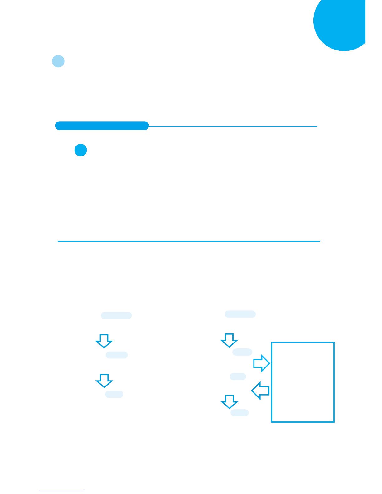
Step 1
Configure the scanner either using the utility program or scanning programming barcodes
programming. By means of the utility program provided, you need not worry about the
incorrect barcode sequence which possibly leads to the unexpected and wrong result. However,
another alternative, scanning programming barcodes, is still offered if you pursue a more
efficient configuration of the device. In case that you would rather not take time to figure out
how to exploit the utility program, directly scanning the sequence of programming barcodes
will work for you.
Scanning Programming Barcodes
1-1. Configure Output Interface of the
scanner to be Slave by scanning the
sequence of barcodes as the below
illustration shows.
1-2. Configure Mac Address information to be
the specified value “000000000000” by
scanning the sequence of barcodes as the
below illustration shows.
ENTER
/$%ENTR
Slave
BE1D1
END
ZEND
ENTER
/$%ENTR
BtMacAddr
AE8FE
Scan the sequence of
barcodes
corresponding to
“000000000000”
from
Decimal/Hexadecimal
table in Appendix A.
SET
%OK
END
ZEND
Page 44
Enter 29 End
*/$%ENTR* *ZEND*
Establish a Bluetooth Connection
5
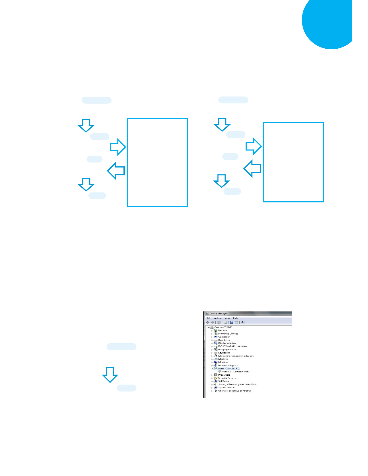
1-3. Configure Pin Code by scanning the
sequence of barcodes as the below
illustration shows.
1-4. Configure Device Name by scanning the
sequence of barcodes as the below
illustration shows.
Using Utility Program
1-1. Please have your scanner connected to
Host PC using USB cable.
1-2. To create a virtual COM port for the utility
to access your scanner, Read Enter label
> scan ISP barcode. The scanner will emit
one long sound and six short, rapid sounds
followed by two short, slow sounds as a
successful attempt.
1-3. Go to Control Panel> Device Manager.
The created virtual COM port would be
found in Ports (COM & LPT) group. In
the example, COM4 is used as the virtual
COM port.
ENTER
/$%ENTR
ISP
ZISP
ENTER
/$%ENTR
BtPinCode
AE0E9
Scan the sequence of
barcodes
corresponding to the
desired pin code, scan
the sequence of
barcodes from
Decimal/Hexadecimal
table in Appendix A.
SET
%OK
END
ZEND
ENTER
/$%ENTR
BtDevName
AF4E6
SET
%OK
Scan the sequence of
barcodes
corresponding to the
desired Device Name
from
Decimal/Hexadecimal
table in Appendix A.
END
ZEND
Page 45
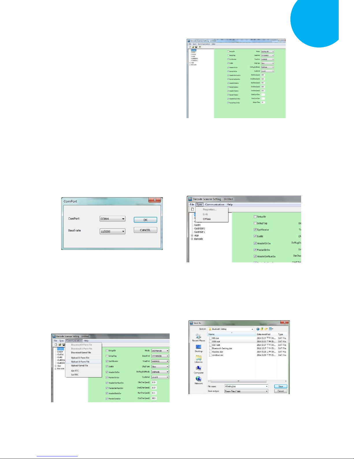
Enter 30 End
*/$%ENTR* *ZEND*
Establish a Bluetooth Connection
5
1-4. Invoke the utility program located in
Product CD.
1-5. Select Sync> Property. In ComPort
pop-up dialogue box, configure ComPort
properly according to the virtual COM
port created in Step 3 and leave Baud rate
with its default. In the example, configure
it with COM4.
1-6. Select Sync> Link to link the scanner
with the utility program. Once the link is
successfully established, Link/Property
options in Sync menu will be greyed out
and the status bar will show associated
information.
1-7. Before configuring your scanner, you need
to upload the scanner status first to ensure
the current setting will not be overwritten.
In doing so, Select Communication>
Upload U-Parm File.
1-8. As a Save as dialogue box pops up,
specify the file name and click Save
button.
Page 46
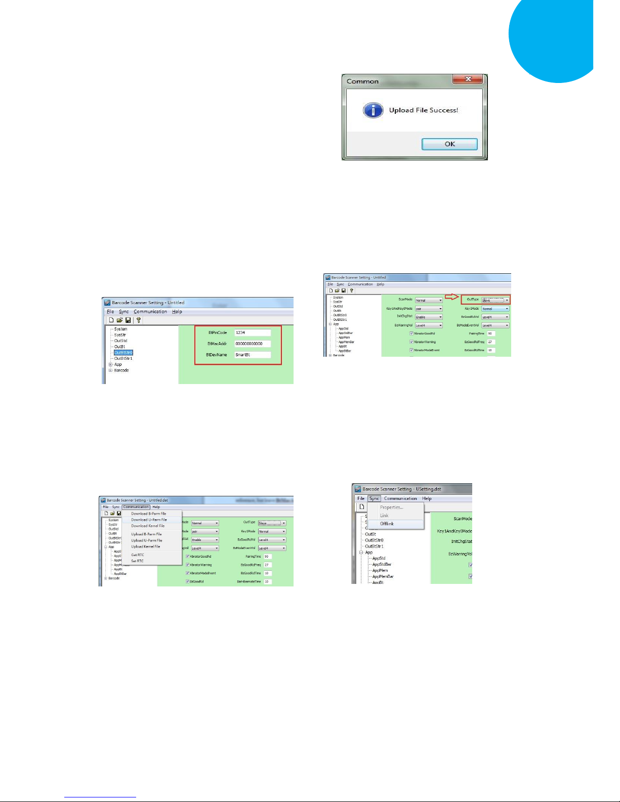
Enter 31 End
*/$%ENTR* *ZEND*
Establish a Bluetooth Connection
5
1-9. After the upload process is done, a
message box will appear to indicate
whether the operation is done successfully.
1-10. Click on OutBtStr0 item of the tree
view in the left panel. Afterwards,
Configure BtPinCode and BtDevName
according to your reference, but leave
BtMacAddr with the default value,
000000000000
1-11. In the tree view, select App>AppBt. In
the right panel, Select Slave in the
OutType combo box. Then, click Save
icon on the toolbar to save your
settings.
1-12. Select Communication>Download
U-Parm file to apply the cutomized
settings to the scanner.
1-13. Select Sync> Offlink to complete the
configuration.
Page 47
Enter 32 End
*/$%ENTR* *ZEND*
Establish a Bluetooth Connection
5
Step 2
Pair the scanner with third-party Bluetooth dongle.
2-1. Please have your scanner switch to Bluetooth mode. Choose one of two alternatives listed
below to help you achieve the attempt.
When the current mode indicator does not flash blue, please hold Scan Button long enough to
have LED light turn a solid color. Then, after a release of Scan Button, you can tell which
operation mode it switches to by observing LED color. Repeat the steps printed in bold if
blue LED does not blink after releasing the Scan Button.
Scan the below barcode.
2-2. Pair your scanner with third-party Bluetooth dongle by either of two options suggested below.
After holding small trigger till blue LED starts blinking rapidly, press down Scan Button
without releasing Small Trigger. Then releasing Scan button and Small trigger at the same time
will initiate the pairing process.
Scan the below barcode.
To BT Mode
ZTOB
BT Pairing
ZPAR
IMPORTANT: Please properly perform Step 2-1 and 2-2 to ensure the dongle is able to detect
the scanner at any time. While following the below steps to proceed with the configuration,
please make sure that scanner always stays in Bluetooth mode and awaits a Bluetooth connection
by an indication of a steadily flashing blue light. If the scanner is being put into sleep, press down
either Scan Button or Small Trigger once to wake up the scanner.
ENTER
/$%ENTR
ENTER
/$%ENTR
Page 48
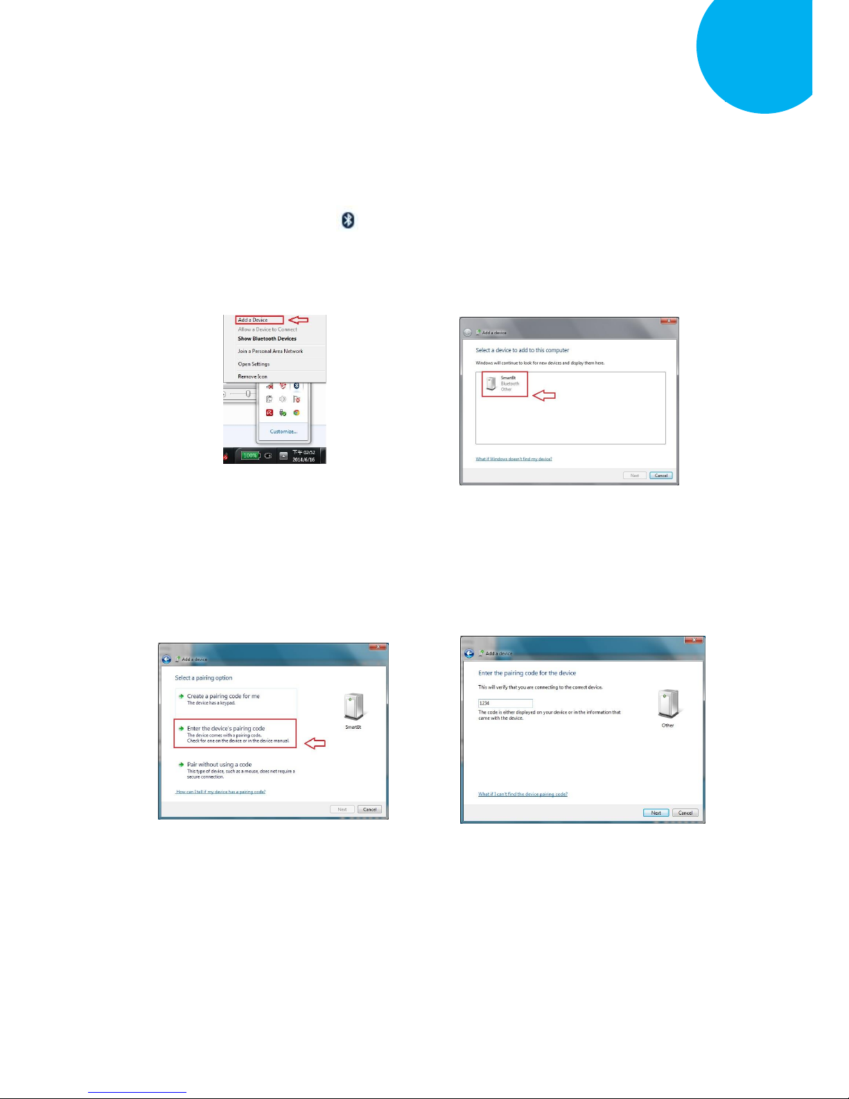
Enter 33 End
*/$%ENTR* *ZEND*
Establish a Bluetooth Connection
5
2-3. Secure third-party dongle into Host PC
and confirm the scanner stays active in
Bluetooth mode.
2-4. Right-click on Bluetooth icon on the
taskbar and select Add a Device in the
pop-up submenu.
2-5. In the list box of Add a Device dialogue
box will display all the available
Bluetooth devices after a search. Select
the device with the name which you
specify for the scanner while using the
utility application to program it. In this
example, click on SmartBt item. Then,
hit Next button.
2-6. Select Enter the device’s pairing code
and then hit Next button.
2-7. For verification, enter the valid passcode
in Passcode field. In this example, input
the passcode, 1234.
Page 49
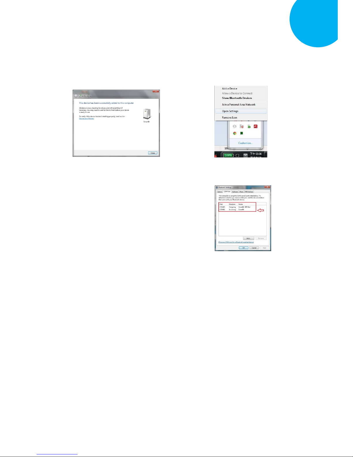
Enter 34 End
*/$%ENTR* *ZEND*
Establish a Bluetooth Connection
5
2-8. A message will appear to indicate the
dongle and the scanner have been paired
successfully. Press down Close button to
close Add a device dialogue box.
2-9. Right-click on Bluetooth icon on the
taskbar and then select Open Settings to
look up the created outgoing COM port
info.
2-10. In the Bluetooth Setting dialogue box,
click on COM ports tab. From the list
box of COM Ports tab, you are able to
retrieve the outgoing COM ports
information. Close dialogue box by
hitting OK button. In this example, the
outgoing COM port is set to COM15.
Page 50
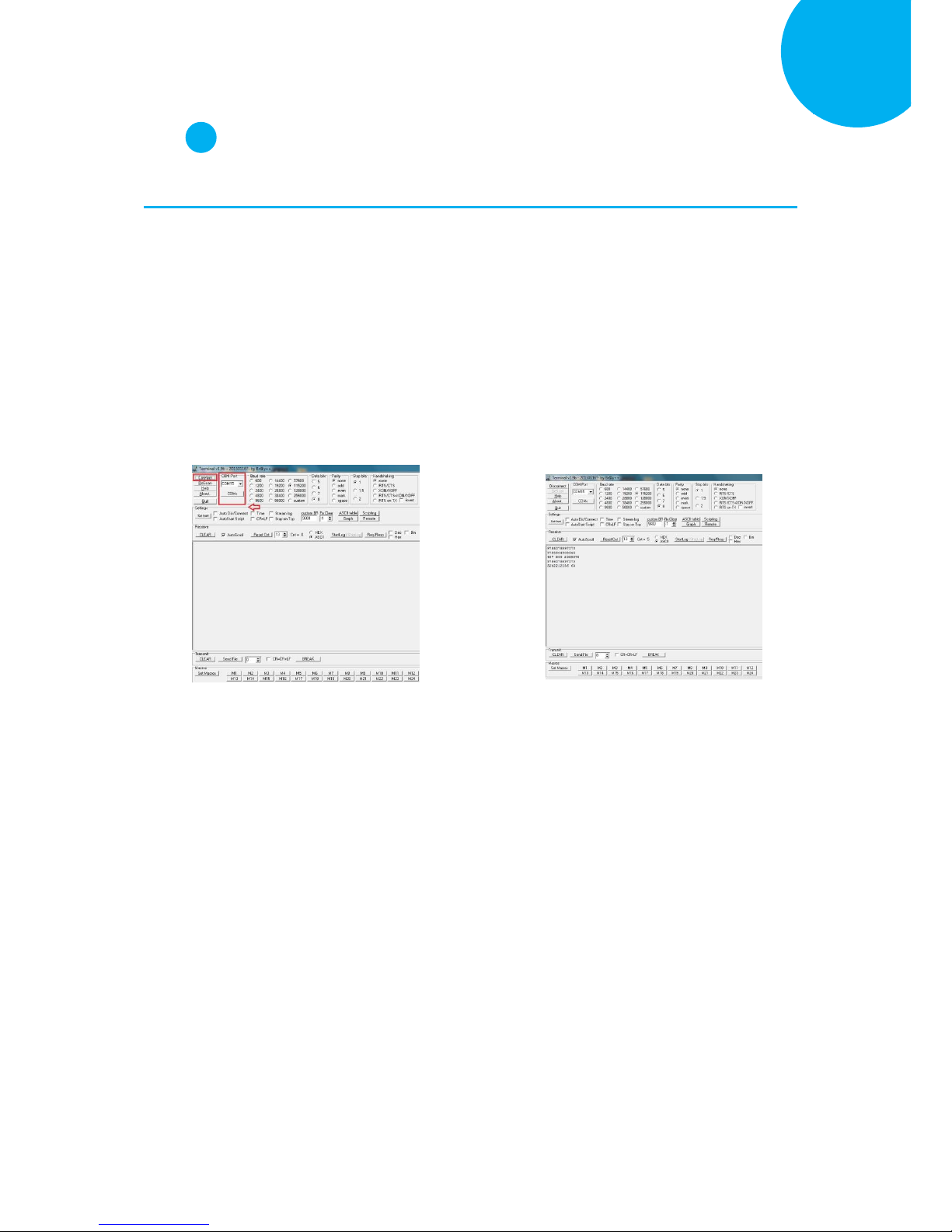
Enter 35 End
*/$%ENTR* *ZEND*
Establish a Bluetooth Connection
5
Step 3
Configure the terminal software.
3-1. Launch the existing terminal emulation program. We will demonstrate the case with a free
terminal emulation application, Terminal.
3-2. Properly set COM Port value according
to information you obtain in Step 2-10,
and then hit Connect button to ensure the
termial application is connected. In this
example, select COM15 from the combo
box.
3-3. After a few seconds, the scanner will
emit a short, rapid note along with a solid
blue LED to indicate a successful
Bluetooth connection. Now, you are able
to receive barcode data via terminal
software.
Page 51
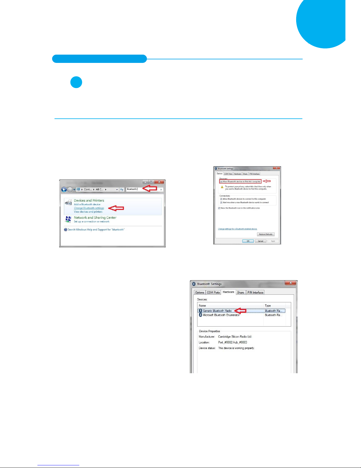
Enter 36 End
*/$%ENTR* *ZEND*
Establish a Bluetooth Connection
5
5-2-2. Master Connection Mode
Step 1
Configure Bluetooth settings, look up for the MAC address of your Bluetooth dongle, and
create an incoming port.
1-1. Secure third-party Bluetooth dongle into Host PC.
1-2. In Control Panel, type Bluetooth in
search box. In the list of search results,
click on Change Bluetooth Settings
item.
1-3. In Bluetooth Settings, click on Options
tab to check Allow Bluetooth devices to
find this computer option.
1-4. Switching to Hardware tab in the
Bluetooth Settings, d-click on Generic
Bluetooth Radio item in the Device list
box.
Page 52
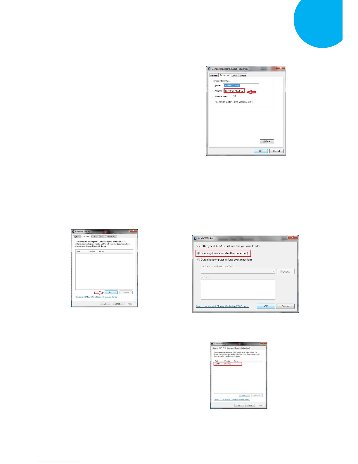
Enter 37 End
*/$%ENTR* *ZEND*
Establish a Bluetooth Connection
5
1-5. In Generic Bluetooth Radio Properties,
retrieve MAC address of the plugged-in
Bluetooth dongle, which is illustrated in
the below figure and marked with red
frame. Please write down the info for
configuring your scanner later on. In this
example, Mac address info is
00116778E81C. Click OK button to return
to Bluetooth Settings.
1-6. Click on COM Ports tab to add an
incoming port. In COM Ports tab, hit
Add button to invoke Add COM Port
dialogue box.
1-7. In Add COM Port dialogue box, select
Incoming (device initiates the
connection) option and then hit OK
button to initiate the process.
1-8. Once the incoming port is successfully
generated, the list box in COM Ports tab
will show associated information
regarding the incoming port. In the
example, the created incoming port is set
to COM14. Press down OK button to
close Bluetooth Settings dialogue box.
Page 53
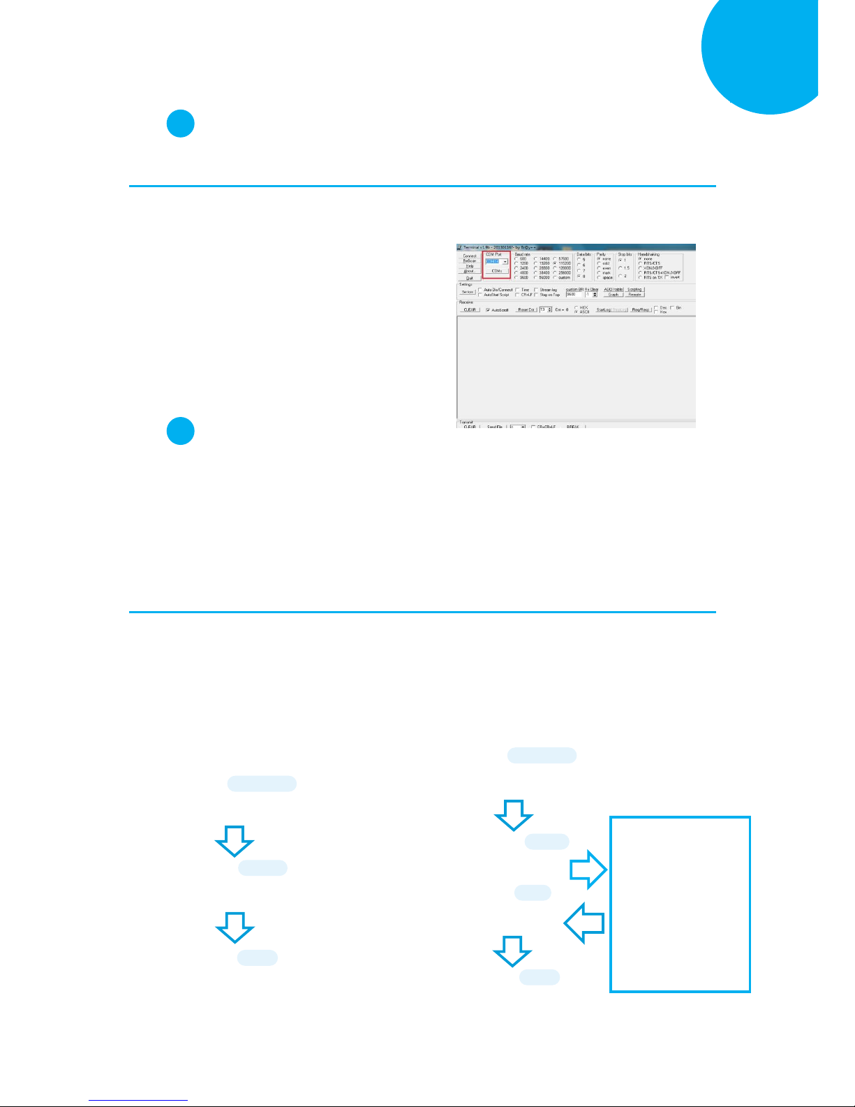
Enter 38 End
*/$%ENTR* *ZEND*
Establish a Bluetooth Connection
5
Step 2
Configure the existing terminal application.
2-1. Run the terminal software. In the example, we will demonstrate the case with the free terminal
emulation application, Terminal.
2-2. Correctly configure COM Port with the
value matching the generated incoming
COM port, and then press down Connect
button to ensure the terminal application
is connected. Keep the application
running in the background.
Step 3
Configure your scanner either using the utility program or scanning programming barcodes.
Two alternatives take different approaches to serve the same purpose. Select utility program to
set up the device if you incline to avoid from dealing with lengthy and problematic barcode
sequences which constantly end up nullifying your efforts. For those who prefer a
straightforward solution, it is suggested to scan the sequence of programming barcodes to
have your device programmed before use.
Scanning Program Barcodes
3-1. Configure Output Interface of the
scanner to be Master by scanning the
sequence of barcodes as the below
illustration shows.
3-2. Configure Mac Address by scanning the
sequence of barcodes as the below
illustration shows.
ENTER
/$%ENTR
Master
BE1D2
END
ZEND
ENTER
/$%ENTR
BtMacAddr
AE8FE
Scan the sequence of
barcodes
corresponding to the
actual MAC address
of the dongle from
Decimal/Hexadecimal
table in Appendix A.
SET
%OK
END
ZEND
Page 54
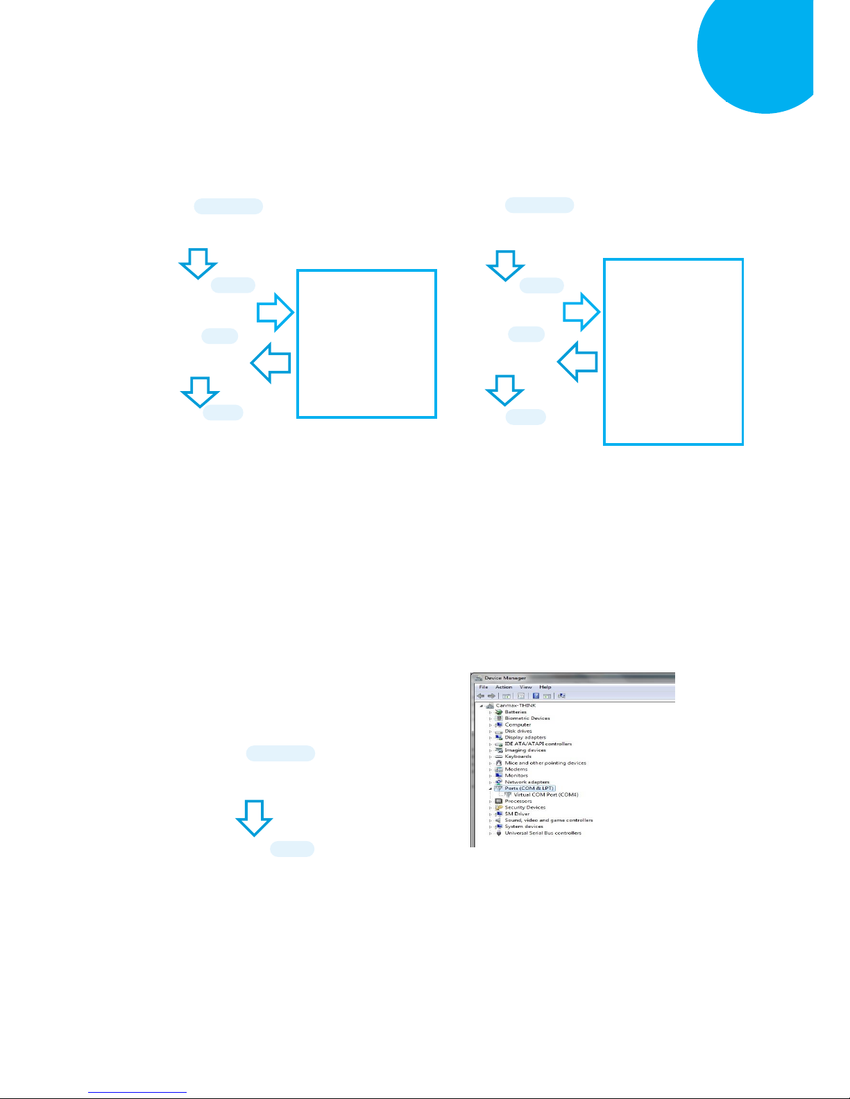
Enter 39 End
*/$%ENTR* *ZEND*
Establish a Bluetooth Connection
5
3-3. Configure Pin Code by scanning the
sequence of barcodes as the below
illustration shows.
3-4. Configure Device Name by scanning the
sequence of barcodes as the below
illustration shows.
Using Utility Program
3-1. Please have your scanner connected to
Host PC using USB cable.
3-2. To create a virtual COM port for the
utility to access your scanner, Read
Enter label > scan ISP barcode. The
scanner will emit one long sound and six
short, rapid sounds followed by two short,
slow sounds as a successful attempt.
3-3. Go to Control Panel > Device
Manager. The created virtual COM port
would be found in Ports (COM & LPT)
group. In the example, COM4 is used as
the virtual COM port.
ENTER
/$%ENTR
ISP
ZISP
ENTER
/$%ENTR
BtPinCode
AE0E9
SET
%OK
Scan the sequence of
barcodes
corresponding to the
desired pin code from
Decimal/Hexadecimal
table in Appendix A.
END
ZEND
ENTER
/$%ENTR
BtDevName
AF4E6
SET
%OK
Scan the sequence of
barcodes
corresponding to the
desired Device Name
from
Decimal/Hexadecimal
table in Appendix A.
END
ZEND
Page 55
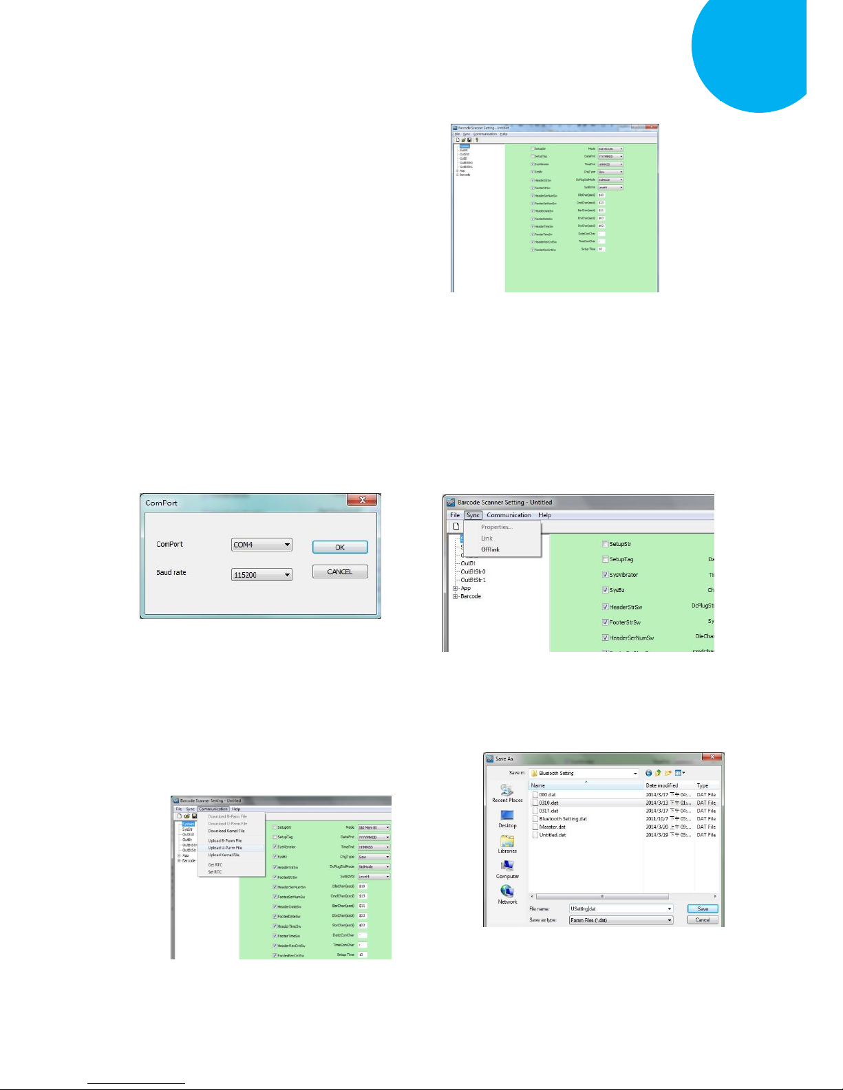
Enter 40 End
*/$%ENTR* *ZEND*
Establish a Bluetooth Connection
5
3-4. Invoke the utility program located in
Product CD.
3-5. Select Sync> Property. In ComPort
pop-up dialogue box, configure
ComPort properly according to the
virtual COM port created in Step 3 and
leave Baud rate with its default. In the
example, configure it with COM4.
3-6. Select Sync>Link to link the scanner
with the utility program. Once the link is
successfully established, Link/Property
options in Sync menu will be greyed out
and the status bar will show associated
information.
3-7. Before configuring your scanner, you
need to upload the scanner status first to
ensure the current setting will not be
overwritten. In doing so, Select
Communication> Upload U-Parm File.
3-8. As a Save as dialogue box pops up,
specify the file name and click Save
button.
Page 56
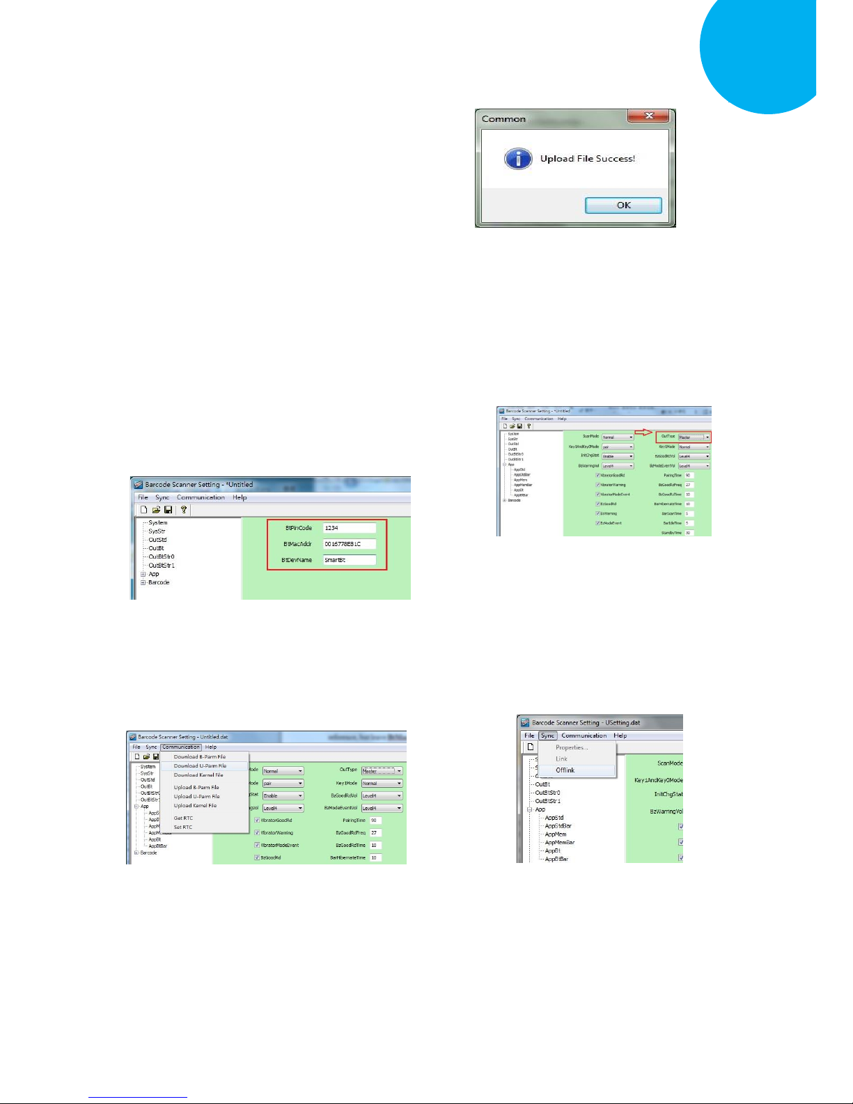
Enter 41 End
*/$%ENTR* *ZEND*
Establish a Bluetooth Connection
5
3-9. After the upload process is done, a
message box will appear to indicate
whether the operation is done
successfully.
3-10. Click on OutBtStr0 item of the tree
view in the left panel. Afterwards,
Configure BtPinCode and BtDevName
according to your reference, but
associate BtMacAddr with MAC
address information of the Bluetooth
device which you look up in the
computer.
3-11. In the tree view, select App>AppBt. In
the right panel, select Master in the
OutType combo box. Then, click Save
icon on the toolbar to save your
settings.
3-12. Select Communication>Download
U-Parm file to apply the customized
settings to the scanner
.
3-13. Select Sync> Offlink to complete the
configuration.
Page 57
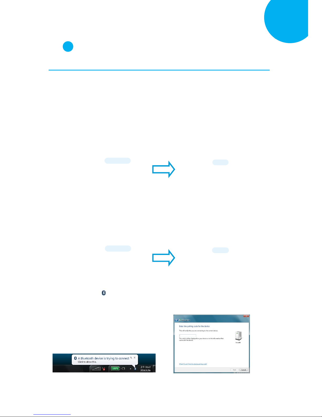
Enter 42 End
*/$%ENTR* *ZEND*
Establish a Bluetooth Connection
5
Step 4
Initiate the process to pair the scanner with third-party Bluetooth dongle.
4-1. Please switch to Bluetooth mode. Choose one of two alternatives listed below to help you
achieve the attempt.
When the current mode indicator does not flash blue, please hold Scan Button long enough to
have LED light turn a solid color. Then, after a release of Scan Button, you can tell which
operation mode it switches to by observing LED color. Repeat the steps printed in bold if
blue LED does not blink after releasing the Scan Button.
Scan the below barcode.
4-2. Pair your scanner with third-party Bluetooth dongle by either of two options suggested below.
After holding small trigger till blue LED starts blinking rapidly, press down Scan Button
without releasing Small Trigger. Then releasing Scan button and Small trigger at the same time
will initiate the pairing process.
Scan the below barcode.
4-3. When Bluetooth device is detected,
Bluetooth icon will appear on the
taskbar with a pop-up message saying “a
Bluetooth device is trying to connect”.
You have to timely click on the message
to accordingly have Add a device
dialogue box prompted before
proceeding with the configuration.
4-4. In Add a device dialogue box, correctly
enter the pairing code in Passcode field.
Then, hit Next button to check the result.
To BT Mode
ZTOB
BT Pairing
ZPAR
ENTER
/$%ENTR
ENTER
/$%ENTR
Page 58
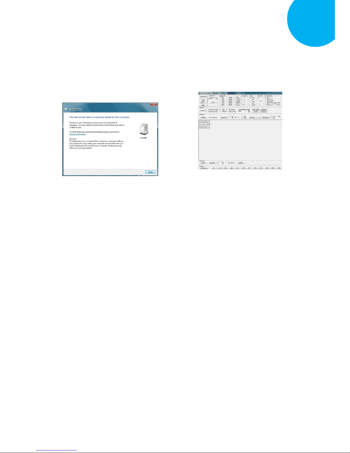
Enter 43 End
*/$%ENTR* *ZEND*
Establish a Bluetooth Connection
5
4-5. The appropriate message will pop up to
indicate a success when the valid
passcode is properly entered. If the
passcode verification fails due to the
timeout, please repeat the steps from
Step 4-2 to 4-4.
4-6.
4-6. Once Bluetooth connection is established
successfully, switch back to the terminal
application to start receiving barcode
data.
Page 59
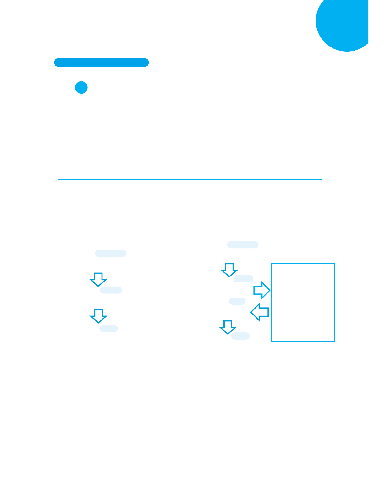
Enter 44 End
*/$%ENTR* *ZEND*
Establish a Bluetooth Connection
5
5-2-3. HID Connection Mode
Step 1
Configure your scanner either using the utility program or scanning programming barcodes.
The convenience of using utility program will save you trouble scanning the sequence of
barcode which demands great caution and high accuracy to work out the configuration.
However, you may alternatively choose to scan programming barcodes to set up your scanner
if you desire a time-saving configuration rather than a research into sophistication of utility
program before using it. Considering all pros and cons mentioned above, please choose the one
which works best for you.
Scanning Programming Barcodes
1-1. Configure Output Interface of the
scanner to be HID by scanning the
sequence of barcodes as the below
illustration shows.
1-2. Configure Device Name by scanning the
sequence of barcodes as the below
illustration shows.
ENTER
/$%ENTR
Hid
BE1D3
END
ZEND
ENTER
/$%ENTR
BtDevName
AF4E6
SET
%OK
Scan the sequence of
barcodes
corresponding to the
desired Device Name
from
Decimal/Hexadecimal
table in Appendix A.
END
ZEND
Page 60
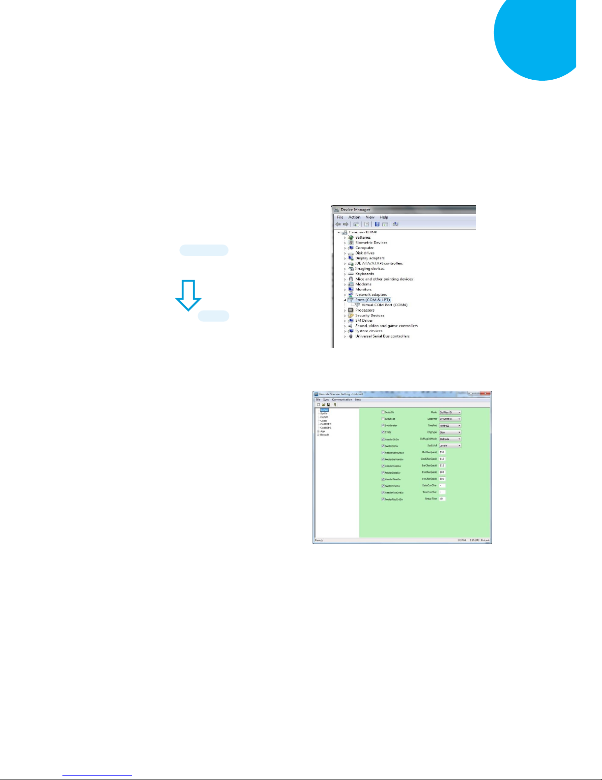
Enter 45 End
*/$%ENTR* *ZEND*
Establish a Bluetooth Connection
5
Using Utility Program
1-1. Please have your scanner connected to
Host PC using USB cable.
1-2. To create a virtual COM port for the
utility to access your scanner, Read
Enter label > scan ISP barcode. The
scanner will emit one long sound and six
short, rapid sounds followed by two short,
slow sounds as a successful attempt.
1-3. Go to Control Panel> Device Manager.
The created virtual COM port would be
found in Ports (COM & LPT) group. In
the example, COM4 is used as the virtual
COM port.
1-4. Invoke the utility program located in
Product CD.
ISP
ZISP
ENTER
/$%ENTR
Page 61
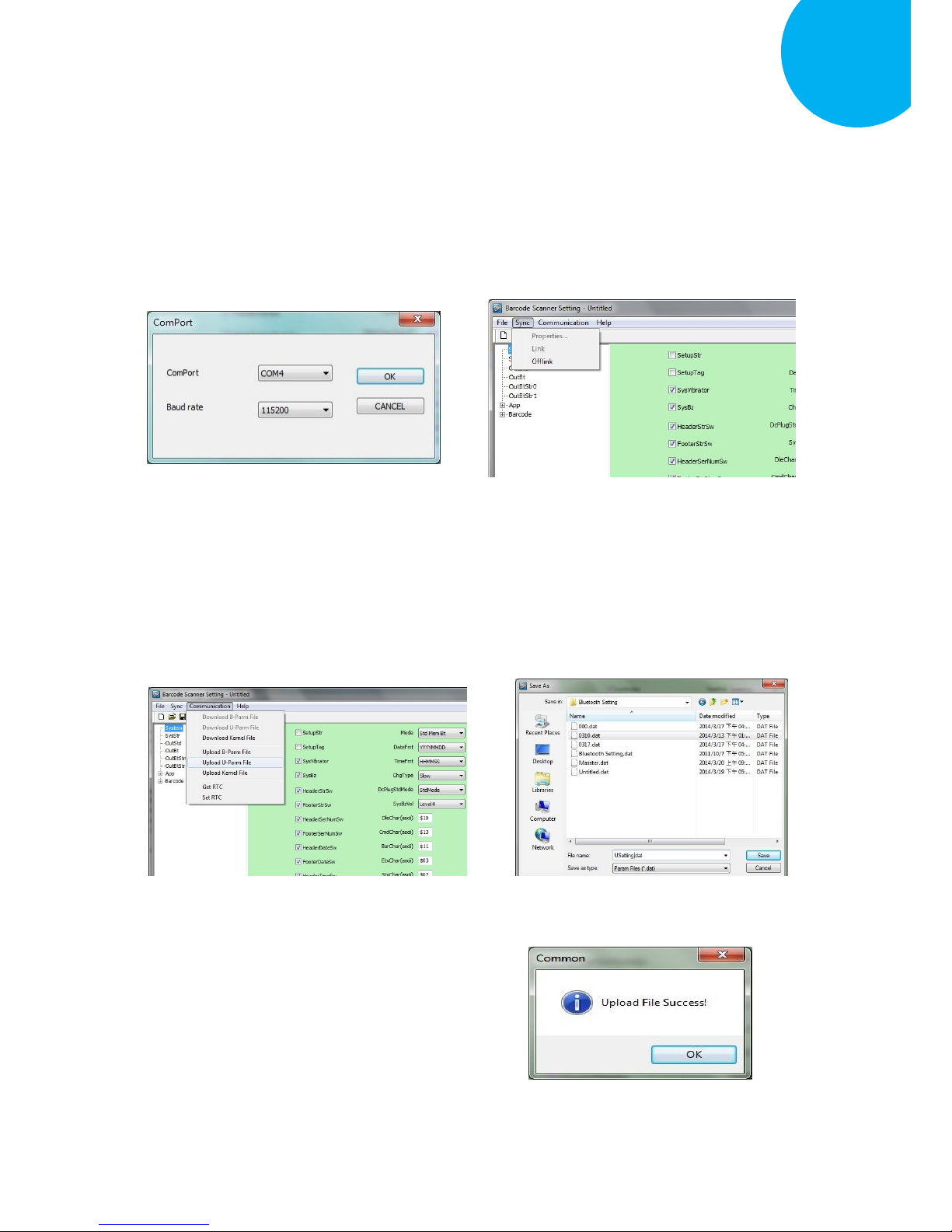
Enter 46 End
*/$%ENTR* *ZEND*
Establish a Bluetooth Connection
5
1-5. Select Sync> Property. In ComPort
pop-up dialogue box, configure ComPort
properly according to the virtual COM
port created in Step 3 and leave Baud
rate with its default. In the example,
configure it with COM4.
1-6. Select Sync> Link to link the scanner
with the utility program. Once the link is
successfully established, Link/Property
options in Sync menu will be greyed out
and the status bar will show associated
information.
1-7. Before configuring your scanner, you
need to upload the scanner status first to
ensure the current setting will not be
overwritten. In doing so, Select
Communication> Upload U-Parm File.
1-8. As a Save as dialogue box pops up,
specify the file name and click Save
button.
1-9. After the upload process is done, a
message box will appear to indicate
whether the operation is done
successfully.
Page 62
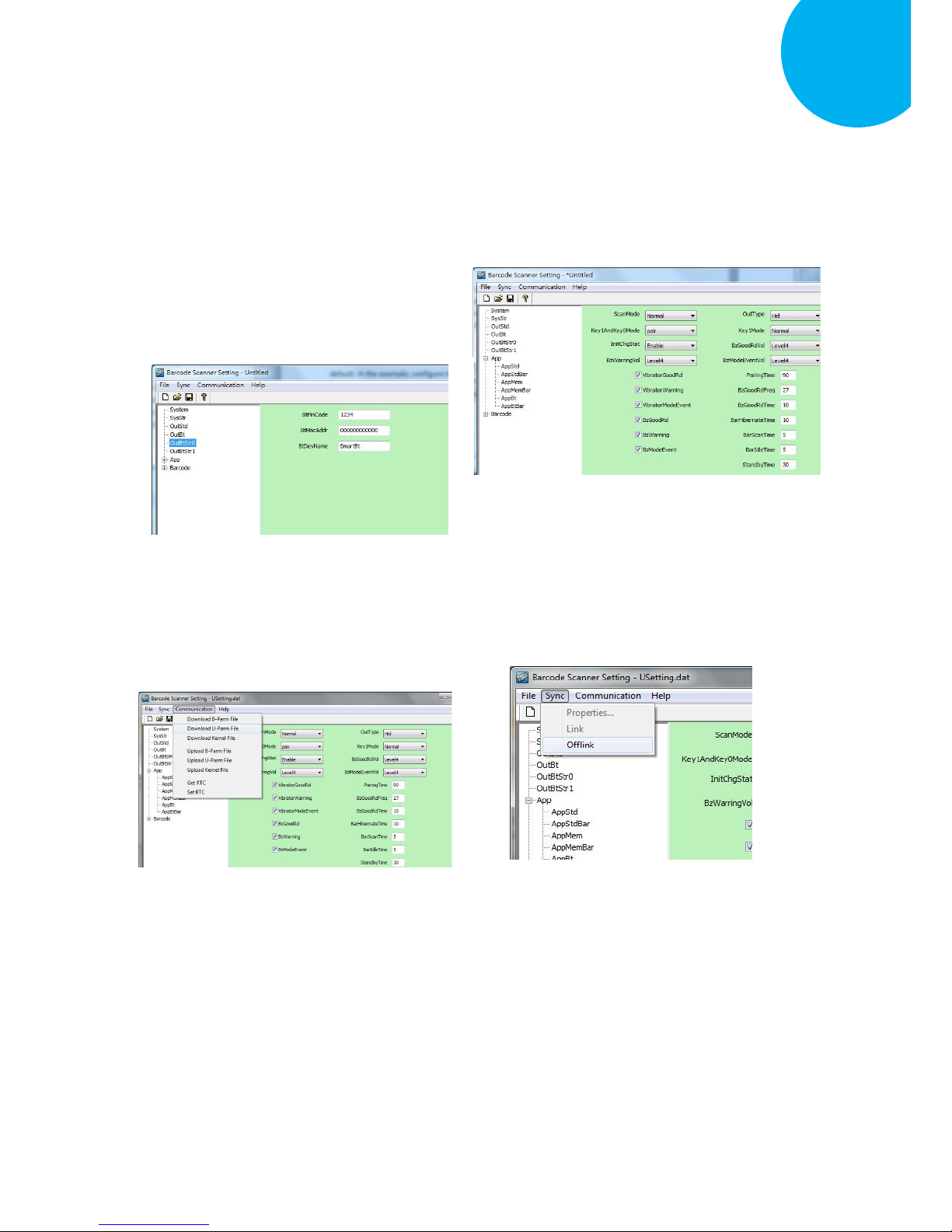
Enter 47 End
*/$%ENTR* *ZEND*
Establish a Bluetooth Connection
5
1-10. Click on OutBtStr0 item of the tree
view in the left panel. Afterwards,
Configure BtPinCode and BtDevName
according to your reference, but
associate BtMacAddr with MAC
address information of the Bluetooth
device which you look up in the
computer.
1-11. In the tree view, select App>AppBt. In
the right panel, Select HID in the
OutType combo box. Click Save icon
on the toolbar to save your settings.
1-12. Select Communication>Download
U-Parm file to apply the customized
settings to the scanner.
1-13. Select Sync> Offlink to complete the
configuration.
Page 63
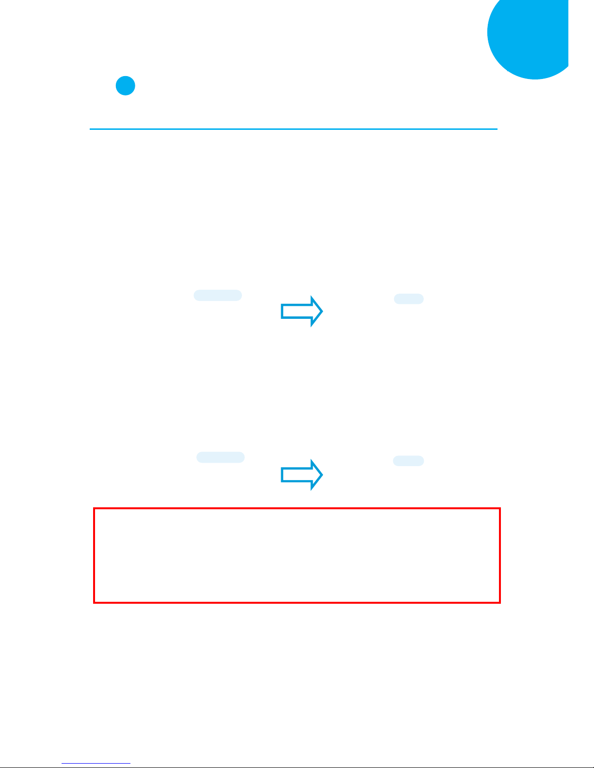
Enter 48 End
*/$%ENTR* *ZEND*
Establish a Bluetooth Connection
5
Step 2
Pair the scanner with third-party Bluetooth dongle.
2-1. Please have your scanner switch to Bluetooth mode. Choose one of two alternatives listed
below to help you achieve the attempt.
When the current mode indicator does not flash blue, please hold Scan Button long enough to
have LED light turn a solid color. Then, after a release of Scan Button, you can tell which
operation mode it switches to by observing LED color. Repeat the steps printed in bold if
blue LED does not blink after releasing the Scan Button.
Scan the below barcode.
2-2. Pair your scanner with third-party Bluetooth dongle by either of two options suggested below.
After holding small trigger till blue LED starts blinking rapidly, press down Scan Button
without releasing Small Trigger. Then releasing Scan button and Small trigger at the same time
will initiate the pairing process.
Scan the below barcode.
To BT Mode
ZTOB
BT Pairing
ZPAR
IMPORTANT: Please properly perform Step 2-1 and 2-2 to ensure the dongle is able to detect
the scanner at any time. While following the below steps to proceed with the configuration,
please make sure that scanner always stays in Bluetooth mode and awaits a Bluetooth connection
by an indication of a steadily flashing blue light. If the scanner is being put into sleep, press
down either Scan Button or Small Trigger once to wake up the scanner.
ENTER
/$%ENTR
ENTER
/$%ENTR
Page 64
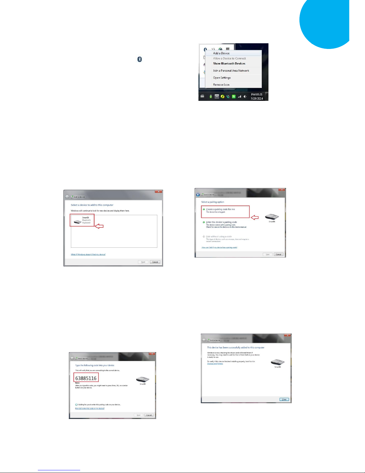
Enter 49 End
*/$%ENTR* *ZEND*
Establish a Bluetooth Connection
5
2-3. When Bluetooth device is detected,
R-click on Bluetooth icon on the task
bar, and select Add a Device in the
pop-up submenu.
2-4. In Add a Device dialogue box, the list
box will display all the available
Bluetooth devices after a search. Select
the device with the name which you
specify for the scanner. In this example,
click on SmartBt item. Then, hit Next
button.
2-5. If the similar dialogue box appears as the
below figure suggests (depending upon
Bluetooth settings in your computer, the
mentioned dialogue box may not show
up), select Create a pairing code for me
and then hit Next button. If not, skip to
next step.
2-6. Refer to Decimal/Hexadecimal table in
Appendix A to accurately scan the
sequence of barcodes which matches to
the generated code shown in the dialogue
box for pin code verification. In this
example, please scan 6,3,8,8,5,1,1, and 6.
2-7. A message will appear to indicate the
dongle and the scanner have been paired
successfully. Press down Close button to
close Add a device dialogue box.
Page 65

Enter 50 End
*/$%ENTR* *ZEND*
Establish a Bluetooth Connection
5
Step 3
Launch the existing text editing application to
receive barcode data.
Page 66
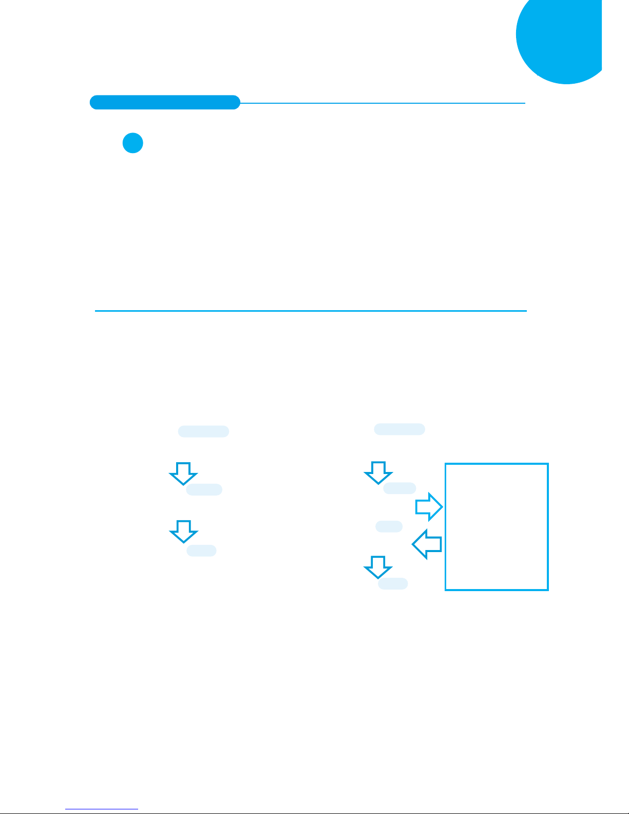
Enter 51 End
*/$%ENTR* *ZEND*
Establish a Bluetooth Connection
5
5-2-4. iOS Connection Mode
Step 1
Configure your scanner either using the utility program or scanning programming barcodes.
The primary advantage of using the utility program is to prevent the invalid configuration
which frequently happens due to the incorrect and reckless scanning sequence. However, it
requires extra pre-configuration procedures before the utility program can be executed properly.
On the other hand, the use of barcode programming sequence will lead to a rapid and efficient
configuration for your scanner instead of taking time to dig into the seemingly confusing
application. Considering all pros and cons mentioned above, choose the one which fits for your
situation.
Scanning Programming Barcodes
1-1. Configure Output Interface of the
scanner to be iOS by scanning the
sequence of barcodes as the below
illustration shows.
1-2. Configure Device Name by scanning the
sequence of barcodes as the below figure
show. By default, Device name is set to
“SmartBt.”
ENTER
/$%ENTR
iOS
BE1D4
END
ZEND
ENTER
/$%ENTR
BtDevName
AF4E6
SET
%OK
Scan the sequence of
barcodes
corresponding to the
desired Device Name
from
Decimal/Hexadecimal
table in Appendix A.
END
ZEND
Page 67
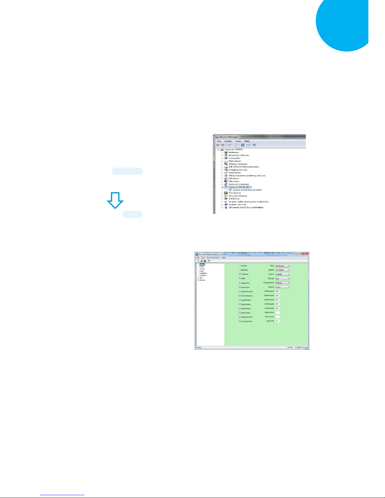
Enter 52 End
*/$%ENTR* *ZEND*
Establish a Bluetooth Connection
5
Using Utility Program
1-1. Please have your scanner connected to
Host PC using USB cable.
1-2. To create a virtual COM port for the
utility to access your scanner, Read
Enter label > scan ISP barcode. The
scanner will emit one long sound and six
short, rapid sounds followed by two short,
slow sounds as a successful attempt.
1-3. Go to Control Panel> Device Manager.
The created virtual COM port would be
found in Ports (COM & LPT) group. In
the example, COM3 is used as the virtual
COM port.
1-4. Invoke the utility program located in
Product CD.
ENTER
/$%ENTR
ISP
ZISP
Page 68
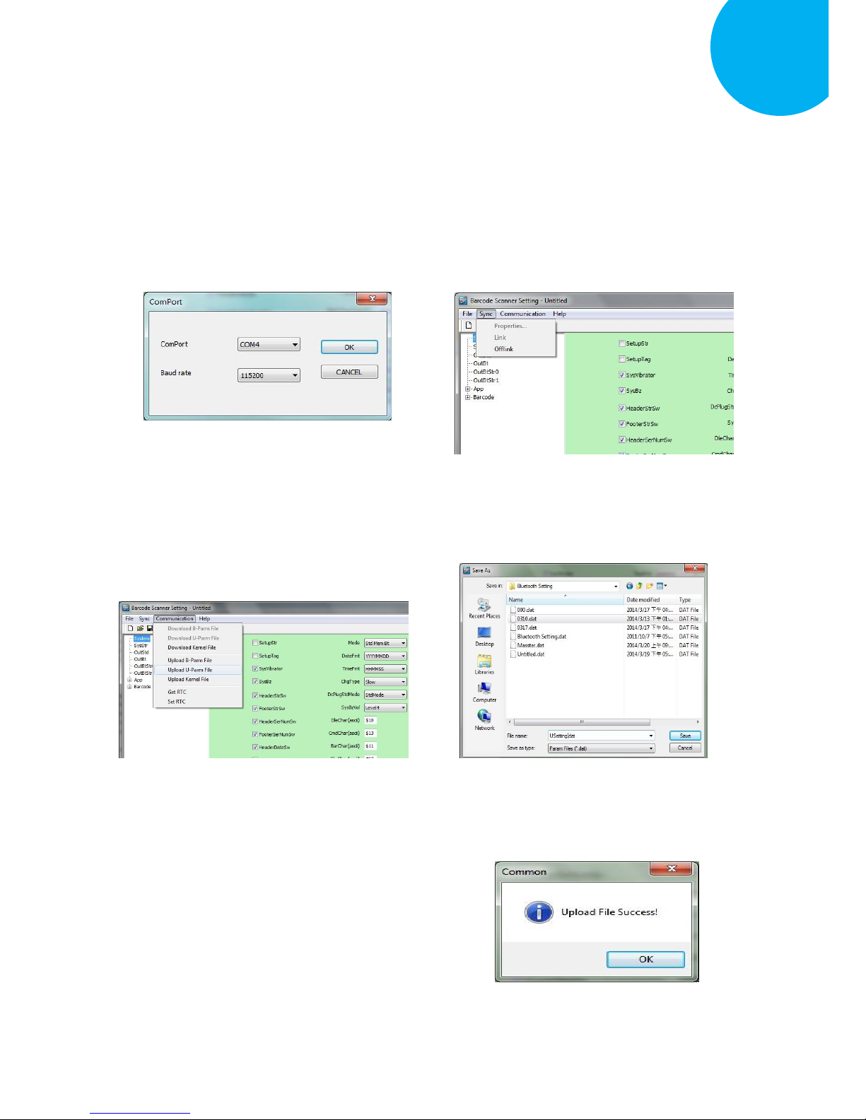
Enter 53 End
*/$%ENTR* *ZEND*
Establish a Bluetooth Connection
5
1-5. Select Sync> Property. In ComPort
pop-up dialogue box, configure
ComPort properly according to the
virtual COM port created in Step 3 and
leave Baud rate with its default. In the
example, configure it with COM4.
1-6. Select Sync>Link to link the scanner
with the utility program. Once the link is
successfully established, Link/Property
options in Sync menu will be greyed out
and the status bar will show associated
information.
1-7. Before configuring your scanner, you
need to upload the scanner status first to
ensure the current setting will not be
overwritten. In doing so, Select
Communication> Upload U-Parm File.
1-8. As a Save as dialogue box pops up,
specify the file name and click Save
button.
1-9. After the upload process is done, a
message box will appear to indicate
whether the operation is done
successfully.
Page 69
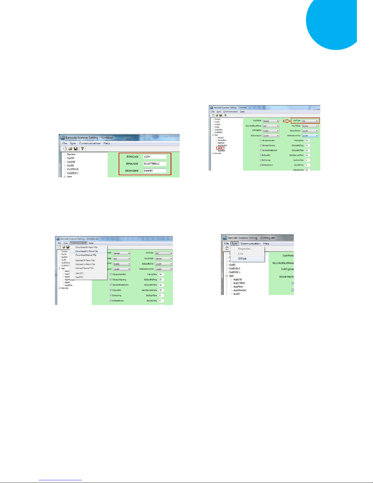
Enter 54 End
*/$%ENTR* *ZEND*
Establish a Bluetooth Connection
5
1-10. Click on OutBtStr0 item of the tree view
in the left panel. Afterwards, Configure
BtPinCode and BtDevName according
to your reference, but associate
BtMacAddr with MAC address
information of the Bluetooth device
which you look up in the computer.
1-11. In the tree view, select App>AppBt. In
the right panel, select iOS in the
OutType combo box. Then, click Save
icon on the toolbar to save your settings.
1-12. Select Communication>Download
U-Parm file to apply the customized
settings to the scanner.
1-13. Select Sync> Offlink to complete the
configuration.
Page 70
Enter 55 End
*/$%ENTR* *ZEND*
Establish a Bluetooth Connection
5
Step 2
Initiate the process to pair the scanner with third-party Bluetooth dongle.
2-1. Please switch to Bluetooth mode. Choose one of two alternatives listed below to help you
achieve the attempt.
When the current mode indicator does not flash blue, please hold Scan Button long enough to
have LED light turn a solid color. Then, after a release of Scan Button, you can tell which
operation mode it switches to by observing LED color. Repeat the steps printed in bold if
blue LED does not blink after releasing the Scan Button.
Scan the below barcode.
2-2. Pair your scanner with third-party Bluetooth dongle by either of two options suggested below.
After holding small trigger till blue LED starts blinking rapidly, press down Scan Button
without releasing Small Trigger. Then releasing Scan button and Small trigger at the same time
will initiate the pairing process.
Scan the below barcode.
To BT Mode
ZTOB
BT Pairing
ZPAR
IMPORTANT: In order to pair the scanner with iPad, please make sure that scanner always
stays in Bluetooth mode and awaits a Bluetooth connection by an indication of a steadily
flashing blue light. If the scanner is being put into sleep, press down Scan Button or Small
Trigger to wake up the scanner; or, repeat Step 2-2 when the timeout period expires.
ENTER
/$%ENTR
ENTER
/$%ENTR
Page 71
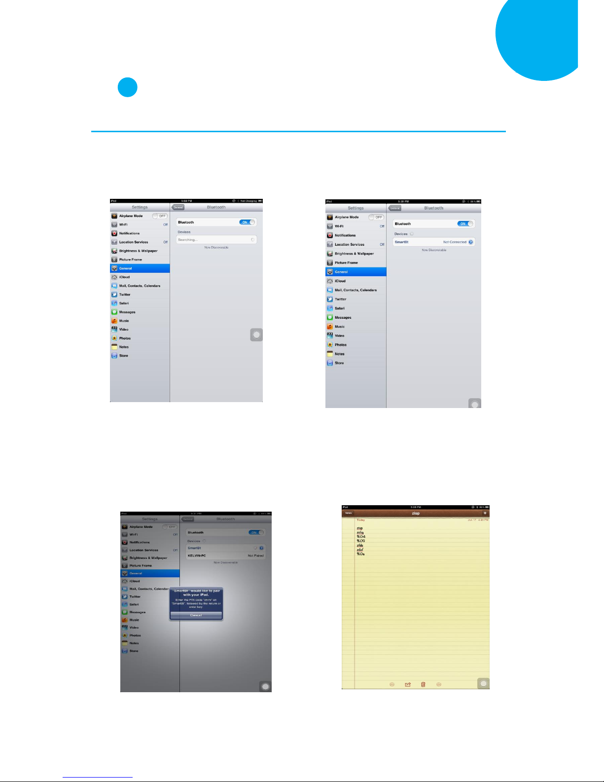
Enter 56 End
*/$%ENTR* *ZEND*
Establish a Bluetooth Connection
5
Step 3
Configure your Apple products. In this example, we will demonstrate the case with iPad.
3-1. Activate your iPad. Tap Setting, go to
General> Bluetooth, and then turn on
Bluetooth settings.
3-2. From the list of available Bluetooth
devices in range, Click on the device
which you intend to pair iPad with.
3-3. According to pop-up message, correctly
scan the passcode for verification. In this
example, please read the sequence of
decimal barcodes, 3-5-7-9. Repeat this
step till it succeeds.
3-4. Once iPad successfully pairs with the
scanner, press Home button to return to
Home page. Then, tap Notes to receive
barcode data.
Page 72
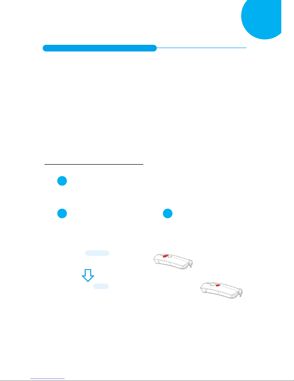
Enter 57 End
*/$%ENTR* *ZEND*
Establish a Bluetooth Connection
5
5-2-5. Bluetooth Dongle A303 Connection Mode
Bluetooth Dongle A303 is a specialized Bluetooth peripheral device adapted for use of
CM-2D600 via HID or SPP interface in attempt to leverage Bluetooth technology. An
optional purchase of Bluetooth dongle A303 could prevent you from going through the
complicated configuration since it is well programmed beforehand with all the necessary
Bluetooth settings before the delivery. Accordingly, performing Bluetooth operations out
of CM-2D600 for the very first time simply demands a press of button to recover the
Bluetooth connection unless the scanner is re-programmed to pair with third-party dongle
or other Bluetooth devices previously. In case that you possibly adopt a different
approach to establish a Bluetooth connection for whatever reasons, the step-by-step
instruction is still provided so that you are able to make CM-2D600 work with Bluetooth
dongle A303
.
Work with Dongle A303 for the First Time Use
Step 1
Secure the Bluetooth dongle A303 into Host PC.
Step 2
Scan the sequence of barcodes listed below to
switch the scanner to Bluetooth operation
mode.
Step 3
Press down either Scan Button or Small Trigger
to recover Bluetooth connection. A solid blue
LED indicates a successful attempt.
ENTER
/$%ENTR
To BT Mode
ZTOB
Page 73
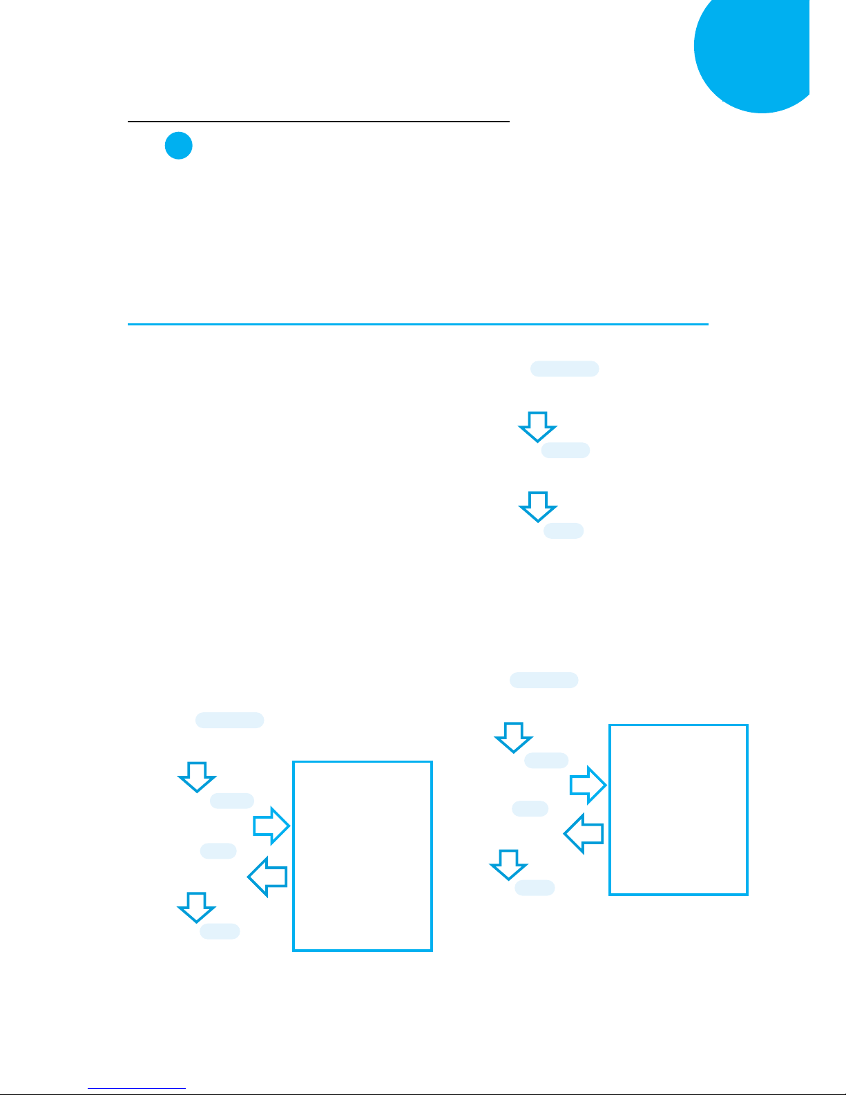
Enter 58 End
*/$%ENTR* *ZEND*
Establish a Bluetooth Connection
5
How to Re-Configure your Scanner to Work with Dongle A303
Step 1
Configure your scanner either using the utility program or scanning programming barcodes.
The approach of utility program will help you accurately program your device with no need to
go through the sequence of barcode scans which occasionally produces erroneous results due to
the lack of cares. As another alternative, scanning programming barcodes would work better
if you rather adopt a more time-saving approach than allocate time or other resources to
familiarize with the utility program.
Scanning Programming Barcodes
1-1. Configure Output Interface of the
scanner to be A303 by scanning the
sequence of barcodes as the illustration on
the right side shows.
1-2. Retrieve Mac Address info on the side of
Bluetooth dongle A303, and then
configure Mac Address by scanning the
sequence of barcodes as the below
illustration shows.
1-3. Configure Device Name by scanning the
sequence of barcodes as the below
illustration shows.
ENTER
/$%ENTR
A303
BE1D5
END
ZEND
ENTER
/$%ENTR
BtMacAddr
B08FE
Scan the sequence of
barcodes
corresponding to the
actual MAC address
of the dongle from
Decimal/Hexadecimal
table in Appendix A.
SET
%OK
END
ZEND
ENTER
/$%ENTR
BtDevName
B14E6
SET
%OK
Scan the sequence of
barcodes
corresponding to the
desired Device Name
from
Decimal/Hexadecimal
table in Appendix A.
END
ZEND
Page 74
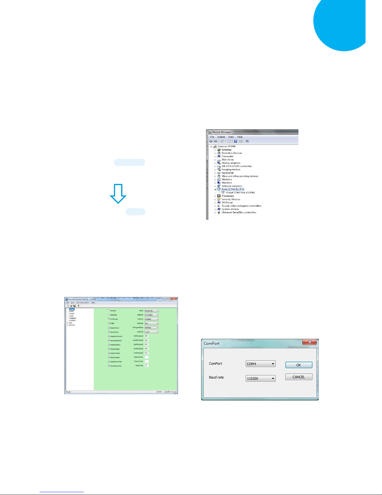
Enter 59 End
*/$%ENTR* *ZEND*
Establish a Bluetooth Connection
5
Using Utility Program
1-1. Please have your scanner connected to
Host PC using USB cable.
1-2. To create a virtual COM port for the
utility to access your scanner, Read
Enter label > scan ISP barcode. The
scanner will emit one long sound and six
short, rapid sounds followed by two short,
slow sounds as a successful attempt.
1-3. Go to Control Panel> Device Manager.
The created virtual COM port would be
found in Ports (COM & LPT) group. In
the example, COM3 is used as the virtual
COM port.
1-4. Invoke the utility program located in
Product CD.
1-5. Select Sync> Property. In ComPort
pop-up dialogue box, configure ComPort
properly according to the virtual COM
port created in Step 3 and leave Baud
rate with its default. In the example,
configure it with COM4.
ISP
ZISP
ENTER
/$%ENTR
Page 75
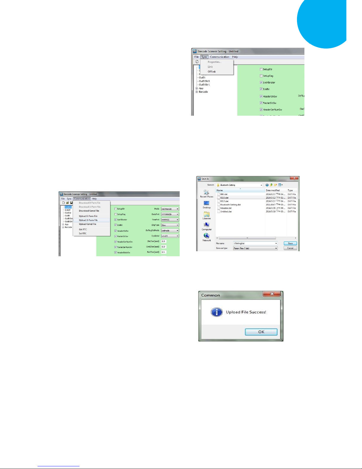
Enter 60 End
*/$%ENTR* *ZEND*
Establish a Bluetooth Connection
5
1-6. Select Sync> Link to link the scanner
with the utility program. Once the link is
successfully established, Link/Property
options in Sync menu will be greyed out
and the status bar will show associated
information.
1-7. Before configuring your scanner, you
need to upload the scanner status first to
ensure the current setting will not be
overwritten. In doing so, Select
Communication> Upload U-Parm File.
1-8. As a Save as dialogue box pops up,
specify the file name and click Save
button.
1-9. After the upload process is done, a
message box will appear to indicate
whether the operation is done
successfully.
Page 76
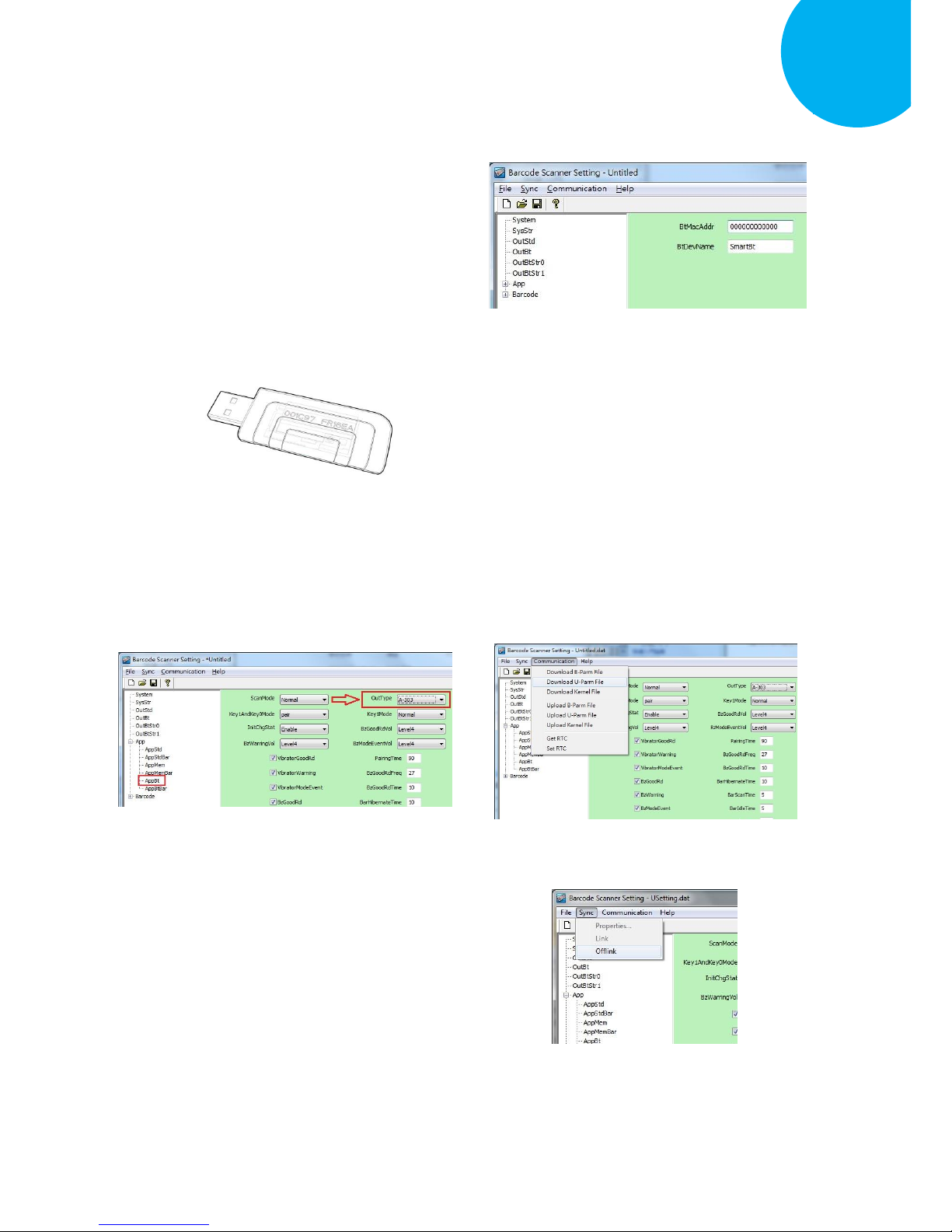
Enter 61 End
*/$%ENTR* *ZEND*
Establish a Bluetooth Connection
5
1-10. Click on OutBtStr1 item of the tree
view in the left panel. Afterwards,
Configure BtDevName according to
your reference, but associate
BtMacAddr with MAC address
information which is clearly marked on
the side of Bluetooth dongle A303. In
this example, the MAC address is
001C97FR16EA.
1-11. In the tree view, select App>AppBt. In
the right panel, select A303 in the
OutType combo box. Click Save icon
on the toolbar to save your settings.
1-12. Select Communication>Download
U-Parm file to apply the customized
settings to the scanner.
1-13. Select Sync> Offlink to complete the
configuration.
Page 77

Enter 62 End
*/$%ENTR* *ZEND*
Establish a Bluetooth Connection
5
Step 2
Pair the scanner with third-party Bluetooth dongle.
2-1. Please have your scanner switch to Bluetooth mode. Choose one of two alternatives listed
below to help you achieve the attempt.
Using Button Triggers
When the current mode indicator does not flash blue, please hold Scan Button long enough to
have LED light turn a solid color. Then, after a release of Scan Button, you can tell which
operation mode it switches to by observing LED color. Repeat the steps printed in bold if
blue LED does not blink after releasing the Scan Button.
Scanning Programming Barcodes
Scan the below barcode.
2-2. Pair your scanner with third-party Bluetooth dongle by either of two options suggested below.
Using Button Triggers
After holding small trigger till blue LED starts blinking rapidly, press down Scan Button
without releasing Small Trigger. Then releasing Scan button and Small trigger at the same time
will initiate the pairing process.
Scanning Programming Barcodes
Scan the below barcode.
To BT Mode
ZTOB
BT Pairing
ZPAR
ENTER
/$%ENTR
ENTER
/$%ENTR
Page 78

Enter 63 End
*/$%ENTR* *ZEND*
Establish a Bluetooth Connection
5
Step 3
Properly scan the sequence of barcodes to determine the output interface via which the scanner
interacts with other devices. To configure output interface, there are two interface options,
HID interface and Virtual COM interface, for you to select from.
HID Interface
3-1. Scan the below barcodes to activate HID
interface.
3-2. Launch the existing text editing software
to receive barcode data.
Virtual COM Interface
3-1. Scan the below barcodes to activate
Virtual COM interface.
3-2. Go to Control Panel> Device Manager.
The created virtual COM port would be
found in Ports (COM & LPT) group. In
the example, COM13 is used as the
virtual COM port.
Keyboard
/$%ZKBD
ENTER
/$%PROG
RS232 Default
ENTER
/$%PROG
Page 79
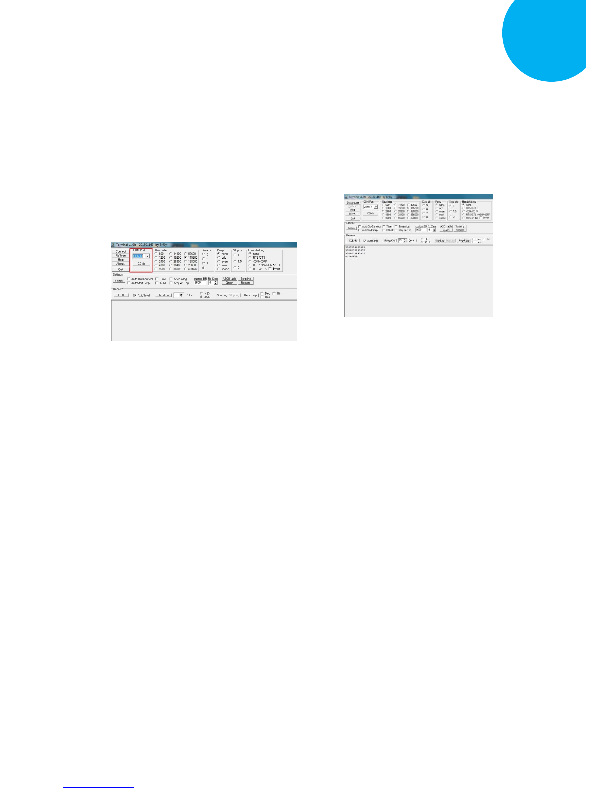
Enter 64 End
*/$%ENTR* *ZEND*
Establish a Bluetooth Connection
5
3-3. Run the terminal software. In the example, we will demonstrate the case with a free terminal
emulation application, Terminal.
3-4. Correctly configure COM Port with the
value matching the generated virtual
COM port, and then press down Connect
button to ensure the terminal application
is connected.
3-5. Now you are able to receive barcode data
via terminal software.
Page 80
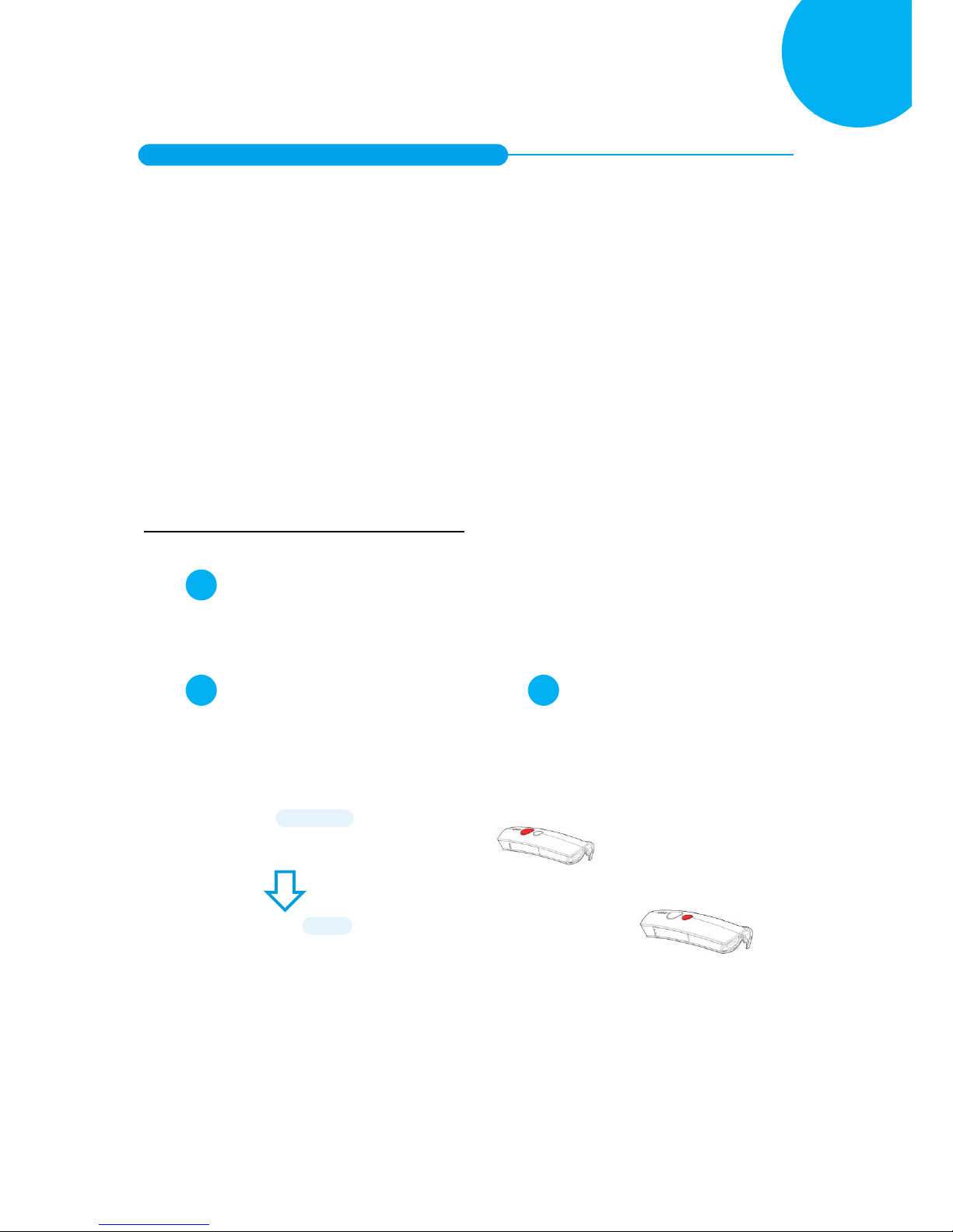
Enter 65 End
*/$%ENTR* *ZEND*
Establish a Bluetooth Connection
5
5-2-6. Bluetooth Dongle A302 Connection Mode
Bluetooth Dongle A302 is a specialized Bluetooth peripheral device adapted for use of
CM-2D600 via HID interface in attempt to leverage Bluetooth technology. An optional
purchase of Bluetooth dongle A302 could prevent you from going through the
complicated configuration since it is well programmed beforehand with all the necessary
Bluetooth settings before the delivery. Accordingly, performing Bluetooth operations out
of CM-2D600 for the very first time simply demands a press of button to recover the
Bluetooth connection which is earlier configured unless the scanner is re-programmed to
pair with third-party dongle or other Bluetooth devices. In case that you possibly adopt a
different approach to establish a Bluetooth connection for whatever reasons, the
step-by-step instruction is still provided so that you are able to make CM-2D600 work
with Bluetooth dongle A302 again.
Work with Dongle A302 for the First Time Use
Step 1
Secure the Bluetooth dongle A302 into Host PC.
Step 2
Scan the sequence of barcodes listed below to
switch the scanner to Bluetooth operation
mode.
Step 3
Press down either Scan Button or Small Trigger
to recover Bluetooth connection. A solid blue
LED indicates a successful attempt.
ENTER
/$%ENTR
To BT Mode
ZTOB
Page 81
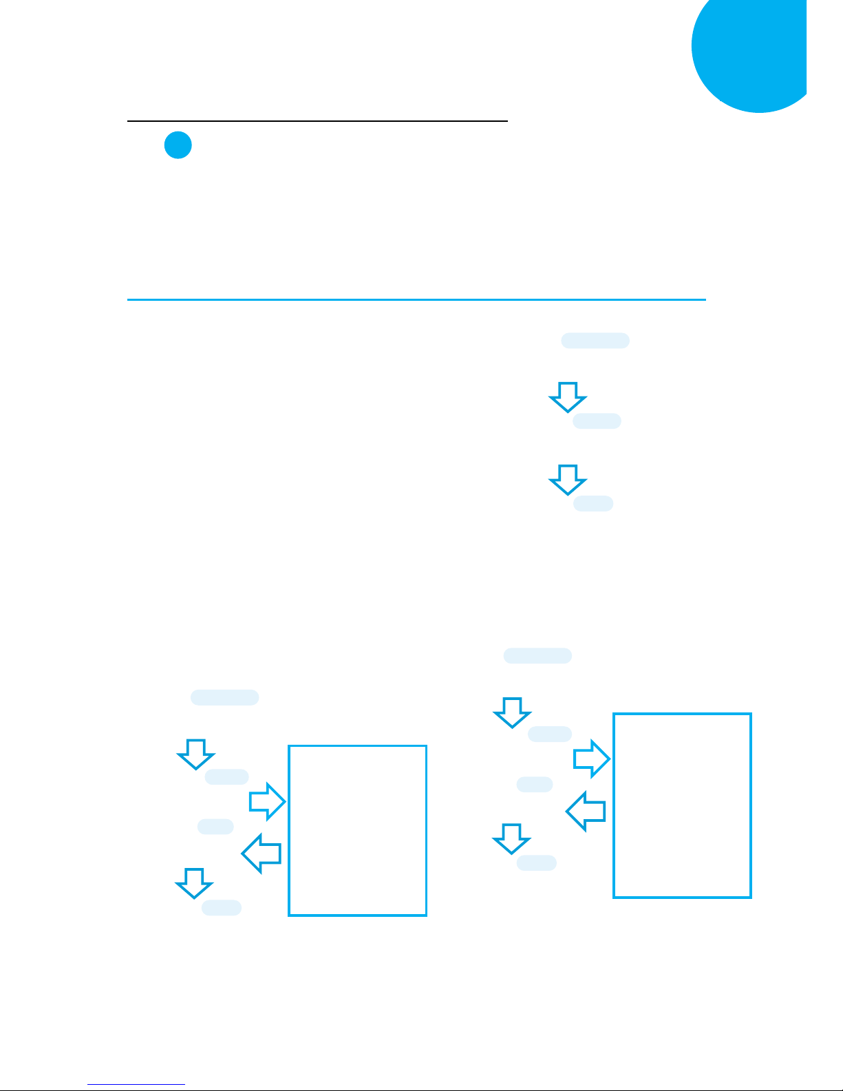
Enter 66 End
*/$%ENTR* *ZEND*
Establish a Bluetooth Connection
5
How to Re-Configure your Scanner to Work with Dongle A302
Step 1
Configure your scanner either using the utility program or scanning programming barcodes.
Select utility program to set up scanner when you expect to reduce the mistakes caused by
incautious manual operation on barcode sequences. As a substitute, scanning programming
barcodes alternatively provides a more efficient and straightforward method for programming
your device, compared to the complicated approach of using utility program.
Scanning Programming Barcodes
1-1. Configure OutputInterface of the
scanner to be A302 by scanning the
sequence of barcodes as the illustration on
the right side shows.
1-2. Retrieve Mac Address info on the side of
Bluetooth dongle A302, and then
configure Mac Address by scanning the
sequence of barcodes as the below
illustration shows.
1-3. Configure Device Name by scanning the
sequence of barcodes as the below
illustration shows.
ENTER
/$%ENTR
A302
BE1D6
END
ZEND
ENTER
/$%ENTR
BtMacAddr
B08FE
Scan the sequence of
barcodes
corresponding to the
actual MAC address
of the dongle from
Decimal/Hexadecimal
table in Appendix A.
SET
%OK
END
ZEND
ENTER
/$%ENTR
BtDevName
B14E6
SET
%OK
Scan the sequence of
barcodes
corresponding to the
desired Device Name
from
Decimal/Hexadecimal
table in Appendix A.
END
ZEND
Page 82
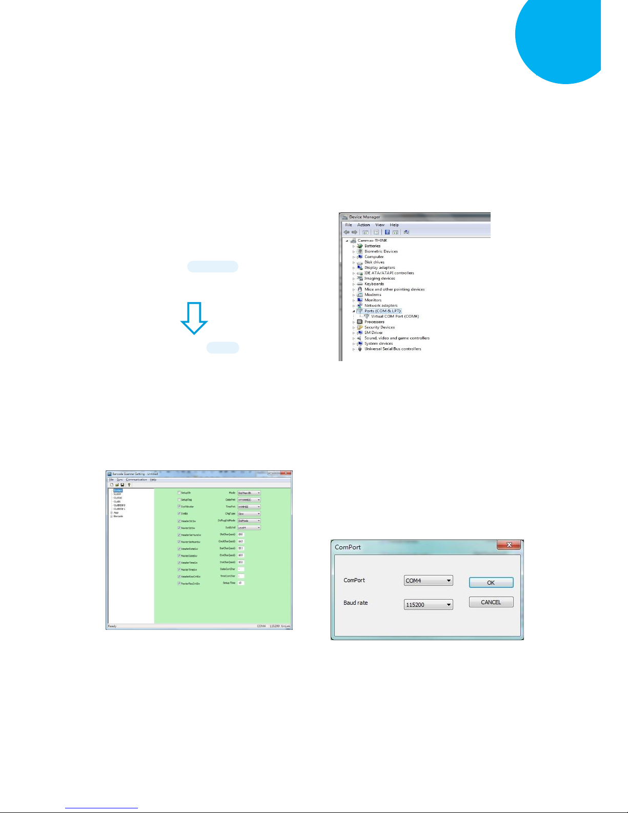
Enter 67 End
*/$%ENTR* *ZEND*
Establish a Bluetooth Connection
5
Using Utility Program
1-1. Please have your scanner connected to
Host PC using USB cable.
1-2. To create a virtual COM port for the
utility to access your scanner, Read
Enter label > scan ISP barcode. The
scanner will emit one long sound and six
short, rapid sounds followed by two short,
slow sounds as a successful attempt.
1-3. Go to Control Panel> Device Manager.
The created virtual COM port would be
found in Ports (COM & LPT) group. In
the example, COM3 is used as the virtual
COM port.
1-4. Invoke the utility program located in
Product CD.
1-5. Select Sync> Property. In ComPort
pop-up dialogue box, configure ComPort
properly according to the virtual COM
port created in Step 3 and leave Baud
rate with its default. In the example,
configure it with COM4.
ISP
ZISP
ENTER
/$%ENTR
Page 83
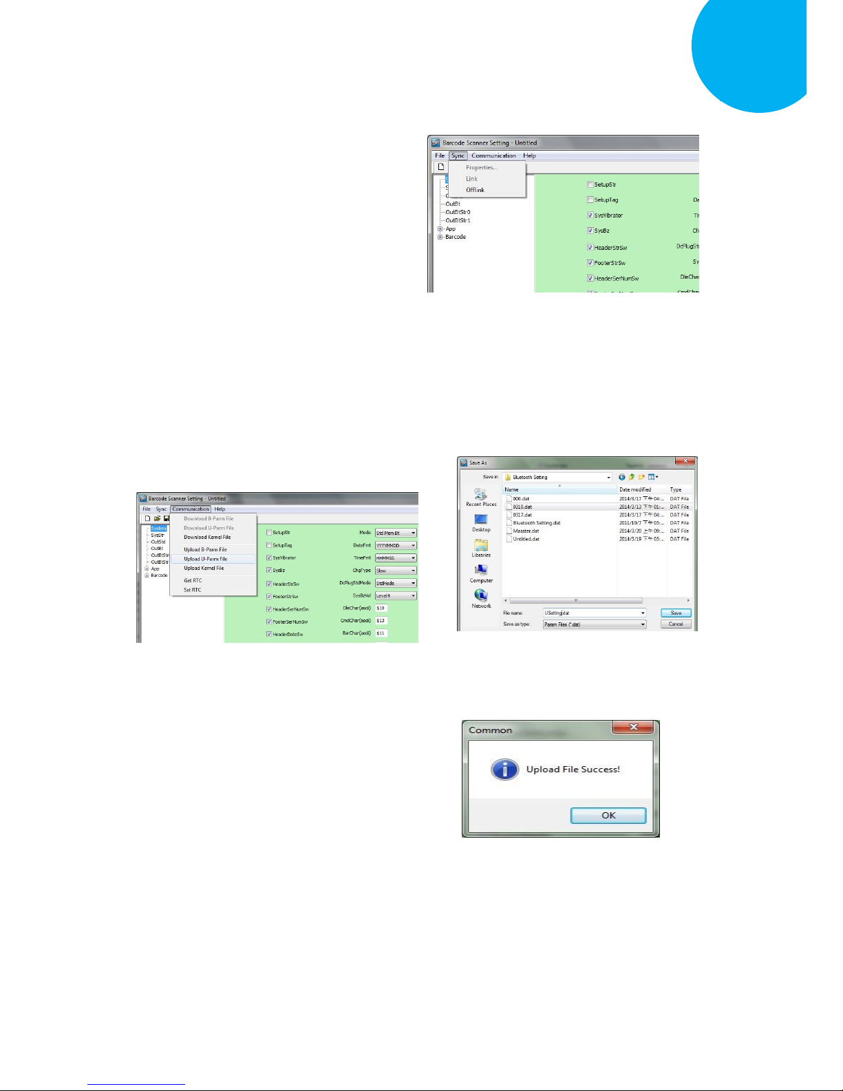
Enter 68 End
*/$%ENTR* *ZEND*
Establish a Bluetooth Connection
5
1-6. Select Sync> Link to link the scanner
with the utility program. Once the link is
successfully established, Link/Property
options in Sync menu will be greyed out
and the status bar will show associated
information.
1-7. Before configuring your scanner, you
need to upload the scanner status first to
ensure the current setting will not be
overwritten. In doing so, Select
Communication> Upload U-Parm File.
1-8. As a Save as dialogue box pops up,
specify the file name and click Save
button.
1-9. After the upload process is done, a
message box will appear to indicate
whether the operation is done
successfully.
Page 84
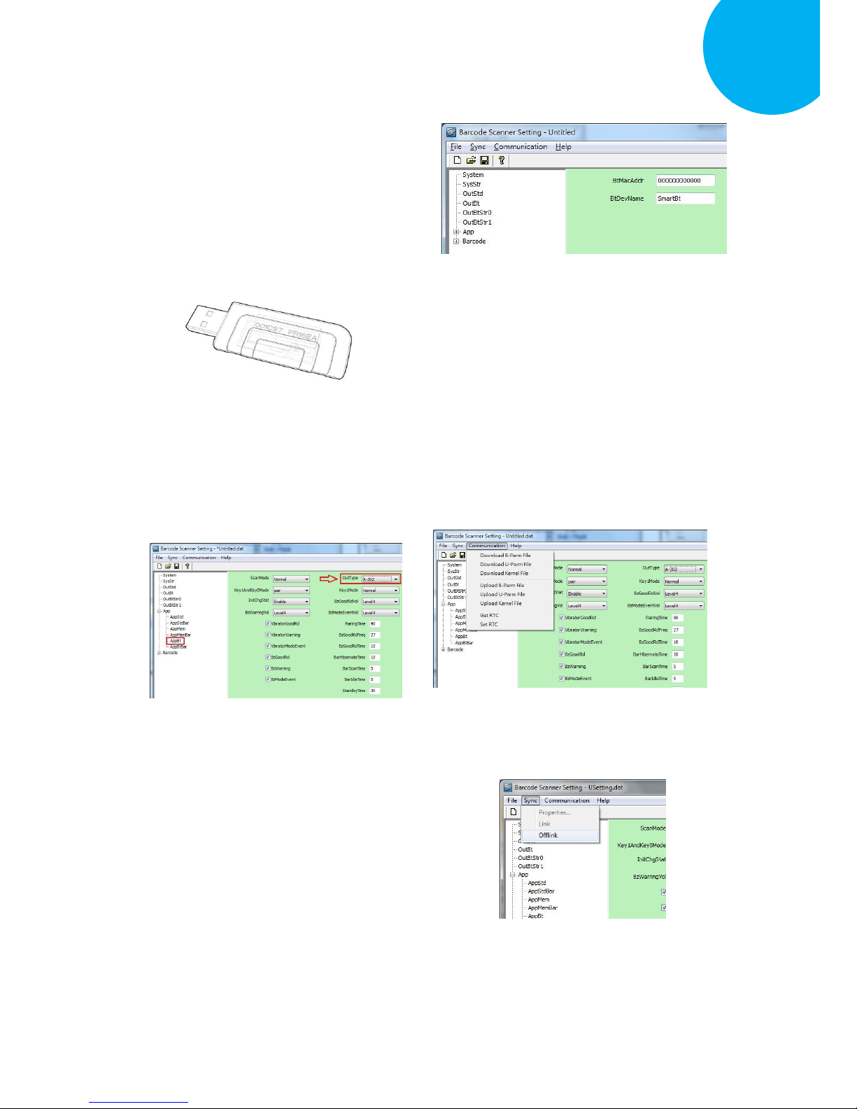
Enter 69 End
*/$%ENTR* *ZEND*
Establish a Bluetooth Connection
5
1-10. Click on OutBtStr1 item of the tree view
in the left panel. Afterwards, Configure
BtDevName according to your reference,
but associate BtMacAddr with MAC
address information which is clearly
marked on the side of Bluetooth dongle
A303. In this example, the MAC address
is 001C97FR16EA.
1-11. In the tree view, select App>AppBt. In
the right panel, select A302 in the
OutType combo box. Click Save icon on
the toolbar to save your settings.
1-12. Select Communication>Download
U-Parm file to apply the customized
settings to the scanner.
1-13. Select Sync> Offlink to complete the
configuration.
Page 85

Enter 70 End
*/$%ENTR* *ZEND*
Establish a Bluetooth Connection
5
Step 2
Pair the scanner with third-party Bluetooth dongle.
2-3. Please have your scanner switch to Bluetooth mode. Choose one of two alternatives listed
below to help you achieve the attempt.
Using Button Triggers
When the current mode indicator does not flash blue, please hold Scan Button long enough to
have LED light turn a solid color. Then, after a release of Scan Button, you can tell which
operation mode it switches to by observing LED color. Repeat the steps printed in bold if
blue LED does not blink after releasing the Scan Button.
Scanning Programming Barcodes
Scan the below barcode.
2-4. Pair your scanner with third-party Bluetooth dongle by either of two options suggested below.
Using Button Triggers
After holding small trigger till blue LED starts blinking rapidly, press down Scan Button
without releasing Small Trigger. Then releasing Scan button and Small trigger at the same time
will initiate the pairing process.
Scanning Programming Barcodes
Scan the below barcode.
To BT Mode
ZTOB
BT Pairing
ZPAR
ENTER
/$%ENTR
ENTER
/$%ENTR
Page 86

Enter 71 End
*/$%ENTR* *ZEND*
Establish a Bluetooth Connection
5
Step 3
Launch the existing text editing application to
receive barcode data.
Page 87

Enter 72 End
*/$%ENTR* *ZEND*
Editing General Settings
6
6. General Configuration
This chapter will provide setup barcodes regarding the general settings, and elaborate how these
configurations are going to take effect in terms of the scanner operation.
Page 88

Enter 73 End
*/$%ENTR* *ZEND*
Editing General Settings
6
6-1. Host Interface
6-1-1. Restore the Setting
Scan the below barcode to restore the device back to the default settings, but to leave
interface-related configurations unchanged.
6-1-2. Restore the Symbology Setting
Scan the below barcode to restore the symbologies to the default settings.
6-1-3. Retrieve Firmware Information
Scan the below barcode to retrieve firmware information, including engine version, firmware
version, and Bluetooth module version.
6-1-4. Abort the Configuration
Scan the below barcode to terminate the current operation and exit the configuration mode.
6-1-5. Update Firmware
This setup barcode allows you to attemp a firmware update via the utility program. After
securing the interface into the scanner and the PC USB port, scan the below barcode to
create a virtual COM port which avails the utility of the access of the device.
Default
ZADE
Version
ZVER
Barcode Default
ZDEF
Abort
ZEXT
ISP
ZISP
Page 89

Enter 74 End
*/$%ENTR* *ZEND*
Editing General Settings
6
6-1-6. Enable/Disable Automatic Battery Charger
By default, the device will automatically initiate the charging process to ensure a sufficient
battery level after connected with the interface cable. Scan the barcode to enable or disable
automatic battery charger. If the automatic battery charger is disabled, scan the barcode to
turn it on; Conversely, scan the barcode to turn off the automatic charger when the function
is enabled.
6-1-7. Bluetooth Pairing
Scan the barcode to initiate the Bluetooth pairing process.
6-2. System Control
6-2-1. Available Operation Modes
Taking into account the diversity of the business activities, three operation modes are
provided to improve efficiency at work. The list of setup barcodes below shows varied
selections of mode combinations, including 2in1 and 3in1 functions, for you to choose from.
Scan the appropriate barcode to determine availability of operation modes.
Memory
A40C1
Cable
A40C0
Bluetooth
A40C3
Cable+Mem
A40C2
Charge On/Off
ZCHG
BtPairing
ZPAR
Page 90

Enter 75 End
*/$%ENTR* *ZEND*
Editing General Settings
6
6-2-2. Set Date Format
Scan the appropriate barcode to specify the date format.
YYYYMMDD
A42C0
MMDDYYYY
A42C1
DDMMYYYY
A42C2
Cable+BT
A40C4
Mem+BT
A40C5
Cable+Mem+BT
A40C6
YYMMDD
A42C3
MMDDYY
A42C4
DDMMYY
A42C5
Page 91

Enter 76 End
*/$%ENTR* *ZEND*
Editing General Settings
6
6-2-3. Set Time Format
Scan the appropriate barcode to specify the time format.
6-2-4. Set Charge Rate
Scan the appropriate barcode to specify the charge rate.
6-2-5. Set the Workflow of Operation Modes Switch
This parameter specifies how the device switches among different operation modes. With
StdMode setting, the operation mode will compulsorily switch to Cable mode when the
device is connected with a cable. At the moment, the scanner is not able to switch to other
modes unless the cable is unplugged from the scanner. Without the cable plugged in, the
device will switch back to the previous operation mode, and Cable mode becomes
unavailable. Conversely, if you wish the operation mode would remain the same or demand
full availability of three operation modes, no matter whether the cable is plugged in or not,
then scan Disable label to achieve the attempt.
Slow
A4380
Quick
A4381
HHMMSS
A42A0
HHMM
A42A1
MMSS
A42A2
Disable
A4320
StdMode
A4321
Page 92

Enter 77 End
*/$%ENTR* *ZEND*
Editing General Settings
6
6-2-6. Enable/Disable Buzzer
The warning buzzer emits a sound when a warning occurs. Scan the appropriate barcode to
disable or enable the buzzer.
6-2-7. Set the Warning Buzzer Volume
Scan the appropriate barcode to specify the volume of the warning buzzer. The higher level
indicates the louder sound.
6-2-8. Enable/Disable Vibrator
Vibrator functions as the warning buzzer yet sends a warning signal by vibration. Scan the
appropriate barcode to disable or enable the warning vibrator.
Level1
A4580
Level2
A4581
Level3
A4582
Level4
A4583
Disable
A4540
Enable
A4541
Disable
A4550
Enable
A4551
Page 93

Enter 78 End
*/$%ENTR* *ZEND*
Editing General Settings
6
6-2-9. Enable/Disable Header
Headers refer to additional information, including serial number, date, time and so on, which
precedes the decoded message while saved barcodes are transmitted in Memory mode. Scan
the appropriate barcode to determine whether or not to send out the header information as
part of transmitted data.
6-2-10. Enable/Disable Serial Number Info in the Header
Scan the appropriate barcode to determine whether or not to send out serial number
information as part of header information.
6-2-11. Enable/Disable Date Info in the Header
Scan the appropriate barcode to determine whether or not to send out date information as
part of header information.
Disable
A4600
Enable
A4601
Disable
A4610
Enable
A4611
Disable
A4620
Enable
A4621
Page 94

Enter 79 End
*/$%ENTR* *ZEND*
Editing General Settings
6
6-2-12. Enable/Disable Time Info in the Header
Scan the appropriate barcode to determine whether or not to send out time information as
part of header information.
6-2-13. Enable/Disable Record Count Info in the Header
Record count information refers to the total number of scanned barcodes. Read the
appropriate barcode to determine whether or not to send out the record count as part of
header information.
6-2-14. Enable/Disable Footer
Footers refer to additional information which is appended to the decoded message while
saved barcodes are transmitted in Memory mode. Scan the appropriate barcode to
determine whether or not to send out the footer information as part of transmitted data.
Disable
A4630
Enable
A4631
Disable
A4640
Enable
A4641
Disable
A4700
Enable
A4701
Page 95

Enter 80 End
*/$%ENTR* *ZEND*
Editing General Settings
6
6-2-15. Enable/Disable Serial Number Info in the Footer
Scan the appropriate barcode to determine whether or not to send out serial number
information as part of footer information.
6-2-16. Enable/Disable Date Info in the Footer
Scan the appropriate barcode to determine whether or not to send out date information as
part of footer information.
6-2-17. Enable/Disable Time Info in the Footer
Scan the appropriate barcode to determine whether or not to send out time information as
part of footer information.
Disable
A4720
Enable
A4721
Disable
A4730
Enable
A4731
Disable
A4710
Enable
A4711
Page 96

Enter 81 End
*/$%ENTR* *ZEND*
Editing General Settings
6
6-2-18. Enable/Disable Record Count Info in the Footer
Record count information refers to the total number of scanned barcodes. Read the
appropriate barcode to determine whether or not to send out the record count as part of
footer information.
6-2-19. Set Date & Time
Scan the below barcode to set up date and time on the scanner. While associating the
parameter with the preferred value, please pay attention to the time and date format you
specify separately in Section 6-2-2 and Section 6-2-3 and then arrange related scan
sequences in the correct format to work out the configuration.
Procedure
(1) Scan Enter barcode.
(2) Scan Set Date & Time barcode to set time and date on the device.
(3) Please refer to Decimal/Hexadecimal Table in the appendix to scan compound
hexadecimal value barcodes representing the desired date and time. For instance,
to configure date to be “2014/09/09”and time to “14:13:12”, scan
1,4,0,9,0,9,1,4,1,3,1 and then 2 to assign the specified hexadecimal value
“140909141312”.
(4) Scan SET barcode to complete the variable-binding operation.
(5) Scan End barcode to complete the configuration.
Disable
A4740
Enable
A4741
Set Date & Time
ZCLK
Page 97

Enter 82 End
*/$%ENTR* *ZEND*
Editing General Settings
6
6-2-20. Set Date Separator
Date separator refers to the specified character which is used to format date data by
dividing into different elements of years, months, and days. A customized date format with
date separator will greatly increase readability.
Procedure
(6) Scan Enter barcode.
(7) Scan DateConChar barcode to configure date separator.
(8) Please refer to ASCII Code Table and Decimal/Hexadecimal Table in the appendix
to scan hexadecimal value barcodes representing the desired string which has to be
1 character in length. For instance, to use “:” character to break down Date
information, scan 3 first and then A to assign the specified hexadecimal value
“3A”.
(9) Scan SET barcode to complete the variable-binding operation.
(10) Scan End barcode to complete the configuration.
6-2-21. Set Time Separator
Time separator refers to the specified character which is used to format time data by
dividing into different elements of hours, minutes, and seconds. A customized time format
with time separator will greatly increase readability.
TimeConChar
A57E2
(Length: 1 digit)
DateConChar
A56E2
(Length: 1 digit)
Page 98

Enter 83 End
*/$%ENTR* *ZEND*
Editing General Settings
6
Procedure
(1) Scan Enter barcode.
(2) Scan TimeConChar barcode to configure time separator.
(3) Please refer to ASCII Code Table and Decimal/Hexadecimal Table in the appendix
to scan hexadecimal value barcodes representing the desired string which has to be
1 character in length. For instance, to use “:” character to break down Time
information, scan 3 first and then A to assign the specified hexadecimal value
“3A”.
(4) Scan SET barcode to complete the variable-binding operation.
(5) Scan End barcode to complete the configuration.
6-2-22. Set Time-out Period for Configuration Mode
The timeout period mentioned here refers to the length of time the device is allowed to
remain idle ever since ENTER barcode is scanned to initiate Configuration mode. Once
the time-out session expires, the scanner will automatically exit Configuration mode. This
parameter allows you to configure the timeout limit which works best for you.
Procedure
(1) Scan Enter barcode.
(2) Scan SetupTime barcode to configure the length of the timeout session.
(3) Please refer to Decimal/Hexadecimal Table in the appendix to scan decimal value
barcodes representing the desired decimal value in the range of 0 to 255. For
instance, to set timeout period to 1 second, then scan 1 to assign the specified
decimal value “1”.
(4) Scan SET barcode to complete the variable-binding operation.
(5) Scan End barcode to complete the configuration.
SetupTime
A5FE0
(Length: 1 digit / Range: 0-255/ Unit: 1000ms)
Page 99

Enter 84 End
*/$%ENTR* *ZEND*
Editing General Settings
6
6-2-23. Set Header Information
Header information refers to additional messages preceding to data output while the
scanned barcodes are sent out in Memory mode. This special parameter allows you to
customize your own custom header to add clarity of transmitted data.
Procedure
(1) Scan Enter barcode.
(2) Scan Header barcode to configure the length of the timeout session.
(3) Please refer to ASCII Code Table and Decimal/Hexadecimal Table in the
appendix to scan hexadecimal value barcodes representing the desired string
which has to be at most 12 characters in length. For instance, to place the
employee name "Mark" in the header section, scan 4, D, 6, 1, 7, 2, 6 followed by
B to assign the specified hexadecimal value “4D61726B”.
(4) Scan SET barcode to complete the variable-binding operation.
(5) Scan End barcode to complete the configuration.
Header
A60E6
(Length: 12 digits)
Page 100

Enter 85 End
*/$%ENTR* *ZEND*
Editing General Settings
6
6-2-24. Set Footer Information
Footer information refers to additional messages which are appended to data output while
the scanned barcodes are sent out in Memory mode. This special parameter allows you to
customize your own custom footer to add clarity of transmitted data.
Procedure
(1) Scan Enter barcode.
(2) Scan Footer barcode to configure the length of the timeout session.
(3) Please refer to ASCII Code Table and Decimal/Hexadecimal Table in the appendix
to scan hexadecimal value barcodes representing the desired string which has to be
at most 12 characters in length. For instance, to place the employee name "Mark"
in the footer section, scan 4, D, 6, 1, 7, 2, 6 followed by B to assign the specified
hexadecimal value “4D61726B”.
(4) Scan SET barcode to complete the variable-binding operation.
(5) Scan End barcode to complete the configuration.
6-3. Scanner Commands
To perform certain special tasks, you sometimes will use Command Prompt commands to
communicate with the device instead of having your scanner read a sequence of setup
barcodes listed in the manual. In the case like this, you possibly need to rely on escape
characters, no matter predefined or customized, to notify the decoder of the additional
interpretation on the text following prefixed escape characters. The below configurable
parameters allow you to define your own escape characters while you work with a terminal
program to send out command strings to the scanner.
Footer
A70E6
(Length: 12 digits)
 Loading...