

Page 1
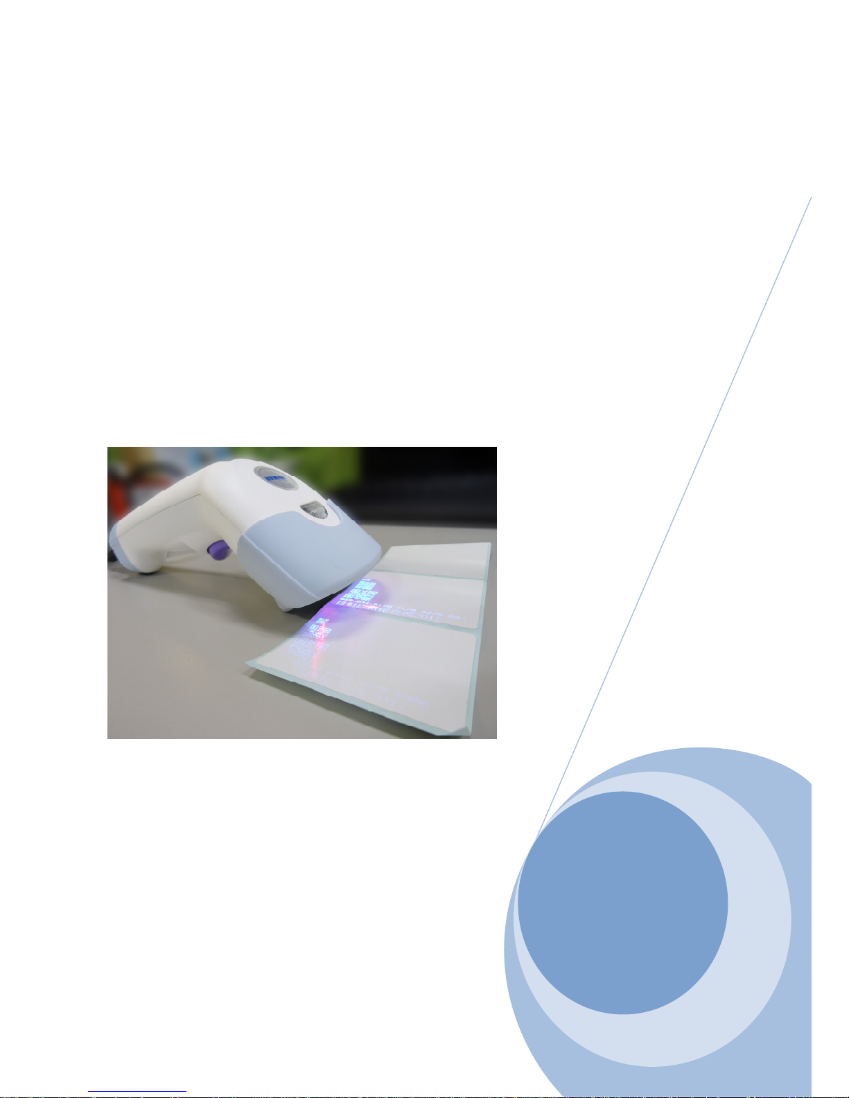
2D Handheld Barcode
Scanner User Manual
Ver:1.4
Copyright© March.14.2018 All rights reserved
Page 2

2
Index
Chapter 1: GET STARTED ............................................................................. 9
1-1 Reading Techniques ...................................................................... 10
1-2 Setting Custom Default ................................................................. 11
1-3 Reset the Custom Defaults ........................................................... 12
Chapter 2: PROGRAM THE INTERFACE .................................................... 13
2-1 Introduction .................................................................................... 14
2-2 Program the Interface - Plug and Play ......................................... 14
2-2-1 RS232 serial port ................................................................ 14
2-2-2 USB PC or Macintosh Keyboard ......................................... 15
2-2-3 USB HID ............................................................................. 15
2-2-4 USB Serial .......................................................................... 16
2-3 Keyboard Country Layout ............................................................. 17
2-3-1 Keyboard Countries ............................................................ 17
2-4 Keyboard Style ............................................................................... 29
2-5 Keyboard Conversion .................................................................... 30
2-6 Control Character Output .............................................................. 31
2-7 Keyboard Modifiers ........................................................................ 32
2-8 RS232 Modifiers ............................................................................. 34
2-8-1 Baud Rate ........................................................................... 34
2-8-2 RS232 Word Length Data Bits, Stop Bits, and Parity .......... 36
2-8-3 RS232 Receiver Time-Out .................................................. 38
2-8-4 RS232 Handshaking ........................................................... 39
2-8-5 RS232 Timeout ................................................................... 40
2-8-6 XON/XOFF ......................................................................... 40
2-8-7 ACK/NAK ............................................................................ 41
2-8-8 RS232 Stop Mode .............................................................. 41
Chapter 3: INPUT/OUTPUT SETTINGS ....................................................... 42
3-1 Power Up Beeper ........................................................................... 44
3-2 Beep on BEL Character ................................................................. 44
3-3 Trigger Click ................................................................................... 45
3-4 Good Read and Error Indicators ................................................... 45
3-4-1 Beeper – Good Read .......................................................... 45
3-4-2 Beeper Volume – Good Read ............................................. 46
3-4-3 Beeper Pitch – Good Read ................................................. 47
3-4-4 Beeper Pitch – Error ........................................................... 47
3-4-5 Beeper Duration – Good Read ........................................... 48
3-4-6 LED – Good Read .............................................................. 49
3-4-7 Number of Beeps – Good Read .......................................... 49
3-4-8 Number of Beeps – Error .................................................... 50
3-4-9 Good Read Delay ............................................................... 50
Page 3

3
Index
3-4-10 User-Specified Good Read Delay ..................................... 51
3-5 Manual Trigger Mode ..................................................................... 52
3-5-1 LED Illumination - Manual Trigger ....................................... 52
3-6 Character Activation Mode ............................................................ 53
3-6-1 Activation Character ............................................................ 53
3-6-2 End Character Activation After Good Read ......................... 54
3-6-3 Character Activation Timeout .............................................. 54
3-7 Character Deactivation Mode ........................................................ 55
3-7-1 Deactivation Character ....................................................... 55
3-8 Serial Trigger Mode ........................................................................ 56
3-8-1 Read Time-Out ................................................................... 56
3-9 Presentation Mode ......................................................................... 57
3-9-1 Idle Illumination - Presentation Mode .................................. 57
3-9-2 Presentation Sensitivity....................................................... 58
3-9-3 Presentation Centering ....................................................... 59
3-10 CodeGate ...................................................................................... 61
3-11 Mobile Phone Read Mode ............................................................ 61
3-12 Poor Quality Codes ...................................................................... 62
3-12-1 Poor Quality 1D codes ...................................................... 62
3-12-2 Poor Quality PDF Codes ................................................... 62
3-13 Hands Free Time-Out ................................................................... 63
3-14 Reread Delay in Presentation Mode ........................................... 63
3-15 User-Specified Reread Delay ...................................................... 64
3-16 2D Reread Delay ........................................................................... 65
3-17 Illumination Lights ....................................................................... 66
3-18 Aimer Delay .................................................................................. 66
3-18-1 User-Specified Aimer Delay .............................................. 67
3-19 Aimer Mode ................................................................................... 67
3-20 Centering ...................................................................................... 68
3-21 Multiple Symbols.......................................................................... 70
3-22 No Read ........................................................................................ 71
3-23 Video Reverse .............................................................................. 71
3-24 Working Orientation ..................................................................... 72
Chapter 4: DATA EDITING ........................................................................... 74
4-1 Prefix/Suffix Overview ................................................................... 75
4-1-1 Points to Keep In Mind ........................................................ 75
4-1-2 To Add a Prefix or Suffix ..................................................... 76
4-1-3 Example : Add a Tab Suffix to All Symbologies ................... 76
4-1-4 To Clear One or All Prefixes or Suffixes .............................. 77
4-1-5 To Add a Carriage Return Suffix to All Symbologies ........... 77
Page 4

4
Index
4-2 Prefix Selections ............................................................................ 78
4-4 Function Code Transmit ................................................................ 79
4-5 Intercharacter, Interfunction, and Intermessage Delays ............. 80
4-5-1 Intercharacter Delay ........................................................... 80
4-5-2 User Specified Intercharacter Delay ................................... 81
4-5-3 Interfunction Delay .............................................................. 82
4-5-4 Intermessage Delay ............................................................ 83
Chapter 5: DATA FORMATTING .................................................................. 84
5-1 Data Format Editor Introduction ................................................... 85
5-2 Add a Data Format ......................................................................... 86
5-2-1 Other Programming Selections ........................................... 87
5-3 Terminal ID Table ........................................................................... 88
5-4 Data Format Editor Commands .................................................... 88
5-4-1 Send Commands ................................................................ 88
5-4-2 Move Commands ................................................................ 91
5-4-3 Search Commands ............................................................. 92
5-4-4 Miscellaneous Commands .................................................. 94
5-5 Data Formatter ............................................................................... 97
5-6 Primary/Alternate Data Formats ................................................... 98
Chapter 6: SYMBOLOGIES.......................................................................... 99
6-1 All Symbologies ........................................................................... 103
6-2 Message Length Description ...................................................... 104
6-3 Codabar ........................................................................................ 105
6-3-1 Codabar On/Off ................................................................ 105
6-3-2 Codabar Start/Stop Characters ......................................... 105
6-3-3 Codabar Check Character ................................................ 106
6-3-4 Codabar Concatenation .................................................... 107
6-3-5 Codabar Message Length ................................................ 108
6-4 Code 39 ......................................................................................... 109
6-4-1 Code 39 On/Off ................................................................. 109
6-4-2 Code 39 Start/Stop Characters ......................................... 109
6-4-3 Code 39 Check Character ................................................ 110
6-4-4 Code 39 Message Length ................................................. 111
6-4-5 Code 39 Append ............................................................... 111
6-4-6 Code 32 Pharmaceutical ( PARAF ) .................................. 112
6-4-7 Full ASCII .......................................................................... 112
6-4-8 Code 39 Code Page ......................................................... 113
6-5 Interleaved 2 of 5 .......................................................................... 114
6-5-1 Interleaved 2 of 5 On/Off ................................................... 114
6-5-2 Check Digit ....................................................................... 114
Page 5

5
Index
6-5-3 Interleaved 2 of 5 Message Length ................................... 115
6-6 NEC 2 of 5 ..................................................................................... 116
6-6-1 NEC 2 of 5 On/Off ............................................................. 116
6-6-2 Check Digit ....................................................................... 116
6-6-3 NEC 2 of 5 Message Length ............................................. 117
6-7 Code 93 ......................................................................................... 118
6-7-1 Code 93 On/Off ................................................................. 118
6-7-2 Code 93 Message Length ................................................. 118
6-7-3 Code 93 Append ............................................................... 119
6-7-4 Code 93 Code Page ......................................................... 120
6-8 Straight 2 of 5 Industrial ( three-bar start/stop ) ........................ 121
6-8-1 Straight 2 of 5 Industrial On/Off......................................... 121
6-8-2 Straight 2 of 5 Industrial Message Length ......................... 121
6-9 Straight 2 of 5 IATA ( two-bar start/stop ) ................................... 122
6-9-1 Straight 2 of 5 IATA On/Off ................................................ 122
6-9-2 Straight 2 of 5 IATA Message Length ................................ 123
6-10 Matrix 2 of 5 ................................................................................ 124
6-10-1 Matrix 2 of 5 On/Off ........................................................ 124
6-10-2 Matrix 2 of 5 Message Length ......................................... 124
6-11 Code 11 ........................................................................................ 125
6-11-1 Code 11 On/Off ............................................................... 125
6-11-2 Check Digits Required .................................................... 125
6-11-3 Code 11 Message Length ............................................... 126
6-12 Code 128 ..................................................................................... 127
6-12-1 Code 128 On/Off ............................................................. 127
6-12-2 ISBT 128 Concatenation ................................................. 127
6-12-3 Code 128 Message Length ............................................. 128
6-12-4 Code 128 Append ........................................................... 128
6-12-5 Code 128 Code Page ..................................................... 129
6-13 GS1-128 ....................................................................................... 129
6-13-1 GS1-128 On/Off .............................................................. 129
6-13-2 GS1-128 Message Length .............................................. 130
6-14 UPC-A .......................................................................................... 131
6-14-1 UPC-A On/Off ................................................................. 131
6-14-2 Convert UPC-A to EAN-13 .............................................. 131
6-14-3 UPC-A Check Digit ......................................................... 132
6-14-4 UPC-A Number System .................................................. 132
6-14-5 UPC-A Addenda ............................................................. 133
6-14-6 UPC-A Addenda Required .............................................. 133
6-14-7 UPC-A Addenda Separator ............................................. 134
Page 6

6
Index
6-15 UPC-A/EAN-13 with Extended Coupon .................................... 135
6-16 Coupon GS1 DataBar Output .................................................... 136
6-17 UPC-E .......................................................................................... 137
6-17-1 UPC-E0/UPC-E1 On/Off ................................................. 137
6-17-2 UPC-E0 Expand ............................................................. 138
6-17-3 UPC-E0 Addenda Required ............................................ 138
6-17-4 UPC-E0 Addenda Separator ........................................... 139
6-17-5 UPC-E0 Check Digit ....................................................... 139
6-17-6 UPC-E0 Leading Zero .................................................... 140
6-17-7 UPC-E0 Addenda ........................................................... 140
6-18 EAN/JAN-13 ................................................................................ 142
6-18-1 EAN/JAN-13 On/Off ........................................................ 142
6-18-2 EAN/JAN-13 Check Digit ................................................ 142
6-18-3 EAN/JAN-13 Addenda .................................................... 143
6-18-4 EAN/JAN-13 Addenda Required ..................................... 143
6-18-5 EAN/JAN-13 Addenda Separator .................................... 144
6-18-6 ISBN Translate ................................................................ 144
6-19 EAN/JAN-8 .................................................................................. 146
6-19-1 EAN/JAN-8 On/Off .......................................................... 146
6-19-2 EAN/JAN-8 Check Digit .................................................. 146
6-19-3 EAN/JAN-8 Addenda ...................................................... 147
6-19-4 EAN/JAN-8 Addenda Required ....................................... 147
6-19-5 EAN/JAN-8 Addenda Separator...................................... 148
6-20 MSI ............................................................................................... 149
6-20-1 MSI On/Off ...................................................................... 149
6-20-2 MSI Message Length ...................................................... 149
6-20-3 MSI Check Character ..................................................... 150
6-21 GS1 Databar Omnidirectional ................................................... 152
6-21-1 GS1 DataBar Omnidirectional On/Off ............................. 152
6-22 GS1 Databar Limited .................................................................. 152
6-22-1 GS1 Databar Limited On/Off ........................................... 152
6-23 GS1 Databar Expanded ............................................................. 153
6-23-1 GS1 Databar Expanded On/Off ...................................... 153
6-23-2 GS1 Databar Expanded Message Length ...................... 153
6-24 Codablock A ............................................................................... 155
6-24-1 Codablock A On/Off ........................................................ 155
6-24-2 Codablock A Message Length ........................................ 155
6-25 Codablock F ............................................................................... 156
6-25-1 Codablock F On/Off ........................................................ 156
6-25-2 Codablock F Message Length ........................................ 156
Page 7

7
Index
6-26 PDF417 ........................................................................................ 158
6-26-1 PDF417 On/Off ............................................................... 158
6-26-2 PDF417 Message Length ............................................... 158
6-27 Macro PDF417 ............................................................................ 159
6-28 MicroPDF417 .............................................................................. 159
6-28-1 MicroPDF417 On/Off ...................................................... 159
6-28-2 MicroPDF417 Message Length ...................................... 160
6-29 GS1 Composite Codes .............................................................. 161
6-29-1 UPC/EAN Version ........................................................... 161
6-29-2 GS1 Composite Code Message Length ......................... 162
6-30 GS1 Emulation............................................................................ 163
6-31 TCIF Linked Code 39 (TLC39) ................................................... 164
6-32 QR Code ...................................................................................... 165
6-32-1 QR Code On/Off ............................................................. 165
6-32-2 QR Code Message Length ............................................. 165
6-32-3 QR Code Append ............................................................ 166
6-32-4 QR Code Page ............................................................... 167
6-33 Data Matrix .................................................................................. 168
6-33-1 Data Matrix On/Off .......................................................... 168
6-33-2 Data Matrix Message Length .......................................... 168
6-33-3 Data Matrix Code Page................................................... 169
6-34 Mexicode ..................................................................................... 170
6-34-1 MaxiCode On/Off ............................................................ 170
6-34-2 MaxiCode Message Length ............................................ 170
6-35 Aztec Code .................................................................................. 171
6-35-1 Aztec Code On/Off .......................................................... 171
6-35-2 Aztec Code Message Length .......................................... 171
6-35-3 Aztec Append .................................................................. 172
6-35-4 Aztec Code Page ............................................................ 173
6-36 Chinese Sensible (Han Xin) Code ............................................. 174
6-36-1 Han Xin Code On/Off ...................................................... 174
6-36-2 Han Xin Code Message Length ...................................... 174
6-37 Postal Codes-2D......................................................................... 175
6-37-1 Single 2D Postal Codes .................................................. 175
6-37-2 Combination 2D Postal Codes ........................................ 177
6-37-3 Planet Code Check Digit ................................................. 180
6-37-4 Postnet Check Digit ........................................................ 180
6-37-5 Australian Post Interpretation .......................................... 181
6-38 Postal Codes - Linear ................................................................ 182
6-38-1 China Post (Hong Kong 2 of 5) ....................................... 182
Page 8

8
Index
6-38-2 China Post (Hong Kong 2 of 5) Message Length ............ 182
6-38-3 Korea Post ...................................................................... 183
6-38-4 Korea Post Message Length........................................... 183
6-38-5 Korea Post Check Digit ................................................... 184
Chapter 7: UTILITIES ................................................................................. 185
7-1 To Add a Test Code I.D. Prefix to All Symbologies ................... 186
7-2 Show Decoder Revision .............................................................. 186
7-3 Show Scan Driver Revision ......................................................... 186
7-4 Show Software Revision ............................................................. 187
7-5 Show Data Format ........................................................................ 187
7-6 Resetting the Factory Defaults ................................................... 188
Chapter 8: SERIAL PROGRAMMING COMMANDS .................................. 189
8-1 Conventions ................................................................................. 190
8-2 Menu Command Syntax .............................................................. 190
8-2-1 Serial Command Example ................................................ 191
8-3 Trigger Commands ...................................................................... 193
8-4 Setting the Custom Defaults ....................................................... 194
8-5 Resetting the Custom Defaults ................................................... 194
8-6 Menu Commands ......................................................................... 195
Chapter 9: MAINTENANCE AND TROUBLESHOOTING .......................... 221
9-1 Repairs .......................................................................................... 222
9-1-1 Inspecting Cords and Connectors ..................................... 222
9-2 Troubleshooting ........................................................................... 222
Appendix A: Reference Charts ................................................................. 224
Symbology Charts ............................................................................. 225
Linear Symbologies .................................................................... 225
2D Symbologies ......................................................................... 227
Postal Symbologies .................................................................... 228
ASCII Conversion Chart (Code Page 1252) ...................................... 229
Lower ASCII Reference Table ............................................................ 231
ISO 2022/ISO 646 Character Replacements ..................................... 232
Keyboard Key References ................................................................. 234
Sample Symbols ................................................................................ 235
Programming Chart (Numeric code table) ....................................... 236
Programming Chart (Alphanumeric code table) .............................. 238
Page 9

9
1. GET STARTED
Chapter 1: GET STARTED
1-1 Reading Techniques
1-2 Setting Custom Default
1-3 Reset the Custom Defaults
Page 10
10
1. GET STARTED
1-1 Reading Techniques
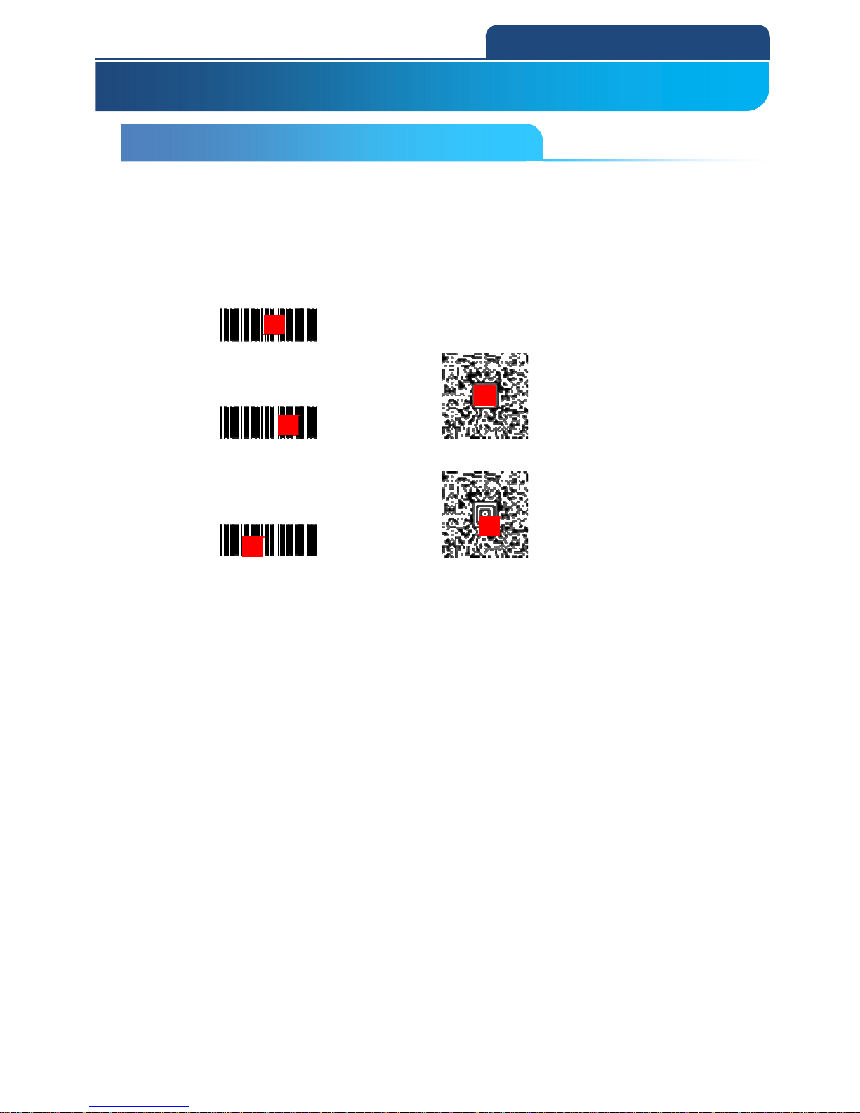
The scan engine has a view finder that projects a bright red aiming square.
The aiming beam should be centered over the bar code, but it can also be
positioned outside of the center for a good read.
Linear bar code
2D Matrix symbol
The aiming beam is smaller when the scan engine is closer to the code and
larger when it is farther from the code. Symbologies with smaller bars or
elements (mil size) should be read closer to the unit.
Symbologies with larger bars or elements (mil size) should be read farther
from the unit.
To read single or multiple symbols (on a page or on an object), hold the scan
engine at an appropriate distance from the target, pull the trigger, and center
the aiming beam on the symbol.
If the code being scanned is highly reflective (e.g., laminated), it may be
necessary to tilt the code up 15° to 18° to prevent unwanted reflection.
1. GET STARTED
1-1 Reading Techniques
Page 11
11
1. GET STARTED
1-2 Setting Custom Default
You have the ability to create a set of menu commands as your own, custom
defaults.
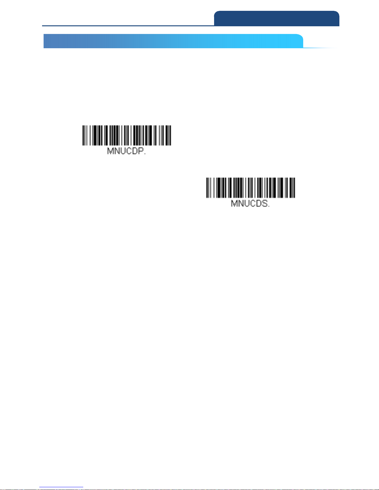
To do so, scan the Set Custom Defaults bar code below before scanning the
menu commands for your custom defaults. If a menu command requires
scanning numeric codes from the back cover, then a Save code, that entire
sequence will be saved to your custom defaults.
When you have entered all the commands you want to save for your custom
defaults, scan the Save Custom Defaults bar code.
Set Custom Defaults
Save Custom Defaults
You may have a series of custom settings and want to correct a single setting.
To do so, just scan the new setting to overwrite the old one.
For example, if you had previously saved the setting for Beeper Volume at Low
to your custom defaults, and decide you want the beeper volume set to High,
just scan the Set Custom Defaults bar code, then scan the Beeper Volume
High menu code, and then Save Custom Defaults.
The rest of the custom defaults will remain, but the beeper volume setting will
be updated.
1-2 Setting Custom Default
Page 12

12
1. GET STARTED
1-3 Reset the Custom Defaults
If you want the custom default settings restored to your scan engine, scan the
Activate Custom Defaults bar code below.
This is the recommended default bar code for most users. It resets the scan
engine to the custom default settings.
If there are no custom defaults, it will reset the scan engine to the factory
default settings.
Any settings that have not been specified through the custom defaults will be
defaulted to the factory default settings.
Activate Custom Defaults
Note: To remove cutom defaults, see "Resetting the Factory Defaults".
1-3 Reset the Custom Defaults
Page 13

13
2. PROGRAM THE INTERFACE
Chapter 2: PROGRAM THE INTERFACE
2-1 Introduction
2-2 Program the Interface - Plug and Play
2-2-1 RS232 serial port
2-2-2 USB PC or Macintosh Keyboard
2-2-3 USB HID
2-2-4 USB Serial
2-3 Keyboard Country Layout
2-3-1 Keyboard Countries
2-4 Keyboard Style
2-5 Keyboard Conversion
2-6 Control Character Output
2-7 Keyboard Modifiers
2-8 RS232 Modifiers
2-8-1 Baud Rate
2-8-2 RS232 Word Length: Data Bits, Stop Bits, and Parity
2-8-3 RS232 Receiver Time-Out
2-8-4 RS232 Handshaking
2-8-5 RS232 Timeout
2-8-6 XON/XOFF
2-8-7 ACK/NAK
2-8-8 RS232 Stop Mode
Page 14
14
2. PROGRAM THE INTERFACE
2-1 Introduction
This chapter describes how to program your system for the desired interface.
2-2 Program the Interface - Plug and Play
Plug and Play bar codes provide instant scan engine set up for commonly
used interfaces.
Note: After you scan one of the codes, power cycle the host terminal to have
the interface in effect.
2-2-1 RS232 serial port
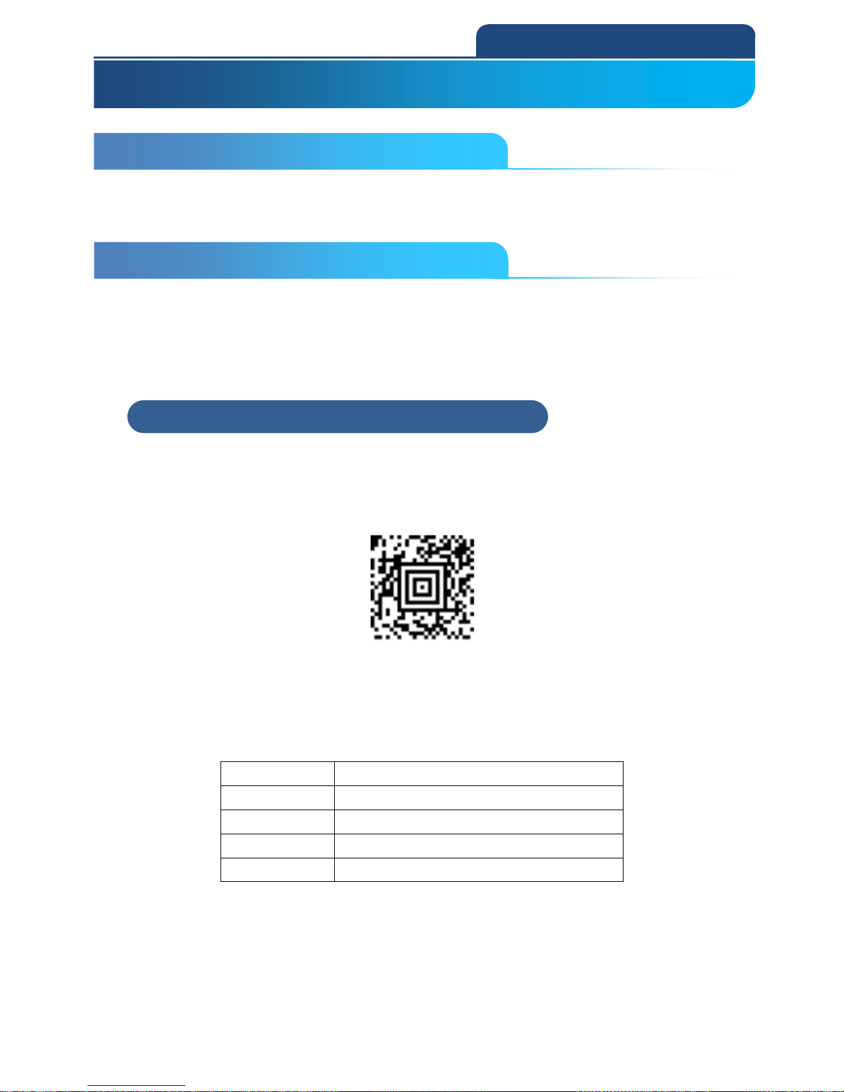
The RS232 Interface bar code is used when connecting to the serial port of a
PC or terminal. It also programs a carriage return (CR) and a line feed (LF)
suffix, baud rate, and data format as indicated below. It also changes the
trigger mode to manual.
TERMID0;232BAD9;232WRD2
RS-232 interface
And the setting parameter for RS232C is as below :
Parameter information
Baud rate 115,200bps
Data Format 8 bits, no parity, 1 stop bit
suffix CR/LF
Trigger mode Manual trigger
2-1 Introduction
2. PROGRAM THE INTERFACE
2-2 Program the interface – Plug and Play
2-2-1 RS232 serial port
Page 15
15
2. PROGRAM THE INTERFACE
2-2-2 USB PC or Macintosh Keyboard
Scan one of the following codes to program the scan engine for USB PC
Keyboard or USB Macintosh Keyboard. Scanning these codes also adds a CR
suffix. Default = USB Keyboard (PC).
USB Keyboard (PC)
USB keyboard (Mac)
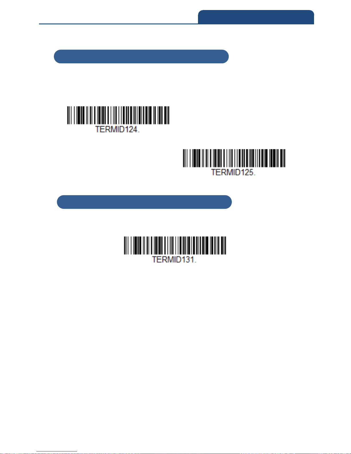
2-2-3 USB HID
Scan the following barcode to program the scanner for USB HID interface.
USB HID
2-2-2 USB PC or Macintosh Keyboard
2-2-3 USB HID
Page 16
16
2. PROGRAM THE INTERFACE
2-2-4 USB Serial
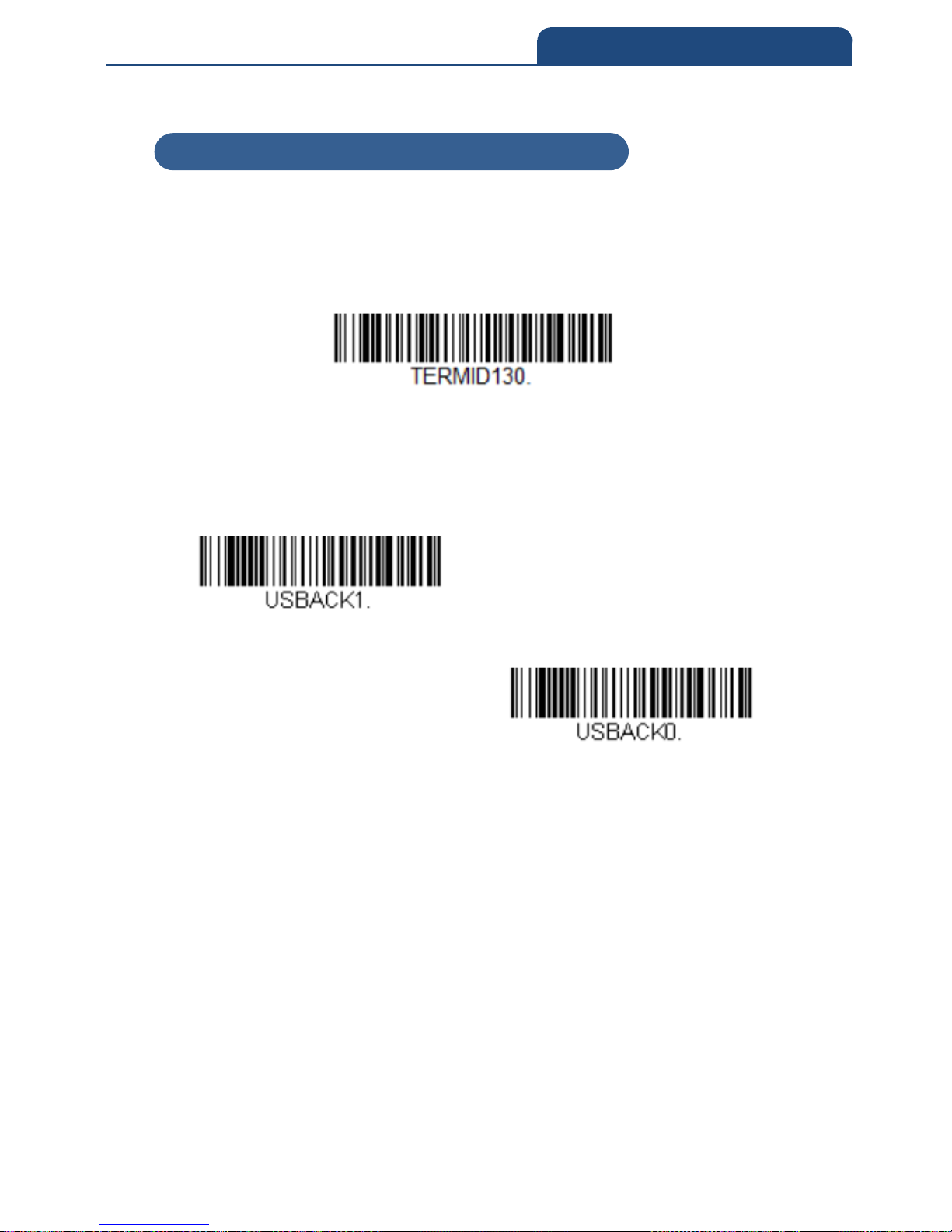
Scan the following barocode to program the scanner to emulate a regular
RS232-based COMport. If your are using a Windows OS, you will need to a
driver. Apple Machintosh computers recognize the scanner as a USB CDC
class device and automatically use a class driver.
USB serial
Note: No extra configuration (e.g., baud rate) is necessary.
Below is optional parameter for ACK/NAK setting
ACK/NAK Mode On
ACK/NAK Mode off
2-2-4 USB Serial
Page 17
17
2. PROGRAM THE INTERFACE
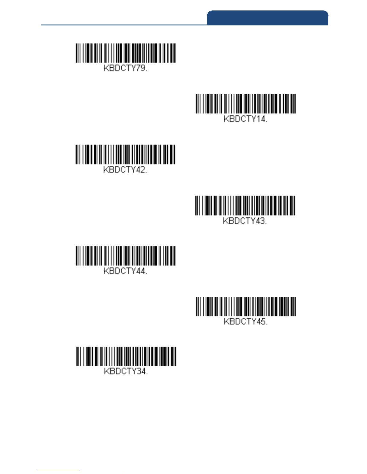
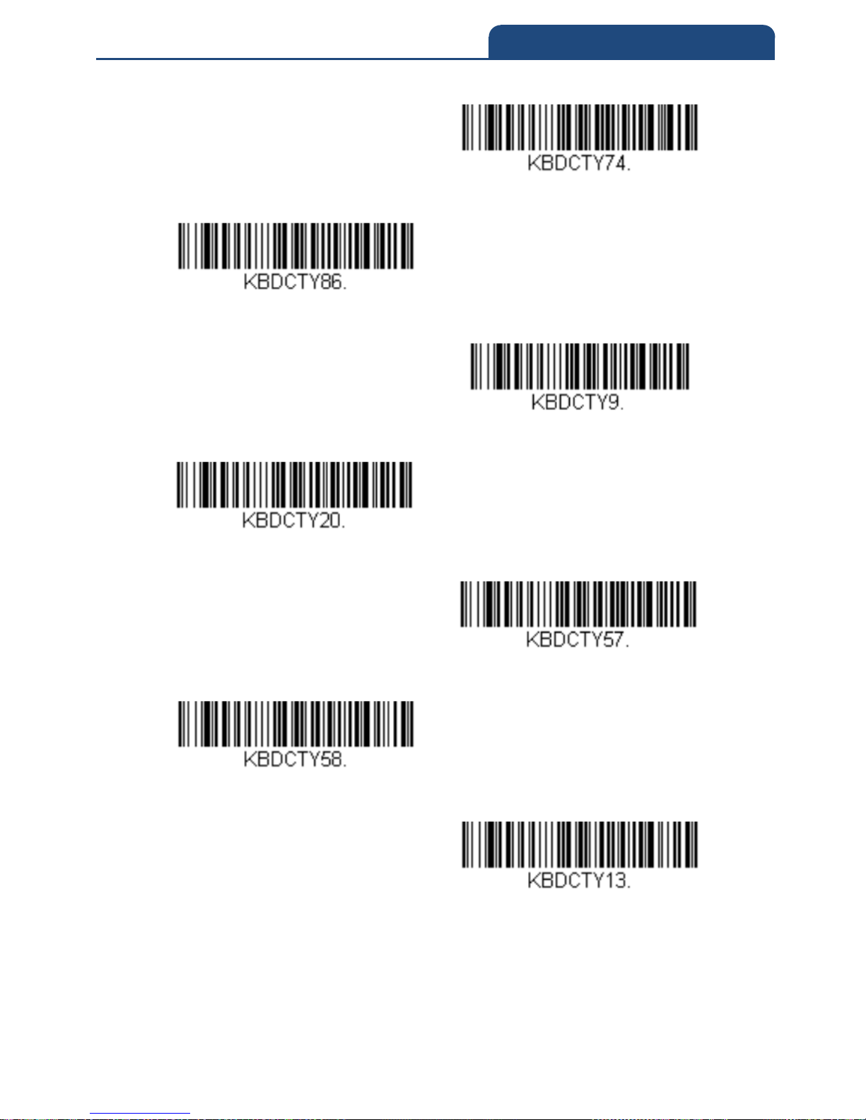
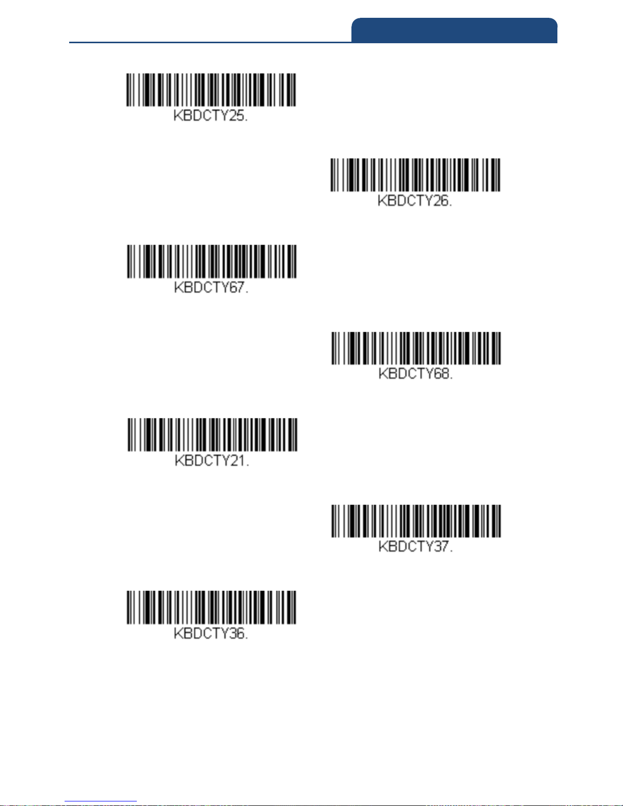
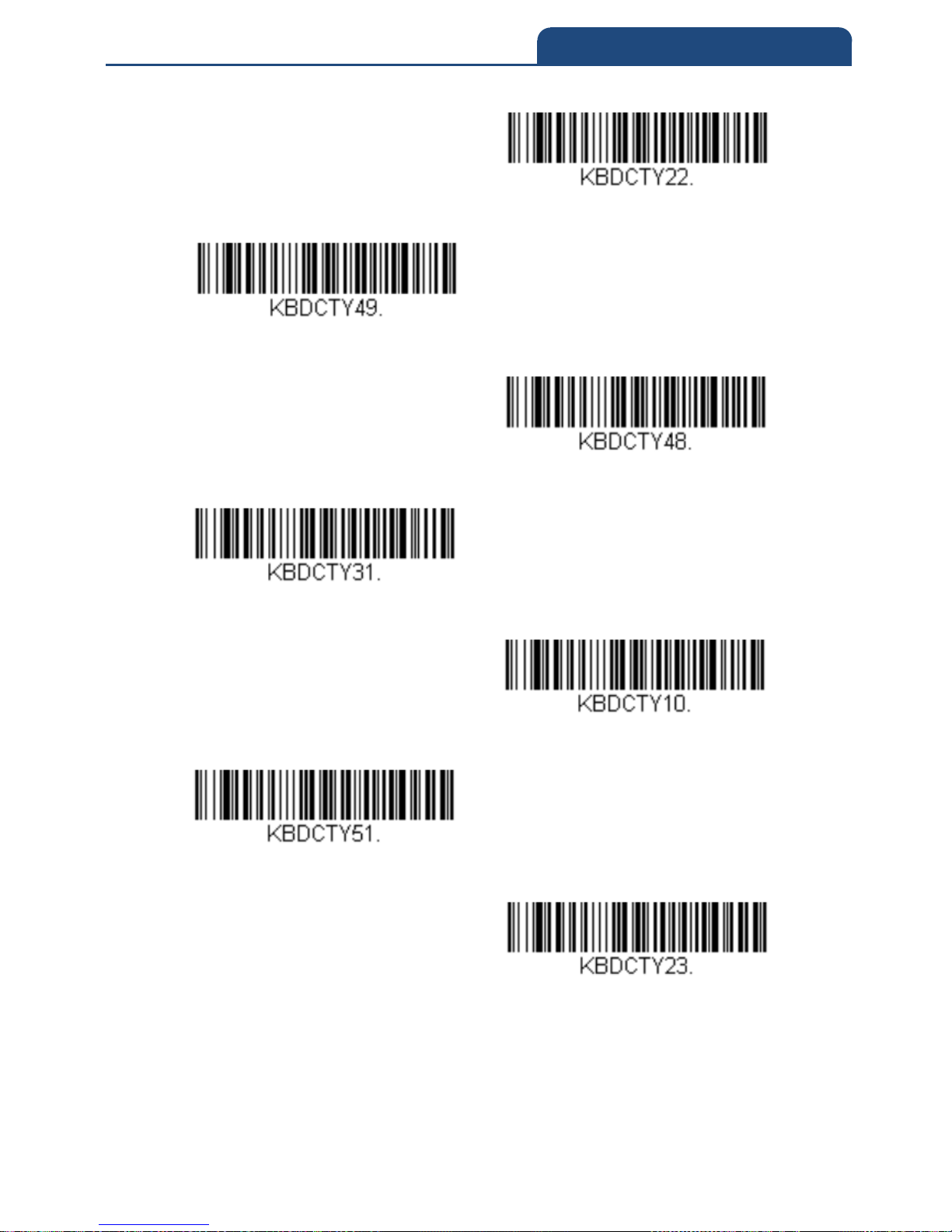
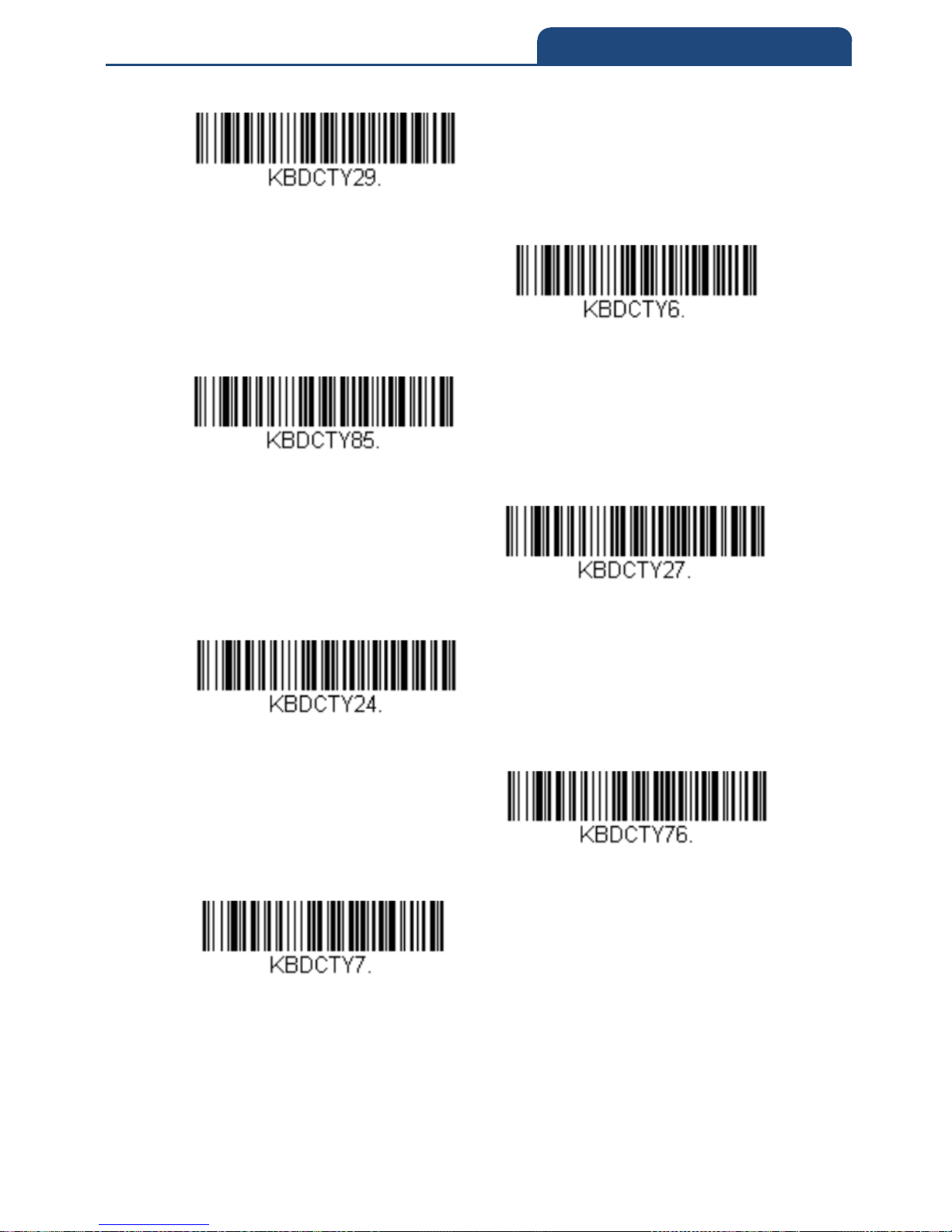
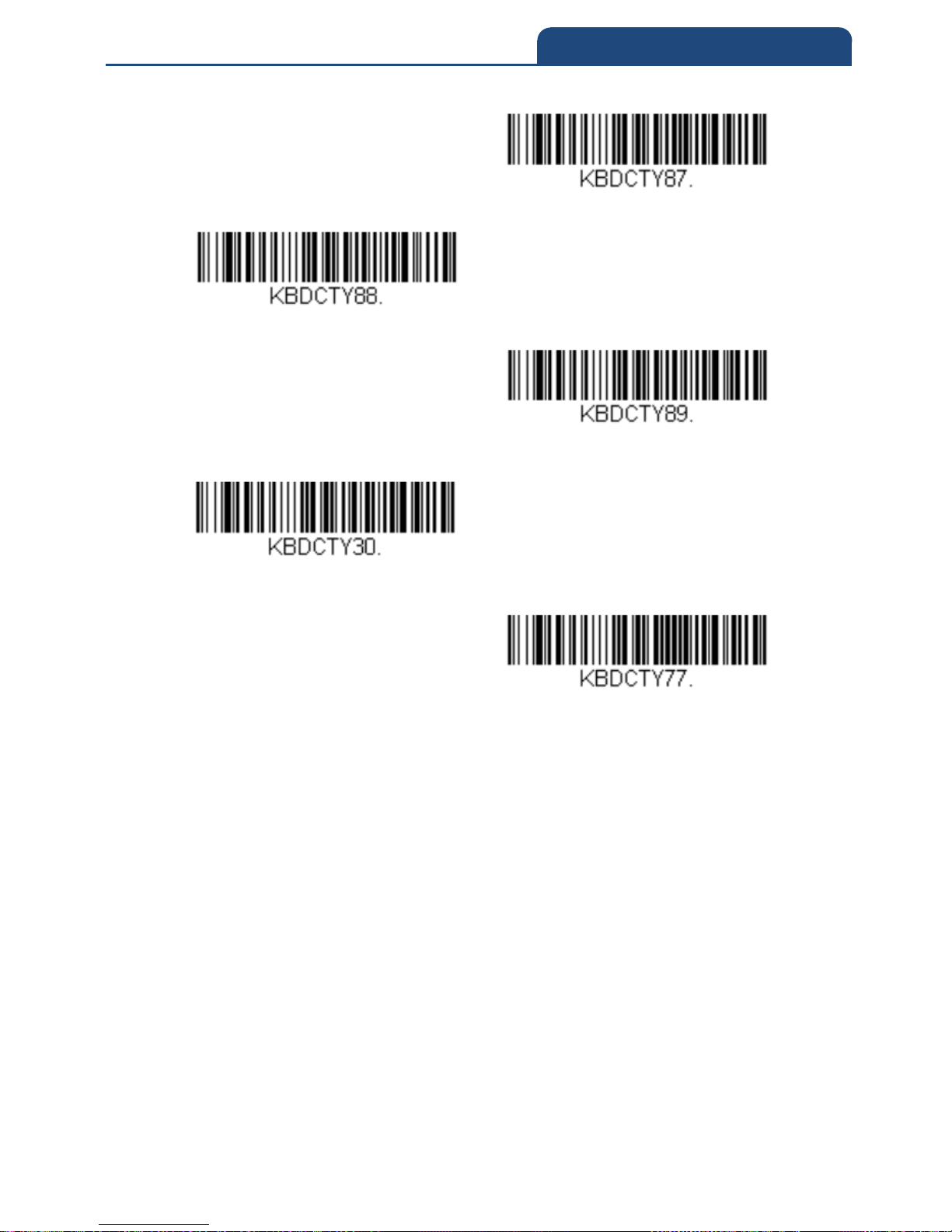
2-3 Keyboard Country Layout
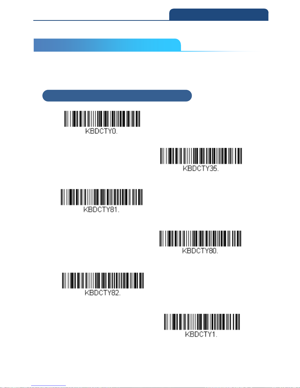
Scan the appropriate country code below to program the keyboard layout for
your country or language. As a general rule, the following characters are
supported, but need special care for countries other than the United States:
@ | $ # { } [ ] = / ‘ \ < > ~
2-3-1 Keyboard Countries
United States
Albania
Azeri (Cyrillic)
Azeri (Latin)
Belarus
Belgium
2-3 Keyboard Country Layout
2-3-1 Keyboard Countries
Page 18
18
2. PROGRAM THE INTERFACE
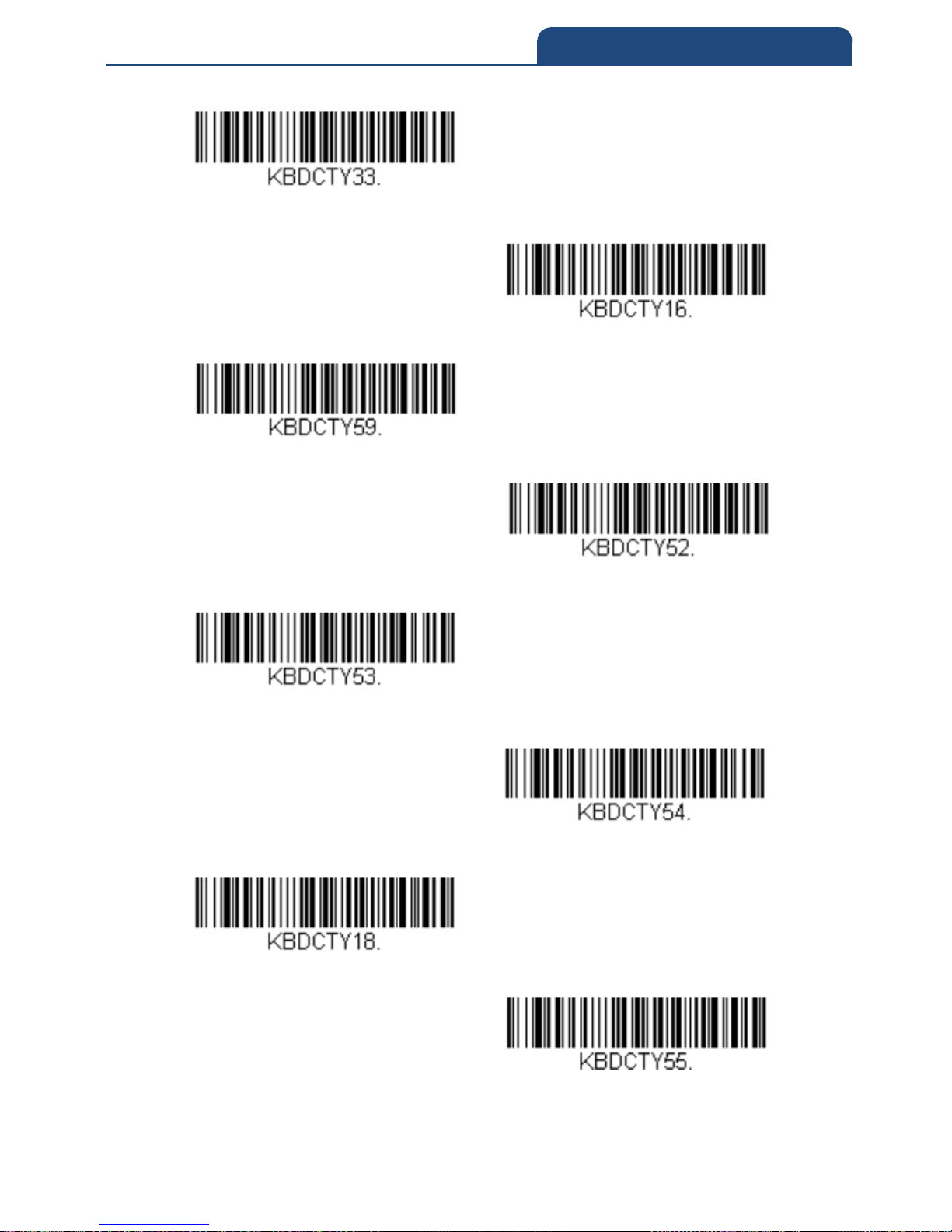
Bosnia
Brazil
Brazil (MS)
Bulgaria (Cyrillic)
Bulgaria (Latin)
Canada (French legacy)
Canada (French)
Canada (Multilingual)
Page 19
19
2. PROGRAM THE INTERFACE
Croatia
Czech
Czech (Programmers)
Czech (QWERTY)
Czech (QWERTZ)
Denmark
Dutch (Netherlands)
Page 20
20
2. PROGRAM THE INTERFACE
Estonia
Faroese
Finland
France
Gaelic
Germany
Greek
Page 21
21
2. PROGRAM THE INTERFACE
Greek (220 Latin)
Greek (220)
Greek (319 Latin)
Greek (319)
Greek (Latin)
Greek (MS)
Greek (Polytonic)
Hebrew
Page 22
22
2. PROGRAM THE INTERFACE
Hungarian (101 key)
Hungary
Iceland
Irish
Italian (142)
Italy
Japan ASCII
Kazakh
Page 23
23
2. PROGRAM THE INTERFACE
Kyrgyz (Cyrillic)
Latin America
Latvia
Latvia (QWERTY)
Lithuania
Lithuania (IBM)
Macedonia
Page 24
24
2. PROGRAM THE INTERFACE
Malta
Mongolian (Cyrillic)
Norway
Poland
Polish (214)
Polish (Programmers)
Portugal
Page 25
25
2. PROGRAM THE INTERFACE
Romania
Russia
Russian (MS)
Russian (Typewriter)
SCS
Serbia (Cyrillic)
Serbia (Latin)
Page 26
26
2. PROGRAM THE INTERFACE
Slovakia
Slovakia (QWERTY)
Slovakia (QWERTZ)
Slovenia
Spain
Spanish variation
Sweden
Page 27
27
2. PROGRAM THE INTERFACE
Switzerland (French)
Switzerland (German)
Tatar
Turkey F
Turkey Q
Ukrainian
United Kingdom
Page 28
28
2. PROGRAM THE INTERFACE
United Stated (Dvorak)
United States (Dvorak left)
United States (Dvorak right)
United States (International)
Uzbek (Cyrillic)
Page 29
29
2. PROGRAM THE INTERFACE
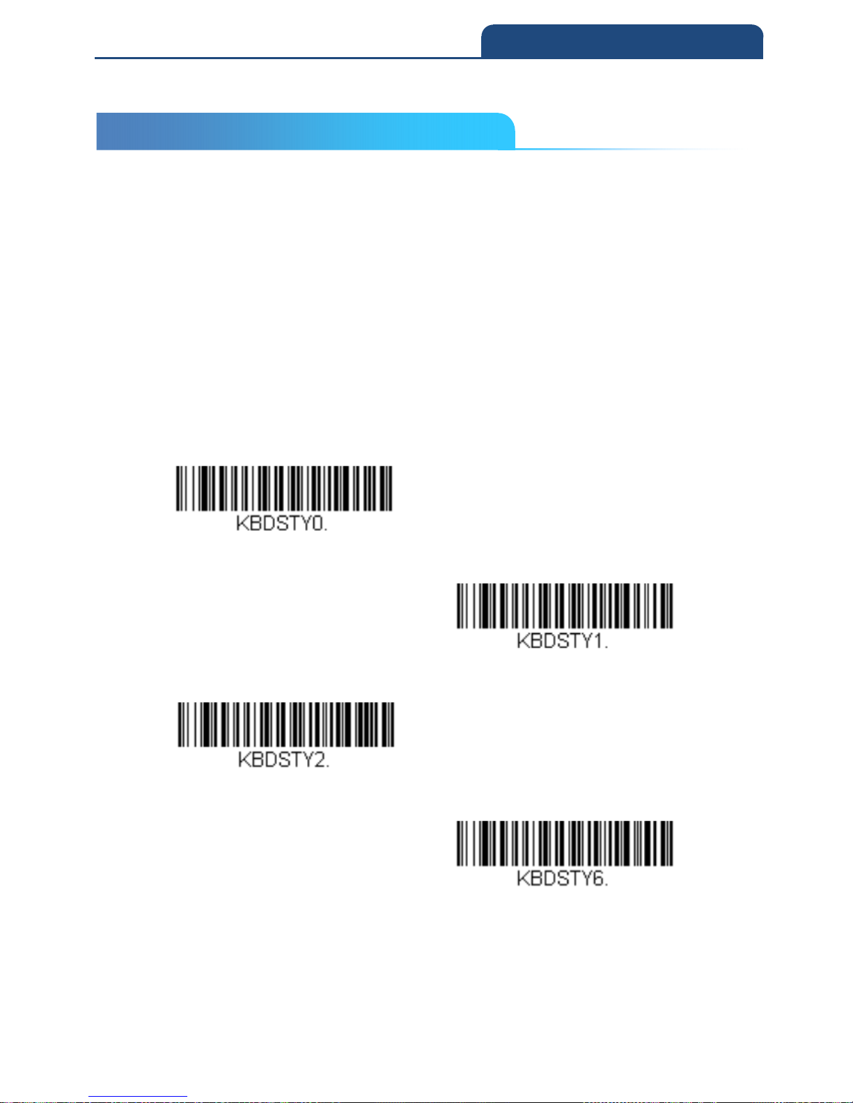
2-4 Keyboard Style
This programs keyboard styles, such as Caps Lock and Shift Lock.
If you have used Keyboard Conversion settings, they will override any of the
following Keyboard Style settings. Default = Regular.
Regular is used when you normally have the Caps Lock key off.
Caps Lock is used when you normally have the Caps Lock key on.
Shift Lock is used when you normally have the Shift Lock key on (not common
to U.S. keyboards)
Automatic Caps Lock is used if you change the Caps Lock key on and off.
The software tracks and reflects if you have Caps Lock on or off. This
selection can only be used with systems that have an LED that notes
the Caps Lock status (AT keyboards).
Regular
Caps Lock
Shift lock
Auto Caps lock
2-4 Keyboard Style
Page 30
30
2. PROGRAM THE INTERFACE
2-5 Keyboard Conversion
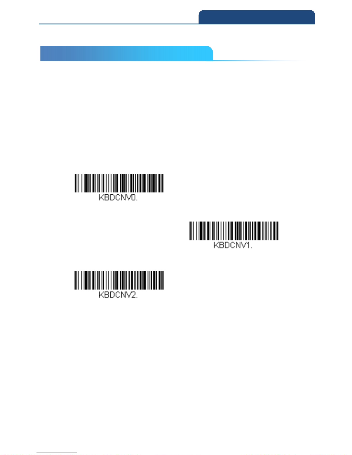
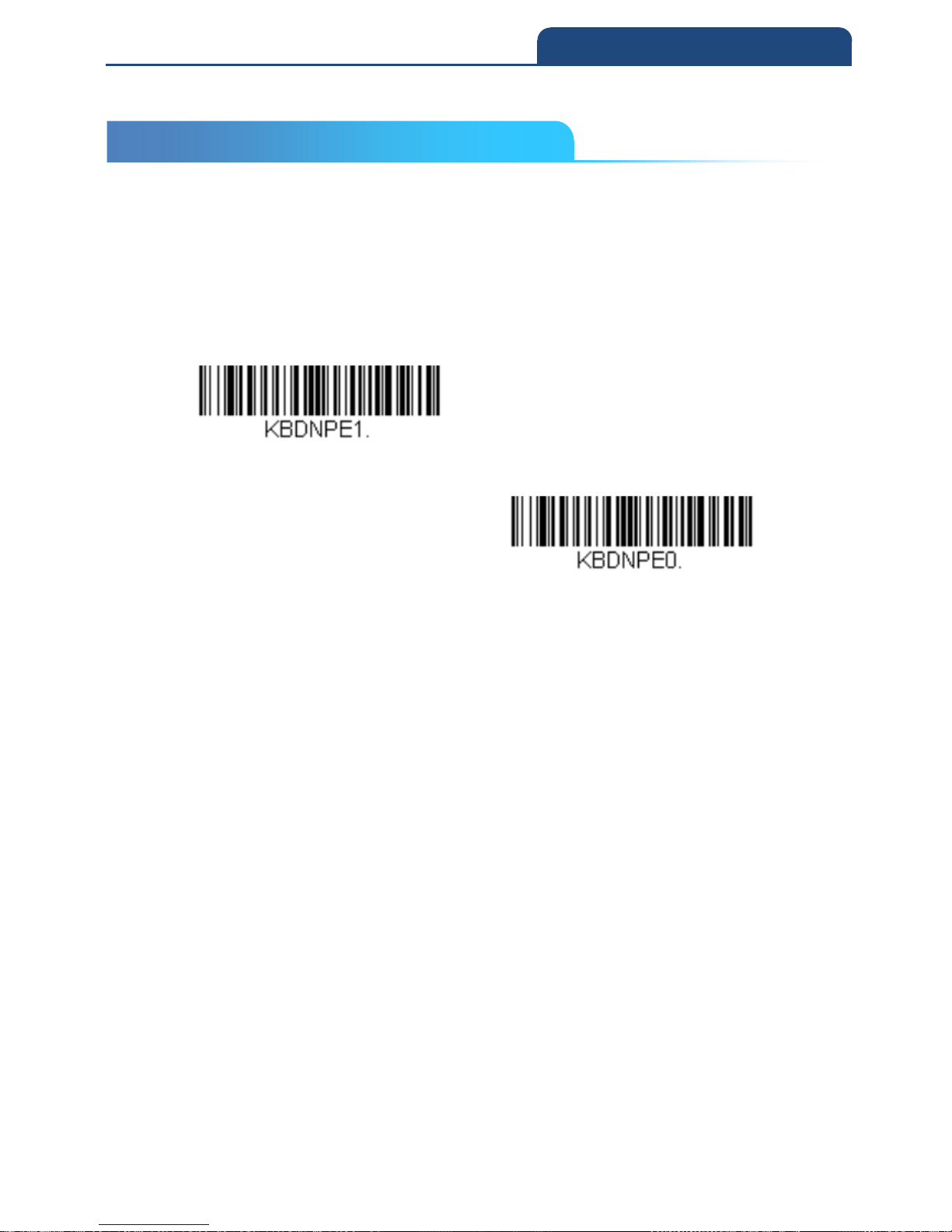
Alphabetic keyboard characters can be forced to be all upper case or all
lowercase.
So if you have the following bar code: “abc569GK,” you can make the output
“ABC569GK” by scanning Convert All Characters to Upper Case, or to
“abc569gk” by scanning Convert All Characters to Lower Case.
These settings override Keyboard Style selections.
Note: If your interface is a keyboard wedge, first scan the menu code for
Automatic Caps Lock. Otherwise, your output may not be as expected.
Default = Keyboard Conversion Off
Keyboard Conversion off
Convert All Characters to Upper Case
Convert All Characters to Lower Case
2-5 Keyboard Conversion
Page 31
31
2. PROGRAM THE INTERFACE
2-6 Control Character Output
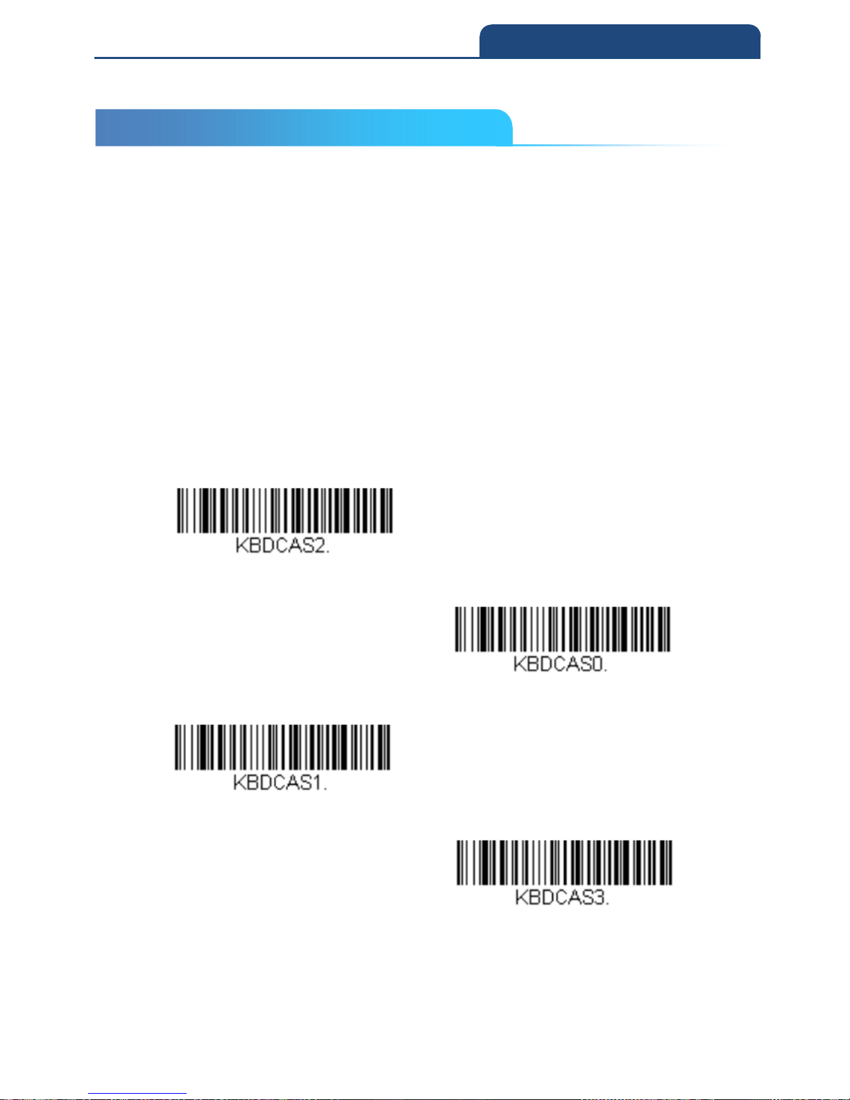
This selection sends a text string instead of a control character. For example,
when the control character for a carriage return is expected, the output would
display [CR] instead of the ASCII code of 0D. Refer to ASCII Conversion Chart
(Code Page 1252). Only codes 00 through 1F are converted (the first column
of the chart).
Note: Control + X (Control + ASCII) Mode overrides this mode.
Control Character Output On
Control Character Output Off
2-6 Control Character Output
Page 32
32
2. PROGRAM THE INTERFACE
2-7 Keyboard Modifiers
This modifies special keyboard features, such as CTRL+ ASCII codes and
Turbo Mode.
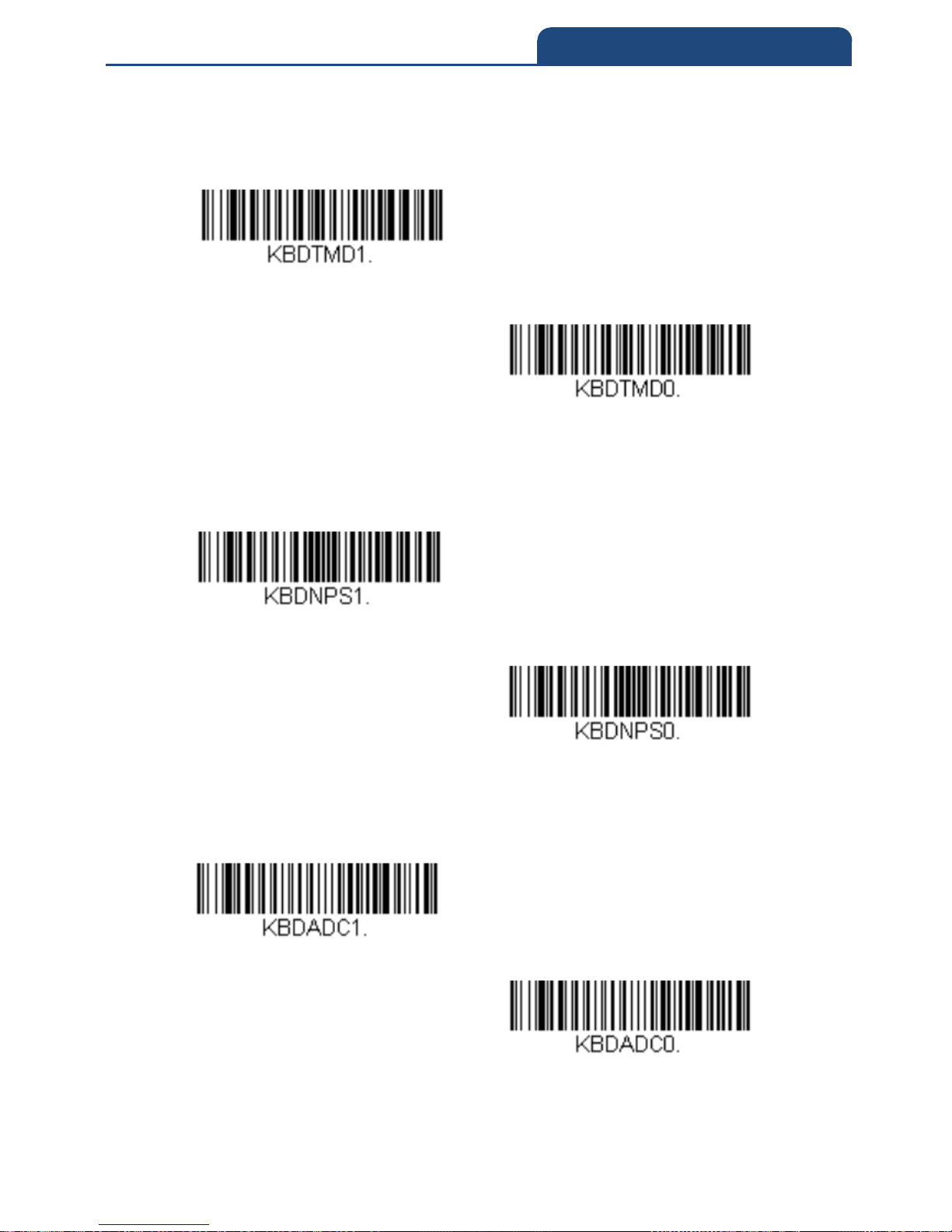
Control + X (Control + ASCII) Mode On: The scan engine sends key
combinations for ASCII control characters for values 00-1F. Windows is the
preferred mode. All keyboard country codes are supported. DOS mode is a
legacy mode, and it does not support all keyboard country codes. New users
should use the Windows mode. Refer to ASCII Conversion Chart (Code Page
1252) for CTRL+ X Values.
Windows Mode Prefix/Suffix Off: The scan engine sends key combinations
for ASCII control characters for values 00-1F, but it does not translate any
prefix or suffix information.
Default = Control + X Mode Off.
Windows Mode Control + X Mode On
Control + X Mode Off
DOS Mode Control + X Mode On
Windows Mode Prefix/Suffix Off
2-7 Keyboard Modifiers
Page 33
33
2. PROGRAM THE INTERFACE
Turbo Mode: The scan engine sends characters to a terminal faster. If the
terminal drops characters, do not use Turbo Mode. Default = Off
Turbo Mode On
Turbo Mode Off
Numeric Keypad Mode: Sends numeric characters as if entered from a
numeric keypad. Default = Off
Numeric Keypad Mode On
Numeric Keypad Mode off
Automatic Direct Connect Mode: This selection can be used if you have an
IBM AT style terminal and the system is dropping characters. Default = Off
Automatic Direct Connect Mode On
Automatic Direct Connect Mode Off
Page 34
34
2. PROGRAM THE INTERFACE
2-8 RS232 Modifiers
2-8-1 Baud Rate
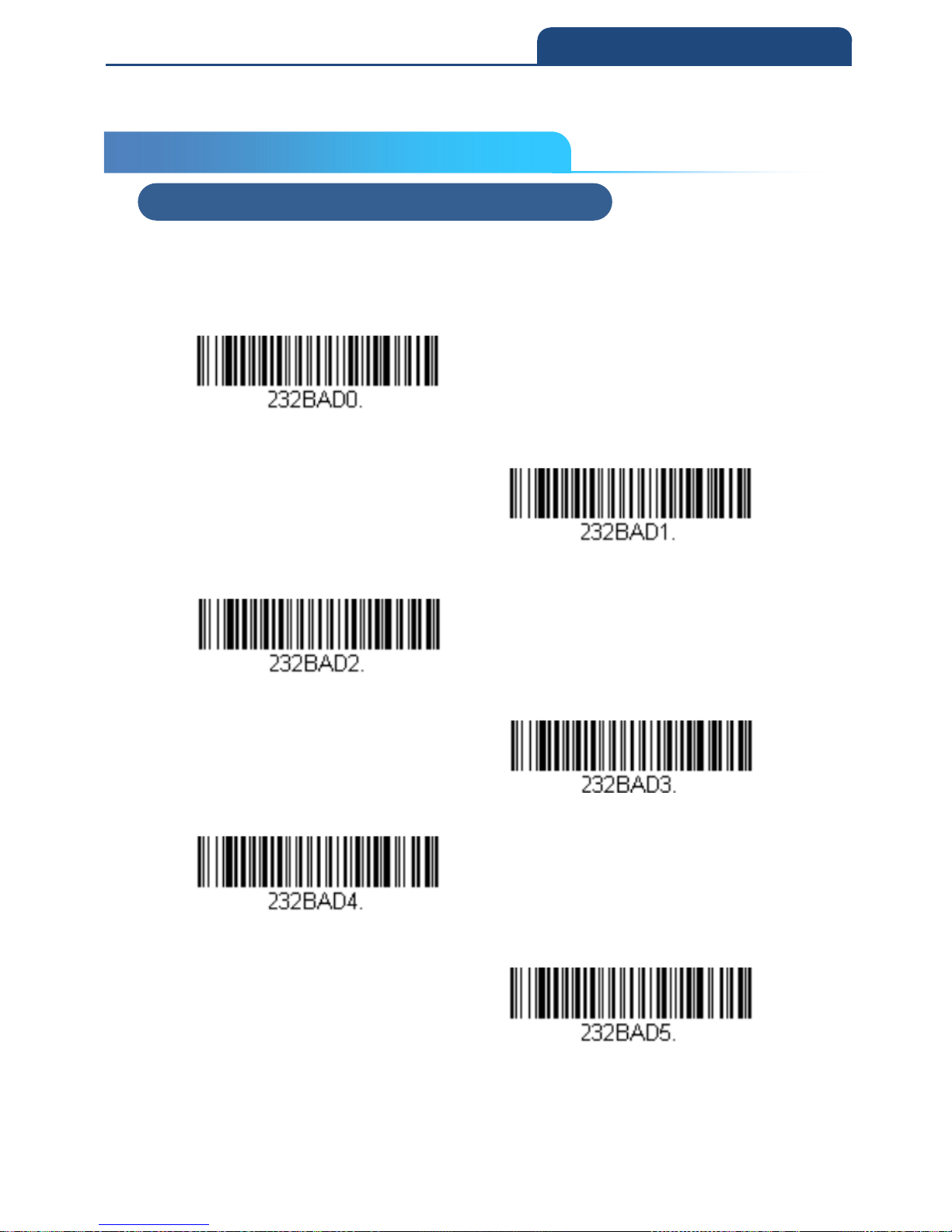
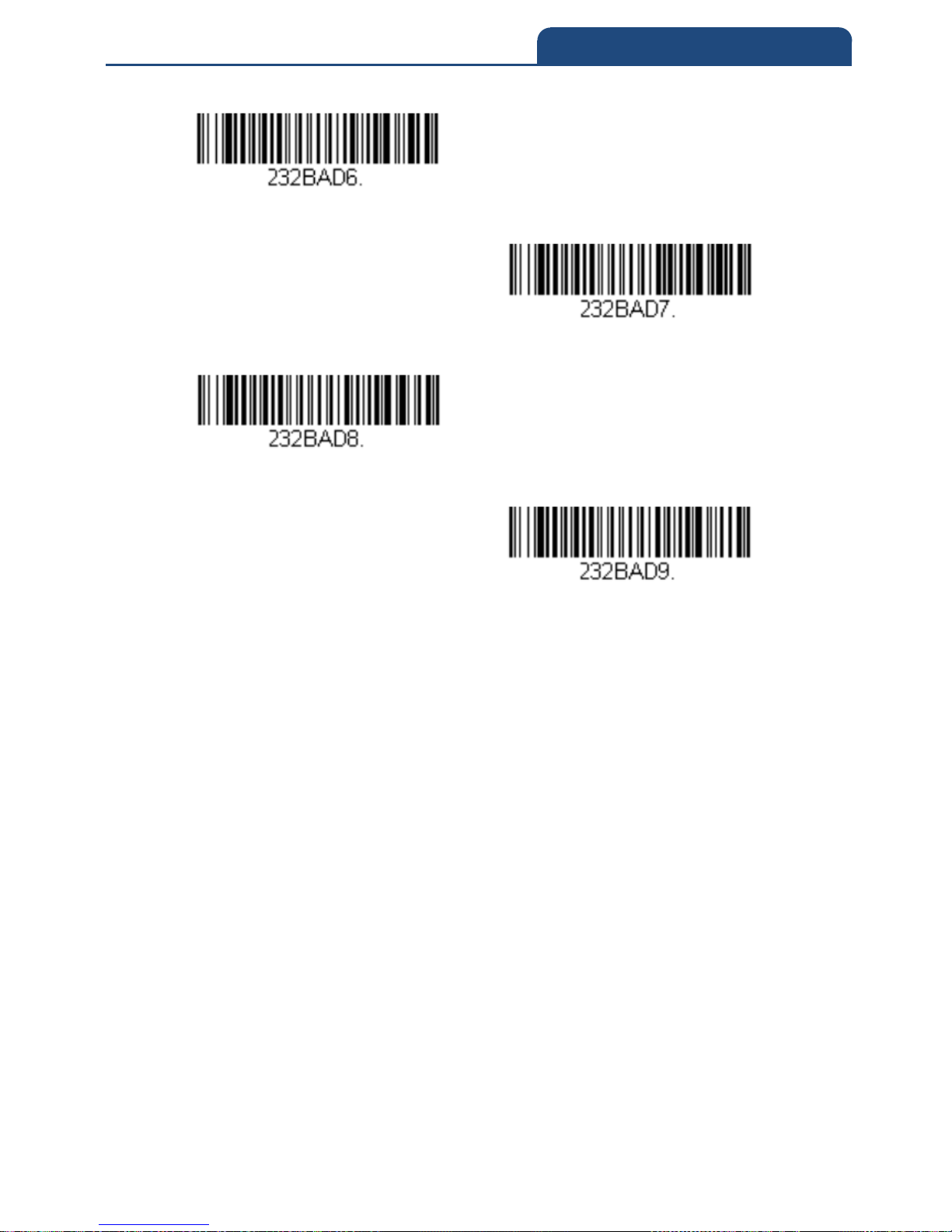
Baud Rate sends the data from the scan engine to the terminal at the specified
rate. The host terminal must be set for the same baud rate as the scan engine.
Default = 115200
300 bps
600 bps
1200 bps
2400 bps
4800 bps
9600 bps
2-8 RS232 Modifiers
2-8-1 Baud Rate
Page 35
35
2. PROGRAM THE INTERFACE
19200 bps
38400 bps
57600 bps
115200 bps
Page 36
36
2. PROGRAM THE INTERFACE
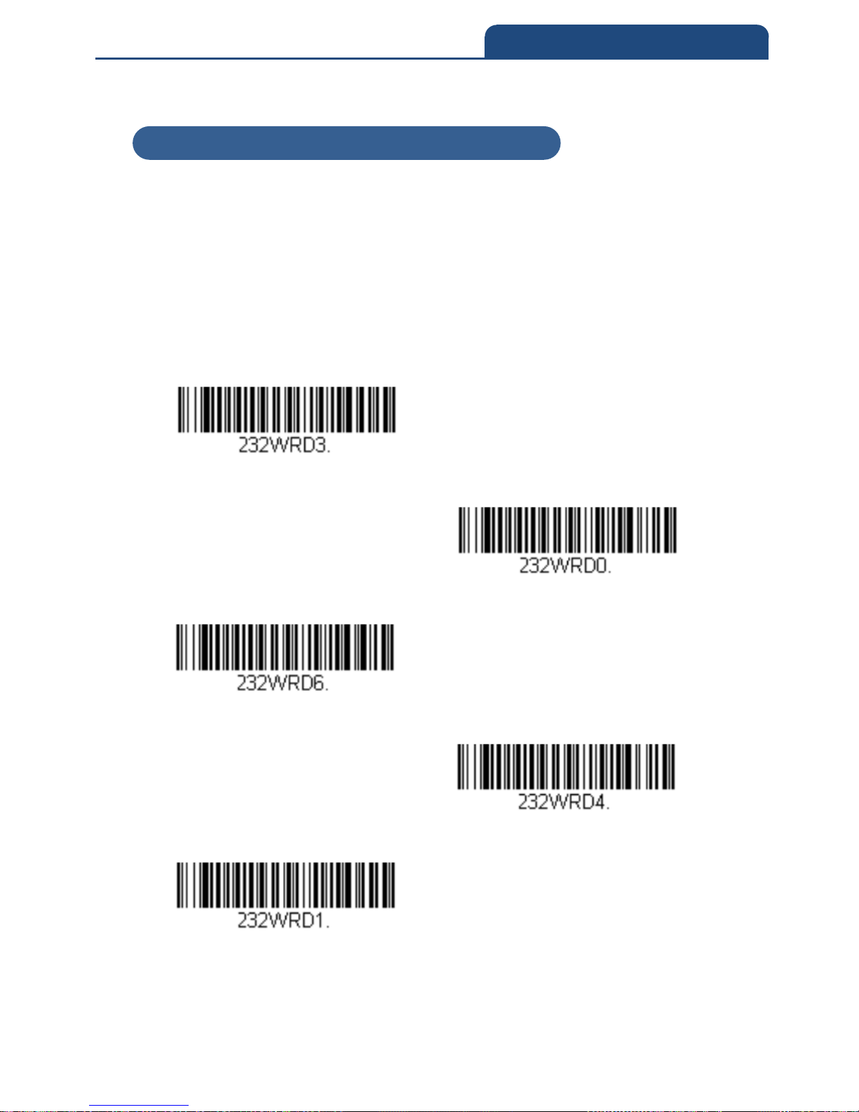
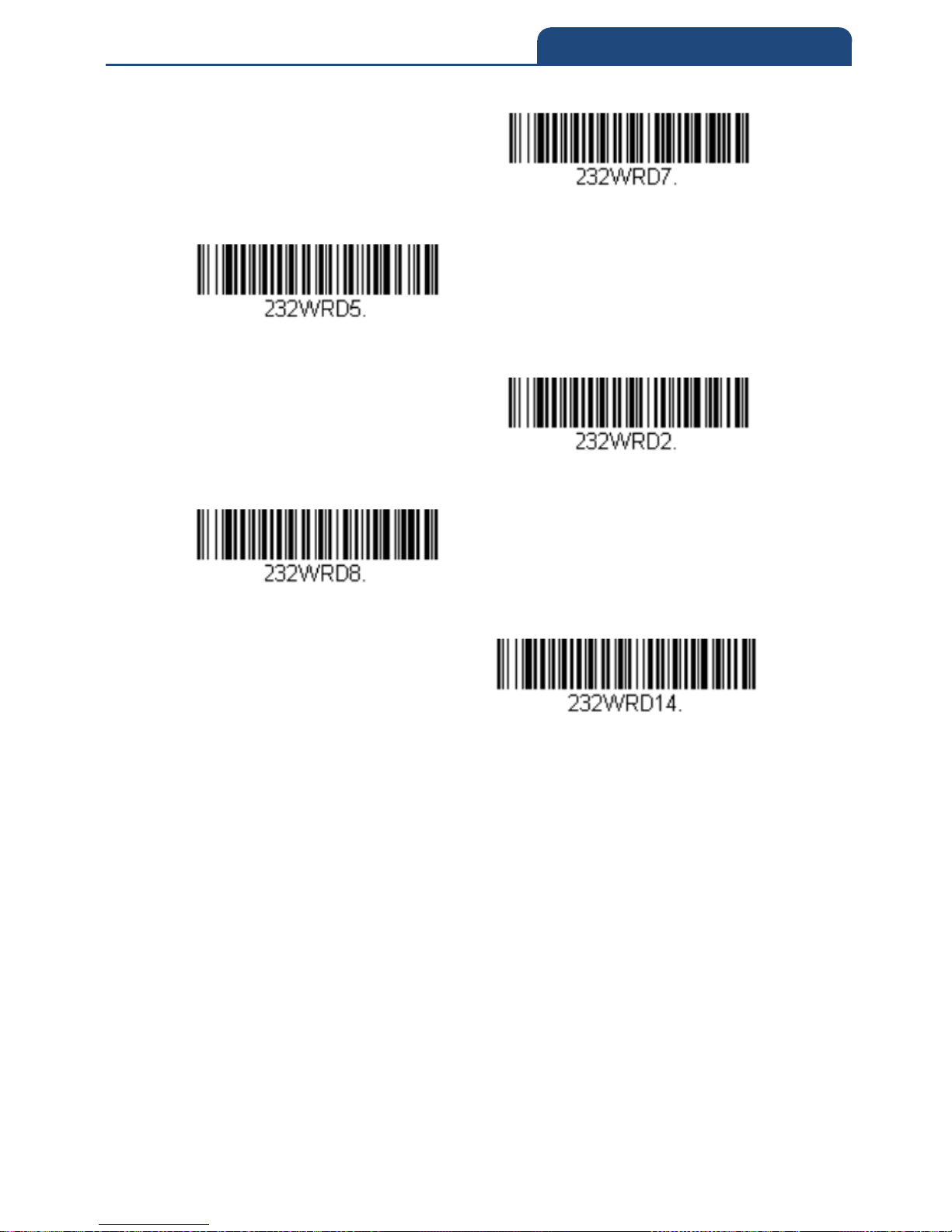
2-8-2 RS232 Word Length Data Bits, Stop Bits, and Parity
Data Bits sets the word length at 7 or 8 bits of data per character. If an
application requires only ASCII Hex characters 0 through 7F decimal (text,
digits, and punctuation), select 7 data bits. For applications that require use of
the full ASCII set, select 8 data bits per character. Default = 8
Stop Bits sets the stop bits at 1 or 2. Default = 1
Parity provides a means of checking character bit patterns for validity.
Default = None
7 data, 1 stop, parity Even
7 data, 1 stop, parity none
7 data, 1 stop, parity odd
7 data, 2 stop, Parity Even
7 data, 2 stop, Parity None
2-8-2 RS232 Word Length Data Bits, Stop Bits, and Parity
Page 37
37
2. PROGRAM THE INTERFACE
7 Data, 2 Stop, Parity Odd
8 Data, 1 Stop, Parity Even
8 Data, 1 Stop, Parity None
8 Data, 1 Stop, Parity Odd
8 Data, 1 Stop, Parity Mark
Page 38

38
2. PROGRAM THE INTERFACE
2-8-3 RS232 Receiver Time-Out
The unit stays awake to receive data until the RS232 Receiver Time-Out
expires. A manual or serial trigger resets the time-out. When an RS232
receiver is sleeping, a character may be sent to wake up the receiver and reset
the time-out. A transaction on the CTS line will also wake up the receiver. The
receiver takes 300 milliseconds to completely come up. Change the RS232
receiver time-out by scanning the bar code below, then scanning digits from
the inside back cover of this manual, then scanning Save. The range is 0 to
300 seconds.
Default = 0 seconds (no time-out - always on)
RS232 Receiver Time-Out
2-8-3 RS232 Receiver Time-Out
Page 39
39
2. PROGRAM THE INTERFACE
2-8-4 RS232 Handshaking
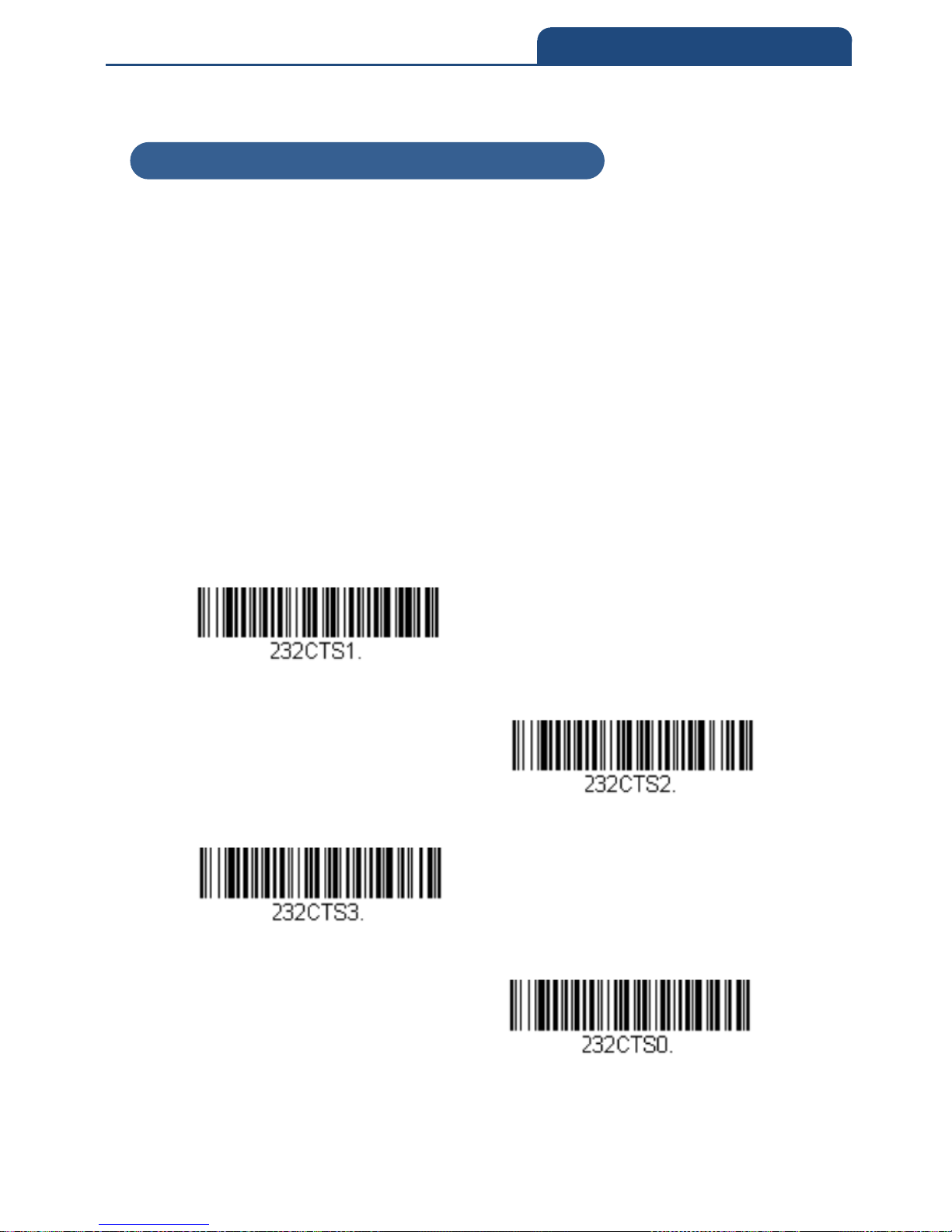
RS232 Handshaking allows control of data transmission from the scan engine
using software commands from the host device. When RTS/CTS is turned Off,
no data flow control is used.
Flow Control, No Timeout: The scan engine asserts RTS when it has data to
send, and will wait indefinitely for CTS to be asserted by the host.
Two-Direction Flow Control: The scan engine asserts RTS when it is OK for
the host to transmit. The host asserts CTS when it is OK for the device to
transmit.
Flow Control with Timeout: The scan engine asserts RTS when it has data to
send and waits for a delay (see RS232 Timeout) for CTS to be asserted by the
host. If the delay time expires and CTS is not asserted, the device transmit
buffer is cleared and scanning may resume.
Default = RTS/CTS Off
Flow Control, No Timeout
Two-Direction Flow Control
Flow Control with Timeout
RTS/CTS Off
2-8-4 RS232 Handshaking
Page 40
40
2. PROGRAM THE INTERFACE
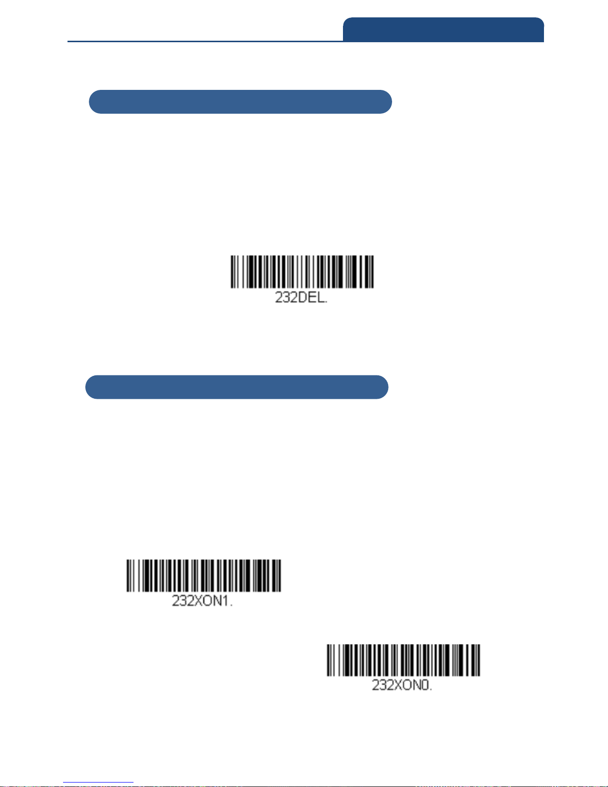
2-8-5 RS232 Timeout
When using Flow Control with Timeout, you must program the length of the
delay you want to wait for CTS from the host. Set the length (in milliseconds)
for a timeout by scanning the bar code below, then setting the timeout (from
1-5100 milliseconds) by scanning digits from the inside back cover, then
scanning Save.
RS232 Timeout
2-8-6 XON/XOFF
Standard ASCII control characters can be used to tell the scan engine to start
sending data (XON/XOFF On) or to stop sending data (XON/XOFF Off). When
the host sends the XOFF character (DC3, hex 13) to the scan engine, data
transmission stops. To resume transmission, the host sends the XON
character (DC1, hex 11). Data transmission continues where it left off when
XOFF was sent.
Default = XON/XOFF Off
XON/XOFF ON
XON/XOFF OFF
2-8-5 RS232 Timeout
2-8-6 XON/XOFF
Page 41
41
2. PROGRAM THE INTERFACE
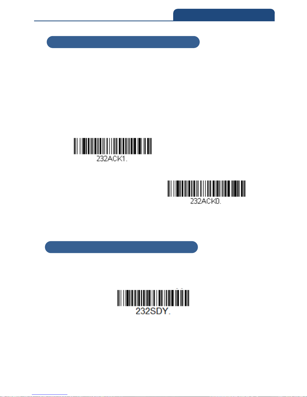
2-8-7 ACK/NAK
After transmitting data, the scan engine waits for an ACK character (hex 06) or
a NAK character (hex 15) response from the host. If ACK is received, the
communications cycle is completed and the scan engine looks for more bar
codes. If NAK is received, the last set of bar code data is retransmitted and the
scan engine waits for ACK/NAK again. Turn on the ACK/NAK protocol by
scanning the ACK/NAK On bar code below. To turn off the protocol, scan
ACK/NAK Off.
Default = ACK/NAK Off
ACK/NAK ON
ACK/NAK OFF
2-8-8 RS232 Stop Mode
Scan the following bar code to force the engine into a stop mode. Restart the
engine by using a trigger pull, nWake, or RxD toggle.
RS232 Stop Mode On
2-8-7 ACK/NAK
2-8-8 RS232 Stop Mode
Page 42

42
3. INPUT/OUTPUT SETTINGS
Chapter 3: INPUT/OUTPUT SETTINGS
3-1 Power Up Beeper
3-2 Beep on BEL Character
3-3 Trigger Click
3-4 Good Read and Error Indicators
3-4-1 Beeper – Good Read
3-4-2 Beeper Volume – Good Read
3-4-3 Beeper Pitch – Good Read
3-4-4 Beeper Pitch – Error
3-4-5 Beeper Duration – Good Read
3-4-6 LED – Good Read
3-4-7 Number of Beeps – Good Read
3-4-8 Number of Beeps – Error
3-4-9 Good Read Delay
3-4-10 User-Specified Good Read Delay
3-5 Manual Trigger Mode
3-5-1 LED Illumination – Manual Trigger
3-6 Character Activation Mode
3-6-1 Activation Character
3-6-2 End Character Activation After Good Read
3-6-3 Character Activation Timeout
3-7 Character Deactivation Mode
3-7-1 Deactivation Character
3-8 Serial Trigger Mode
3-8-1 Read Time-Out
3-9 Presentation Mode
3-9-1 Idle Illumination – Presentation Mode
3-9-2 Presentation Sensitivity
3-9-3 Presentation Centering
3-10 CodeGate
3-11 Mobile Phone Read Mode
3-12 Poor Quality Codes
3-12-1 Poor Quality 1D codes
3-12-2 Poor Quality PDF codes
3-13 Hands Free Time-Out
3-14 Reread Delay
3-15 User-Specified Reread Delay
Page 43

43
3. INPUT/OUTPUT SETTINGS
3-16 2D Reread Delay
3-17 Illumination Lights
3-18 Aimer Delay
3-18-1 User-Specified Aimer Delay
3-19 Aimer Mode
3-20 Centering
3-21 Multiple Symbols
3-22 No Read
3-23 Video Reverse
3-24 Working Orientation
Page 44
44
3. INPUT/OUTPUT SETTINGS
3-1 Power Up Beeper
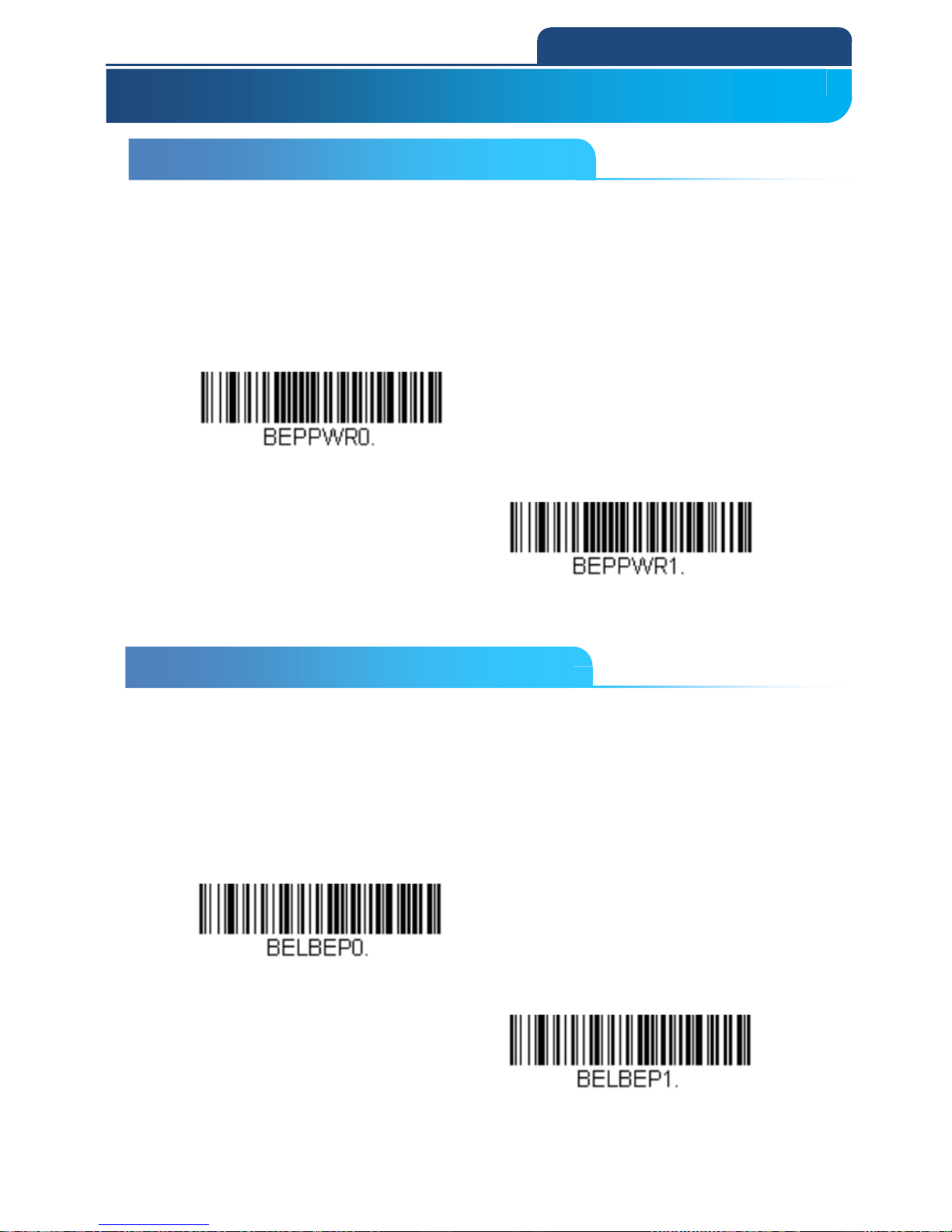
The scan engine can be programmed to beep when it’s powered up.
Scan the Off bar code(s) if you don’t want a power up beep.
Default = Power Up Beeper On Scanner
Power up Beer off scanner
Power up Beer on Scanner
3-2 Beep on BEL Character
You may wish to force the scan engine to beep upon a command sent from the
host. If you scan the Beep on BEL On barcode below, the scan engine will
beep every time a BEL character is received from the host.
Default = Beep on BEL Off
Beep on BEL off
Beep on BEL on
3-1 Power Up Beeper
3. INPUT/OUTPUT SETTINGS
3-2 Beep on BEL Character
Page 45
45
3. INPUT/OUTPUT SETTINGS
3-3 Trigger Click
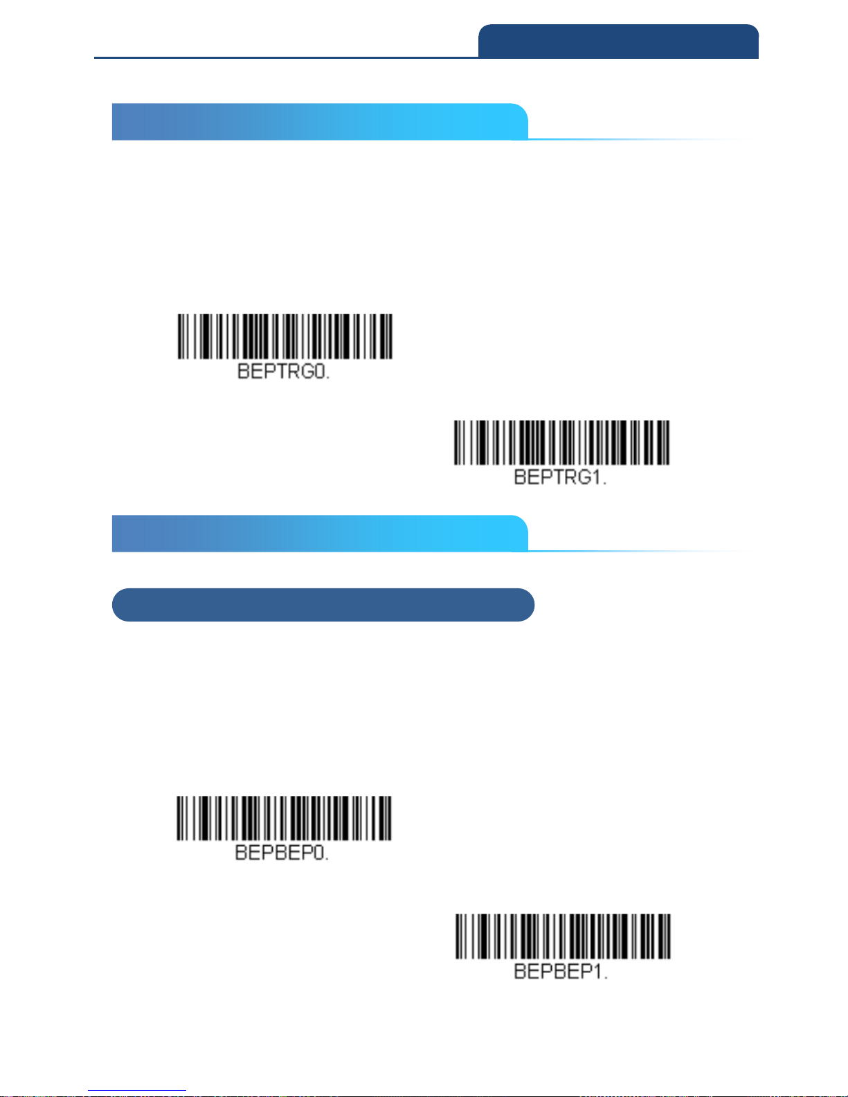
To hear an audible click every time the scanner trigger is pressed, scan the
Trigger Click On bar code below. Scan the Trigger Click Off code if you don’t
wish to hear the click. (This feature has no effect on serial or automatic
triggering.) Default = Trigger Click Off
Trigger Click Off
Trigger Click on
3-4 Good Read and Error Indicators
3-4-1 Beeper – Good Read
The beeper may be programmed On or Off in response to a good read.
Turning this option off only turns off the beeper response to a good read
indication. All error and menu beeps are still audible.
Default = Beeper - Good Read On
Beeper - Good Read Off
Beeper - Good Read On
3-3 Trigger Click
3-4 Good Read and Error Indicators
3-4-1 Beeper – Good Read
Page 46
46
3. INPUT/OUTPUT SETTINGS
3-4-2 Beeper Volume – Good Read
The beeper volume codes modify the volume of the beep the scan engine
emits on a good read.
Default = High
Low
Medium
High
Off
3-4-2 Beeper Volume – Good Read
Page 47
47
3. INPUT/OUTPUT SETTINGS
3-4-3 Beeper Pitch – Good Read
The beeper pitch codes modify the pitch (frequency) of the beep the scan
engine emits on a good read.
Default = Medium
Low (1600 Hz)
Medium (2400 Hz)
High (4200 Hz)
3-4-4 Beeper Pitch – Error
The beeper pitch codes modify the pitch (frequency) of the sound the scan
engine emits when there is a bad read or error.
Default = Razz
Razz (250 Hz)
3-4-3 Beeper Pitch – Good Read
3-4-4 Beeper Pitch – Error
Page 48
48
3. INPUT/OUTPUT SETTINGS
Medium (3250 Hz)
High (4200 Hz)
3-4-5 Beeper Duration – Good Read
The beeper duration codes modify the length of the beep the scan engine
emits on a good read.
Default = Normal
Normal Beep
Short Beep
3-4-5 Beeper Duration – Good Read
Page 49
49
3. INPUT/OUTPUT SETTINGS
3-4-6 LED – Good Read
The LED indicator can be programmed On or Off in response to a good read.
Default = On
LED - Good Read On
LED - Good Read Off
3-4-7 Number of Beeps – Good Read
The number of beeps of a good read can be programmed from 1 - 9. The same
number of beeps will be applied to the beeper and LED in response to a good
read. For example, if you program this option to have five beeps, there will be
five beeps and five LED flashes in response to a good read. The beeps and
LED flashes are in sync with one another. To change the number of beeps,
scan the bar code below and then scan a digit (1-9) bar code and the Save
barcode on the Programming Chart inside the back cover of this manual.
Default = 1
Number of Good Read Beeps/LED Flashes
3-4-6 LED – Good Read
3-4-7 Number of Beeps – Good Read
Page 50
50
3. INPUT/OUTPUT SETTINGS
3-4-8 Number of Beeps – Error
The number of beeps and LED flashes emitted by the scan engine for a bad
read or error can be programmed from 1 - 9. For example, if you program this
option to have five error beeps, there will be five error beeps and five LED
flashes in response to an error. To change the number of error beeps, scan the
bar code below and then scan a digit (1-9) bar code and the Save barcode on
the Programming Chart inside the back cover of this manual.
Default = 1
Number of Error Beeps/LED Flashes
3-4-9 Good Read Delay
This sets the minimum amount of time before the scan engine can read
another bar code.
Default = 0 ms (No Delay)
No Delay
Short delay(500ms)
3-4-8 Number of Beeps – Error
3-4-9 Good Read Delay
Page 51
51
3. INPUT/OUTPUT SETTINGS
Medium delay(1,000ms)
Long delay,(1,500ms)
3-4-10 User-Specified Good Read Delay
If you want to set your own length for the good read delay, scan the bar code
below, then set the delay (from 0-30,000 milliseconds) by scanning digits from
the inside back cover, then scanning Save.
User-Specified Good Read Delay
Example) When setting the delay time to 10 seconds, scan in the following
order.
「User-Specified Good Read Delay」→「1」「0」「0」「0」「0」→「Save」
3-4-10 User-Specified Good Read Delay
Page 52
52
3. INPUT/OUTPUT SETTINGS
3-5 Manual Trigger Mode
When in manual trigger mode, the scanner scans until a bar code is read, or
until the trigger is released.
Manual Trigger - Normal
3-5-1 LED Illumination - Manual Trigger
If you wish to set the illumination LED brightness, scan one of the barcodes
below. This sets the LED illumination for the scan engine when the trigger is
pressed.
Default = High
Note: The LEDs are like a flash on a camera. The lower the ambient light in the
room, the brighter the LEDs need to be so the scan engine can “see” the bar
codes.
Low
High
3-5 Manual Trigger Mode
3-5-1 Illumination – Manual Trigger
Page 53
53
3. INPUT/OUTPUT SETTINGS
3-6 Character Activation Mode
You may use a character sent from the host to trigger the scanner to begin
scanning. When the activation character is received, the scanner continues
scanning until either the Character Activation Timeout, the deactivation
character is received (see Deactivation Character), or a bar code is transmitted.
Scan the following On bar code to use character activation, then use Activation
Character (following) to select the character you will send from the host to start
scanning.
Default = Off
Off
On
3-6-1 Activation Character
This sets the character used to trigger scanning when using Character
Activation Mode. On the ASCII Conversion Chart (Code Page 1252), find the
hex value that represents the character you want to use to trigger scanning.
Scan the following bar code, then use the Programming Chart to read the
alphanumeric combination that represents that ASCII character. Scan Save to
finish.
Default = 12 [DC2]
Activation Character
3-6 Character Activation Mode
3-6-1 Activation Character
Page 54
54
3. INPUT/OUTPUT SETTINGS
3-6-2 End Character Activation After Good Read
After a bar code is successfully detected and read from the scanner, the
illumination can be programmed either to remain on and scanning, or to turn
off. When End Character Activation After Good Read is enabled, the
illumination turns off and stops scanning after a good read. If you scan Do Not
End Character Activation After Good Read, the illumination remains on after a
good read.
Default = Do Not End Character Activation After Good Read
Do Not End Character
Activation After Good Read
End Character Activation After
Good Read
3-6-3 Character Activation Timeout
You can set a timeout for the length of time the illumination remains on and
attempting to decode bar codes when using Character Activation Mode. Set
the length (in milliseconds) for a timeout by scanning the following bar code,
then setting the timeout (from 1-300,000 milliseconds) by scanning digits from
the Programming Chart inside the back cover of this manual, then scanning
Save.
Default = 30,000 ms
Character Activation Timeout
3-6-2 End Character Activation After Good Read
3-6-3 End Character Activation Timeout
Page 55
55
3. INPUT/OUTPUT SETTINGS
3-7 Character Deactivation Mode
If you have sent a character from the host to trigger the scanner to begin
scanning, you can also send a deactivation character to stop scanning. Scan
the following On bar code to use character deactivation, then use Deactivation
Character (following) to select the character you will send from the host to
terminate scanning.
Default = Off
Off
On
3-7-1 Deactivation Character
This sets the character used to terminate scanning when using Character
Deactivation Mode. On the ASCII Conversion Chart (Code Page 1252), find
the hex value that represents the character you want to use to terminate
scanning. Scan the following bar code, then use the Programming Chart inside
the back cover of this manual to read the alphanumeric combination that
represents that ASCII character. Scan Save to finish.
Default = 14 [DC4]
Deactivation Character
3-7 Character Deactivation Mode
3-7-1 Deactivation Character
Page 56
56
3. INPUT/OUTPUT SETTINGS
3-8 Serial Trigger Mode
You can activate the scan engine either by pressing the trigger, or using a
serial trigger command (see Trigger Commands). When in serial mode, the
scan engine scans until a bar code has been read or until the deactivate
command is sent. The scan engine can also be set to turn itself off after a
specified time has elapsed (see Read Time-Out, which follows).
3-8-1 Read Time-Out
Use this selection to set a time-out (in milliseconds) of the scan engine’s trigger
when using serial commands to trigger the scan engine. Once the scan engine
has timed out, you can activate the scan engine either by pressing the trigger
or using a serial trigger command. After scanning the Read Time-Out bar
code, set the time-out duration (from 0-300,000 millisec- onds) by scanning
digits on the Programming Chart inside the back cover, then scanning Save.
Default = 30,000 ms
Read Time-Out
Example) When setting to 1 second, scan in the following order.
「
Read timeout」→「1」「0」「0」「0」→「Save」
3-8 Serial Trigger Mode
3-8-1 Read Time-Out
Page 57
57
3. INPUT/OUTPUT SETTINGS
3-9 Presentation Mode
Presentation Mode uses ambient light to detect bar codes. The LED dims until
a bar code is presented to the scanner, then the LED brightens to read the
code. If the light level in the room is not high enough, Presentation Mode may
not work properly.
Note: Scan the following bar code to program your scanner for Presentation
Mode.
Presentation Mode
3-9-1 Idle Illumination - Presentation Mode
Scan one of the bar codes below to set the LED illumination for the scanner
when it is in an idle state in Presentation Mode.
Default = On
Note: If you use one of the lower Idle Illumination settings, and there is not
enough ambient light, the scanner may have difficulty detecting when a bar
code is presented to it. If the scanner has difficulty “waking up” to read bar
codes, you may need to set the Idle Illumination to a brighter setting.
Off
On
Note: LED Illumination - Presentation Mode does not apply to Poor Quality
PDF Codes
or Mobile Phone Read Mode.
3-9 Presentation Mode
3-9-1 Idle Illumination – Presentation Mode
Page 58

58
3. INPUT/OUTPUT SETTINGS
3-9-2 Presentation Sensitivity
Presentation Sensitivity is a numeric range that increases or decreases the
scan engine's reaction time to bar code presentation. To set the sensitivity,
scan the Sensitivity bar code, then scan the degree of sensitivity (from 0-20)
from the inside back cover, and Save. 0 is the most sensitive setting, and 20 is
the least sensitive.
Default = 1
Sensitivity
Example) When setting the highest sensitivity 0, scan in the following order.
「Code detection Sensitivity」→「0」→「Save」
3-9-2 Presentation Sensitivity
Page 59
59
3. INPUT/OUTPUT SETTINGS
3-9-3 Presentation Centering
Use Presentation Centering to narrow the scanner’s field of view when it is in
the stand to make sure the scanner reads only those barcodes intended by the
user. For instance, if multiple codes are placed closely together, Presentation
Centering will insure that only the desired codes are read.
Note: To adjust centering when the scanner is hand-held, see Centering If a
barcode is not touched by a predefined window, it will not be decoded or output
by the scanner. If Presentation Centering is turned on by scanning
Presentation Centering On, the scanner only reads codes that pass through
the centering window you specify using the Top of Presentation Centering
Window, Bottom of Presentation Centering Window, Left, and Right of
Presentation Centering Window barcodes.
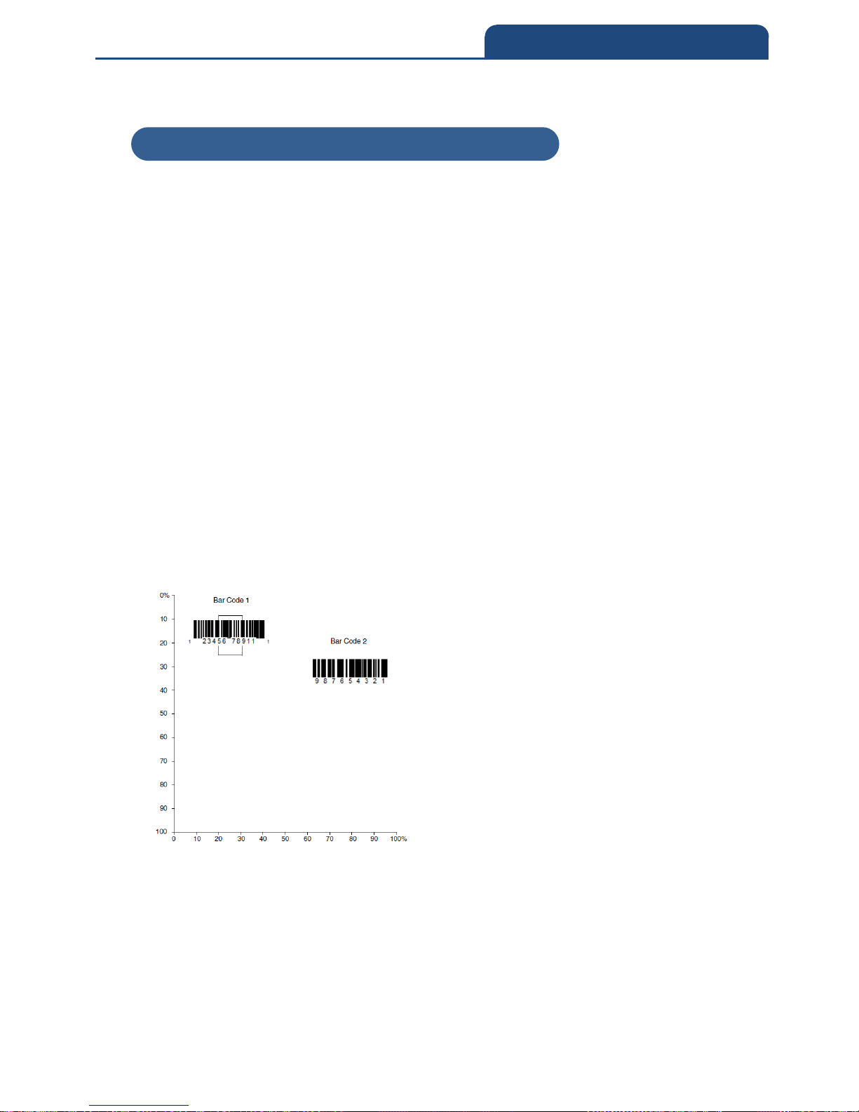
In the example below, the white box is the centering window. The centering
window has been set to 20% left, 30% right, 8% top, and 25% bottom. Since
Bar Code 1 passes through the centering window, it will be read. Bar Code 2
does not pass through the centering window, so it will not be read.
A barcode needs only to be touched by the centering window in order to be
read. It does not need to pass completely through the centering window.Scan
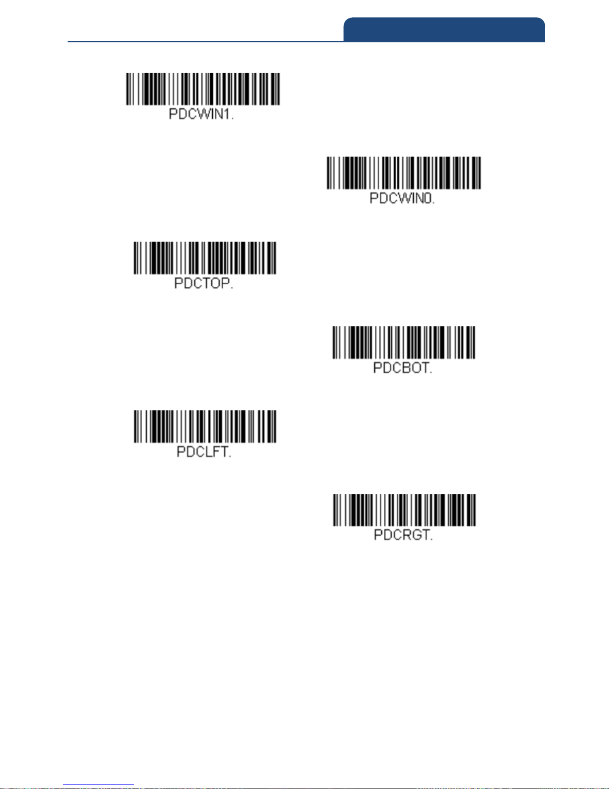
Centering On, then scan one of the following barcodes to change the top and
bottom of the centering window. Then scan the percent you want to shift the
centering window using digits on the inside back cover of this manual. Scan
Save. Default Centering = 40% for Top, 60% for Bottom.
3-9-3 Presentation Centering
Page 60
60
3. INPUT/OUTPUT SETTINGS
With Presentation Centering
Presentation centering Off
Top of Presentation Centering Window
Bottom of Presentation Centering Window
Left of Presentation Centering Window
Right of Presentation Centering Window
Page 61
61
3. INPUT/OUTPUT SETTINGS
3-10 CodeGate
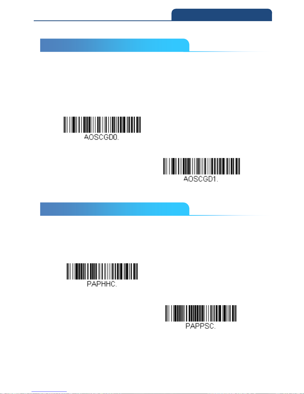
When CodeGate is On, the trigger is used to allow decoded data to be
transmitted to the host system. The scanner remains on, scanning and
decoding bar codes, but the bar code data is not transmitted until the trigger is
pressed. When CodeGate is Off, bar code data is transmitted when it is
decoded.
Default = CodeGate Off Out-ofStand
CodeGate Off Out-of-Stand
CodeGate On Out-of-Stand
3-11 Mobile Phone Read Mode
When this mode is selected, your scanner is optimized to read bar codes from
mobile phone or other LED displays. However, the speed of scanning printed
bar codes may be slightly lower when this mode is enabled.
Hand Held Scanning – Mobile Phone
Presentation Scanning - Mobile Phone
Note: To turn off Mobile Phone Read Mode, scan a Manual or Serial Trigger
3-10 CodeGate
3-11 Mobile Phone Read Mode
Page 62
62
3. INPUT/OUTPUT SETTINGS
Mode bar code
3-12 Poor Quality Codes
3-12-1 Poor Quality 1D codes
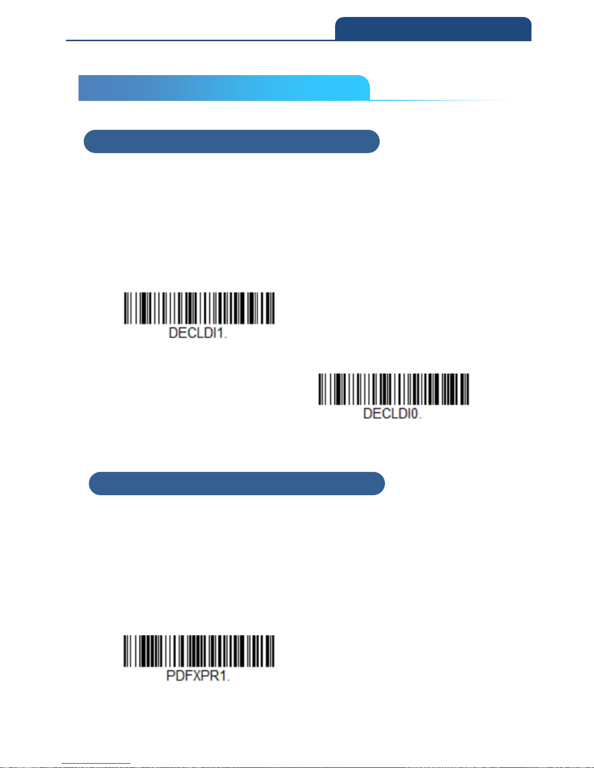
This setting improves the scanner’s ability to read damaged or badly printed
linear bar codes. When Poor Quality 1D Reading On is scanned, poor quality
linear bar code reading is improved, but the scanner’s snappiness is
decreased, making it less aggressive when reading good quality bar codes.
This setting does not affect 2D bar code reading.
Default = Poor Quality 1D Reading Off
Poor quality 1D reading on
Poor quality 1D reading off
3-12-2 Poor Quality PDF Codes
This setting improves the scanner’s ability to read damaged or badly printed
PDF codes by combining information from multiple images. When Poor Quality
PDF On is scanned, poor quality PDF code reading is improved, but the
scanner’s snappiness is decreased, making it less aggressive when reading
good quality bar codes. This setting does not affect 1D bar code reading.
Default = Poor Quality PDF Reading Off
Poor Quality PDF Reading On
3-12 Poor Quality Codes
3-12-1 Poor Quality 1D codes
3-12-2 Poor Quality PDF codes
Page 63
63
3. INPUT/OUTPUT SETTINGS
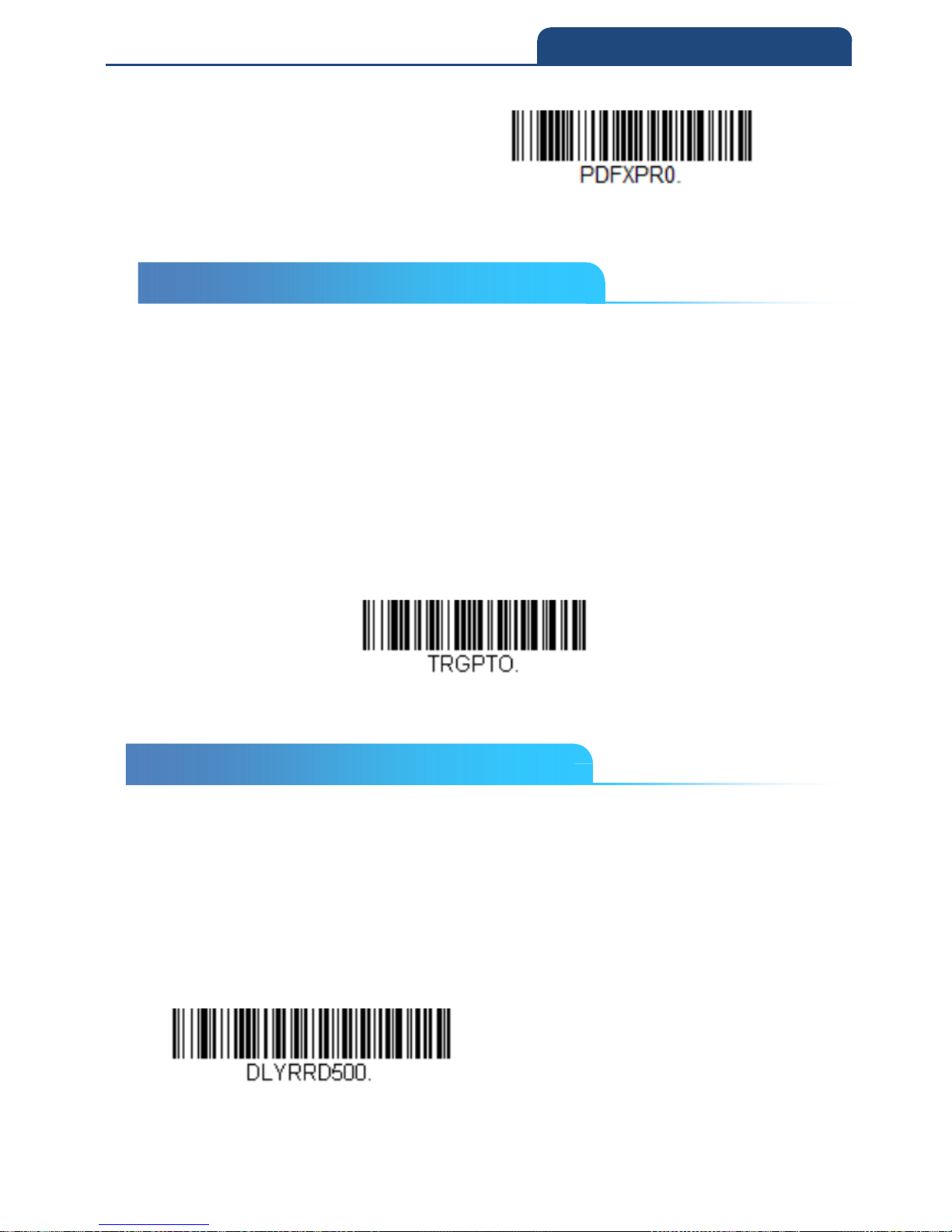
Poor Quality PDF Reading Off
3-13 Hands Free Time-Out
The Scan Stand and Presentation Modes are referred to as “hands free”
modes. If the scanner’s trigger is pulled when using a hands free mode, the
scanner changes to manual trigger mode. You can set the time the scanner
should remain in manual trigger mode by setting the Hands Free Time-Out.
Once the time-out value is reached, (if there have been no further trigger pulls)
the scanner reverts to the original hands free mode.
Scan the Hands Free Time-Out bar code, then scan the time-out duration
(from 0-300,000 milliseconds) from the inside back cover, and Save.
Default = 5,000 ms
Hand Free Time Out
3-14 Reread Delay in Presentation Mode
This sets the time period before the scan engine can read the same bar code a
second time. Setting a reread delay protects against accidental rereads of the
same bar code. Longer delays are effective in minimizing accidental rereads.
Use shorter delays in applications where repetitive bar code scanning is
required. Reread Delay only works when in a Presentation Mode.
Default = Medium
Short(500ms)
3-13 Hands Free Time-Out
3-14 Reread Delay in Presentation Mode
Page 64
64
3. INPUT/OUTPUT SETTINGS
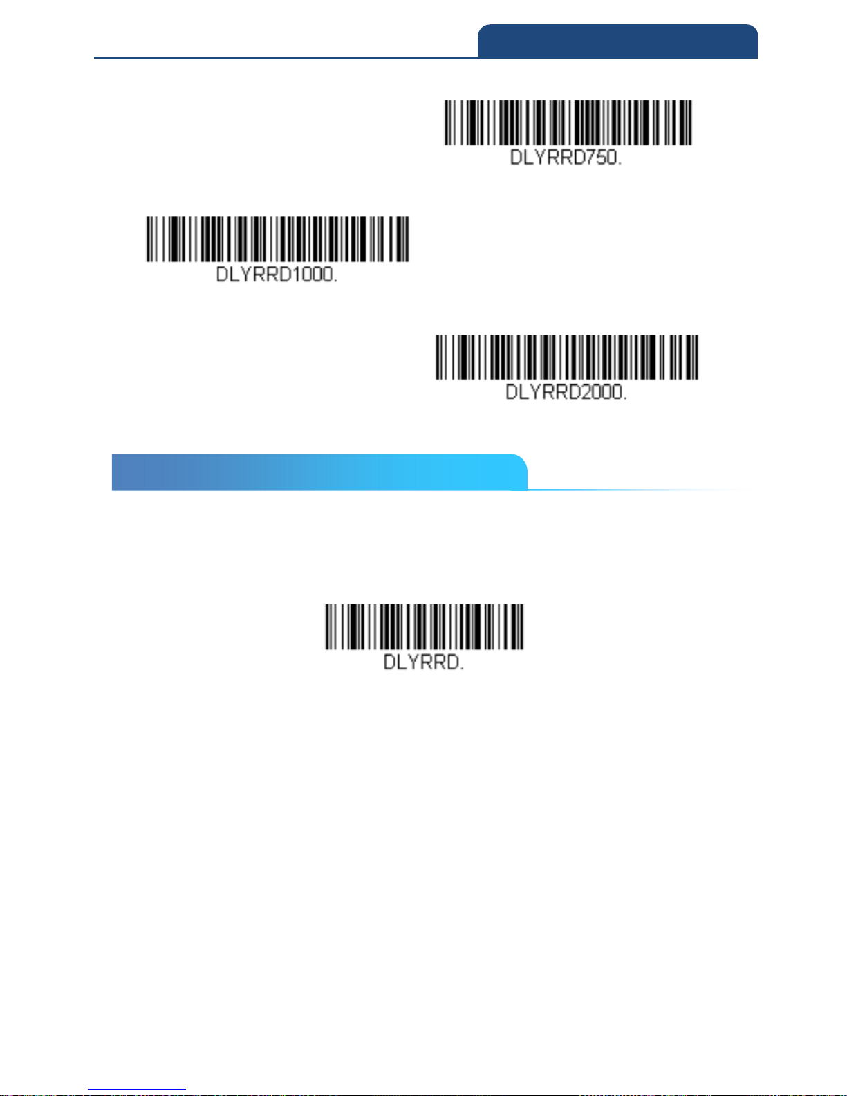
Medium(750ms)
Long(1000ms)
Extra Long(2000ms)
3-15 User-Specified Reread Delay
If you want to set your own length for the reread delay, scan the bar code
below, then set the delay (from 0-30,000 milliseconds) by scanning digits from
the inside back cover, then scanning Save.
User Specified Reread Delay
3-15 User-Specified Reread Delay
Page 65
65
3. INPUT/OUTPUT SETTINGS
3-16 2D Reread Delay
Sometimes 2D bar codes can take longer to read than other bar codes. If you
wish to set a separate Reread Delay for 2D bar codes, scan one of the
programming codes that follows. 2D Reread Delay Off indicates that the time
set for Reread Delay is used for both 1D and 2D bar codes.
Default = 2D Reread Delay Off
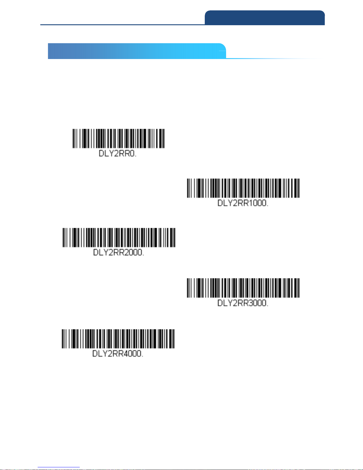
2D Reread Delay Off
Short(1000ms)
Medium(2000ms)
Long(3000ms)
Extra Long (4000ms)
3-16 2D Reread Delay
Page 66
66
3. INPUT/OUTPUT SETTINGS
3-17 Illumination Lights
If you want the illumination lights on while reading a bar code, scan the Lights
On bar code, below. However, if you want to turn just the lights off, scan the
Lights Off bar code.
Default = Lights On
Note: This setting does not affect the aimer light. The aiming light can be set
using Aimer Mode.
Light On
Light off
3-18 Aimer Delay
The aimer delay allows a delay time for the operator to aim the scan engine
before the picture is taken. Use these codes to set the time between when the
trigger is pulled and when the picture is taken. During the delay time, the
aiming light will appear, but the LEDs won’t turn on until the delay time is over.
Default = Off
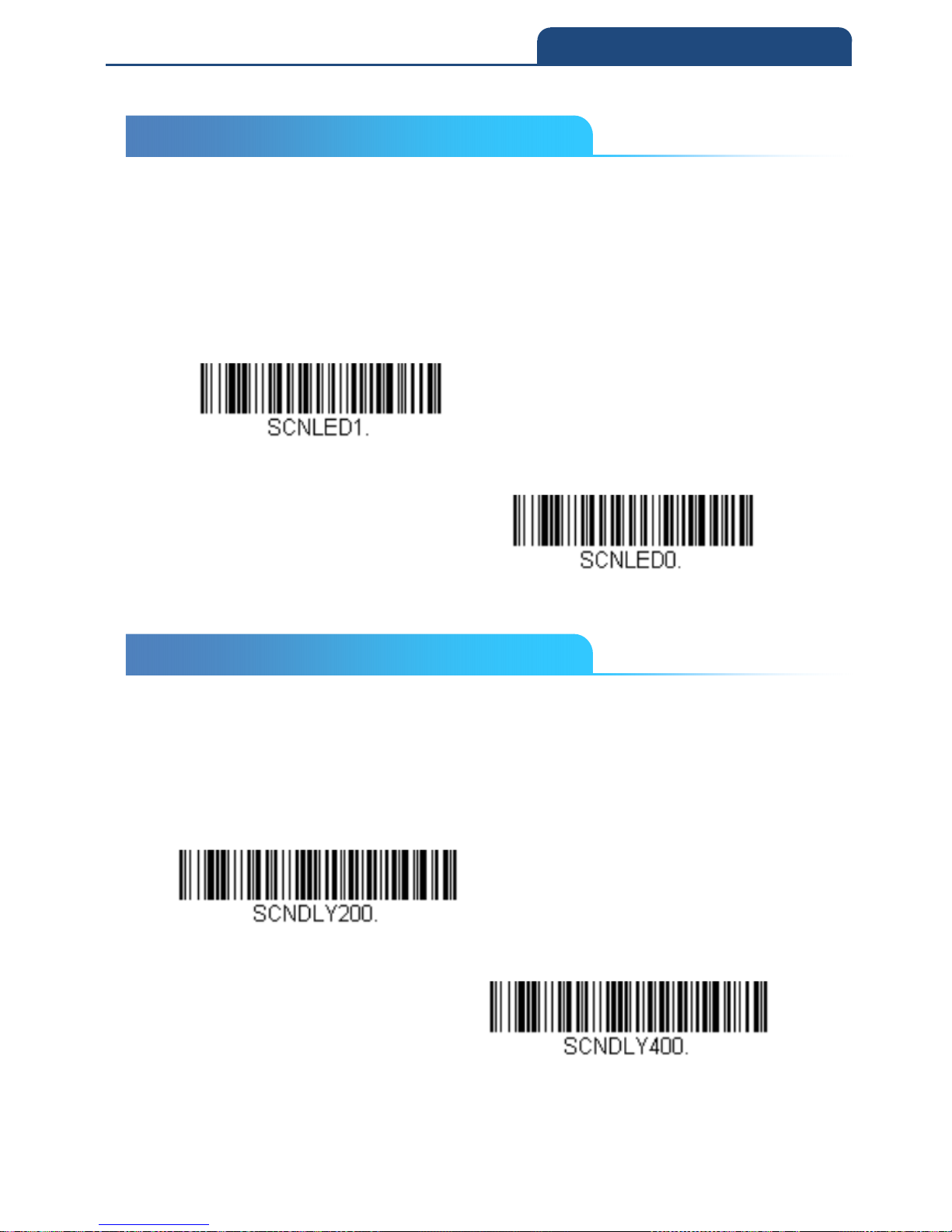
200 milliseconds
400 milliseconds
3-17 Illumination Lights
3-18 Aimer Delay
Page 67
67
3. INPUT/OUTPUT SETTINGS
Off(No display)
3-18-1 User-Specified Aimer Delay
If you want to set your own length for the duration of the delay, scan the bar
code below, then set the time-out by scanning digits (0 - 4,000 ms) from the
Programming Chart inside the back cover of this manual, then scan Save.
Delay Duration
3-19 Aimer Mode
This feature allows you to turn the aimer on and off. When turning the aimer on,
there are 2 options: Interlaced (the aimer is interlaced with the illumination
LEDs) and Interlace Optimized for Decode (same as Interlaced except the
aimer flashes so that it is not captured in the image).
Note: If you are having a hard time decoding using Interlaced, use Interlaced
Optimized for Decode.
Off
3-18-1 User-Specified Aimer Delay
3-19 Aimer Mode
Page 68
68
3. INPUT/OUTPUT SETTINGS
Interlaced
Interlace Optimized for Decode
3-20 Centering
Use Centering to narrow the scan engine’s field of view to make sure that
when the scanner is hand-held, it reads only those bar codes intended by the
user. For instance, if multiple codes are placed closely together, centering will
insure that only the desired codes are read. (Centering can be used in
conjunction with Aimer Delay, for the most error-free operation in applications
where multiple codes are spaced closely together. Using the Aimer Delay and
Centering features, the scanner can emulate the operation of older systems,
such as linear laser bar code scanners.)
If a bar code is not touched by a predefined window, it will not be decoded or
output by the scan engine. If centering is turned on by scanning Centering On,
the scan engine only reads codes that pass through the centering window you
specify using the Top of Centering Window and Bottom of Centering Window
bar codes.
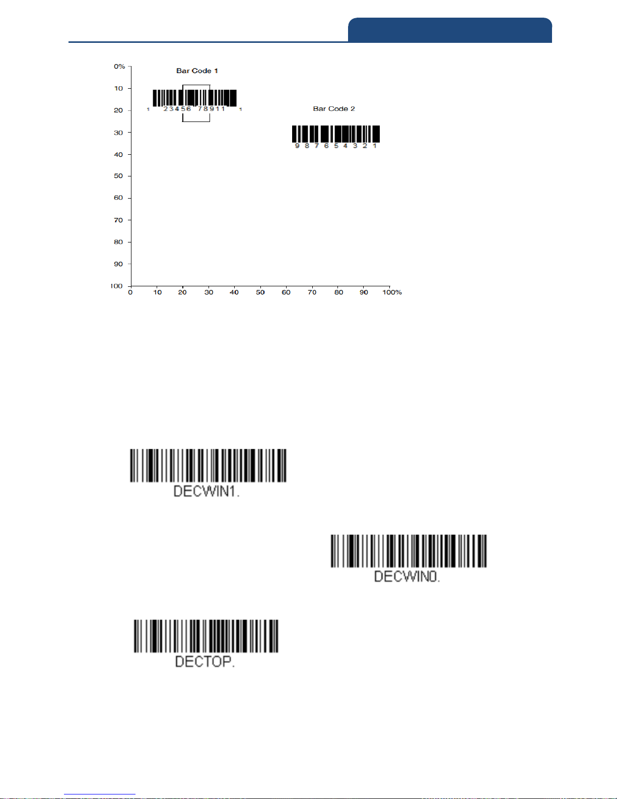
In the example below, the white box is the centering window. The centering
window has been set to 8% top and 25% bottom. Since Bar Code 1 passes
through the centering window, it will be read. Bar Code 2 does not pass
through the centering window, so it will not be read.
3-20 Centering
Page 69
69
3. INPUT/OUTPUT SETTINGS
A bar code needs only to be touched by the centering window in order to be
read. It does not need to pass completely through the centering window.
Scan Centering On, then scan one of the following bar codes to change the top
and bottom of the centering window. Then scan the percent you want to shift
the centering window using digits on the inside back cover of this manual.
Scan Save.
Default Centering = 40% for Top, 60% for Bottom
Centering On
Centering Off
Top of Centering Window
Page 70
70
3. INPUT/OUTPUT SETTINGS
Bottom of Centering Window
3-21 Multiple Symbols
When this programming selection is turned On, it allows you to read multiple
symbols with a single pull of the scanner’s trigger. If you press and hold the
trigger, aiming the scanner at a series of symbols, it reads unique symbols
once, beeping (if turned on) for each read. The scanner attempts to find and
decode new symbols as long as the trigger is pulled. When this programming
selection is turned Off, the scanner will only read the symbol closest to the
aiming beam.
Default = Off
On
Off
3-21 Multiple Symbols
Page 71
71
3. INPUT/OUTPUT SETTINGS
3-22 No Read
With No Read turned On, the scan engine notifies you if a code cannot be read.
If using an EZConfig-Scanning Tool Scan Data Window, an “NR” appears
when a code cannot be read. If No Read is turned Off, the “NR” will not appear.
Default = Off
On
Off
If you want a different notation than “NR,” for example, “Error,” or “Bad Code,”
you can edit the output message (see Data Formatting). The hex code for the
No Read symbol is 9C.
3-23 Video Reverse
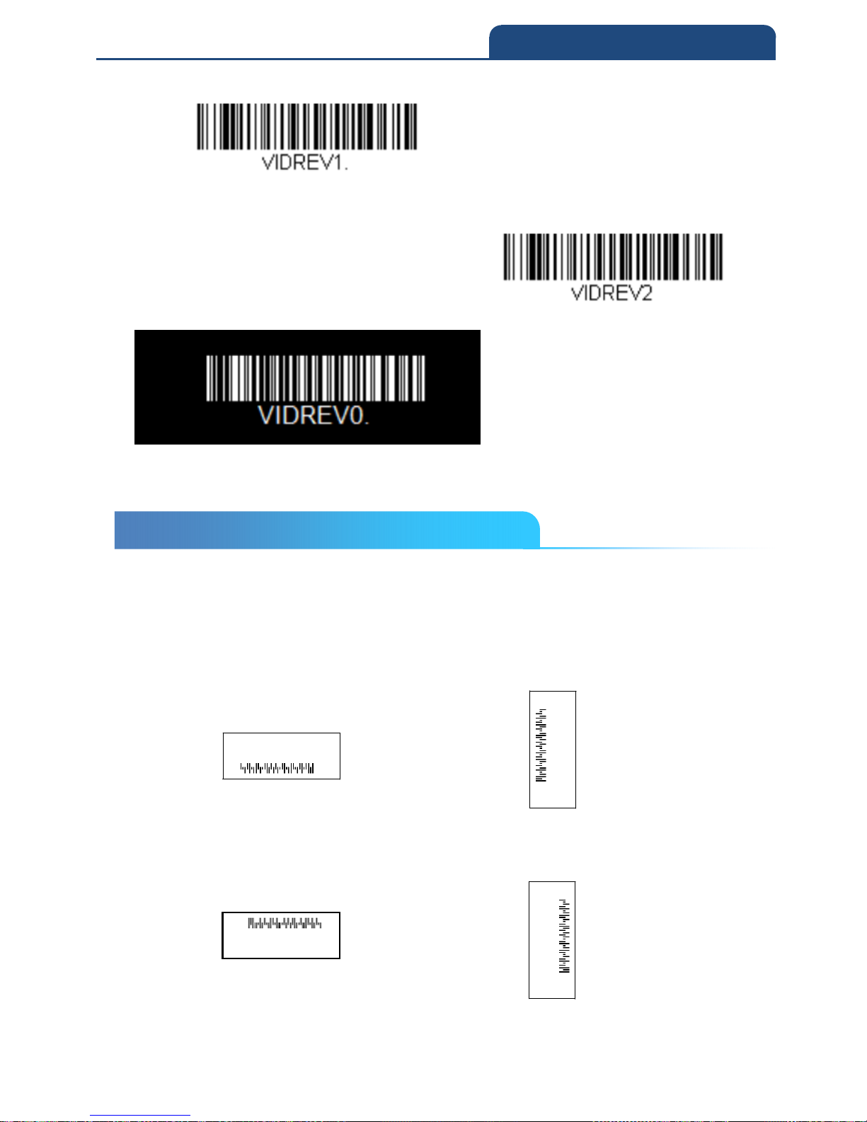
Video Reverse is used to allow the scan engine to read barcodes that are
inverted. The Video Reverse Off barcode below is an example of this type of
barcode. Scan Video Reverse Only to read only inverted barcodes. Scan
Video Reverse and Standard Barcodes to read both types of codes.
Note: After scanning Video Reverse Only, menu barcodes cannot be read. You
must scan Video Reverse Off or Video Reverse and Standard Barcodes in
order to read menu barcodes.
Note: Images downloaded from the unit are not reversed. This is a setting for
decoding only.
3-22 No Read
3-23 Video Reverse
Page 72
72
3. INPUT/OUTPUT SETTINGS
Video Reverse Only
Video Reverse and Standard Bar Codes
Video Reverse Off
3-24 Working Orientation
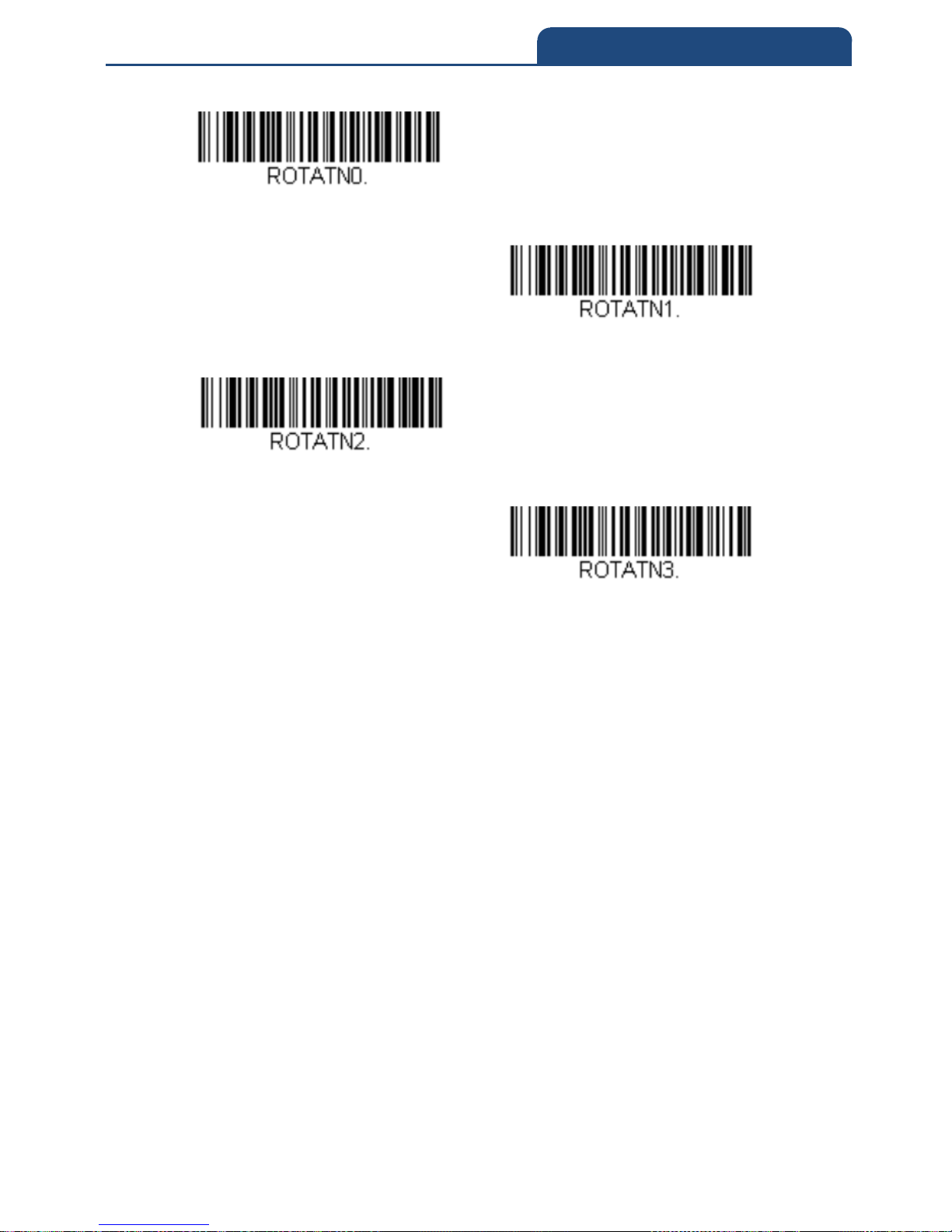
Some barcodes are direction-sensitive. For example, KIX codes and OCR can
misread when scanned sideways or upside down. Use the working orientation
settings if your direction-sensitive codes will not usually be presented upright
to the scanner.
Default = Upright
Upright:
Vertical, Top to Bottom:
(Rotate CW 90°)
Upside Down:
Vertical, Bottom to Top:
(Rotate CCW 90°)
3-24 Working Orientation
Page 73
73
3. INPUT/OUTPUT SETTINGS
Upright
Vertical, Bottom to Top
Upside Down
Vertical, Top to Bottom
Page 74

74
4. DATA EDITING
Chapter 4: DATA EDITING
4-1 Prefix/Suffix Overview
4-1-1 Points to Keep In Mind
4-1-2 To Add a Prefix or Suffix
4-1-3 Example : Add a Tab Suffix to All Symbologies
4-1-4 To Clear One or All Prefixes or Suffixes
4-1-5 To Add a Carriage Return Suffix to All Symbologies
4-2 Prefix Selections
4-3 Suffix Selections
4-4 Function Code Transmit
4-5 Intercharacter, Interfunction, and Intermessage Delays
4-5-1 Intercharacter Delay
4-5-2 User Specified Intercharacter Delay
4-5-3 Interfunction Delay
4-5-4 Intermessage Delay
Page 75
75
4. DATA EDITING
4-1 Prefix/Suffix Overview
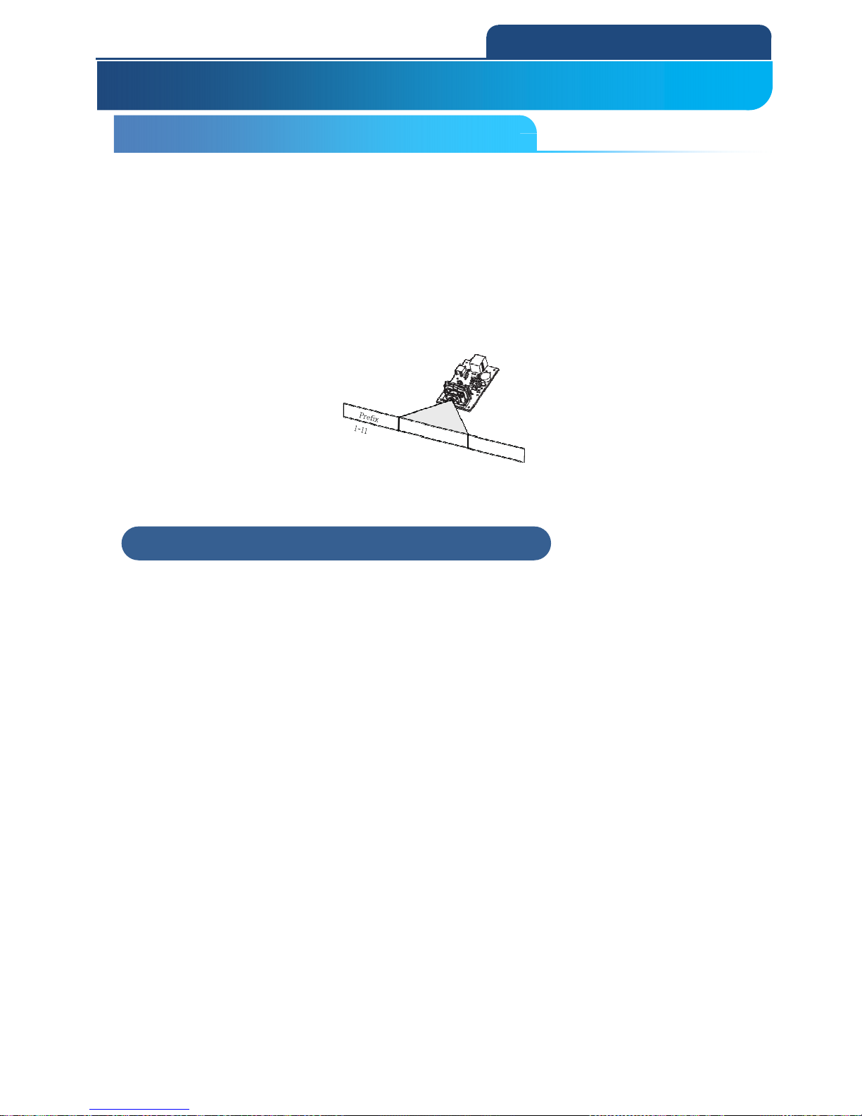
When a barcode is scanned, additional information is sent to the host computer
along with the barcode data. This group of barcode data and additional,
user-defined data is called a “message string.” The selections in this section
are used to build the user-defined data into the message string.
Prefix and Suffix characters are data characters that can be sent before and
after scanned data. You can specify if they should be sent with all symbologies,
or only with specific symbologies. The following illustration shows the
breakdown of a message string:
4-1-1 Points to Keep In Mind
It is not necessary to build a message string. The selections in this chapter are
only used if you wish to alter the default settings.
Default prefix = None Default suffix = None.
A prefix or suffix may be added or cleared from one symbology or all
symbologies.
You can add any prefix or suffix from the ASCII Conversion Chart (Code Page
1252), plus Code I.D. and AIM I.D.
You can string together several entries for several symbologies at one time.
Enter prefixes and suffixes in the order in which you want them to appear on
the output.
When setting up for specific symbologies (as opposed to all symbologies), the
specific symbology ID value counts as an added prefix or suffix character.
The maximum size of a prefix or suffix configuration is 200 characters, which
includes header information.
4. DATA EDITING
4-1 Prefix/Suffix Overview
4-1-1 Points to Keep In Mind
Page 76

76
4. DATA EDITING
4-1-2 To Add a Prefix or Suffix
Step 1. Scan the Add Prefix or Add Suffix symbol.
Step 2. Determine the 2 digit Hex value from the Symbology Chart (included in
the Symbology Charts) for the symbology to which you want to apply the prefix
or suffix. For example, for Code 128, Code ID is “j” and Hex ID is “6A”.
Step 3. Scan the 2 hex digits from the Programming Chart inside the back
cover of this manual or scan 9, 9 for all symbologies.
Step 4. Determine the hex value from the ASCII Conversion Chart (Code Page
1252), for the prefix or suffix you wish to enter.
Note: To add the Code I.D., scan 5, C, 8, 0.
To add AIM I.D., scan 5, C, 8, 1.
To add a backslash (\), scan 5, C, 5, C.
To add a backslash (\), you must scan 5C twice – once to create the leading
backslash and then to create the backslash itself.
Step 5. Scan the 2 digit hex value from the Programming Chart inside the back
cover of this manual.
Step 6. Repeat Steps 4 and 5 for every prefix or suffix character.
Step 7. Scan Save to exit and save, or scan Discard to exit without saving.
Repeat Steps 1-6 to add a prefix or suffix for another symbol.
4-1-3 Example : Add a Tab Suffix to All Symbologies
Step 1. Scan Add Suffix.
Step 2. Scan 9, 9 from the Programming Chart inside the back cover of this
manual to apply this suffix to all symbologies.
Step 3. Scan 0, 9 from the Programming Chart inside the back cover of this
manual. This corresponds with the hex value for a horizontal tab, shown in the
ASCII Conversion Chart (Code Page 1252).
Scan Save, or scan Discard to exit without saving.
4-1-2 To Add a Prefix or Suffix
4-1-3 Example : Add a Tab Suffix to All Symbologies
Page 77

77
4. DATA EDITING
4-1-4 To Clear One or All Prefixes or Suffixes
You can clear a single prefix or suffix, or clear all prefixes/suffixes for a
symbology. If you have been entering prefixes and suffixes for single
symbologies, you can use Clear One Prefix (Suffix) to delete a specific
character from a symbology.
When you Clear All Prefixes (Suffixes), all the prefixes or suffixes for a
symbology are deleted.
Step 1. Scan the Clear One Prefix or Clear One Suffix symbol.
Step 2. Determine the 2 digit Hex value from the Symbology Chart (included in
the Symbology Charts, for the symbology from which you want to clear the
prefix or suffix.
Step 3. Scan the 2 digit hex value from the Programming Chart inside the back
cover of this manual or scan 9, 9 for all symbologies.
Your change is automatically saved.
4-1-5 To Add a Carriage Return Suffix to All Symbologies
Scan the following barcode if you wish to add a carriage return suffix to all
symbologies at once. This action first clears all current suffixes, then programs
a carriage return suffix for all symbologies.
Add CR Suffix All Symbologies
4-1-4 To Clear One or All Prefixes or Suffixes
4-1-5 To Add a Carriage Return Suffix to All Symbologies
Page 78
78
4. DATA EDITING
4-2 Prefix Selections
Add Prefix
Clear One Prefix
Clear All Prefixes
4-3 Suffix Selections
Add Suffix
Clear One Suffix
Clear All Suffix
Example) When setting the prefix of all code symbols (99 hex) to ABC,scan in
the following order.
「Add Prefix」→「9」「9」「4」「1」「4」「2」「4」「3」→「Save」
4-2 Prefix Selections
4-3 Suffix Selections
Page 79
79
4. DATA EDITING
Example) When setting the prefix of all code symbols (99 hex) to standard
code ID, scan in the following order.
「Add Prefix」→「9」「9」「5」「C」「8」「0」→「Save」
Example) To clear all Suffixes of Code 39 (62 hex), scan in the following order.
「Clear all suffix」→「6」「2」
4-4 Function Code Transmit
When this selection is enabled and function codes are contained within the
scanned data, the scan engine transmits the function code to the terminal.
Charts of these function codes are provided in ASCII Conversion Chart (Code
Page 1252) When the scanner is in keyboard wedge mode, the scan code is
converted to a key code before it is transmitted.
Default = Enable
Enable
Disable
4-4 Function Code Transmit
Page 80
80
4. DATA EDITING
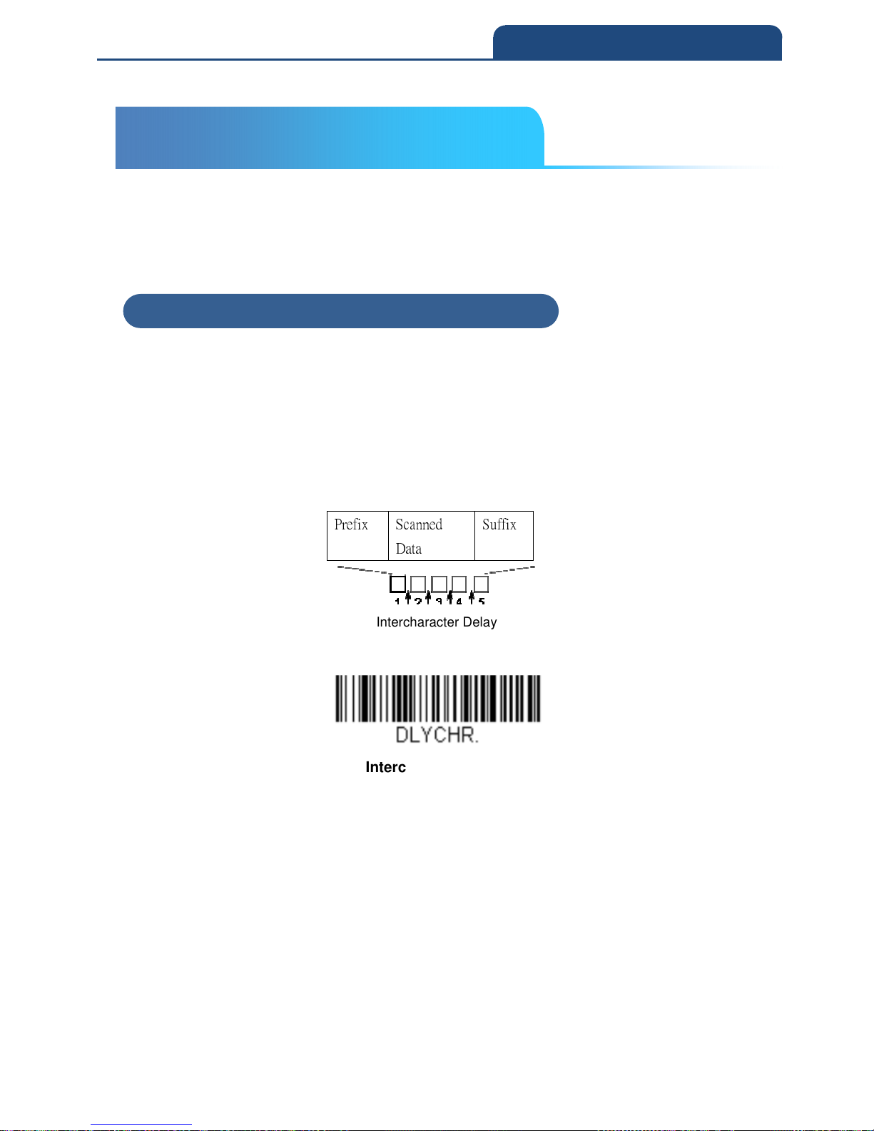
4-5 Intercharacter, Interfunction, and Intermessage Delays
Some terminals drop information (characters) if data comes through too quickly.
Intercharacter, interfunction, and intermessage delays slow the transmission of
data, increasing data integrity.
4-5-1 Intercharacter Delay
An intercharacter delay of up to 5000 milliseconds (in 5ms increments) may be
placed between the transmission of each character of scanned data. Scan the
Intercharacter Delay barcode below, then scan the number of 5ms delays,
and the Save barcode using the Programming Chart inside the back cover of
this manual.
Prefix Scanned
Data
Suffix
Intercharacter Delay
Intercharacter Delay
To remove this delay, scan the Intercharacter Delay barcode, then set the
number of delays to 0. Scan the Save barcode using the Programming Chart
inside the back cover of this manual.
Note: Intercharacter delays are not supported in USB serial emulation.
4-5 Intercharacter, Interfunction, and
Intermessage Delays
4-5-1 Intercharacter Delay
Page 81
81
4. DATA EDITING
4-5-2 User Specified Intercharacter Delay
An intercharacter delay of up to 5000 milliseconds (in 5ms increments) may be
placed after the transmission of a particular character of scanned data. Scan
the Delay Length bar code below, then scan the number of 5ms delays, and
the Save barcode using the Programming Chart inside the back cover of this
manual. Next, scan the Character to Trigger Delay bar code, then the 2-digit
hex value for the ASCII character that will trigger the delay ASCII Conversion
Chart (Code Page 1252).
Delay Length
Character to Trigger Delay
To remove this delay, scan the Delay Length bar code, and set the number of
delays to 0. Scan the Save barcode using the Programming Chart inside the
back cover of this manual.
4-5-2 User Specified Intercharacter Delay
Page 82
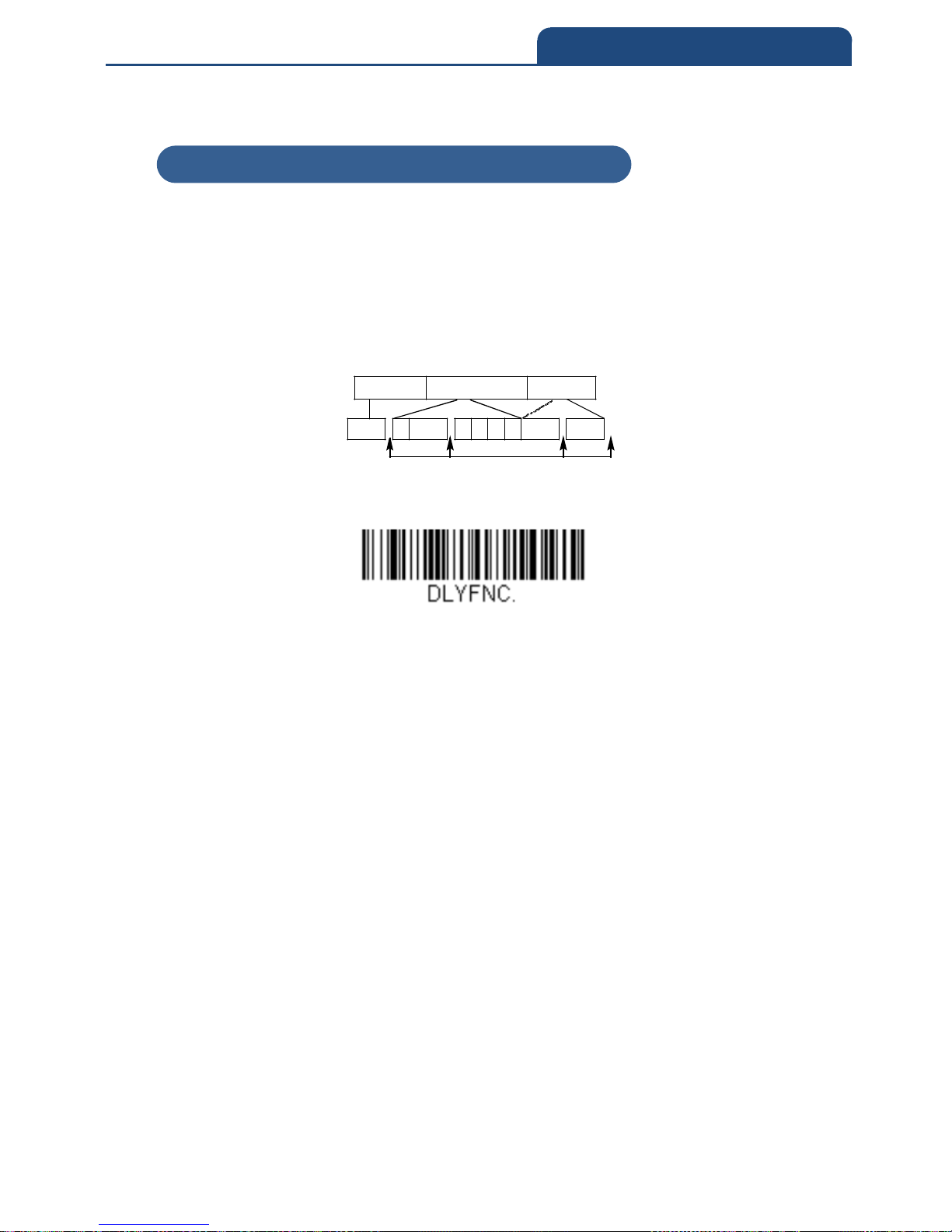
82
4. DATA EDITING
4-5-3 Interfunction Delay
An interfunction delay of up to 5000 milliseconds (in 5ms increments) may be
placed between the transmission of each control character in the message
string. Scan the Interfunction Delay barcode below, then scan the number of
5ms delays, and the Save barcode using the Programming Chart inside the
back cover of this manual.
Interfunction Delays
Interfunction Delay
To remove this delay, scan the Interfunction Delay barcode, then set the
number of delays to 0. Scan the Save barcode using the Programming Chart
inside the back cover of this manual.
4-5-3 Interfunction Delay
Prefix Scanned Data
Suffix
STX 1 HT 2 3 4 5 CR
LF
Page 83
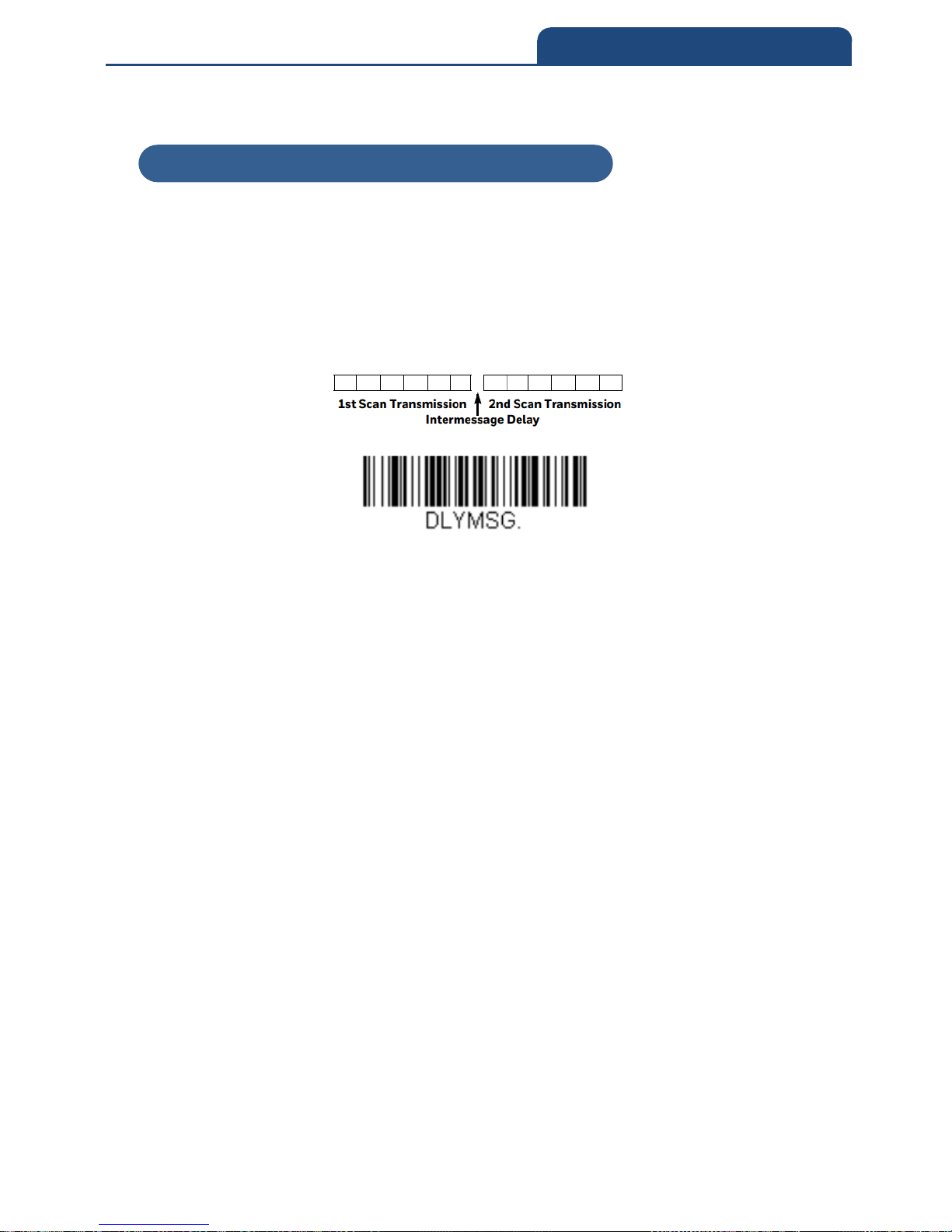
83
4. DATA EDITING
4-5-4 Intermessage Delay
An intermessage delay of up to 5000 milliseconds (in 5ms increments) may be
placed between each scan transmission. Scan the Intermessage Delay bar
code below, then scan the number of 5ms delays, and the Save barcode using
the Programming Chart inside the back cover of this manual.
Intermessage Delay
To remove this delay, scan the Intermessage Delay bar code, then set the
number of delays to 0. Scan the Save barcode using the Programming Chart
inside the back cover of this manual.
4-5-4 Intermessage Delay
Page 84

84
5. DATA FORMATTING
Chapter 5: DATA FORMATTING
5-1 Data Format Editor Introduction
5-2 Add a Data Format
5-2-1 Other Programming Selections
5-3 Terminal ID Table
5-4 Data Format Editor Commands
5-4-1 Send Commands
5-4-2 Move Commands
5-4-3 Search Commands
5-4-4 Miscellaneous Commands
5-5 Data Formatter
5-6 Primary/Alternate Data Formats
Page 85

85
5. DATA FORMATTING
5-1 Data Format Editor Introduction
You may use the Data Format Editor to change the scan engine’s output. For
example, you can use the Data Format Editor to insert characters at certain
points in barcode data as it is scanned. The selections in the following pages
are used only if you wish to alter the output.
Default Data Format setting = None
Normally, when you scan a barcode, it is output automatically. However, when
you create a format, you must use a “send” command within the format
program to output data.
Multiple formats may be programmed into the scan engine. They are stacked
in the order in which they are entered. However, the following list presents the
order in which formats are applied:
Specific Terminal ID, Actual Code ID, Actual Length
Specific Terminal ID, Actual Code ID, Universal Length
Specific Terminal ID, Universal Code ID, Actual Length
Specific Terminal ID, Universal Code ID, Universal Length
Universal Terminal ID, Actual Code ID, Actual Length
Universal Terminal ID, Actual Code ID, Universal Length
Universal Terminal ID, Universal Code ID, Actual Length
Universal Terminal ID, Universal Code ID, Universal Length
The maximum size of a data format configuration is 2000 bytes, which includes
header information.
If a barcode is read that fails the first data format, the next data format, if there
is one, will be used on the barcode data. If there is no other data format, the
raw data is output.
If you have changed data format settings, and wish to clear all formats and
return to the factory defaults, scan the Default Data Format code below.
Default Data Format
5. DATA FORMATTING
5-1 Data Format Editor Introduction
Page 86

86
5. DATA FORMATTING
5-2 Add a Data Format
Step1. Scan the Enter Data Format symbol
Step2. Select Primary/Alternate Format
Determine if this will be your primary data format, or one of 3 alternate
formats. This allows you to save a total of 4 different data formats. To
program your primary format, scan 0 using the Programming Chart inside
the back cover of this manual. If you are programming an alternate format,
scan 1, 2, or 3, depending on which alternate format you are
programming. (See "Primary/Alternate Data Formats" for further
information.)
Step3. Terminal Type
Refer to Terminal ID Table and locate the Terminal ID number for your
PC. Scan three numeric bar codes on the inside back cover to program
the scan engine for your terminal ID (you must enter 3 digits). For
example, scan 0 0 3 for an AT wedge.
Note: 099 indicates all terminal types.
Step 4. Code I.D.
In the Symbology Charts, find the symbology to which you want to apply
the data format. Locate the Hex value for that symbology and scan the 2
digit hex value from the Programming Chart inside the back cover of this
manual.
If you are creating a data format for Batch Mode Quantity, use 35 for the Code
I.D
Note: 99 indicates all symbologies.
Step 5. Length
Specify what length (up to 9999 characters) of data will be acceptable for
this symbology. Scan the four digit data length from the Programming
Chart inside the back cover of this manual. For example, 50 characters is
entered as 0050.
Note: 9999 indicates all lengths.
Step 6. Editor Commands
Refer to Data Format Editor Commands. Scan the symbols that
represent the command you want to enter.
Step 7. Scan Save to save your data format, or Discard to exit without saving
your changes.
5-2 Add a Data Format
Page 87
87
5. DATA FORMATTING
Enter Data Format
5-2-1 Other Programming Selections
• Clear One Data Format
This deletes one data format for one symbology. If you are clearing the
primary format, scan 0 from the Programming Chart inside the back cover
of this manual. If you are clearing an alternate format, scan 1, 2, or 3,
depending on the format you are clearing. Scan the Terminal Type and
Code I.D. (see Symbology Charts), and the bar code data length for the
specific data format that you want to delete. All other formats remain
unaffected.
• Clear all Data Formats
This clears all data formats.
• Save to exit and save your data format changes.
• Discard to exit without saving any data format changes.
Clear One Data Format
Clear All Data Formats
5-2-1 Other Programming Selections
Page 88
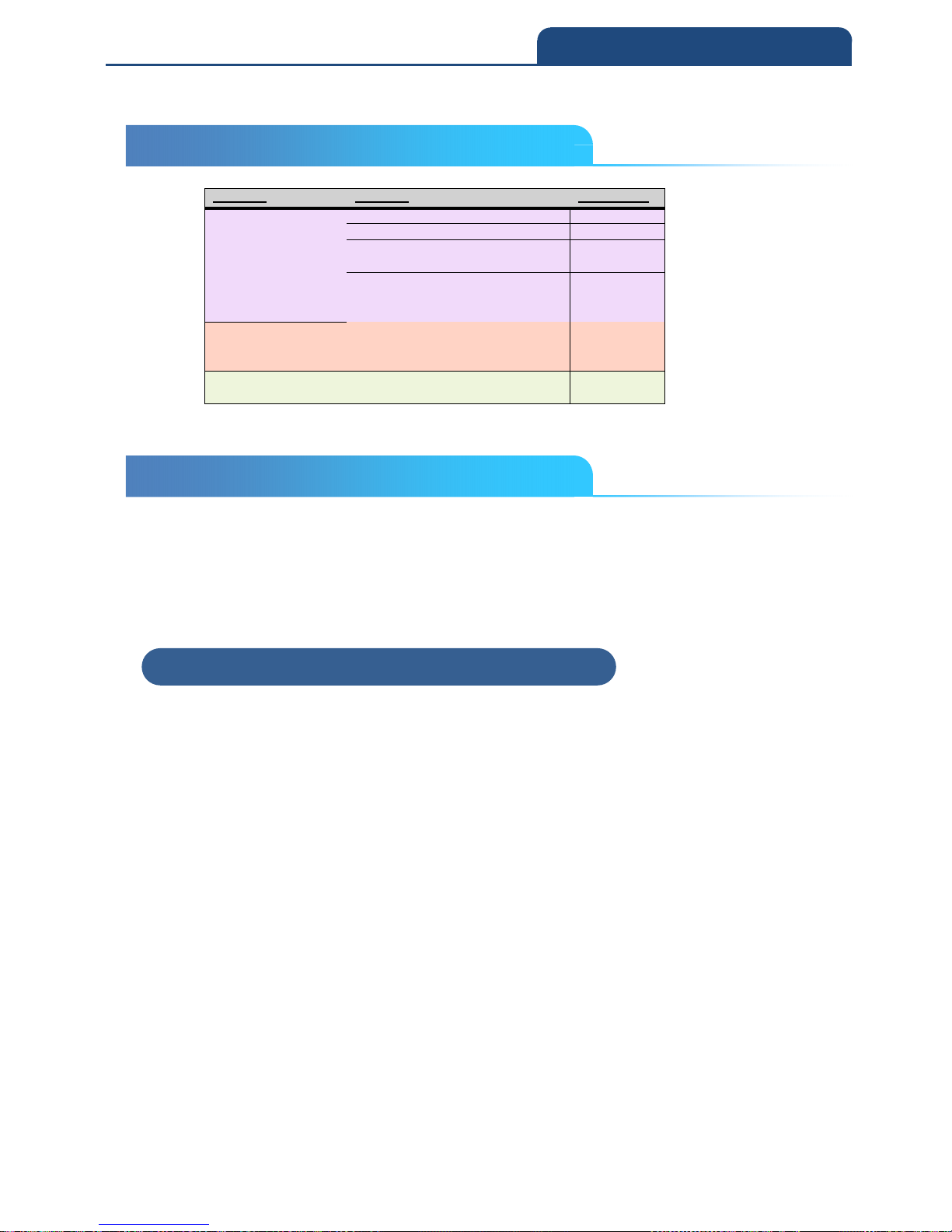
88
5. DATA FORMATTING
5-3 Terminal ID Table
Terminal
Model(s)
Terminal
ID
USB PC keyboard (HID)
124
Mac Keyboard
125
PC Keyboard (Japanese)
134
Serial (COM driver required)
130
HID POS
131
USB SurePOS Handheld
128
USB SurePOS Tabletop
129
Serial
RS232 TTL
000
RS23
2 True
000
RS485 (IBM
-
HHBCR 1+2, 46xx)
051
Keyboard
PS2 compatibles
003
AT compatibles
002
5-4 Data Format Editor Commands
When working with the Data Format Editor, a virtual cursor is moved along
your input data string. The following commands are used to both move this
cursor to different positions, and to select, replace, and insert data into the final
output.
5-4-1 Send Commands
F1-Send all characters
Include in the output message all of the characters from the input message,
starting from current cursor position, followed by an insert character. Syntax =
F1xx where xx stands for the insert character’s hex value for its ASCII code.
Refer to the ASCII Conversion Chart, for decimal, hex and character codes.
F2-Send a number of characters
Include in the output message a number of characters followed by an insert
character. Start from the current cursor position and continue for “nn”
characters or through the last character in the input message, followed by
character “xx.” Syntax = F2nnxx where nn stands for the numeric value (00-99)
for the number of characters, and xx stands for the insert character’s hex value
for its ASCII code. Refer to the ASCII Conversion Chart, for decimal, hex and
character codes.
5-3 Terminal ID Table
5-4 Data Format Editor Commands
5-4-1 Send Commands
Page 89

89
5. DATA FORMATTING
Example: Send a number of characters
Send the first 10 characters from the barcode above, followed by a carriage
return. Command string: F2100D
F2 is the “Send a number of characters” command 10 is the number of
characters to send
0D is the hex value for a CR
The data is output as: 1234567890
Example: Split characters into 2 lines
Send the first 10 characters from the barcode above, followed by a carriage
return, followed by the rest of the characters.
Command string: F2100DF10D
F2 is the “Send a number of characters” command
10 is the number of characters to send for the first line 0D is the hex value for a
CR
F1 is the “Send all characters” command 0D is the hex value for a CR
The data is output as: 1234567890 ABCDEFGHIJ
<CR>
F3-Send all characters up to a particular character
Include in the output message all characters from the input message, starting
with the character at the current cursor position and continuing to, but not
including, the search character “ss,” followed by an insert character. The
cursor is moved forward to the “ss” character. Syntax = F3ssxx where ss stands
for the search character’s hex value for its ASCII code, and xx stands for the
insert character’s hex value for its ASCII code.
Refer to the ASCII Conversion Chart, for decimal, hex and character codes.
F3 Example: Send all characters up to a particular character
Using the barcode above, send all characters up to but not including “D,”
followed by a carriage return. Command string: F3440D
F3 is the “Send all characters up to a particular character” command 44 is the
hex value for a 'D”
0D is the hex value for a CR
The data is output as:
Page 90
90
5. DATA FORMATTING
1234567890ABC
<CR>
E9-Send all but the last characters
Include in the output message all but the last “nn” characters, starting from the
current cursor position. The cursor is moved forward to one position past the
last input message character included. Syntax = E9nn where nn stands for the
numeric value (00-99) for the number of characters that will not be sent at the
end of the message.
F4—Insert a character multiple times
Send “xx” character “nn” times in the output message, leaving the cursor in the
current position. Syntax = F4xxnn where xx stands for the insert character’s
hex value for its ASCII code, and nn is the numeric value (00-99) for the
number of times it should be sent. Refer to the ASCII Conversion Chart (Code
Page 1252), for decimal, hex and character codes.
Example: Send all but the last characters, followed by 2 tabs (E9 and F4)
Send all characters except for the last 8 from the bar code above, followed by
2 tabs.
Command string: E908F40902
E9
08
F4
09
02
“Send all but the last characters” command
Number of characters at the end to ignore
“Insert a character multiple times” command
Hex value for a horizontal tab
Number of times the tab character is sent
The data is output as: 1234567890AB <tab><tab>
Page 91
91
5. DATA FORMATTING
5-4-2 Move Commands
F5—Move the cursor forward a number of characters
Move the cursor ahead “nn” characters from current cursor position. Syntax =
F5nn where nn is the numeric value (00-99) for the number of characters the
cursor should be moved ahead.
Example: Move the cursor forward and send the data
Move the cursor forward 3 characters, then send the rest of the bar code data
from the bar code above. End with a carriage return.
Command string: F503F10D
F5
03
F1
0D
“Move the cursor forward a number of characters” command
Number of characters to move the cursor
“Send all characters” command
Hex value for a CR
The data is output as:
4567890ABCDEFGHIJ
<CR>
F6—Move the cursor backward a number of characters
Move the cursor back “nn” characters from current cursor position. Syntax =
F6nn where nn is the numeric value (00-99) for the number of characters the
cursor should be moved back.
F7—Move the cursor to the beginning
Move the cursor to the first character in the input message. Syntax = F7.
Example: Manipulate bar codes that begin with a 1 (FE and F7)
Search for bar codes that begin with a 1. If a bar code matches, move the
5-4-2 Move Commands
Page 92
92
5. DATA FORMATTING
cursor back to the beginning of the data and send 6 characters followed by a
carriage return. Using the bar code above:
Command string: FE31F7F2060D
FE
31
F7
F2
06
0D
“Compare characters” command
Hex value for 1
“Move the cursor to the beginning” command
“Send a number of characters” command
Number of characters to send
Hex value for a CR
The data is output as:
123456
<CR>
5-4-3 Search Commands
F8—Search forward for a character
Search the input message forward for “xx” character from the current cursor
position, leaving the cursor pointing to the “xx” character. Syntax = F8xx where
xx stands for the search character’s hex value for its ASCII code. Refer to the
ASCII Conversion Chart (Code Page 1252), for decimal, hex and character
codes.
Example: Send bar code data that starts after a particular character
Search for the letter “D” in bar codes and send all the data that follows,
including the “D.” Using the bar code above:
Command string: F844F10D
F8
44
F1
0D
“Search forward for a character” command
Hex value for “D”
“Send all characters” command
Hex value for a CR
The data is output as:
DEFGHIJ
<CR>
5-4-3 Search Commands
Page 93
93
5. DATA FORMATTING
F9—Search backward for a character
Search the input message backward for “xx” character from the current cursor
position, leaving the cursor pointing to the “xx” character. Syntax = F9xx where
xx stands for the search character’s hex value for its ASCII code. Refer to the
ASCII Conversion Chart (Code Page 1252), for decimal, hex and character
codes.
E6—Search forward for a non-matching character
Search the input message forward for the first non-“xx” character from the
current cursor position, leaving the cursor pointing to the non-“xx” character.
Syntax = E6xx where xx stands for the search character’s hex value for its
ASCII code. Refer to the ASCII Conversion Chart (Code Page 1252), for
decimal, hex and character codes.
Example: Remove zeroes at the beginning of bar code data
This example shows a bar code that has been zero filled. You may want to
ignore the zeroes and send all the data that follows. E6 searches forward for
the first character that is not zero, then sends all the data after, followed by a
carriage return. Using the bar code above:
Command string: E630F10D
E6
30
F1
0D
“Search forward for a non-matching character” command
Hex value for 0
“Send all characters” command
Hex value for a CR
The data is output as:
37692
<CR>
E7—Search backward for a non-matching character
Search the input message backward for the first non-“xx” character from the
current cursor position, leaving the cursor pointing to the non-“xx” character.
Syntax = E7xx where xx stands for the search character’s hex value for its
ASCII code. Refer to the ASCII Conversion Chart (Code Page 1252), for
decimal, hex and character codes.
Page 94
94
5. DATA FORMATTING
5-4-4 Miscellaneous Commands
FB—Suppress characters
Suppress all occurrences of up to 15 different characters, starting at the
current cursor position, as the cursor is advanced by other commands. When
the FC command is encountered, the suppress function is terminated. The
cursor is not moved by the FB command.
Syntax = FBnnxxyy .. zz
where nn is a count of the number of suppressed characters in the list, and
xxyy .. zz is the list of characters to be suppressed.
Example: Remove spaces in bar code data
This example shows a bar code that has spaces in the data. You may want to
remove the spaces before sending the data. Using the bar code above:
Command string: FB0120F10D
FB
01
20
F1
0D
“Suppress characters” command
Number of character types to be suppressed
Hex value for a space
“Send all characters” command
Hex value for a CR
The data is output as:
34567890
<CR>
FC—Stop suppressing characters
Disables suppress filter and clear all suppressed characters. Syntax = FC
E4—Replace characters
Replaces up to 15 characters in the output message, without moving the
cursor. Replacement continues until the E5 command is encountered. Syntax
= E4nnxx- 1xx2yy1yy2...zz1zz2 where nn is the total count of the number of
characters in the list (characters to be replaced plus replacement characters);
xx1 defines characters to be replaced and xx2 defines replacement characters,
continuing through zz1 and zz2
Example: Replace zeroes with CRs in bar code data
5-4-4 Miscellaneous Commands
Page 95

95
5. DATA FORMATTING
If the bar code has characters that the host application does not want included,
you can use the E4 command to replace those characters with something else.
In this example, you will replace the zeroes in the bar code above with carriage
returns.
Command string: E402300DF10D
E4
02
30
0D
F1
0D
“Replace characters” command
Total count of characters to be replaced, plus the replacement characters
(0 is replaced by CR, so total characters = 2)
Hex value for 0
Hex value for a CR (the character that will replace the 0)
“Send all characters” command
Hex value for a CR
The data is output as:
1234
5678
ABC
<CR>
E5—Stop replacing characters
Terminates character replacement. Syntax = E5
FE—Compare characters
Compare the character in the current cursor position to the character “xx.” If
characters are equal, move the cursor forward one position. Syntax = FExx
where xx stands for the comparison character’s hex value for its ASCII code.
Refer to the ASCII Conversion Chart (Code Page 1252), for decimal, hex and
character codes.
EC—Check for a number
Check to make sure there is an ASCII number at the current cursor position.
The format is aborted if the character is not numeric. Example: Only output the
data if the bar code begins with a number If you want only data from bar codes
that begin with a number, you can use EC to check for the number.
Command string: ECF10D
FC
F1
0D
“Check for a number” command
“Send all characters” command
Hex value for a CR
Page 96
96
5. DATA FORMATTING
If this bar code is read, the next data format, if there is one,
will be used on the data. If there is no other format, the format fails and the raw
data is output as AB1234.
If this bar code is read: the data is output as:
1234AB
<CR
ED—Check for non-numeric character
Check to make sure there is a non-numeric ASCII character at the current
cursor position.
The format is aborted if the character is numeric.
Example: Only output the data if the bar code begins with a letter
If you want only data from bar codes that begin with a letter, you can use ED to
check for the letter.
Command string: EDF10D
ED
F1
0D
“Check for a non-numeric character” command
“Send all characters” command
Hex value for a CR
If this bar code is read, the next data format, if there is one, will
be used on this data. If there is no other format, the format fails and the raw
data is output as 1234AB.
If this bar code is read: the data is output as:
AB1234
<CR>
EF—Insert a delay
Inserts a delay of up to 49,995 milliseconds (in multiples of 5), starting from the
current cursor position. Syntax = EFnnnn where nnnn stands for the delay in
5ms increments, up to 9999. This command can only be used with keyboard
emulation.
Page 97
97
5. DATA FORMATTING
5-5 Data Formatter
When Data Formatter is turned Off, the bar code data is output to the host as
read, including prefixes and suffixes.
Data Formatter Off
You may wish to require the data to conform to a data format you have created
and saved. The following settings can be applied to your data format:
• Data Formatter On, Not Required, Keep Prefix/Suffix
Scanned data is modified according to your data format, and prefixes and
suffixes are transmitted.
• Data Format Required, Keep Prefix/Suffix
Scanned data is modified according to your data format, and prefixes and
suffixes are transmitted. Any data that does not match your data format
requirements generates an error tone and the data in that bar code is not
transmitted. If you wish to process this type of bar code without generating an
error tone, see Primary/Alternate Data Formats.
Choose one of the following options.
Default = Data Formatter On, Not Required, Keep Prefix/Suffix
Data Formatter On, Not Required,
Keep Prefix/Suffix
Data Format Required, Keep
Prefix/Suffix
5-5 Data Formatter
Page 98
98
5. DATA FORMATTING
5-6 Primary/Alternate Data Formats
You can save up to four data formats, and switch between these formats. Your
primary data format is saved under 0. Your other three formats are saved
under 1, 2, and 3. To set your device to use one of these formats, scan one of
the bar codes below.
Primary Data Format
Data Format 1
Data Format 2
Data Format 3
5-6 Primary/Alternate Data Formats
Page 99

99
6. SYMBOLOGIES
Chapter 6: SYMBOLOGIES
6-1 All Symbologies
6-2 Message Length Description
6-3 Codabar
6-3-1 Codabar On/Off
6-3-2 Codabar Start/Stop Characters
6-3-3 Codabar Check Character
6-3-4 Codabar Concatenation
6-3-5 Codabar Message Length
6-4 Code 39
6-4-1 Code 39 On/Off
6-4-2 Code 39 Start/Stop Characters
6-4-3 Code 39 Check Character
6-4-4 Code 39 Message Length
6-4-5 Code 39 Append
6-4-6 Code 39 Pharmaceutical ( PARAF )
6-4-7 Full ASCII
6-4-8 Code 39 Code Page
6-5 Interleaved 2 of 5
6-5-1 Interleaved 2 of 5 On/Off
6-5-2 Check Digit
6-5-3 Interleaved 2 of 5 Message Length
6-6 NEC 2 of 5
6-6-1 NEC 2 of 5 On/Off
6-6-2 Check Digit
6-6-3 NEC 2 of 5 Message Length
6-7 Code 93
6-7-1 Code 93 On/Off
6-7-2 Code 93 Message Length
6-7-3 Code 93 Append
6-7-4 Code 93 Code Page
6-8 Straight 2 of 5 Industrial ( three-bar start/stop )
6-8-1 Straight 2 of 5 Industrial On/Off
6-8-2 Straight 2 of 5 Industrial Message Length
6-9 Straight 2 of 5 IATA ( two-bar start/stop )
6-9-1 Straight 2 of 5 IATA On/Off
6-9-2 Straight 2 of 5 IATA Message Length
Page 100

100
6. SYMBOLOGIES
6-10 Matrix 2 of 5
6-10-1 Matrix 2 of 5 On/Off
6-10-2 Matrix 2 of 5 Message Length
6-11 Code 11
6-11-1 Code 11 On/Off
6-11-2 Check Digits Required
6-11-3 Code 11 Message Length
6-12 Code 128
6-12-1 Code 128 On/Off
6-12-2 ISBT 128 Concatenation
6-12-3 Code 128 Message Length
6-12-4 Code 128 Append
6-12-5 Code 128 Code Page
6-13 GS1-128
6-13-1 GS1-128 On/Off
6-13-2 GS1-128 Message Length
6-14 UPC-A
6-14-1 UPC-A On/Off
6-14-2 Convert UPC-A to EAN-13
6-14-3 UPC-A Check Digit
6-14-4 UPC-A Number System
6-14-5 UPC-A Addenda
6-14-6 UPC-A Addenda Required
6-14-7 UPC-A Addenda Separator
6-15 UPC-A/EAN-13 with Extended CouponCode
6-16 Coupon GS1 Databar Output
6-17 UPC-E
6-17-1 UPC-E0/ UPC-E1 On/Off
6-17-2 UPC-E0 Expand
6-17-3 UPC-E0 Addenda Required
6-17-4 UPC-E0 Addenda Separator
6-17-5 UPC-E0 Check Digit
6-17-6 UPC-E0 Leading Zero
6-17-7 UPC-E0 Addenda
6-18 EAN/JAN-13
6-18-1 EAN/JAN-13 On/Off
6-18-2 EAN/JAN-13 Check Digit
6-18-3 EAN/JAN-13 Addenda
6-18-4 EAN/JAN-13 Addenda Required
6-18-5 EAN/JAN-13 Addenda Separator
 Loading...