

Page 1

INSTALLATION AND USER’S MANUAL
CONTENT
INTRODUCTION
SAFETY PRECAUTION
SPECIFICATION 31
INSTALLATION
INSTALLATION (VENT INSIDE)
DESCRIPTION OF COMPONENTS
OPERATION
MAINTENANCE
TROBULESHOOTING
CONFORMITY WITH DIRECTIVES
ENVIRONMENTAL PROTECTION
(VENT OUTSIDE)
29
29
32
36
37
38
38
39
40
40
29
Page 2

INTRODUCTION
Thank you for choosing this cooker hood.
This instruction manual is designed to provide you with all required
instructions related to the installation, use and maintenance of the appliance.
In order to operate the unit correctly and safety, pl ease read this instruction
manual carefully before installation and usage.
The cooker hood uses high quality materials, and is made with a streamlined
design. Equipped with large power electric motor and cent rifugal fan, it also
provides strong suction power, low nois e operati on, non-stick grease filter and
easy assembly installation.
SAFETY PRECAUTION
Never let the children operate the machine.
The cooker hood is for home use only, not suitable for barbecue, roast
shop and other commercial purpose.
The cooker hood and its filter should be clean regularly in order to
keep in good working condition.
Clean the cooker hood according to the instruction manual and keep
the unit from danger of burning.
Forbid the direct baking from the gas cooker.
Please keep the kitchen room a good convection.
Before connecting this appliance check that the power supply cord is
not damaged. A damage supply cord must be replaced by qualified
service personnel only.
There shall be adequate ventilation of the room when the rang e hood
is used at the same time as appliances burning ga s or other fuels;
he air must not be discharged into a flue that is used for
exhausting fumes from appliances burning ga s or other fuels;
Regulations concerning the discharge of air have to be fulfilled.
This appliance if not intended for use by persons(including children)
with reduced physical, sensory or mental capabilities, or lack of
experience and knowledge, unless they have been given supervision
or instruction concerning use of the appliance by a person slide for
their safety.
Children should be supervised to ensure that they do not play with the
appliance.
Do not flambé under the range hood.
The range hood is not intended to be installed over a hob having more
than four hob elements
30
Page 3

Electrical Shock Hazard
Only plug this unit into a properly earthed outlet. If in doubt seek
advice from a suitably qualified engineer.
Failure to follow these instructions can result i n death, fire, or
electrical shock.
31
Page 4
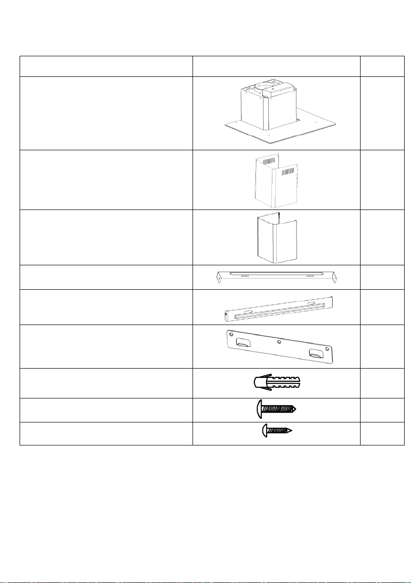
Standard Installation Accessories List
Spec.
Illustration Picture
Qty
Casing
1
Upper Chimney
1
Lower Chimney
1
Upper chimney bracket
1
φ8 rawl plugs
9
Screws
ST4.0×30
9
φ7.2screws
ST4.0×8
2
Lower chimney bracket
Hanging Board
φ8×φ6 white color
32
1
1
Page 5

INSTALLATION (wall mounting)
If you have an outlet to the outside, your cooker hood can be connected as
below picture by means of an extraction duct (enamel, aluminum, flexible pipe or
inflammable material with an interior diamet er of 150mm)
1. Before installation, turn the uni t off and unplug it from the outlet.
2. The cooker hood should be place d at a distance of 65~75cm above
the cooking plane for best effect.
3. Drill 3 x 8mm holes to accommodate the bracket. Screw and tighten
the bracket onto the wall with the screws provided.
Screw(4mm x 30mm)
33
Wall plug
Wall bracket
107.5mm
Page 6

4. Leave up the cooker hood and hang onto the wall bracket hook.
Cooker hook
Wall
bracket
5. Fix the one-way-valve to the air outlet of the cooker hood. Then,
attached the exhaust pipe onto the one-way-valve as shown below.
Exhaust pipe
Cooker hood
34
Page 7

6.
i. Place the glass in appropriate position on the top the cooker
hood.
ii. Fix with 4 screws and washer. In order to avoid the gla ss
cracking, please do not tighten the screws too strongly.
i. By Put the inner chimney into outer chimney .Then pulling out
the inner chimney upwards. Adjust to reach the heigh t required.
ii. Sliding the chimney to adjust the chimney heigh t. When the
height you required is reached, then han g the fix ing hole t o the fi xing
screws as showed in below pictures.
Inner chimney
Outer chimney
35
Page 8

8.
Wall plug
i. Drill 2 x 8mm holes to accommodate the plate II. Screw and
tighten the plate II onto the wall with 2 screws provided.
ii. Assembly the chimney onto the unit and fix it with 2 screws.
Plate II
Screw
4mm x 8mm
Screw
(4mm x 30mm)
36
Page 9

INSTALLATION (VENT INSIDE)
If you do not have an outlet to the outside, exhaust pipe is not required and
the installation is similar to the one show in section “INSTALLATION (VENT
OUTSIDE)”.
Activated carbon filter can be used to trap odor s.
In order to install the activated carbon filter, the grease filter should be
detached first. Press the lock and pull it downward.
Plug the activated carbon filter into the unit and turn it in clockwise direction.
Repeat the same on the other side.
NOTE:
o Make sure the filter is securely locked. Otherwise, it would loosen and
cause dangerous.
o When activated carbon filter attached, the suction power will be
lowere
37
Page 10

DESCRIPTION OF COMPONENTS
OPERATION
Low Speed button 1
It’s used for Ventilation on the kitchen. It i s suit able for simmering and cooking
which do not make much steam.
Medium Speed button 2
Airflow speed is ideally for ventilation in standard cooking operation.
High Speed button 3
When high density of smoke or steam produced, press high-speed button for
highest effective ventilation.
Light button
NOTE: If Low / Medium / High speed buttons are press at the same time, t he
unit will only operate at the highest speed.
38
Page 11

MAINTENANCE
Before cleaning switch the unit off and pull out t he pl ug.
I. Regular Cleaning
Use a soft cloth moistened with hand-warm mildly soapy water or
household cleaning detergent. Never use metal pads, chemical, abrasive
material or stiff brush to clean the unit.
II. Monthly Cleaning for Grease Filter
ESSENTIAL: Clean the filter every month can prevent any risk of fire.
The filter collects grease, smoke and dust….. . so the filter is directly
affecting the efficiency of the cooker hood. If not cleaned, the grease
residue (potential flammable) will saturat e on the filter. Clean it with
household cleaning detergent.
III. Annual Cleaning for Activated Carbon Filter
Apply SOLELY to unit that installed as a recirculation unit (not v ented to
the outside). This filter traps odors and must be replaced at least once a
year
depending on how frequent the cooker hood used.
IV. Changing a light bulb
Remove the screws on the glass, take off the hood glass. Find the
bulb that requires replacement, you will find it located in the light
fixture which is inside the exposed section of the canopy.
Disconnect the light wiring point and remove the bulb holders and
wiring from the hood. Important: It’s not possible to replace the bulbs
individually, it will be necessary to obtain the bulbs, bulb holders and
wiring as a complete part. (LED light: G4, MAX 1.5W)
Fit the replacement bulbs, bulb holders and wiring in the same
manners as the originals. Then reconnect the light wiring point.
39
Page 12

Fault
Cause
Solution
Light on, but
The fan blade is
jammed.
The motor is damaged.
work
rating.
Power cord looses.
Plug in to the power supply again.
The fan blade is
damaged.
Switch of the unit and repair by
qualified service personnel only.
fixed tightly.
qualified service personnel only.
Take down the unit and check
location.
Suction
not good
Too long distance
the cooking plane
Refit the hood glass and fasten the glass screws. Make sure the screws are
fully tightened.
TROBULESHOOTING
fan does not
work
Both light and
fan do not
Halogen light bulb burn.
Switch off the unit and repair by
qualified service personnel only.
Replace the bulb with correct
Serious
Vibration of
the unit
The fan motor is not
The unit is not hung
properly on the bracket.
Switch off the unit and repair by
whether the bracket is in proper
performance
between the unit and
CUSTOMER ASSISTANCE SERVICE
If you cannot identify the cause of the operating ano m al y, switch off the
appliance and contact the Assistance Service.
PRODUCT SERIAL NUMBER. Where can I find it?
It is important you to inform the Assistance Serv ice of your product code
and its serial number (a 16 character code which begins with t he number 3);
this can be found on the guarantee certificate or on the data plate located
on the appliance.
It will help to avoid wasted journeys to technicians, thereby (and most
significantly) saving the corresponding callout charges.
40
Readjust the distance to 65-75cm
Page 13

ENVIRONMENTAL PROTECTION
Waste electrical products should not be disposed of with
household waste. Please recycle where facilities exist.
Check with your Local Authority or retailer for r ecycling
advice.
This appliance is marked according to the Europ ean directive 2002/96/EC
on Waste Electrical and Electronic Equipment (WEEE).
By ensuring this product is disposed of correctly, you will help prevent
potential negative consequences for the environment and human health,
which could otherwise be caused by inappropriate waste handling of this
product.
The symbol on the product indicates that t his prod uct may not be t reated a s
household waste. Instead it shall be handed over t o the applicable
collection point for the recycling of electrical an d el ectronic equipment
Disposal must be carried out in accordance with local environmental
regulations for waste disposal.
For more detailed information about trea tment, recovery and recycling of
this product, please contact your local city office, your household waste
disposal service or the shop where you purchased the product.
41
 Loading...