

Page 1
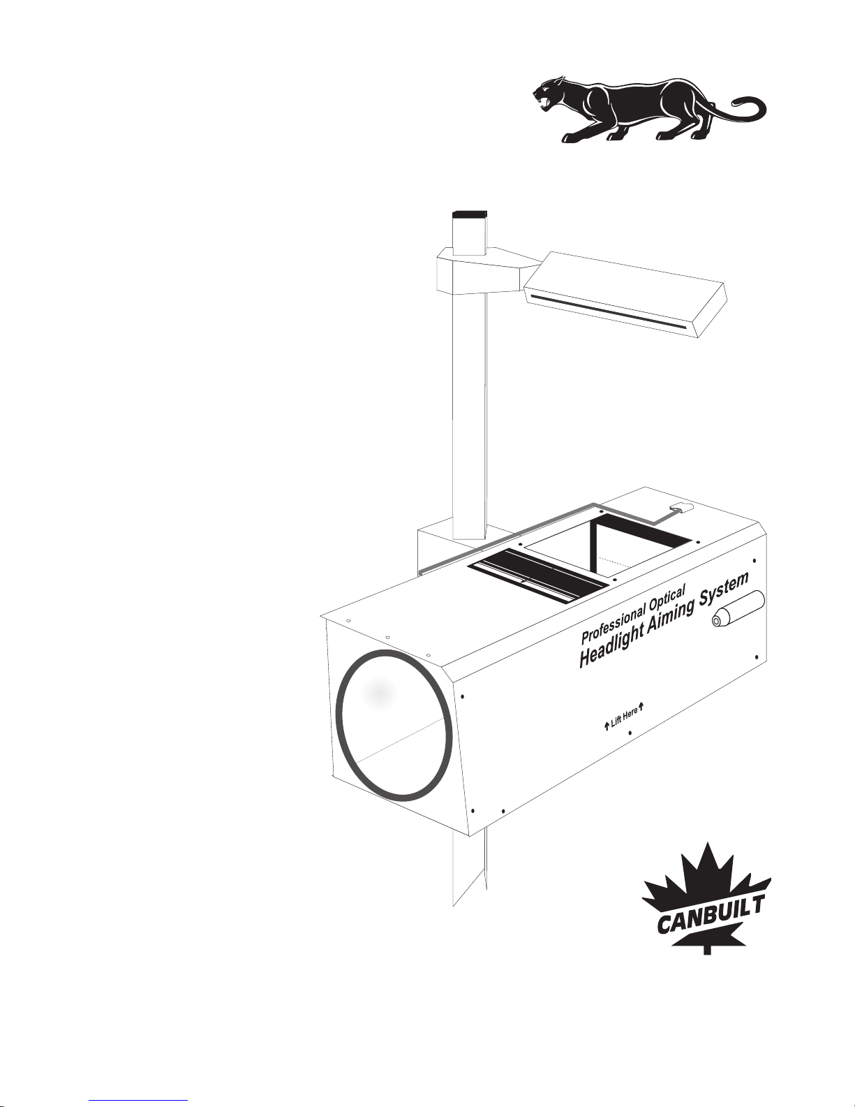
Model OPT-5405
Ver 050720
Professional
Optical Headlight Aiming System
Canbuilt Mfg.
Perfect Night Vision.....
Page 2

Page 3

Index
INDEX
Aiming Low Beams 14
Aiming High Beam and Auxiliary Lights 17
Aiming Fog Lights 18
Aiming European Beam 19
Forewords 3
Assembling the aimer 4
Calibrating the Floor 7
Floor Slope Register 8
Vehicle Preparations 9
Positioning Aimer to Vehicle 10
Beam Slope Compensation 20
Calibrating the aimer 21
Warranty Information 27
Aiming Procedures 12
The Aiming Screen 12
Beam Elucidation Filters 13
Canbuilt Mfg.
103 Milvan Dr.
Toronto, Ontario
Canada M9L 1Z7
(416) 749-6555
www.canbuilt.com
Index - Page 1
Canbuilt Mfg.
Perfect Night Vision.....
Page 4

Page 5

THE PANTHER OPTICAL HEADLIGHT AIMER MODEL OPT-5405
Thank you for purchasingthe OPT-5405 Optical Headlight Aimer.Panther
You have made a wise purchase decision. The OPT-5405 is a high quality, durable piece
of equipment that will give you years of troublefree operation.
Your aimerhasover25 years of engineering refinementbuilt-in. It is designed to meet the
following requirements:
Designed for compliance with the latest revisions of the Standards SAE J599 (Aug 1997)
and J600 (Feb 1993).
Aims all headlights including Domestic, European,andAsian type headlights.
Laser guided floor slope compensation.
Simple operation.
Easily transportable frombaytobay.
Requiresnofloortrack.
Built-in self-checking for orthogonality of its components.
The aiming is performed based on an image of the headlight beam recreated inside the
optical aimer head. The internal screen duplicates the screen required by the SAE
standardJ599.
This manual is written based on the requirements of the SAE J599 standard for headlight
aim.
Forewords
Forewords-Page 3
Canbuilt Mfg.
Perfect Night Vision.....
Page 6
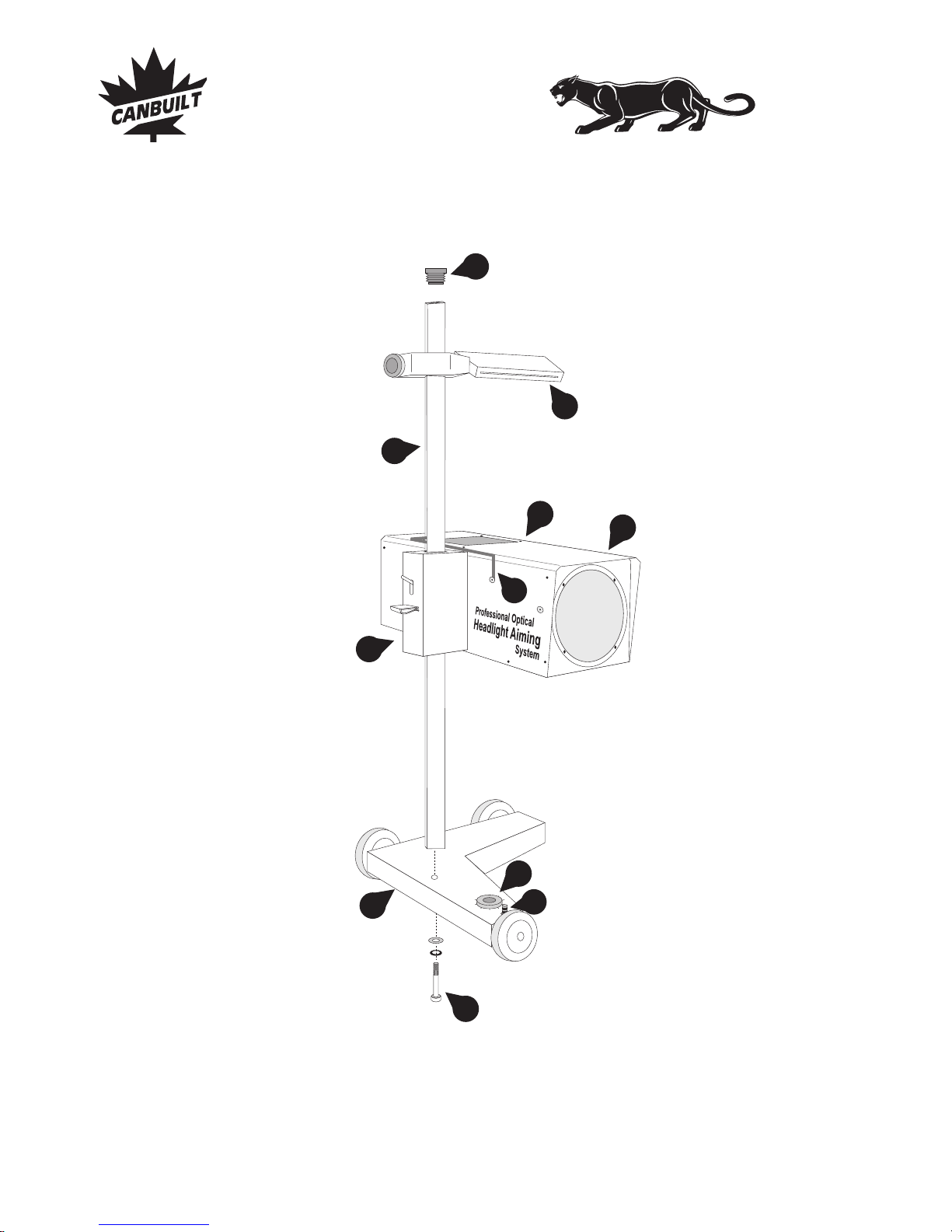
COMPONENTS:
1
2
3
4
5
6
. Optical aimer head
. Heavy-duty mast
. Reinforced base with wheels
. Hardware to attach the mast to the
base:
1 Bolt DIN 912, M 10 x 50
1 Washer DIN 7980, 10 mm
1 Flat washer, 10 mm
. Lateral alignment visor
. Lock / unlock mechanism
. Mast cap
. Precision floor slope compensation
system
7
8
9
10
11.
. Aimer positioning system
. Floor slope register
Laser guided floor slope
measurement system (not shown)
3
5
1
2
7
4
8
0
9
8
7
6
5
4
3
2
1
10
Assembling the Aimer
6
9
11
Page 4 - Assembling the Aimer
Canbuilt Mfg.
Perfect Night Vision.....
Page 7
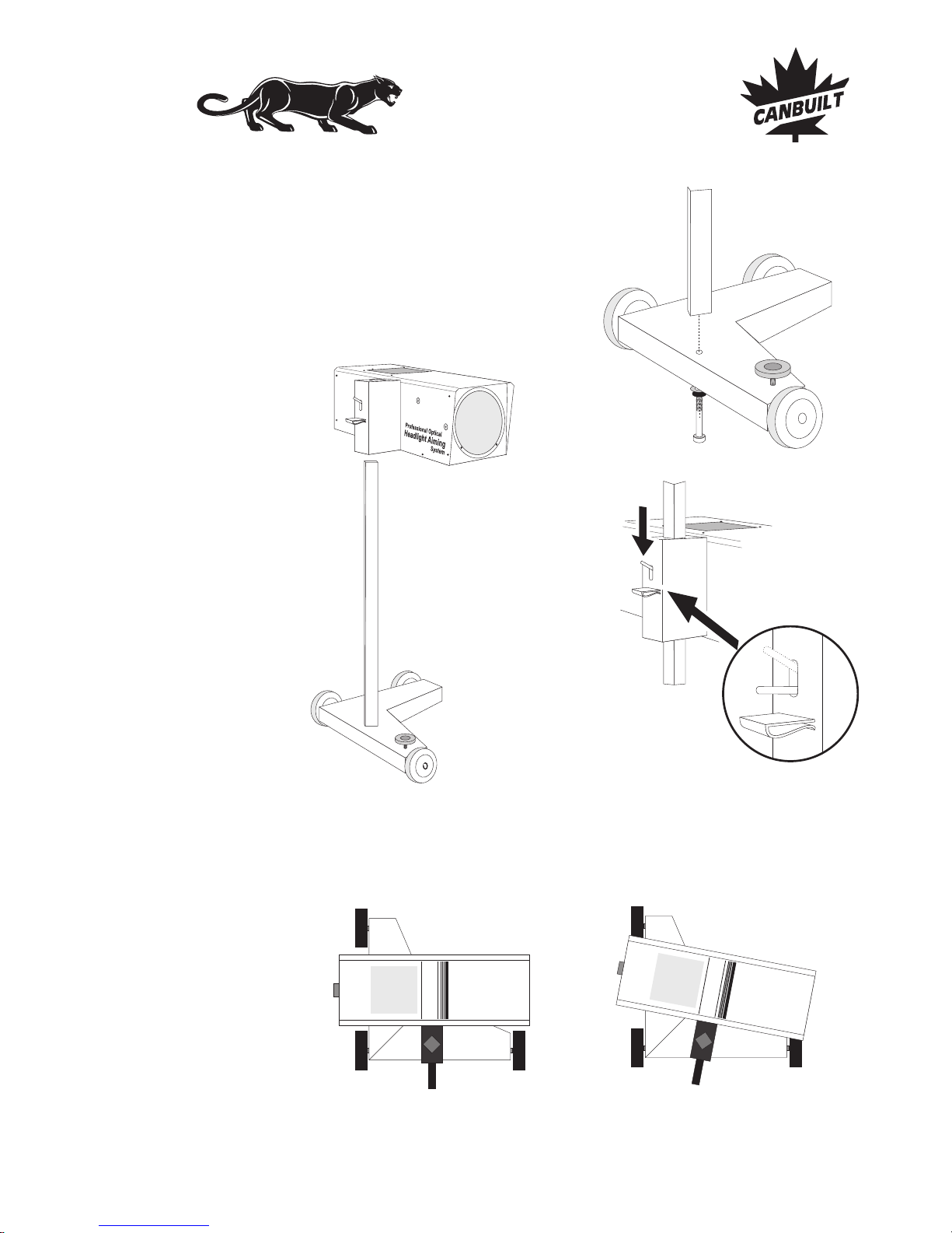
Assembling the Aimer
STEP 1
Bolt the mast to the base aligning the mast as shown in
fig. 1.
STEP 2
Install optical aimer head on
mast as shown in fig.2 by
pressing trigger lock (fig. 3)
and sliding it down the mast.
Fig. 1
STEP 3
Check that the mast is correctly positioned. The aimer head should be parallel to the
base (fig. 4). Tighten the mast bolt with 10 mm allen wrench.
Fig. 4
CORRECT
INCORRECT
Fig. 2
Fig. 3
Assembling the Aimer - Page 5
Canbuilt Mfg.
Perfect Night Vision.....
Page 8
Assembling the Aimer
ASSEMBLY IS COMPLETE
The Panther is factory calibrated for accuracy, to verify calibration of aimer, see section
on aimer calibration.
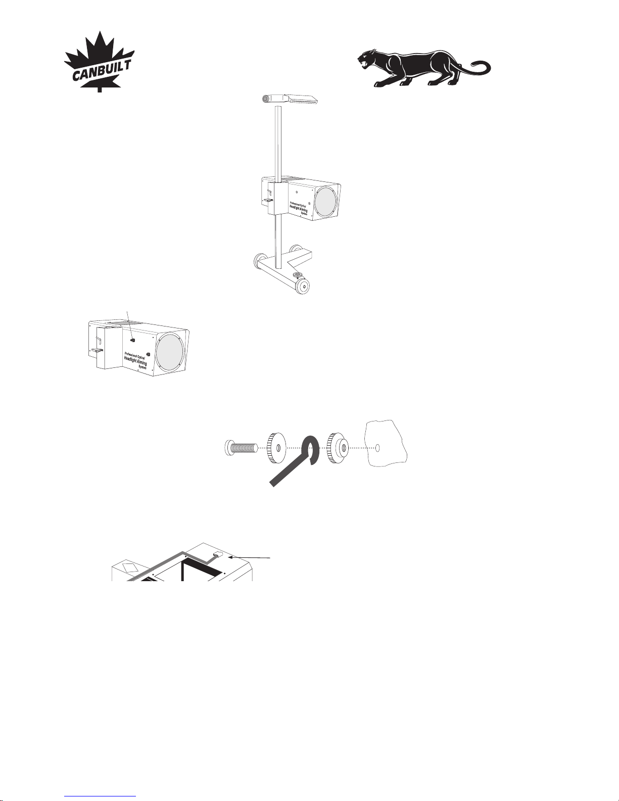
Attach the holder to the middle of
the aimer head, at the tip of the
pointer.
Fig. 5
STEP 4
Install the lateral alignment visor (fig. 5). The
narrow slot in the visor should face the rear of the
aimer (the wide slot faces the front).
STEP 5
Install the pointer positioning system using
hardware as shown in fig. 7. Hardware is attached
to the optical aimer head and must be removed for
pointer installation fig.6.
fig. 6
Hardware for Pointer
Positioning System
Thread nut on bolt , insert
through eye in pointer system and
thread nut on bolt . Install
assembly on optical aimer head
tightening nut against aimer as
shown in fig. 7.
Repeat the processforstopperpin.
BA
CA
C
fig. 8
Page 6 - Assembling the Aimer
fig. 7
CB
A
pointer system
Canbuilt Mfg.
Perfect Night Vision.....
Page 9
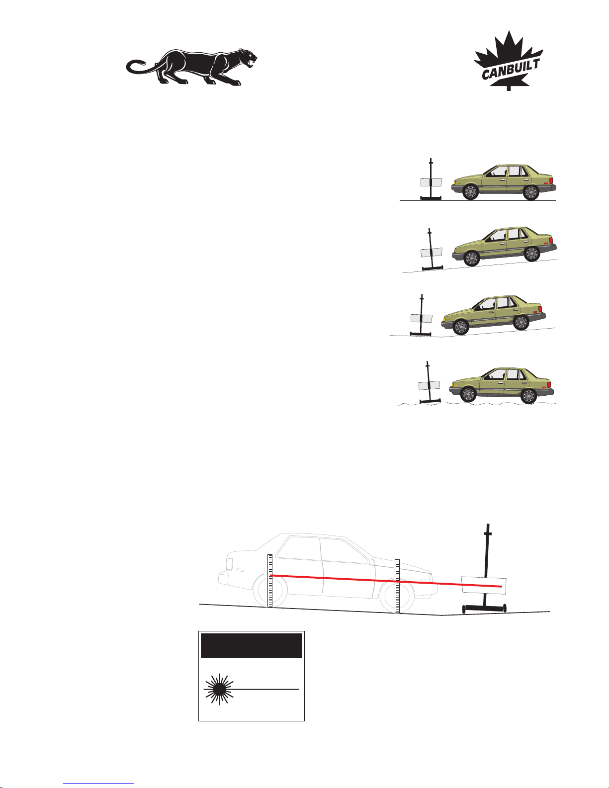
Calibrating the Floor
INITIAL FLOOR SLOPE COMPENSATION
Vehicle and aimer are both located
on a flat andlevel floor.
Floor compensation is required.
Fig. 12
Vehicle and aimer are both located
on a flat floor with a constant slope.
Floor compensation is required.
Fig. 13
Vehicle and aimer are located on
different flats, both of them with a
constant slope.
Floor compensation is required.
Fig. 14
Vehicle and/or aimer are located on
irregular flats.
It is recommended not to aim the
headlamps on such floors.
Fig. 15
LASER GUIDED FLOOR SLOPE COMPENSATION SYSTEM
Position aimer at front of bay. Turn on laser by turning knob on laser housing. Measure
center of laser beam height from floor at front wheel and at back wheel. The distance
from the floor should be the same. If it is not, adjust floor slope knob until they are equal.
See fig. 16 and fig. 19.
Fig. 16
CAUTION
LASER RADIATION
DO NOT STARE
INTO BEAM
CLASS II LASER PRODUCT
POWER OUTPUT < 1mW
WAVELENGHT: 630-680 nm
Calibrating the floor - Page 7
Canbuilt Mfg.
Perfect Night Vision.....
Page 10
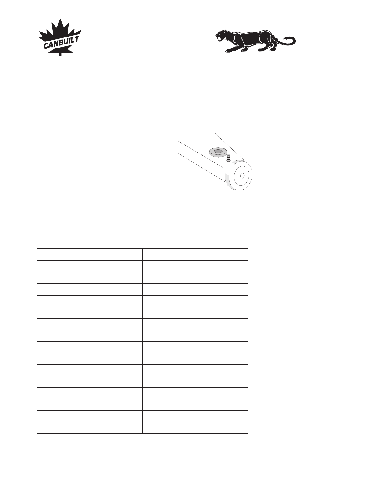
Calibrating the Floor
0
9
8
7
6
5
4
3
2
1
Floor slope adjustment knob
Fig. 19
RECORDING THE FLOOR SLOPE SETTING
Near the floor slope adjustment knob , there is a
register consisting of a small cylinder that can be
used to count the turns of the knob . This register
sinks or raises with each turn of the knob (fig. 19).
Shops using the aimer in more than one location
should record the floor slope settings for each
location.
.
Use the recorded floor slope setting for subsequent
uses in the same location. Simply set the slope
adjustment knob to the previously recorded position
prior to aiming headlights.
ONCE THE SETTING IS RECORDED, IT IS NOT
NECESSARY TO TAKE THE FLOOR SLOPE
MEASUREMENT AGAIN FOR THIS LOCATION
Note: A decal is included with the aimer. You can record floor slope settings and adhere
the decal to aimer for reference. You can also use the matrix below for recording this
information.
BAY NUMBER
REGISTER SETTING
REGISTER SETTING KNOB SETTINGKNOB SETTING
DATE
Page 8 - Floor slope register
Canbuilt Mfg.
Perfect Night Vision.....
Page 11

PREPARING THE VEHICLE FOR HEADLAMP AIM OR INSPECTION
Beforecheckingtheaim,theinspectorshall;
Remove ice or mud fromunderfenders.
Set tire inflation pressures to the values specified on the tire sidewall or
information label.
Check car springs for sag or brokenleaves.
See that thereisnoloadinthevehicleotherthanthedriver.
Check functioning of any automatic vehicle leveling systems and specific
manufacturer's instructions pertaining to vehicle preparation for headlamp
aiming.
Clean lenses.
Check for bulb burnout, brokenaimingpads,andproper beam switching.
Stabilize suspension by rocking vehicle sideways.
Measuretheverticalheightofthecenteroftheheadlampfrom the ground.
F
F
F
F
F
F
F
F
F
Vehicle Preparations
Vehicle Preparations - Page 9
Canbuilt Mfg.
Perfect Night Vision.....
Page 12
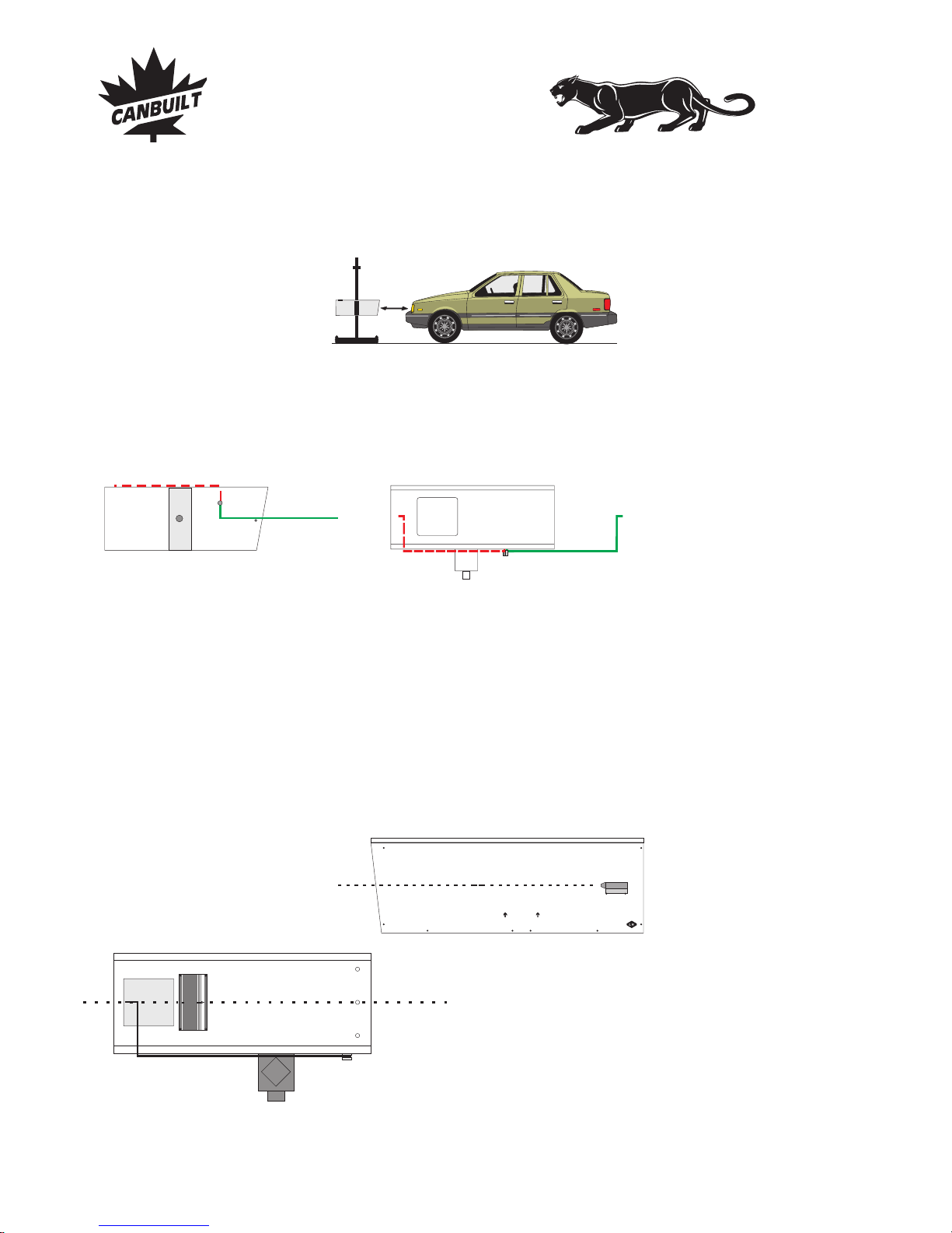
Positioning the Aimer to Vehicle
POSITIONING THE AIMER TO VEHICLE
25-35 cm
10-14 in
Fig. 20
Top View
Side view
Note: There are several ways to determine the center of the headlight beam. If your
headlight has a clear lens and you can see the bulb, it is generally located at the center.
Some headlight lenses have a small dot in the lens that indicates the center. Many light
beams have a “dark spot” in the center of the beam, this can be easily found by placing a
cloth over the light and turning on the headlights.
Rotate aimer positioning system (pointer) to front of aimer. Move aimer so that
positioning pointer is at center of headlight beam. The pointer can be stored as shown
with dashed lines in illustration, when not in use.
Canbuilt
Lift Here
Professional Optical
Headlight Aiming System
Align with center of beam
Align with center of beam
Place the aimer in front of one
headlamp at a distance between 10
to 14 in. (25 to 35 cm). Mos t beam
patterns are clearest if the optical
lens is about 12” from the lamp
surface.
OPTIONAL METHOD OF POSITIONING AIMER
The has markings drawnon the aimer which can also be used for positioning the
aimer at the center of the headlight. These markings can be used instead of the pointer if
desired. Laser can also be used for vertical centering. See drawingsbelow.
Panther
Page 10 - Positioning Aimer to Vehicle
Canbuilt Mfg.
Perfect Night Vision.....
Page 13
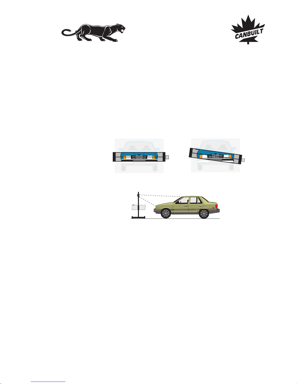
CORRECT
INCORRECT
CORRECT
INCORRECT
Fig. 21
Aligning Aimer to Vehicle
POSITIONING AIMER TO VEHICLE
With the aimer centered in front of the vehicle, choose two symmetrical points of the
vehicle located at the same height off the ground (i.e. the upper part of the lamps, strut
bolts, radiator support bolts, grill work etc.).
Points located too
high, such as the vehicle roof, should be avoided: the best accuracy is
obtained using lower points.
Make sure that plenty of light is on the front of the vehicle. Looking through
the lateral
alignment visor, spot the two points and position both points on the visor's wire, by
slightly rotating the aimer left or right, Fig.21.
Aimer is ready to test headlight. Turn on headlights and use internal screen to aim the
light. Correct beam positioning on the aimingscreen is explained on the following pages.
Proper aim for high beams, low beams, Euro beams, driving lights, and fog lights are
explained.
Positioning Aimer to Vehicle - Page 11
Canbuilt Mfg.
Perfect Night Vision.....
Page 14
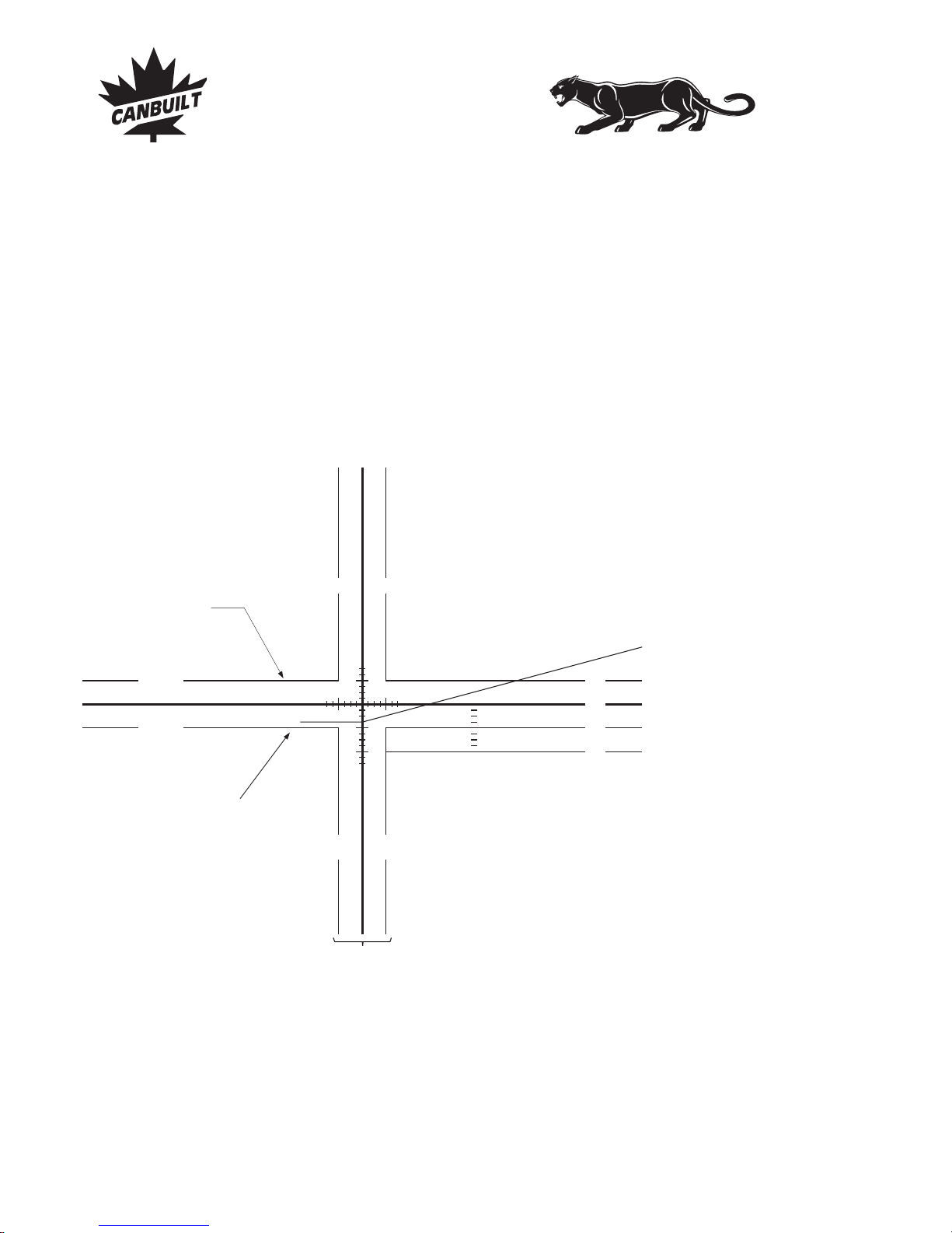
Aiming Procedures
Horizontal line used as low beam
inspection upper limit.
Horizontal line used as low
beam inspection lower limit.
Biased line for the
European type low beam
Two vertical lines used as low
beam lateral inspection limits.
Illustrations on the following pages show more detail for specific types of lamps.
100 mm
100 mm
100mm100
mm
4"
4"
4"
0"
4"
8"
DESCRIPTION OF THE INTERNAL SCREEN OF THE AIMER
The Panther 5405 is designed to reproduce, at a smaller scale, an aiming test screen
compliant with the Standard SAEJ599 (revised Aug. 1997). The beam projections appear
on the internal screen of the aimer as they would appear on a screen located 25 feet from
the headlamps.
The aiming screen complies with all aiming and inspection requirements of the Standards
SAE J599 (revisedAugust 1997) and SAE J600 (revised February 1993).
Withthe linesdrawn onthe internal screen of the aimer, all aiming and testing procedures
can be performed .
In addition, the Europeantype lightingcan also be aimed.
accordingto theinspection limits described in the Standards
Page 12 - Aiming Procedures - The Aiming Screen
Canbuilt Mfg.
Perfect Night Vision.....
Page 15
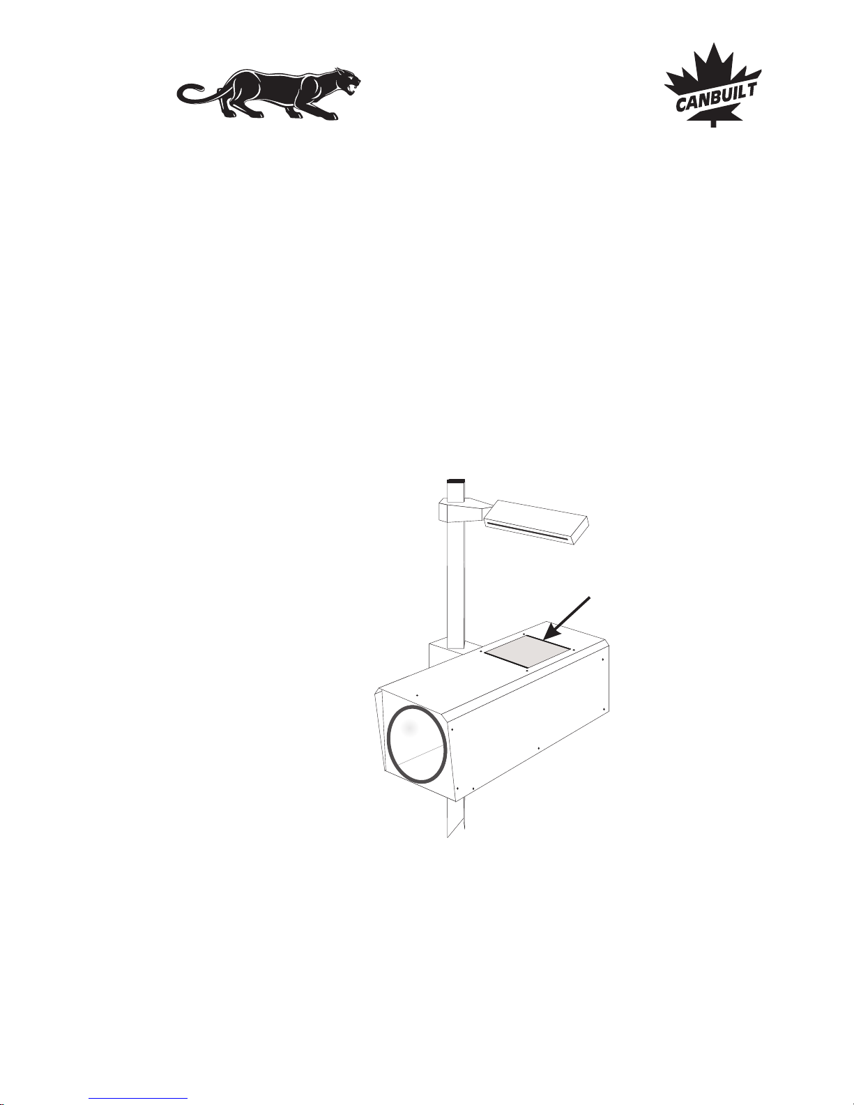
BEAM ELUCIDATION FILTERS
Due to the widely varying light and of automotive headlights, and
different operators sensitivity to light, it is difficult to locate the light beam pattern when
adjusting headlights on somevehicles. Canbuilt has developed abeam elucidation filter
to make it easier to view these beam patterns. The filters are designed to remove some of
the extraneous light from the viewable pattern and enhance the high intensity zone,
providing an image that is clearer and easierto see.
To use the filter, simply set it on top of the aimer body above the viewing window. The
magnetic strips will hold it in place. For best operation, the magnetic strips should be
toward the front and rear of the aimer.
The filters can be stored by using the magnetic strips to attach them any place on the
metal aimer head.
intensity color
Choose the filter (or filters) that works best for
your vision.
Place filter over viewing
window here
Aiming Procedures - Beam Elucidation Filters - Page 13
Aiming Procedures
Canbuilt Mfg.
Perfect Night Vision.....
Page 16
Aiming Procedures
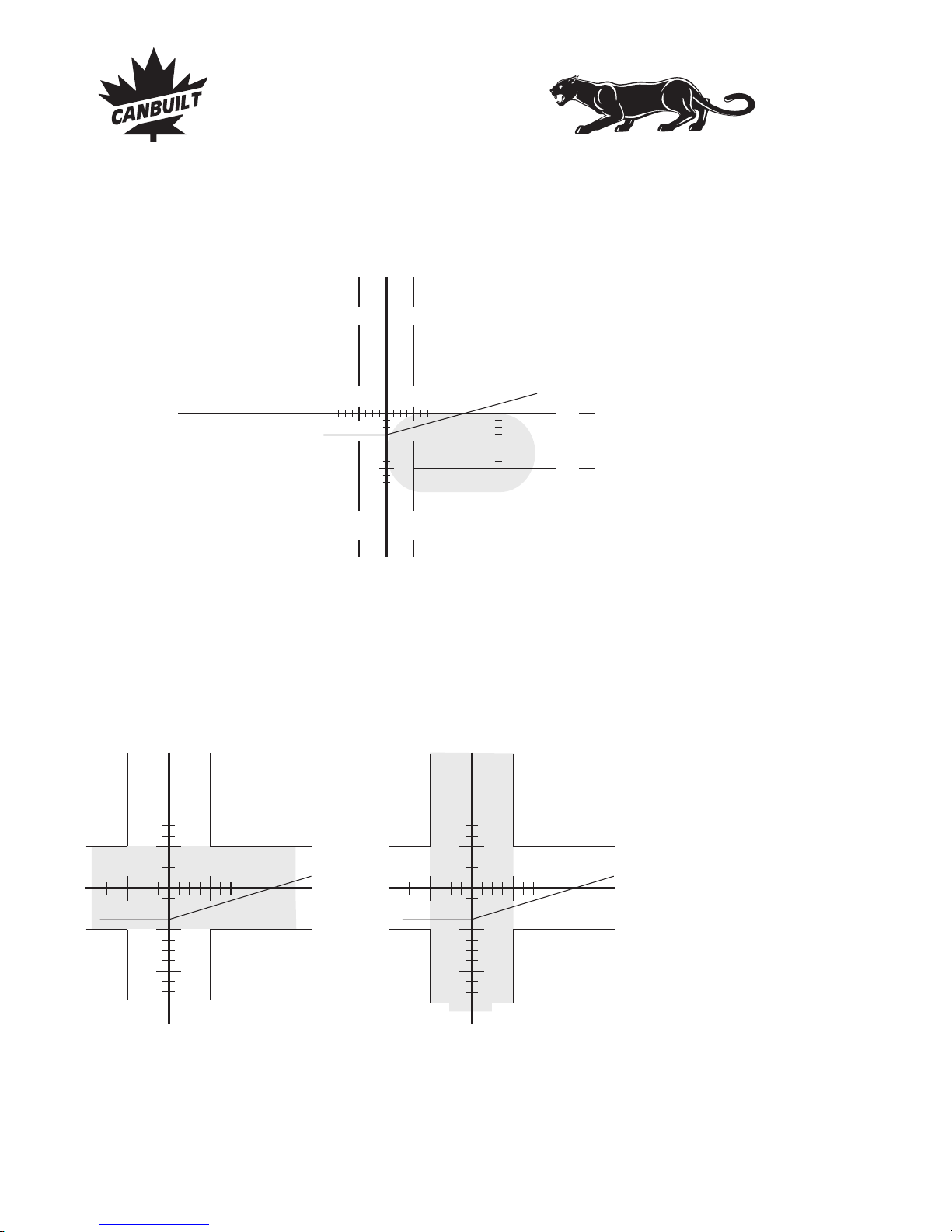
INSPECTION LIMITS FOR LOW BEAM HEADLIGHTS
The inspection limits are a range of 4” at 25’. The illustrations below show the range
allowed for vertical and horizontal inspection.
The left side of the “high intensity zone” must fall
within the shaded area for proper low beam
horizontal adjustment.
The top of the “highintensity zone” must fall within
the shaded area for proper low beam vertical
adjustment.
Nominal Vertical Aim Line
100 mm
100 mm
100
mm
100
mm
4"
4"
4"
0"
4"
8"
Inspection
upper limit
Inspection
lower limit
4"
0"
4"
4" 4"
Inspection
left limit
Inspection
right limit
4"
0"
4"
4" 4"
AIMING LOW BEAM HEADLAMPS
Low Beam Headlamps are aimed so that the top edge of the high-intensity zone is at the
line, and the left edge of the high-intensity zone is at the
vertical center line of the screen.
NOMINAL VERTICAL AIM
NOTE: Headlights centered more than 36” from the ground require beam slope
compensation. See page 18 for details.
Page 13 - Aiming Procedures - Aiming Low Beams
Canbuilt Mfg.
Perfect Night Vision.....
Page 17
Aiming Procedures
4"
0"
4"
4" 4"
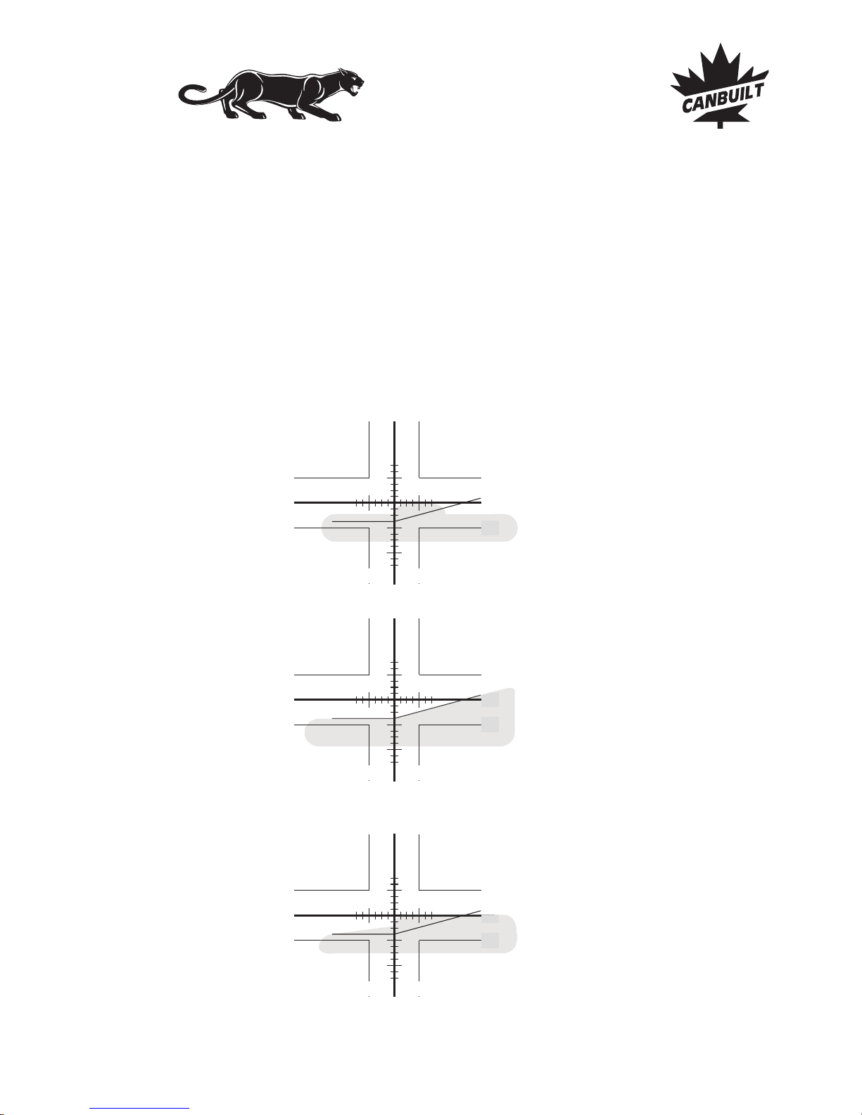
Many composite headlights do not have a
distinct “high intensity zone”. When
adjusting these lights you must locate the
area in the beam pattern that rises above
the rest of thebeam. This partof the pattern
shines farthest down the road and is
consideredthe “highintensity zone”.
Many late model headlights have patterns
similar to the European beam pattern. You
should set these headlights using the
biased line as shown.
Some patterns do not have a distinct edge
on the right side. When aiming this type of
headlight, ignore the right side of the
pattern. Simply locate the left edge of the
high intensity area that shines farthest
down the road. This should be adjusted to
the centerline on the aiming screen. The
top edge will normally be easy to locate.
DIFFERENT LOW BEAM PATTERNS
is highest on the screen)
There are many different beam patterns used in domestic vehicles. When checking
headlights with complicated beam patterns, you must locate the part of the high intensity
zone that shines farthest down the road ( . This generally appears
as a “hump” in the beam pattern. Once this is located, you simply set the left edge of the
“hump” to align with the center cross hair on the screen. You set the top of the “hump”
with the horizontal cross hair. The bottom of the “hump” typically blends into the lower
portion of the beam pattern and is not consideredwhen adjustingthe headlight.
Sample patterns can be seen Beam Pattern Book
0
4"
4"
0"
4"
4" 4"
4"
0"
4"
4" 4"
0"
4"
0
4"
Aiming Procedures - Aiming Low Beams - Page 14
Canbuilt Mfg.
Perfect Night Vision.....
Page 18
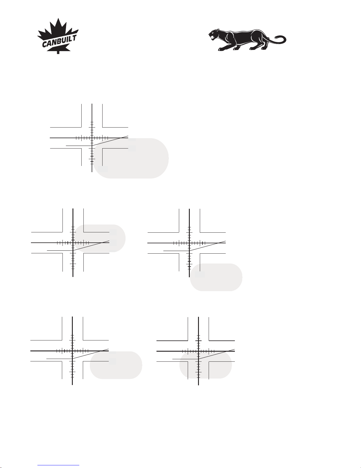
Aiming Procedures
INSPECTION LIMITS FOR LOW BEAM HEADLIGHTS
4"
0"
4"
4" 4"
FAIL, too far right
0
4"
FAIL, too high
4"
0"
4"
4" 4"
4"
0"
FAIL, too far left
4"
0"
4"
4" 4"
Perfect
Adjustment
FAIL, too low
4"
0"
4"
4" 4"
4"
4"
0"
4"
4" 4"
0
4"
4"
Page 15 - Aiming Procedures - Aiming Low Beams
Canbuilt Mfg.
Perfect Night Vision.....
Page 19
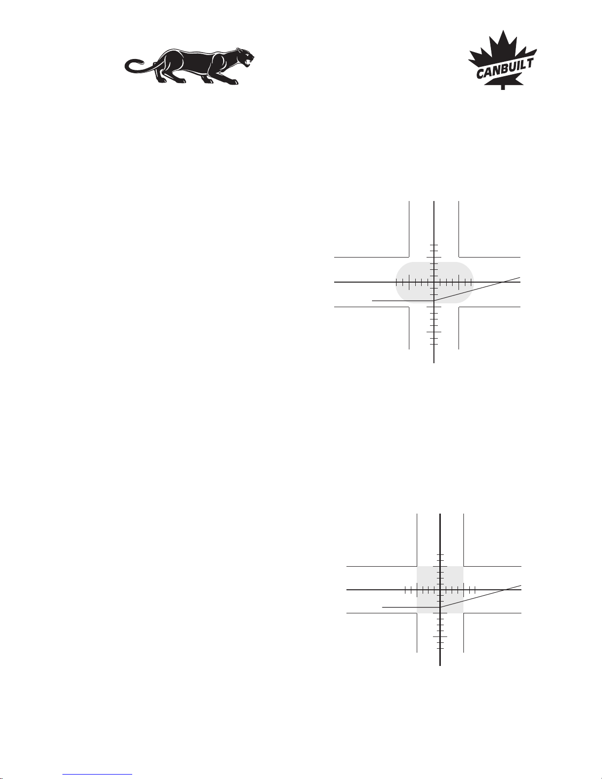
AIMING HIGH BEAM HEADLAMPS AND AUXILIARY DRIVING LIGHTS
High beam headlamps and auxiliary driving lightsare aimed so that the center of thehighintensity zone is located at the horizontal and vertical center of the screen.
Aiming Procedures
INSPECTION LIMITS FOR HIGH BEAM HEADLAMPS AND
AUXILIARY DRIVING LIGHTS
The inspection limits for high-beam headlamps shall be with the center of the highintensity zone from 100mm (4") up, to 100mm (4") down; and, from 100mm (4") left to
100mm (4") right on a screenat 7.6m(25').
4"
0"
4"
4" 4"
The figure shows the high-intensity
zone (shaded area) of a properly
aimed on the aiming
screen.
HIGH BEAM
Inspection limits (shaded area) for
the center of the high-intensity zone
of headlamps and
auxiliary driving lamps.
HIGH BEAM
4"
0"
4"
4" 4"
Aiming Procedures - High Beam and Auxiliary Lights - Page 16
Canbuilt Mfg.
Perfect Night Vision.....
Page 20
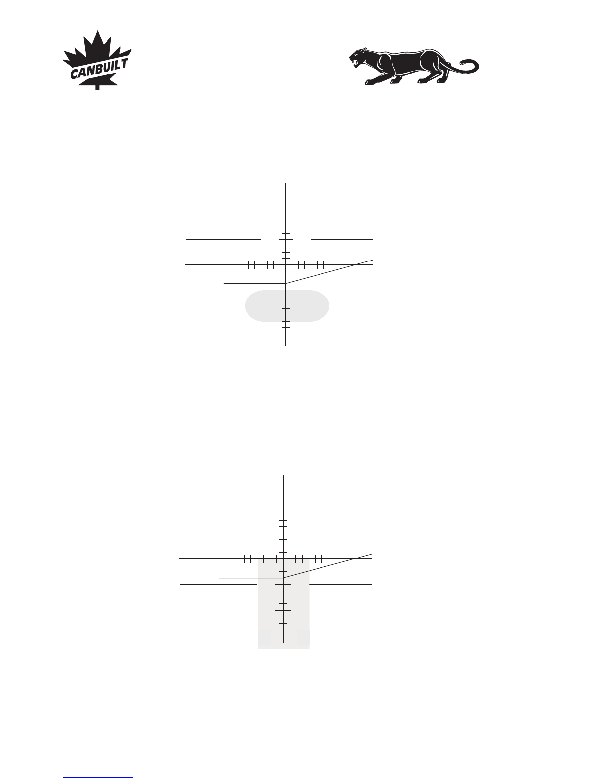
Aiming Procedures
INSPECTION LIMITS FOR FOGLAMPS
The inspection limits for symmetrical fog lamps installed with universal mounting
applications, shall be with the top edge of the high-intensity zone at horizontal or below
and with thecenter of the high-intensity zone from 100 mm (4") left to 100mm (4") right on
a viewing screenlocated at7.6m (25') from the vehicle.
Inspection limits (shaded area) for
the top edge and center of the highintensity zone of .FOG LAMPS
AIMING FOG LAMPS
The correct aim for fog lamps with symmetrical beams (as described in SAE J583) is with
the top edge of the high-intensity zone at or below the horizontal centerline and the center
of the high-intensity zone centeredon thescreen.
The figure shows (shaded area
indicates high-intensity zone) a
properly aimed symmetrical
on the aiming screen.
FOG
LAMP BEAM
4"
0"
4"
4" 4"
4"
0"
4"
4" 4"
"
4
Page 17 - Aiming Procedures - Fog Lights
Canbuilt Mfg.
Perfect Night Vision.....
Page 21
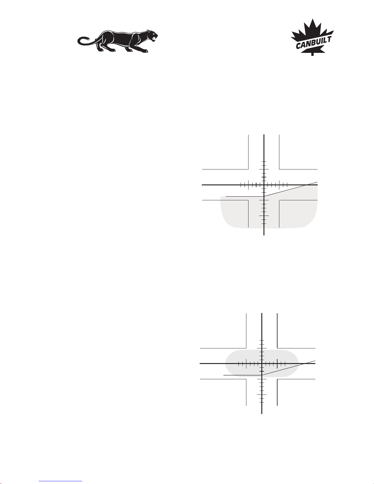
Aiming Procedures
AIMING EUROPEAN LOW BEAM HEADLAMPS
European low beams do not have a high-intensity zone, all the illuminated area has a
similar intensity.
European type low beams are aimed so the cutoff of the illuminated zone is located at the
horizontal and biased line.
AIMING EUROPEAN HIGH BEAM HEADLAMPS
European high beams are aimed so that the high-intensity zone is centered on the
horizontal and vertical center lines.
4"
0"
4"
4"4"
4"
0"
4"
4" 4"
Aiming Procedures - European Beam - Page 18
Canbuilt Mfg.
Perfect Night Vision.....
Page 22
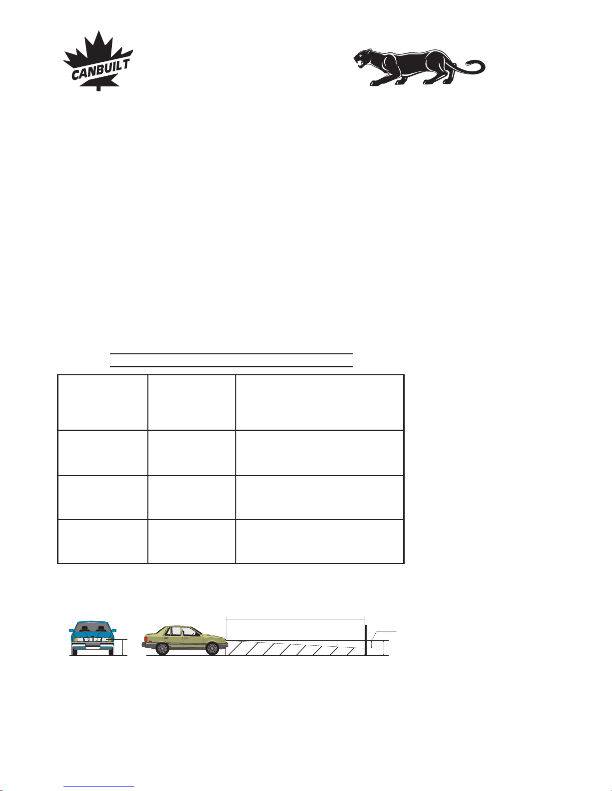
BEAM SLOPE COMPENSATION
NOMINAL VERTICAL AIM FOR LOW BEAMS
The revised SAE J599 standard (8/97) requires low beam headlight aim to be adjusted
based on headlamp height from the ground. The NOMINAL VERTICAL AIM position on
low beam headlamps, as introduced in the new revision of the Standard SAE J599, "shall
be adjusted based on the headlamp mounting height, from the ground to the light source
center of the headlamp".
The TABLE 1 shows the VERTICAL BEAM AIM GUIDELINES as required in the
standard.These applyonly for low beam.
The states that headlights centered 36”- 48” from the ground must be aimed 2”
below the 0 line and headlights mounted 48”- 54” must be aimed 4” below the 0 line.
Inspection tolerance is plus or minus 4”.
TABLE
7.6 m (25 ft)
H
Nominal
Vertical
Aim
Headlamp centerline
mounting height
H
Beam Slope Compensation
TABLE 1 - VERTICAL AIM GUIDELINES
Headlamp
(centerline) Aim Inspection Limits
mounting for Vertical Aim
height
22
to
36 in
0
4in
UP to
4in
DOWN
36
to
48 in 2 in
DOWN
2in
UP to
6in
DOWN
48
to
54 in 4 in
DOWN
0in
UP to
8in
DOWN
56 90 cm 100 mm 100mm
90 120 cm 50 mm 50 mm 150 mm
120 140 cm 100 mm 0 mm 200mm
Beam slope
compensation
(nominal
vertical aim)
Page 19 - Beam Slope Compensation - Nominal Vertical Aim
Canbuilt Mfg.
Perfect Night Vision.....
Page 23
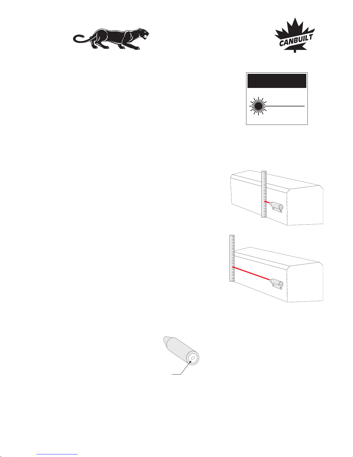
Calibrating the Aimer
CHECKING CALIBRATION
OF THE LASER
Use a ruler with increments of at least 1/16"
(or 1 mm) to determine that the laser beam
height from the bottom is the same at the
laser pointer and at the front of the aimer
head, see fig. 27 and fig. 28.
REPLACING BATTERY IN LASER
To change laser batteries, remove the cap of
the laser pointer as shown in figurebelow.
Use threestandard batteries type LR44 1.5V.
Turn the laser on and measure the height of
the beam from the bottom of theoptical aimer
head, as shown.
Move the ruler to the end of the optical aimer
head to see if the height of the beam is the
same.
If there is any deviation, loosen the mounting
screwsand adjustas needed.
Tighten mounting screws and repeat the
measurement to ensure that the laser has not
moved when tightening.
Extract batteries
removing this cap
fig. 27
fig. 28
CAUTION
LASER RADIATION
DO NOT STARE
INTO BEAM
CLASS II LASER PRODUCT
POWER OUTPUT < 1mW
WAVELENGHT: 630-680 nm
Calibrating the Aimer - Page 20
Canbuilt Mfg.
Perfect Night Vision.....
Page 24
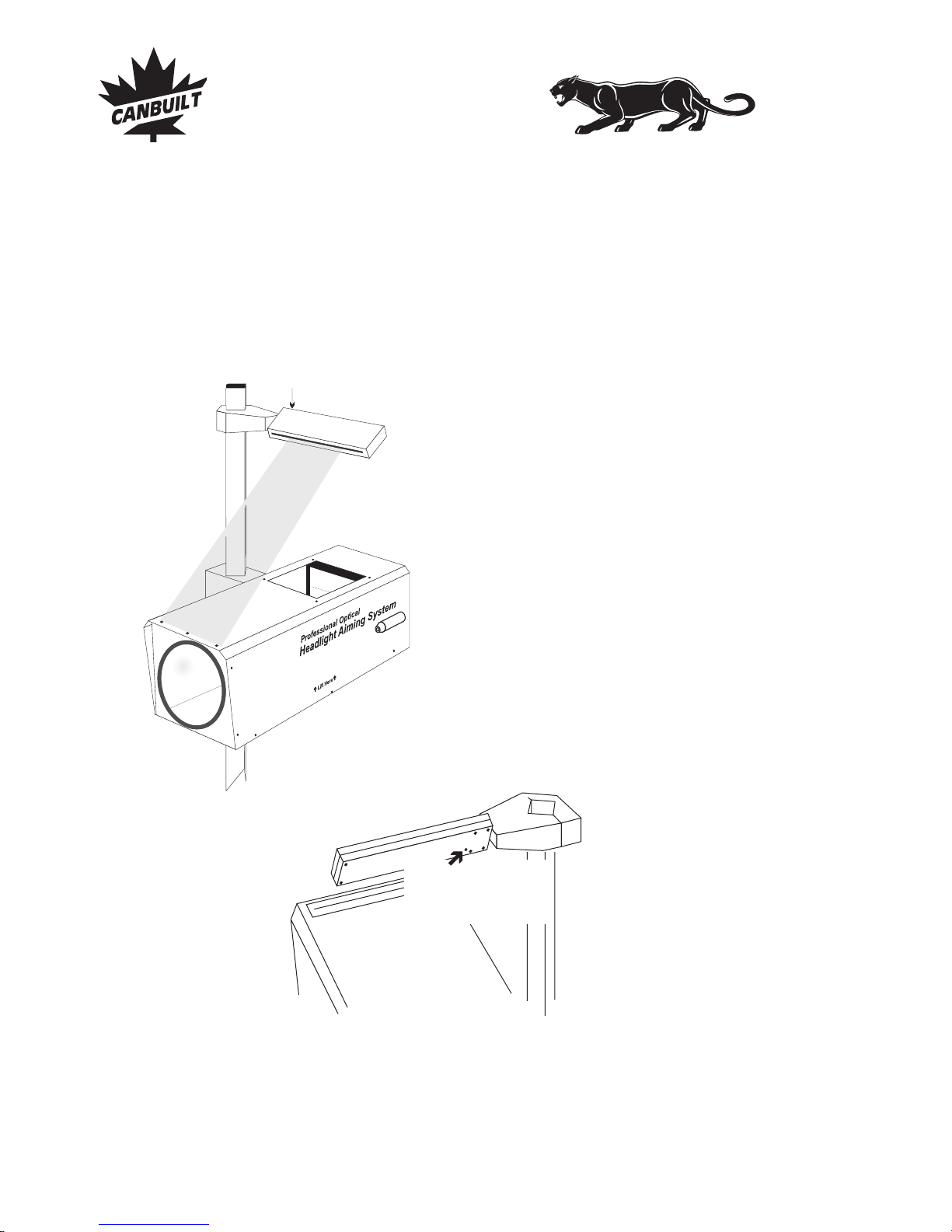
Calibrating the Aimer
Adjust the visor
line here below
CHECKING THE LATERAL ALIGNMENT VISOR
Check calibration of the visor by looking through the visor at the lateral calibration
points on the aimerhead asshown in drawings below. Theline inthe visor must match the
edge of the three aligned holes on the aimer head. Ifthe visor is not perfectly aligned, turn
the small allen (1.5 mm) screwat thebottom of the visor until the lines match.
Adjust the
visor line here
Page 21 - Calibrating the Aimer
Canbuilt Mfg.
Perfect Night Vision.....
Page 25
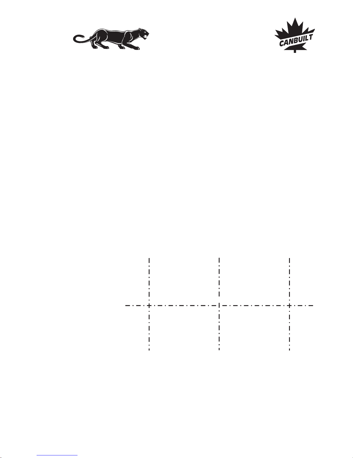
CALIBRATING THE SCREEN
To check the aimer for accuracy, place a car in front of a screen or aflat vertical wall, at a
distance of 25 feet (7.6m).
Traceor mark with tape the lines as shown in the figure below.
If the headlamp mounting height of the vehicle used for the test is more than 36in, then a
Nominal Vertical Aim line at the distance specified in the Table 1shall betraced.
Perform the preparationfor headlampaim as detailed.
Proceedto aimthe lower beam as explained in next page.
VERTICAL CENTERLINE
AHEAD OF LEFT
HEADLAMP
VERTICAL CENTERLINE
AHEAD OF RIGHT
HEADLAMP
CAR AXIS
SCREEN MARKING
HEIGHT OF LAMP CENTERS
Calibrating the Aimer
Calibrating the Aimer - Page 22
Canbuilt Mfg.
Perfect Night Vision.....
Page 26
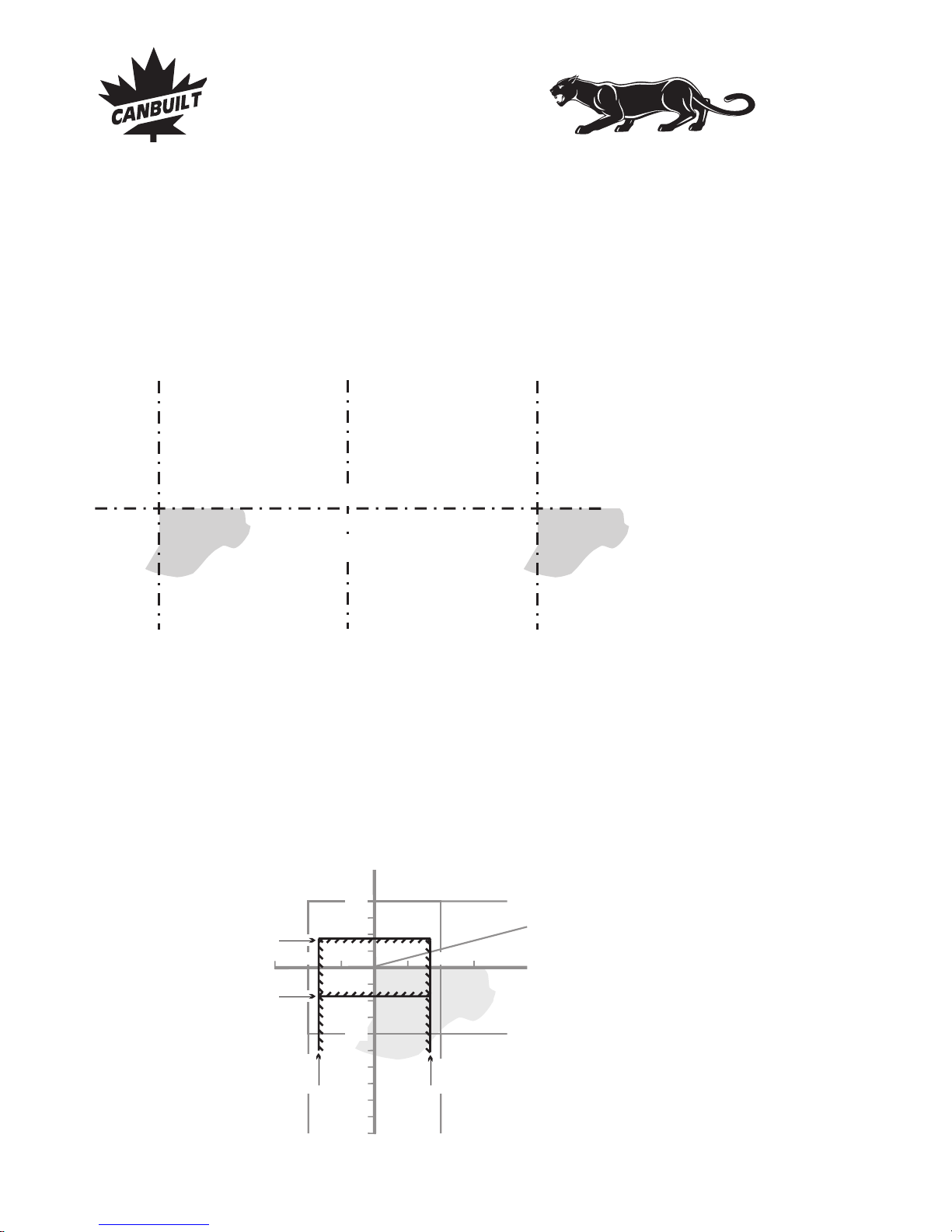
CHECKING THE AIMER
Once the beam is aligned, place the aimer in front of one of the lights, as described in the
instructions, and check if the projectionof thebeam on the internal screen is the same.
Following tolerances areallowed:
TOLERANCES
The Standard SAE J600 allows a tolerance of ±0.3º (±1.6 in, or ±40mm) for the vertical
aim, and ±0.6º (±3.2 in, or ±80mm) for the horizontal.
The tolerance limits areshown inthe figure below.
HIGH-INTENSITY ZONE (SHADED AREA) OF A PROPERLYAIMED
ON THE AIMING SCREEN IN FRONT OF VEHICLELOWER BEAM
VERTICAL CENTERLINE
AHEAD OF LEFT
HEADLAMP
VERTICAL CENTERLINE
AHEAD OF RIGHT
HEADLAMP
CAR AXIS
AIMING the LOWER BEAM
HEIGHT OF LAMP CENTERS
OR NOMINAL VERTICALAIM
(SEE TABLE 1)
AIMING LOW BEAM HEADLAMPS
Aim Low Beam Headlamps so that the top edge (the cutoff) of the high-intensity zone is at
the NOMINAL VERTICAL AIM line, and the left edge of the high-intensity zone is at the
vertical centerline of the headlamp.
100100
100
100
200
Upper tolerance for
the upper edge
Lower tolerance for
the upper edge
Right tolerance
for the left edge
Left tolerance
for the left edge
Calibrating the Aimer
Page 23 - Calibrating the Aimer
Canbuilt Mfg.
Perfect Night Vision.....
Page 27
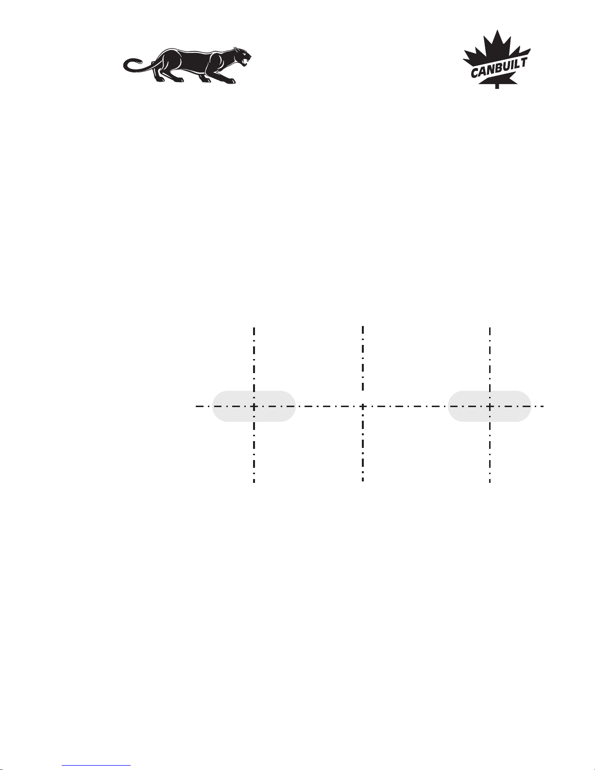
VERTICAL CENTERLINE
AHEAD OF LEFT
HEADLAMP
VERTICAL CENTERLINE
AHEAD OF RIGHT
HEADLAMP
CAR AXIS
HEIGHT OF LAMP CENTERS
HIGH-INTENSITY ZONE (SHADED AREA) OF A PROPERLYAIMED
ON THE AIMING SCREEN IN FRONT OF VEHICLEUPPER BEAM
AIMING the UPPER BEAM
ALTERNATIVE PROCEDURE
The same procedure may be done by checking theaimer using the high beam instead of the
low as a reference.
AIMING HIGH BEAM HEADLAMPS
High beam headlamps and auxiliary driving lightsare aimed so that the center of thehighintensity zone is located at the horizontal and straight ahead vertically.
CHECKING THE AIMER
Once the beam is aligned, place the aimer in front of one of the lights, as described in the
instructions, and check if the projectionof thebeam on the internal screen is the same.
Tolerances are thesame as described in the previous page.
Calibrating the Aimer
Calibrating the Aimer - Page 24
Canbuilt Mfg.
Perfect Night Vision.....
Page 28
Page 29

TWO YEAR LIMITED WARRANTY
5) Defective parts must be returned to Canbuilt for quality control
inspection.
The Canbuilt model OPT-5405 headlight aimer is warranted to be free from defects in
material and workmanship under normal user operation for a period of TWO YEARS
fromthe dateof purchase.
The sole obligation under this warranty shall be to repair or replace any product or parts
which arefound byCanbuilt to be defective.
1) This warranty applies only to the original purchaser.
2) The enclosed warranty registration card must be completed and
mailed to Canbuilt within 30 days of original purchase.
3) This warranty applies to normal usage and operation, it does not
apply to any product that Canbuilt determines to be broken by
accident, misused, tampered with, modified, or used for any purpose
other than aiming headlights.
4) If product fails, it will be repaired or replaced at the option of
Canbuilt Mfg..
6) Canbuilt will pay for freight charges one way, from Canbuilt to
purchaser, purchaser must pay freight to Canbuilt.
7) Proof of purchase must be supplied for all warranty claims.
8) Canbuilt shall not be responsible for any incidental or
consequential damages.
The express warranty set forth herein is in lieu of allother warranties, express or implied,
including, but not limited to, any warranties or merchantability or fitness for a particular
purpose, and all such warranties are hereby disclaimed and excluded by Canbuilt. There
are no warranties which extend beyond the description on the face hereof. Canbuilt’s
liability, if any, shall never exceed the purchase price of this aimer, regardless of whether
liability is predicted upon breach of warranty (express or implied), negligence,strict tort,
or any other theory.
Conditions
Canbuilt Mfg.
103 Milvan Dr.
Toronto, Ontario
Canada M9L 1Z7
(416) 749-6555
www.canbuilt.com
Warranty Information
Page 25 - Warranty Information
Canbuilt Mfg.
Perfect Night Vision.....
Page 30

NOTES
Canbuilt Mfg.
Perfect Night Vision.....
Page 31

Thank you for purchasing the Panther model OPT-5405.
Contact your sales representative for information on other high
quality automotive repair products from Canbuilt Mfg..
Please visit our web site at .www.canbuilt.com
Canbuilt Mfg.
Perfect Night Vision.....
Page 32

Professional Model
Optical Headlight Aimer
Canbuilt Mfg.
103 Milvan Dr.
Toronto, Ontario
Canada M9L 1Z7
(416) 749-6555
www.canbuilt.com
Canbuilt Mfg.
Perfect Night Vision.....
 Loading...