

Canberra Lynx User Manual

Lynx™
Digital Signal Analyzer
ICN 9240227E
User’s Manual

Copyright 2008, Canberra Industries, Inc. All rights reserved.
The material in this document, including all information, pictures,
graphics and text, is the property of Canberra Industries, Inc. and
is protected by U.S. copyright laws and international copyright
conventions.
Canberra expressly grants the purchaser of this product the right
to copy any material in this document for the purchaser’s own use,
including as part of a submission to regulatory or legal authorities
pursuant to the purchaser’s legitimate business needs.
No material in this document may be copied by any third party, or
used for any commercial purpose, or for any use other than that
granted to the purchaser, without the written permission of
Canberra Industries, Inc.
Canberra Industries, 800 Research Parkway, Meriden, CT 06450
Tel: 203-238-2351 FAX: 203-235-1347
http://www.canberra.com
The information in this document describes the product as
accurately as possible, but is subject to change without notice.
Printed in the United States of America.
Apex is a registered trademark and Lynx and Genie are
trademarks of Canberra Industries, Inc.
Other product names, trademarks or service marks mentioned
herein are held by their respective owners.
For Technical Assistance, please call our Customer Service
Hotline at (800) 255-6370 or email techsupport@canberra.com.

Table of Contents
Preface . . . . . . . . . . . . . . . . . . . . . . . . . . . . . . . . . ix
1. Introduction . . . . . . . . . . . . . . . . . . . . . . . . . . . . . 1
Quick-Start Information . . . . . . . . . . . . . . . . . . . . . . . . . . . . . . . . . . . . . . . 1
Navigating in this Manual . . . . . . . . . . . . . . . . . . . . . . . . . . . . . . . . . . . . . 2
Key Features. . . . . . . . . . . . . . . . . . . . . . . . . . . . . . . . . . . . . . . . . . . . . 4
Acquisition Modes . . . . . . . . . . . . . . . . . . . . . . . . . . . . . . . . . . . . . . . 5
FAQ & Common Events . . . . . . . . . . . . . . . . . . . . . . . . . . . . . . . . . . . . . . 6
Sample Energy Calibration . . . . . . . . . . . . . . . . . . . . . . . . . . . . . . . . . . . . . 8
Lynx Energy Calibration Setup Steps . . . . . . . . . . . . . . . . . . . . . . . . . . . . . 8
2. Controls and Connectors . . . . . . . . . . . . . . . . . . . . . 15
Front Panel Indicators . . . . . . . . . . . . . . . . . . . . . . . . . . . . . . . . . . . . . . . 15
LED Status . . . . . . . . . . . . . . . . . . . . . . . . . . . . . . . . . . . . . . . .16
Rear Panel Connectors . . . . . . . . . . . . . . . . . . . . . . . . . . . . . . . . . . . . . . . 17
Inputs . . . . . . . . . . . . . . . . . . . . . . . . . . . . . . . . . . . . . . . . . . . . . 17
General Purpose I/O . . . . . . . . . . . . . . . . . . . . . . . . . . . . . . . . . . . . . . 18
Outputs. . . . . . . . . . . . . . . . . . . . . . . . . . . . . . . . . . . . . . . . . . . . . 18
High Voltage Power Supply Outputs . . . . . . . . . . . . . . . . . . . . . . . . . . . 19
Lynx System Power . . . . . . . . . . . . . . . . . . . . . . . . . . . . . . . . . . . . . .20
Communications Ports . . . . . . . . . . . . . . . . . . . . . . . . . . . . . . . . . . . . .20
Controls for the Lynx System . . . . . . . . . . . . . . . . . . . . . . . . . . . . . . . . . . . 21
Power Switch . . . . . . . . . . . . . . . . . . . . . . . . . . . . . . . . . . . . . . . . . 21
Applying Power . . . . . . . . . . . . . . . . . . . . . . . . . . . . . . . . . . . . . . 21
Factory Reset Control . . . . . . . . . . . . . . . . . . . . . . . . . . . . . . . . . . . . . 22
i

3. System Setup . . . . . . . . . . . . . . . . . . . . . . . . . . . . 23
The Lynx DSA . . . . . . . . . . . . . . . . . . . . . . . . . . . . . . . . . . . . . . . . . . . 23
Rack-Mount Option . . . . . . . . . . . . . . . . . . . . . . . . . . . . . . . . . . . . . .23
Genie 2000 Analysis Software (optional) . . . . . . . . . . . . . . . . . . . . . . . . . . . . . 24
Lynx and MID Files . . . . . . . . . . . . . . . . . . . . . . . . . . . . . . . . . . . . . . 24
Review of MID Settings . . . . . . . . . . . . . . . . . . . . . . . . . . . . . . . . . . . .24
Editing an MCA's Settings. . . . . . . . . . . . . . . . . . . . . . . . . . . . . . . . . . .24
Editing a File in the Runtime Configuration Database . . . . . . . . . . . . . . . . . . 24
Viewing the MID File Details . . . . . . . . . . . . . . . . . . . . . . . . . . . . . . . 24
Editing the Definition . . . . . . . . . . . . . . . . . . . . . . . . . . . . . . . . . . . . . 25
The New Command . . . . . . . . . . . . . . . . . . . . . . . . . . . . . . . . . . . . 25
The Input Definition Report . . . . . . . . . . . . . . . . . . . . . . . . . . . . . . . . 25
MCA Input Definition (MID) Editor. . . . . . . . . . . . . . . . . . . . . . . . . . . . . . . . 26
Basic Concepts . . . . . . . . . . . . . . . . . . . . . . . . . . . . . . . . . . . . . . 26
Starting the MID Editor . . . . . . . . . . . . . . . . . . . . . . . . . . . . . . . . . . . .27
Adding an MCA . . . . . . . . . . . . . . . . . . . . . . . . . . . . . . . . . . . . . . . . 28
Defining an MCA . . . . . . . . . . . . . . . . . . . . . . . . . . . . . . . . . . . . . . . 29
MCA. . . . . . . . . . . . . . . . . . . . . . . . . . . . . . . . . . . . . . . . . . . . 30
Interpreting the Definition Entry . . . . . . . . . . . . . . . . . . . . . . . . . . . . . 32
Other Entries. . . . . . . . . . . . . . . . . . . . . . . . . . . . . . . . . . . . . . . . 33
Saving the Input Definition . . . . . . . . . . . . . . . . . . . . . . . . . . . . . . . . . . 39
Changing the Summary View . . . . . . . . . . . . . . . . . . . . . . . . . . . . . . . . . 39
ii Lynx™ Digital Signal Analyzer

Using MCA Definition Tables . . . . . . . . . . . . . . . . . . . . . . . . . . . . . . . . . . . 40
Viewing the Current Database . . . . . . . . . . . . . . . . . . . . . . . . . . . . . . . . . 40
Loading and Unloading Definitions . . . . . . . . . . . . . . . . . . . . . . . . . . . . . . 40
Loading the Database . . . . . . . . . . . . . . . . . . . . . . . . . . . . . . . . . . . . .40
Loading Multiple Definitions . . . . . . . . . . . . . . . . . . . . . . . . . . . . . . . 40
Unloading the Database . . . . . . . . . . . . . . . . . . . . . . . . . . . . . . . . . . . .41
The Unload Process . . . . . . . . . . . . . . . . . . . . . . . . . . . . . . . . . . . . 41
Acquire Setup with Genie 2000 . . . . . . . . . . . . . . . . . . . . . . . . . . . . . . . . 41
External Start/Stop . . . . . . . . . . . . . . . . . . . . . . . . . . . . . . . . . . . . 42
Coincidence . . . . . . . . . . . . . . . . . . . . . . . . . . . . . . . . . . . . . . . .43
Stabilizer Parameters . . . . . . . . . . . . . . . . . . . . . . . . . . . . . . . . . . . 44
DSP Gain Parameters . . . . . . . . . . . . . . . . . . . . . . . . . . . . . . . . . . . 45
DSP Filter Parameters . . . . . . . . . . . . . . . . . . . . . . . . . . . . . . . . . . . 47
MCS Parameters. . . . . . . . . . . . . . . . . . . . . . . . . . . . . . . . . . . . . . 47
High Voltage Parameters . . . . . . . . . . . . . . . . . . . . . . . . . . . . . . . . . 48
The MID Wizard . . . . . . . . . . . . . . . . . . . . . . . . . . . . . . . . . . . . . . . . . . 49
Using the Wizard . . . . . . . . . . . . . . . . . . . . . . . . . . . . . . . . . . . . . 49
System Connections for a Detector . . . . . . . . . . . . . . . . . . . . . . . . . . . . . . . . 53
Basic Detector Setup using Lynx . . . . . . . . . . . . . . . . . . . . . . . . . . . . . . . 53
Communicating with Lynx. . . . . . . . . . . . . . . . . . . . . . . . . . . . . . . . . . . . . 56
Factory Settings for Lynx . . . . . . . . . . . . . . . . . . . . . . . . . . . . . . . . . . .56
Lynx Access – Default Settings . . . . . . . . . . . . . . . . . . . . . . . . . . . . . . 56
Universal Plug and Play . . . . . . . . . . . . . . . . . . . . . . . . . . . . . . . . . . . .56
Communication Interfaces . . . . . . . . . . . . . . . . . . . . . . . . . . . . . . . . . . . 57
Lynx Setup for Administrators and Users . . . . . . . . . . . . . . . . . . . . . . . . . . . . . 57
User Accounts and Security . . . . . . . . . . . . . . . . . . . . . . . . . . . . . . . . . . 58
User’s Manual iii

4. Web-based Operation . . . . . . . . . . . . . . . . . . . . . . . 59
Lynx Web-Enabled Access . . . . . . . . . . . . . . . . . . . . . . . . . . . . . . . . . . . .59
Web User . . . . . . . . . . . . . . . . . . . . . . . . . . . . . . . . . . . . . . . . . . . 60
Java Imaging. . . . . . . . . . . . . . . . . . . . . . . . . . . . . . . . . . . . . . . . 60
Browsers and OS. . . . . . . . . . . . . . . . . . . . . . . . . . . . . . . . . . . . . . . . 61
Browser Requirements . . . . . . . . . . . . . . . . . . . . . . . . . . . . . . . . . . 61
Settings on Your PC . . . . . . . . . . . . . . . . . . . . . . . . . . . . . . . . . . . . . . 62
Webpage Overview . . . . . . . . . . . . . . . . . . . . . . . . . . . . . . . . . . . . . . . . 63
Webpage Controls . . . . . . . . . . . . . . . . . . . . . . . . . . . . . . . . . . . . . . . 63
Frames . . . . . . . . . . . . . . . . . . . . . . . . . . . . . . . . . . . . . . . . . . . 63
Other Common Features . . . . . . . . . . . . . . . . . . . . . . . . . . . . . . . . . . . . 64
MCA Spectral Display . . . . . . . . . . . . . . . . . . . . . . . . . . . . . . . . . . . . . . . 66
Spectral plot . . . . . . . . . . . . . . . . . . . . . . . . . . . . . . . . . . . . . . . . . . 66
Spectrum Controls . . . . . . . . . . . . . . . . . . . . . . . . . . . . . . . . . . . . . . . 66
Other Spectrum Controls . . . . . . . . . . . . . . . . . . . . . . . . . . . . . . . . . 67
Spectrum Features . . . . . . . . . . . . . . . . . . . . . . . . . . . . . . . . . . . . . . . 69
Menu Features . . . . . . . . . . . . . . . . . . . . . . . . . . . . . . . . . . . . . . . . . . . 70
The Lynx Navigation Menu . . . . . . . . . . . . . . . . . . . . . . . . . . . . . . . . . . 71
Submit . . . . . . . . . . . . . . . . . . . . . . . . . . . . . . . . . . . . . . . . . . . 72
Reset . . . . . . . . . . . . . . . . . . . . . . . . . . . . . . . . . . . . . . . . . . . . 72
Help . . . . . . . . . . . . . . . . . . . . . . . . . . . . . . . . . . . . . . . . . . . . 72
Logout . . . . . . . . . . . . . . . . . . . . . . . . . . . . . . . . . . . . . . . . . . . 72
Print . . . . . . . . . . . . . . . . . . . . . . . . . . . . . . . . . . . . . . . . . . . . . . 73
Display Preferences . . . . . . . . . . . . . . . . . . . . . . . . . . . . . . . . . . . . . . 73
Save . . . . . . . . . . . . . . . . . . . . . . . . . . . . . . . . . . . . . . . . . . . . . . 75
iv Lynx™ Digital Signal Analyzer

MCA Settings . . . . . . . . . . . . . . . . . . . . . . . . . . . . . . . . . . . . . . . . . . . 77
Inputs . . . . . . . . . . . . . . . . . . . . . . . . . . . . . . . . . . . . . . . . . . . . . 77
To Change an Input's Name . . . . . . . . . . . . . . . . . . . . . . . . . . . . . . . . 77
Acquisition Setup . . . . . . . . . . . . . . . . . . . . . . . . . . . . . . . . . . . . . . . 78
Computational Presets . . . . . . . . . . . . . . . . . . . . . . . . . . . . . . . . . . . 78
Time Presets . . . . . . . . . . . . . . . . . . . . . . . . . . . . . . . . . . . . . . . . 79
Coincidence . . . . . . . . . . . . . . . . . . . . . . . . . . . . . . . . . . . . . . . .80
External Start/Stop . . . . . . . . . . . . . . . . . . . . . . . . . . . . . . . . . . . . 80
Acquisition Options . . . . . . . . . . . . . . . . . . . . . . . . . . . . . . . . . . . . 82
Synchronization . . . . . . . . . . . . . . . . . . . . . . . . . . . . . . . . . . . . . . 82
Filter . . . . . . . . . . . . . . . . . . . . . . . . . . . . . . . . . . . . . . . . . . . . . . 83
Gain . . . . . . . . . . . . . . . . . . . . . . . . . . . . . . . . . . . . . . . . . . . . . . 86
Stabilizer . . . . . . . . . . . . . . . . . . . . . . . . . . . . . . . . . . . . . . . . . . . . 89
HVPS . . . . . . . . . . . . . . . . . . . . . . . . . . . . . . . . . . . . . . . . . . . . . 91
Sample Changer . . . . . . . . . . . . . . . . . . . . . . . . . . . . . . . . . . . . . . . . 94
MCS . . . . . . . . . . . . . . . . . . . . . . . . . . . . . . . . . . . . . . . . . . . . . . 95
Discriminator Settings . . . . . . . . . . . . . . . . . . . . . . . . . . . . . . . . . . . 95
External Advance . . . . . . . . . . . . . . . . . . . . . . . . . . . . . . . . . . . . . 96
Counters . . . . . . . . . . . . . . . . . . . . . . . . . . . . . . . . . . . . . . . . . . . . 96
SCAs . . . . . . . . . . . . . . . . . . . . . . . . . . . . . . . . . . . . . . . . . . . . . . 99
General . . . . . . . . . . . . . . . . . . . . . . . . . . . . . . . . . . . . . . . . . . 99
Preset . . . . . . . . . . . . . . . . . . . . . . . . . . . . . . . . . . . . . . . . . . 100
Definitions . . . . . . . . . . . . . . . . . . . . . . . . . . . . . . . . . . . . . . . . 100
External Synchronization. . . . . . . . . . . . . . . . . . . . . . . . . . . . . . . . . . . 103
Digital Oscilloscope . . . . . . . . . . . . . . . . . . . . . . . . . . . . . . . . . . . . . 105
User’s Manual v

Setup . . . . . . . . . . . . . . . . . . . . . . . . . . . . . . . . . . . . . . . . . . . . . . . 106
Network . . . . . . . . . . . . . . . . . . . . . . . . . . . . . . . . . . . . . . . . . . . 106
General (IP) . . . . . . . . . . . . . . . . . . . . . . . . . . . . . . . . . . . . . . . 107
SNTP . . . . . . . . . . . . . . . . . . . . . . . . . . . . . . . . . . . . . . . . . . . 109
RAS . . . . . . . . . . . . . . . . . . . . . . . . . . . . . . . . . . . . . . . . . . . 110
HTTP. . . . . . . . . . . . . . . . . . . . . . . . . . . . . . . . . . . . . . . . . . . 111
uPnP . . . . . . . . . . . . . . . . . . . . . . . . . . . . . . . . . . . . . . . . . . . 112
RNDIS . . . . . . . . . . . . . . . . . . . . . . . . . . . . . . . . . . . . . . . . . . 113
Security . . . . . . . . . . . . . . . . . . . . . . . . . . . . . . . . . . . . . . . . . . . . 114
Two Important Security Settings. . . . . . . . . . . . . . . . . . . . . . . . . . . . . 114
Network Security Concerns . . . . . . . . . . . . . . . . . . . . . . . . . . . . . . . 115
Accounts for Users . . . . . . . . . . . . . . . . . . . . . . . . . . . . . . . . . . . . 117
User Account Privileges . . . . . . . . . . . . . . . . . . . . . . . . . . . . . . . . . 118
Example: Add a User . . . . . . . . . . . . . . . . . . . . . . . . . . . . . . . . . . 121
System . . . . . . . . . . . . . . . . . . . . . . . . . . . . . . . . . . . . . . . . . . . . 122
General . . . . . . . . . . . . . . . . . . . . . . . . . . . . . . . . . . . . . . . . . . 123
Network . . . . . . . . . . . . . . . . . . . . . . . . . . . . . . . . . . . . . . . . . 124
Watchdog . . . . . . . . . . . . . . . . . . . . . . . . . . . . . . . . . . . . . . . . 124
Time . . . . . . . . . . . . . . . . . . . . . . . . . . . . . . . . . . . . . . . . . . . 124
Radnet . . . . . . . . . . . . . . . . . . . . . . . . . . . . . . . . . . . . . . . . . . 125
Storage . . . . . . . . . . . . . . . . . . . . . . . . . . . . . . . . . . . . . . . . . . 125
Miscellaneous . . . . . . . . . . . . . . . . . . . . . . . . . . . . . . . . . . . . . . 127
Calibrations . . . . . . . . . . . . . . . . . . . . . . . . . . . . . . . . . . . . . . . . . . . . 128
Energy & Shape Coefficients. . . . . . . . . . . . . . . . . . . . . . . . . . . . . . . . . 128
Energy-Channel Entry . . . . . . . . . . . . . . . . . . . . . . . . . . . . . . . . . . . . 129
Energy & Shape Show . . . . . . . . . . . . . . . . . . . . . . . . . . . . . . . . . . . . 131
Maintenance . . . . . . . . . . . . . . . . . . . . . . . . . . . . . . . . . . . . . . . . . . . 132
Backup and Restore . . . . . . . . . . . . . . . . . . . . . . . . . . . . . . . . . . . . . 132
Audit Logs . . . . . . . . . . . . . . . . . . . . . . . . . . . . . . . . . . . . . . . . . . 135
Firmware Updates . . . . . . . . . . . . . . . . . . . . . . . . . . . . . . . . . . . . . . 136
Diagnostics . . . . . . . . . . . . . . . . . . . . . . . . . . . . . . . . . . . . . . . . . . 137
Diagnostic Tests . . . . . . . . . . . . . . . . . . . . . . . . . . . . . . . . . . . . . 138
Readings and Faults Table . . . . . . . . . . . . . . . . . . . . . . . . . . . . . . . . 139
vi Lynx™ Digital Signal Analyzer

5. The Mixed Signal Oscilloscope . . . . . . . . . . . . . . . . . 140
Launching the Scope . . . . . . . . . . . . . . . . . . . . . . . . . . . . . . . . . . . . . . . 140
Display Options. . . . . . . . . . . . . . . . . . . . . . . . . . . . . . . . . . . . . . . . . . 141
Analog Inputs. . . . . . . . . . . . . . . . . . . . . . . . . . . . . . . . . . . . . . . . . 141
Digital Signals . . . . . . . . . . . . . . . . . . . . . . . . . . . . . . . . . . . . . . . . 141
Vertical and Horizontal Controls . . . . . . . . . . . . . . . . . . . . . . . . . . . . . . . 142
Sampling Options . . . . . . . . . . . . . . . . . . . . . . . . . . . . . . . . . . . . . . 143
Trigger Options. . . . . . . . . . . . . . . . . . . . . . . . . . . . . . . . . . . . . . . . 143
Status Window . . . . . . . . . . . . . . . . . . . . . . . . . . . . . . . . . . . . . . . . 143
A. Specifications . . . . . . . . . . . . . . . . . . . . . . . . . . . 145
Acquisition Device Inputs . . . . . . . . . . . . . . . . . . . . . . . . . . . . . . . . . . . . 145
Acquisition Device Outputs . . . . . . . . . . . . . . . . . . . . . . . . . . . . . . . . . . . 147
High Voltage Power Connectors . . . . . . . . . . . . . . . . . . . . . . . . . . . . . . . . . 148
Communication Ports . . . . . . . . . . . . . . . . . . . . . . . . . . . . . . . . . . . . . . . 148
Front Panel Indicators . . . . . . . . . . . . . . . . . . . . . . . . . . . . . . . . . . . . . . 149
Performance. . . . . . . . . . . . . . . . . . . . . . . . . . . . . . . . . . . . . . . . . . . . 150
Signal Processing . . . . . . . . . . . . . . . . . . . . . . . . . . . . . . . . . . . . . . . 150
Data Acquisition Modes . . . . . . . . . . . . . . . . . . . . . . . . . . . . . . . . . . . 151
Pulse Height Analysis (PHA) . . . . . . . . . . . . . . . . . . . . . . . . . . . . . . 151
Multichannel Scaling (MCS) . . . . . . . . . . . . . . . . . . . . . . . . . . . . . . 151
Multispectrum Scaling (MSS) . . . . . . . . . . . . . . . . . . . . . . . . . . . . . . 152
Dual Loss Free Counting (DLFC) . . . . . . . . . . . . . . . . . . . . . . . . . . . . 152
List (LIST) and Time-Stamped List (TLIST) modes . . . . . . . . . . . . . . . . . . 152
Mixed Signal Oscilloscope . . . . . . . . . . . . . . . . . . . . . . . . . . . . . . . . . . . . 153
High Voltage Power Supplies . . . . . . . . . . . . . . . . . . . . . . . . . . . . . . . . . . 154
HVPS Range 1 . . . . . . . . . . . . . . . . . . . . . . . . . . . . . . . . . . . . . . . . 154
HVPS Range 2 . . . . . . . . . . . . . . . . . . . . . . . . . . . . . . . . . . . . . . . . 155
HVPS Range 3 . . . . . . . . . . . . . . . . . . . . . . . . . . . . . . . . . . . . . . . . 155
Physical . . . . . . . . . . . . . . . . . . . . . . . . . . . . . . . . . . . . . . . . . . . . . . 155
Environmental . . . . . . . . . . . . . . . . . . . . . . . . . . . . . . . . . . . . . . . . . . 156
Ordering Information . . . . . . . . . . . . . . . . . . . . . . . . . . . . . . . . . . . . . . . 156
User’s Manual vii

B. Communications Setup. . . . . . . . . . . . . . . . . . . . . . 157
Communicating With Lynx. . . . . . . . . . . . . . . . . . . . . . . . . . . . . . . . . . . . 157
Factory Settings for Lynx. . . . . . . . . . . . . . . . . . . . . . . . . . . . . . . . . . . . . 157
Quick IP Setup Summary . . . . . . . . . . . . . . . . . . . . . . . . . . . . . . . . . . . . . 158
Preferred Setup - Wired IP Network . . . . . . . . . . . . . . . . . . . . . . . . . . . . . 158
Direct Setup: Connect to Lynx with your PC . . . . . . . . . . . . . . . . . . . . . . 158
DHCP Setup Changes - optional, for IP network use . . . . . . . . . . . . . . . . . . 159
Alternate Setup Connection . . . . . . . . . . . . . . . . . . . . . . . . . . . . . . . . . 161
Recommended Browser Settings . . . . . . . . . . . . . . . . . . . . . . . . . . . . . . . . . 161
Universal Plug and Play . . . . . . . . . . . . . . . . . . . . . . . . . . . . . . . . . . . . . 163
Setting Up a USB Connection . . . . . . . . . . . . . . . . . . . . . . . . . . . . . . . . . . 165
RNDIS and USB Driver . . . . . . . . . . . . . . . . . . . . . . . . . . . . . . . . . . . 165
Connect Your PC to the Lynx via USB . . . . . . . . . . . . . . . . . . . . . . . . . . . 166
RS-232 Connections . . . . . . . . . . . . . . . . . . . . . . . . . . . . . . . . . . . . . . . 169
Setting Up RAS for a Serial Connection . . . . . . . . . . . . . . . . . . . . . . . . 169
Windows RAS Settings for RS-232 use . . . . . . . . . . . . . . . . . . . . . . . . . 170
RS-232 Parameter Settings. . . . . . . . . . . . . . . . . . . . . . . . . . . . . . . . 175
Using RAS for the Serial (RS-232) Setup . . . . . . . . . . . . . . . . . . . . . . . . 177
Setting Up a Modem Connection. . . . . . . . . . . . . . . . . . . . . . . . . . . . . . . 178
Setting Up RAS for a Modem Connection. . . . . . . . . . . . . . . . . . . . . . . . 178
Windows RAS Settings for Modem . . . . . . . . . . . . . . . . . . . . . . . . . . . 178
Modem (RS-232) Configuration . . . . . . . . . . . . . . . . . . . . . . . . . . . . . 183
Modem Use . . . . . . . . . . . . . . . . . . . . . . . . . . . . . . . . . . . . . . . 186
Installing Firmware on the Lynx Device . . . . . . . . . . . . . . . . . . . . . . . . . . . . . 187
C. Shaping Adjustments. . . . . . . . . . . . . . . . . . . . . . . 189
Optimizing Processing Time . . . . . . . . . . . . . . . . . . . . . . . . . . . . . . . . . . . 189
Shaping . . . . . . . . . . . . . . . . . . . . . . . . . . . . . . . . . . . . . . . . . . . . 189
Trade-Offs . . . . . . . . . . . . . . . . . . . . . . . . . . . . . . . . . . . . . . . . 190
Rise Time and Flat Top Settings . . . . . . . . . . . . . . . . . . . . . . . . . . . . . . . 191
viii Lynx™ Digital Signal Analyzer

D. Rack-mounting Your Lynx . . . . . . . . . . . . . . . . . . . . 193
Rack-mounting a Single Unit . . . . . . . . . . . . . . . . . . . . . . . . . . . . . . . . . . . 194
Rack-mounting Two Units . . . . . . . . . . . . . . . . . . . . . . . . . . . . . . . . . . . . 196
E. Installation Considerations. . . . . . . . . . . . . . . . . . . . 199
F. Disposal of This Equipment . . . . . . . . . . . . . . . . . . . 201
Index . . . . . . . . . . . . . . . . . . . . . . . . . . . . . . . . . 203
User’s Manual ix

For Your Notes
x Lynx™ Digital Signal Analyzer

Preface
The Lynx™ Digital Signal Analyzer (DSA) is a fully integrated 32K channel signal
analyzer offering advanced signal processing filters and digital stabilization.
With its multiple counting modes, including PHA, MCS, time stamped list and
multi-spectral scaling, Lynx supports virtually every counting application right out of
the box. All current spectroscopy detector types are supported by the built-in tri
ple-range dual-polarity HVPS.
This User's Manual is intended for the readers who will use the Lynx in their facility
to acquire spectroscopic data; the installer or technician who will initially set up the
system with other measurement and network equipment; and for the person who may
infrequently make a sophisticated adjustment to a parameter or setting. These may all
be one person or a staff. The complexity of the applications for which Lynx may be
used, and the setup and personnel involved, presumes a working level of knowledge or
ability for the different setup or options. We believe that this manual will serve each
required procedure or operation adequately with its descriptions.
Setup is designed to be simple, and its web-enabled set up and operation provide live
spectral display/control, energy calibration, and basic analysis. Online Help is built in
to guide you to the information you might need for your setup and operation.
-
Because the Lynx is designed to be operated in a diversified computing environment,
it supports multiple modern communications technologies using 10/100 Ethernet for
easy LAN or WAN access. USB, and Modem and wired RS-232 support are also pro
vided for specialized applications and legacy support.
The User interface - an advanced Java-enabled browser-based design - allows interac
tion with your Inputs from almost any terminal or computer device equipped with an
Internet browser, whether locally or remotely. This minimizes the connectivity re
quirements for all users.
A separate Lynx Programming Libraries document is available. Ask your Canberra
representative for more information about the Programming Libraries, if required.
-
-
-
User’s Manual xi

For Your Notes
xii Lynx™ Digital Signal Analyzer
1. Introduction
The Lynx™ Digital Signal Analyzer (DSA) is the most advanced, full-featured
Multichannel Analyzer (MCA) ever offered. It is a 32K channel integrated signal ana
lyzer based on advanced digital signal processing (DSP) techniques.
Quick-Start Information
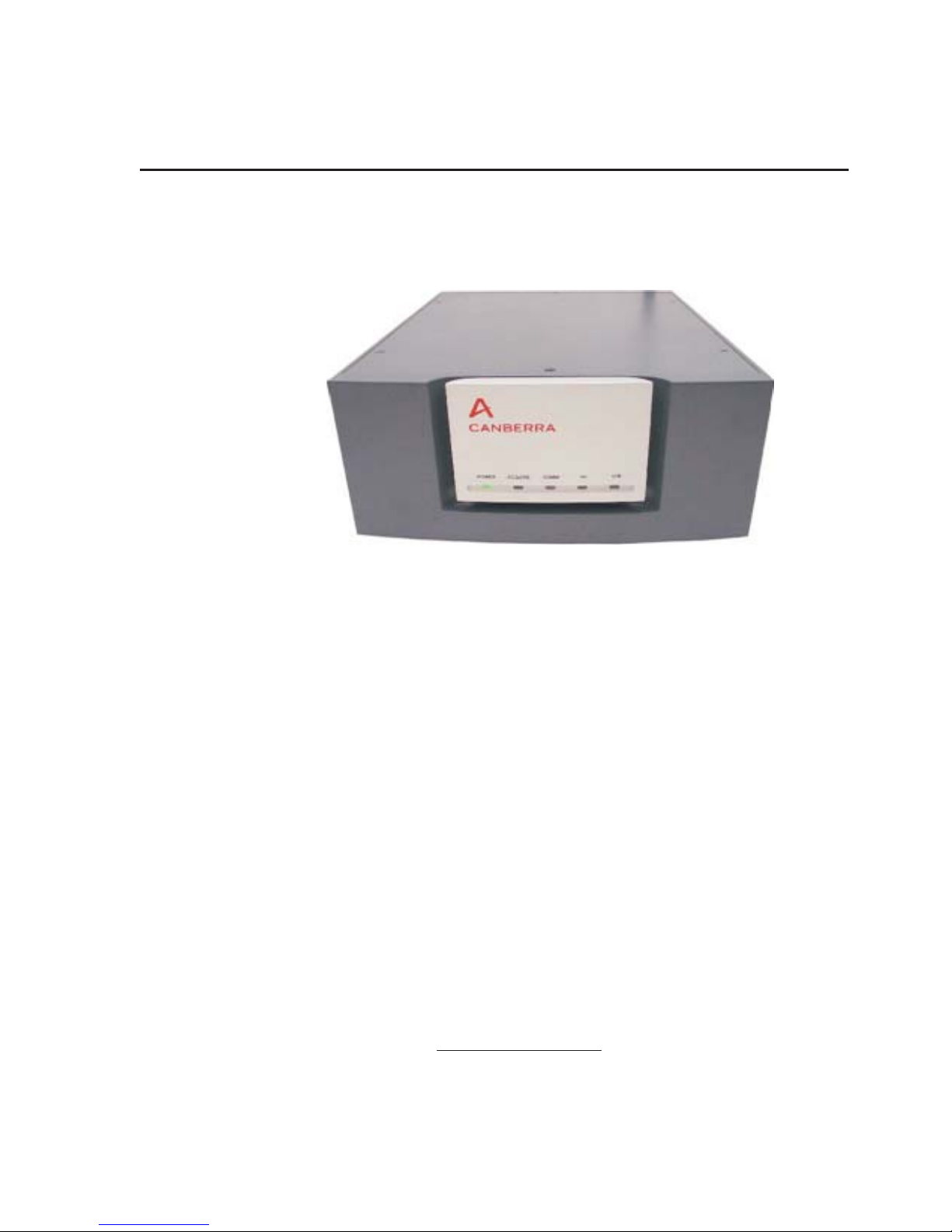
-
Figure 1 - Front View of Lynx DSA
This manual describes the capabilities of the Lynx DSA and its Web-browser-based
control software. Setup and interaction with the Genie 2000 software is reviewed, as it
relates to the Lynx MCA. System setup details for the Lynx system are provided, and
User instructions for data acquisitions is also described.
Comprehensive online help is provided by the Lynx system through its user interface.
Select the Help link on the webpage you are viewing for context-sensitive informa
tion. Quick-Start and Setup steps gloss over details, as a mere 'refresher'.
Quick-Start Information
New, Out-of-the-Box system? Follow the Quick Setup Summary in Appendix B
A User (you) may do the following to quickly access the Lynx (in most cases):
•
Connect and set up the Lynx for a network connection; see Appendix B. Then,
from your computer, launch your Internet browser (e.g., Internet Explorer).
•
Enter the URL for your Lynx DSA : _______________________________
The default URL of http://10.0.0.3/
access the Lynx, STOP, and contact your Lynx administrator.
is factory preset. If you still cannot
-
User’s Manual 1

Chapter 1 - Introduction
Enter your User name and Password (not case sensitive) and click Login.
•
If not yet configured, enter user = administrator and password = password.
The Lynx Menu is to the far left. Under MCA Settings | Acq Setup, change
•
any acquisition parameters as needed from the options offered. Press Submit to
keep any changes made, or Reset to discard your changes here.
The Spectrum controls are to the right of the Menu. Near the top of this frame,
•
select the Spectrum tab, then select Start (under Acquire) to begin.
To Exit, click Logout in the upper left corner, or close your browser window.
•
This Quick-Start is over-simplified. Comprehensive options and settings are discussed
in the following chapters. Lynx user interface settings are covered in Chapter 4.
Note For future reference, fill in the URL for your Lynx system (if using a fixed
IP address) on the line above.
Navigating in this Manual
This manual is a reference to the capabilities and operation of the Lynx DSA. Each of
its chapters covers specific functions.
The Chapters are divided into the following arrangement:
1. Introduction
Starts with a Quick Start as a quick refresher for Users. A sample Energy
Calibration from the browser configuration - a commonly performed task - is
provided as an example of the Lynx interface and commands to introduce a new
user to its operation.
Key Features of the Lynx; an Overview of this guide; an FAQ section. Detailed
setup and User steps are addressed in other areas of the manual, and using the
online help.
2. Controls and Connectors
This chapter includes a brief description of each front panel LED indicator and
each rear panel connector.
3. System Configuration
This chapter includes instructions for setting up a typical system. This chapter
also reviews the interaction with the Genie 2000 Basic Spectroscopy software,
which is required for spectral analysis.
2 Lynx™ Digital Signal Analyzer
4. Web-based Control
This chapter describes how to use a web browser to set data acquisition display
and control parameters, perform system calibration, and acquire data using the
Lynx.
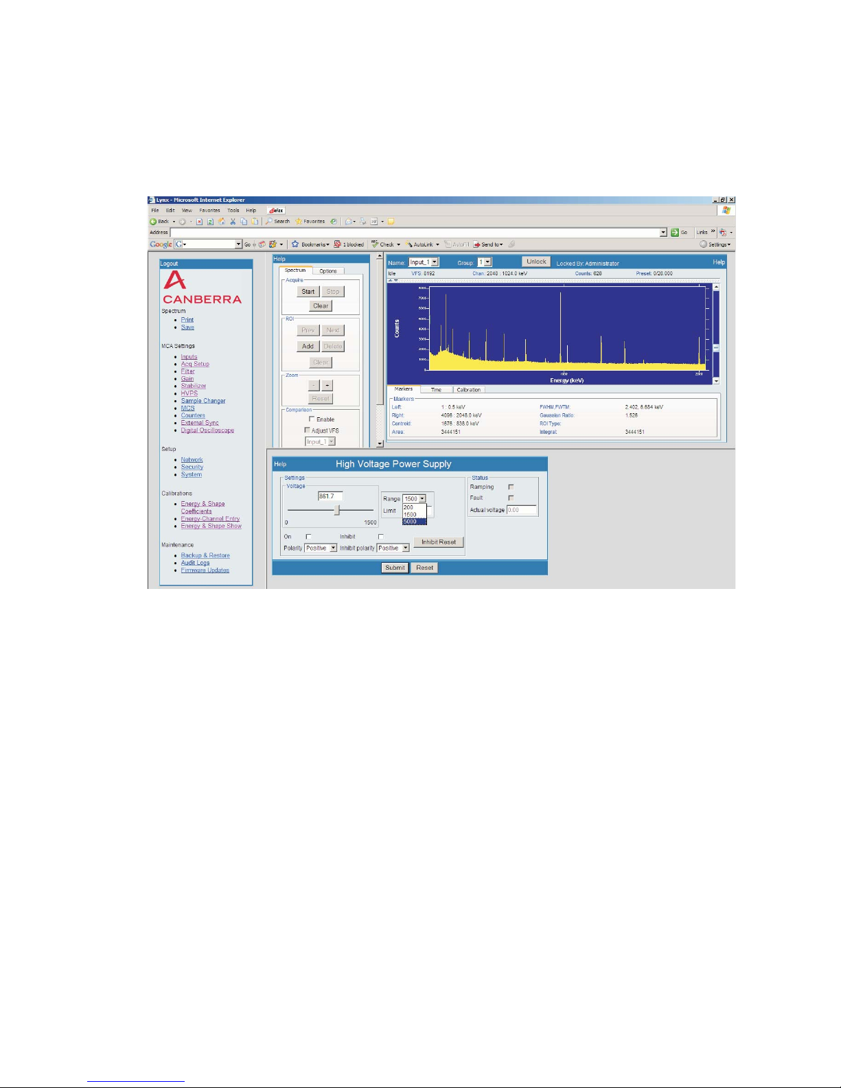
Navigating in this Manual
Figure 2 - Lynx web-based User Interface and display, typical
The Lynx Menu steps are referenced along the top of the manual pages in
Chapter 4 to help guide you through the details.
5. Using the Digital Oscilloscope
This chapter discusses the Lynx’s built-in digital oscilloscope function.
Appendices
The appendices offer useful information not usually needed in day-to-day operation.
Communications Setup in Appendix B offers a summary of network connections
and general user connection instructions for a Network Administrator.
User’s Manual 3

Chapter 1 - Introduction
Key Features
The Lynx includes a full complement of control interfaces for the following: sample
changers, acquisition, external start/stop, coincidence gating, and auto pole/zero.
Support for virtually all detectors used in gamma, x-ray and alpha spectroscopy
•
with up to 32K channels of spectral memory.
Dual user interfaces:
•
Signal shaping filters with appropriate shaping times to support these detectors
•
at a wide range of count rates.
Three separate High Voltage Power Supplies to support detectors with low
•
(PIPS), medium (scintillation) or high (HPGe) voltage requirements.
Full featured acquisition/analysis capability through CANBERRA's
–
Genie™ 2000 and Apex
Live spectral display, acquisition control and calibration via built-in web
–
®
spectroscopy software.
server technology using an Internet browser.
• Multiple counting modes from traditional Pulse Height Analysis (PHA) and
Multichannel Scaling (MCS) analysis modes to LIST and Multispectral Scaling
(MSS) modes. The latter two are of interest when continuous counting intervals
are needed for position or time-based analyses. Auxiliary Counters are also
supported.
• Multiple computer interfaces with routable TCP/IP and DHCP network support:
– 10/100 Base-TX Ethernet for fast network connections over any distance.
– USB and Ethernet for fast, convenient local connections.
–
RS-232 for instrument control and specialized or legacy connections.
–
Modem support for remote monitoring and setup.
•
Advanced Auto Pole/Zero, Base Line Restoration and Digital Stabilization.
•
Adjustable digital signal delay for Coincidence timing applications (0–100 µs in
0.1 µs steps).
•
Multiple trace oscilloscope (digital and analog) for performance optimization
with various applications.
•
Full complement of input/output interfaces (BNC connection) for external
control including: TRP Inhibit, HV Inhibit, MCS In, PHA and MCS Start/Stop,
MCS Channel and Sweep Advance, Coincidence/Anticoincidence Gating,
Sample Changer control, plus general-purpose I/O connectors.
•
Flexible form factor: for Standalone Desktop use; or rack-mount – one Lynx
unit, or two Lynx units side by side, may be rack-mounted in 2U of a standard
19 inch electronics cabinet using the optional rack-mount kit.
4 Lynx™ Digital Signal Analyzer

Acquisition Modes
The Lynx™ supports several acquisition modes:
PHA Mode
The PHA (Pulse Height Analysis) mode acquires energy-correlated data. Each chan
nel, defined as an energy window, is incremented by one count for each event that
falls within the window, producing a spectrum which correlates the number of energy
events as a function of their amplitude.
DLFC Mode
The DLFC (Dual Loss Free Counting) mode of operation allows real-time acquisition
of events, and will produce two spectra. One spectrum contains live time corrected
counts, and the other produces the normal uncorrected counts. Each spectrum may be
viewed from the web display via the memory groups. Memory group 1 displays the
corrected spectrum. Memory group 2 displays the uncorrected spectrum.
MCS Preset Mode
The MCS (Multichannel Scaling) mode acquires time-correlated data. Each channel is
sequentially allocated a dwell time (a specified time period) for accumulating counts
until all the memory has been addressed.
Key Features
-
MSS Mode
The MSS (Multispectral Scaling) mode, also called “ping-pong” mode, alternately
collects PHA data in two separate memory groups, quickly collecting many spectra
with extremely low latency between acquisitions.
List Modes
In Standard List mode, each energy event is stored sequentially in memory, one
word per event.
In Time-Stamped List Mode, the time of arrival of each energy event is tagged
with the time of arrival. The list data can then be read using standard spectral data read
utilities and energy and time-correlated spectra can then be created from the data.
Auxiliary Counters
Auxiliary Counters are supported. If using the Lynx Programming Libraries, heed the
Caution statements before Enabling Counters. See MCA Settings | Counters.
Digital Storage Oscilloscope (DSO)
Lynx incorporates a multi-trace digital and analog oscilloscope. This mixed-signal os
cilloscope is included for system performance optimization and flexibility.
-
Single Channel Analyzer (SCA)
The Lynx supports up to eight programmable SCA's.
User’s Manual 5

Chapter 1 - Introduction
FAQ & Common Events
The browser-based Menu controls are discussed in detail in Chapter 4. An overview of
common tasks and events is offered here. A simplified menu and sub-menu item refer
ence is provided to guide you along.
To begin, access the Lynx, and MAXIMIZE your Internet browser window.
-
Remember
Access the Lynx system
You connect to the Lynx through another computer or terminal, and your site's access
parameters will be unique. See the Quick Start, or review the Setup starting in Chap
ter 3 and the browser-based network User Interface starting in Chapter 4. Appendix B
includes a Quick Setup summary of communication connections, helpful to Network
Administrators.
Create a new User Name and Password
See Setup | Security. Security features, including the need for to enter a Name and
Password, are enabled by default to ensure system settings are not inadvertently or accidently changed.
Note Changes here may affect other users or the entire system, so be careful.
Do NOT: Press Clear;
After making changes, press Submit to save your new data.
Review the Help file or additional information found the description of the
Security feature, described in Chapter 4. Details begin on page 114.
or Uncheck Web site login button;
or change the Administrator Account password.
-
If you did:
Please DO: Enter the login name in the User field, and password in that
•
Web site Login MUST be checked. Leave Admin Account field as is.
•
Select the checkboxes for desired Menu features.
•
Click Add. Click Submit to keep it.
Log out, and log in with this new User account to verify its operation.
6 Lynx™ Digital Signal Analyzer
Do NOT press Submit, but DO close your browser window.
field. Use alpha-numerics, these are NOT case sensitive;
space and underscore are also allowed.

FAQ & Common Events
Set up the Spectrum's plot options
See Spectrum | Display; or, in some browsers, the display controls are already open.
Select an Input by Name: (centered, above the spectral display). Click the Options
tab in the display controls. Set the plot options as desired; your changes are immediate.
Rename an Input
See MCA Settings | Inputs. Alphanumeric, 4 to 14 characters suggested.
Setting to Unlock a Locked Input
See Spectrum | Display. Depends on your Take Over setting.
To Enable the ability to Unlock an Input:
Setup | Security | <your User name>; Take Over button must be checked.
Save the CAM file of your acquisition (for use with Genie 2000, etc.)
See Spectrum | Save. Click the Save menu button.
•
• Right-Click on the here
link on the Save Input pop-up page.
• Select Save Target As... from the pull-down list (do NOT open the file).
• The Save As page will open. Select the storage drive location you wish.
• Edit the File name, changing it to something appropriate to describe your
Input, using the format <filename.cnf>. (This will be your CAM file when
done).
• Click Save to write the new CAM file to the desired location.
Change Input Definition
First, select the Input Name from the list at the top-center of the spectrum display.
Then, go to MCA Settings | Inputs. Choose the Acquisition Mode from the list.
Set Input type and typical Definition information
See MCA Settings | Acq Setup. Only parameters for your type of Input are offered.
Set Presets
See MCA Settings | Acq Setup. Only supported presets will be offered.
Set External Start/Stop options
See MCA Settings | Acq Setup. Supported options are presented.
Digital Oscilloscope
Best if used with Internet Explorer or Opera, or a Java compliant browser. Chapter 5
of this User's Guide is dedicated to this feature.
User’s Manual 7

Chapter 1 - Introduction
Sample Energy Calibration
Energy Calibration using the browser-based interface is provided as an example be
low. This will help demonstrate how you will use the Lynx.
This is an overview only; specific Lynx setup options and details are described in this
manual, especially in Chapter 4 which discusses the Menu and options in detail.
User Controls for Calibrations are described starting on Page 128, and demonstrated in
this section.
Lynx Energy Calibration Setup Steps
These steps assume the Lynx is already set up, including your detector and sample.
Gather Data from your Acquisition
1.)
Ensure the HVPS for your detector has been activated, e.g., in the On state
(review this HVPS setting on page 92). Be certain that the Gain Attenuator
is set to the Off position (discussed in Step 3, below; review this Gain
setting on page 87 of this manual). Verify the settings for your Detector's
preamp type.
-
2.)
Start your collection. Press the Start button in the Acquire area of the
Spectrum tab to begin the acquisition.
Figure 3 - Spectrum Controls, with Start pressed
If Start is pressed, and Clear is then pressed, the acquisition will simply
'restart'. If Stop is pressed, the acquisition will stop collecting.
8 Lynx™ Digital Signal Analyzer
Sample Energy Calibration
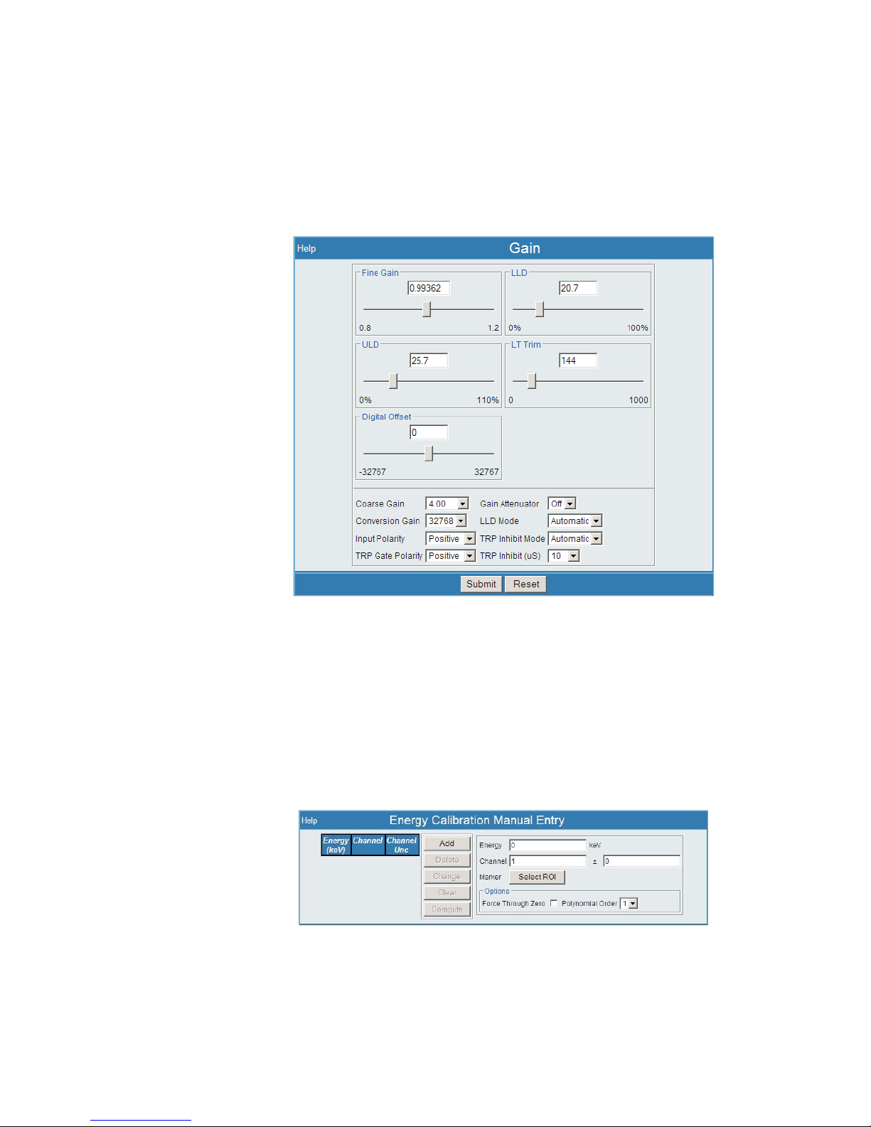
3.)
From the Lynx Menu, select Gain under MCA Settings.
While observing the spectrum display, use the Coarse Gain and Fine Gain
to adjust your desired peaks into the area or correct channels. This is also
creating the required slope data for your energy calibration.
Figure 4 - Using Gain Setup (under MCA Settings)
4.)
Once the desired peaks are in or around (as for NaI type detector) the desired
channels, count your spectrum. Consider the strength of your source and the
count time needed to ensure an adequate count rate acquisition.
5.)
Select the Calibrate | Energy-Channel Entry menu option.
Figure 5 - Energy Channel Entry menu page
User’s Manual 9
Chapter 1 - Introduction
Use your Acquired data to Calibrate
6.) Reviewing your spectrum, choose the lowest energy peak needed for the
Note Each of the above are performed in this order, in the following steps.
6a.)
Using the cursor and then selecting the CTRL-L key which will position the Left cursor, and then CTRL-R key for the Right cursor; then, either press the Add ROI button or press the Insert key to paint the desired ROI.
energy calibration and perform the following functions.
Create an Region of Interest (ROI) around the peak
–
Press the Select ROI button
–
Type in the correct Energy value
–
Select the Add button to add the desired energy and ROI data to the
–
Energy-Channel list
Create a list of peaks to be used for the Energy Calibration
–
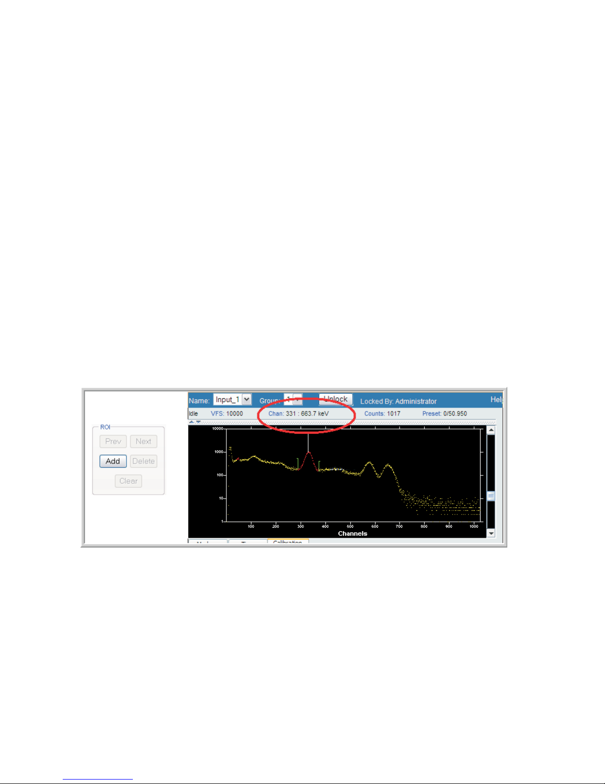
First, create an Region of Interest (ROI) around the peak.
The Energy value for that peak is displayed across the top of the spectral display. See
Figure 6 and look for the Chan: field, which in this example shows 663.7 keV.
10 Lynx™ Digital Signal Analyzer
Figure 6 - Adding an ROI
Sample Energy Calibration
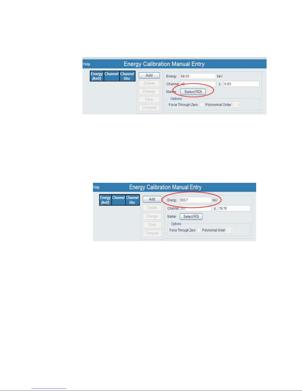
6b.)
Now you want to set your marker, selecting the Region of Interest. Press
the Select ROI button.
Figure 7 - Selecting the ROI
6c.) Next, using the data from the acquisition, enter in the correct Energy value.
Again, this was 663.7 keV from this example, as seen back in Figure 6.
Enter this value into the Energy field on the Energy Calibration Manual Entry
page.
Figure 8 - Enter the Energy Value
User’s Manual 11
Chapter 1 - Introduction
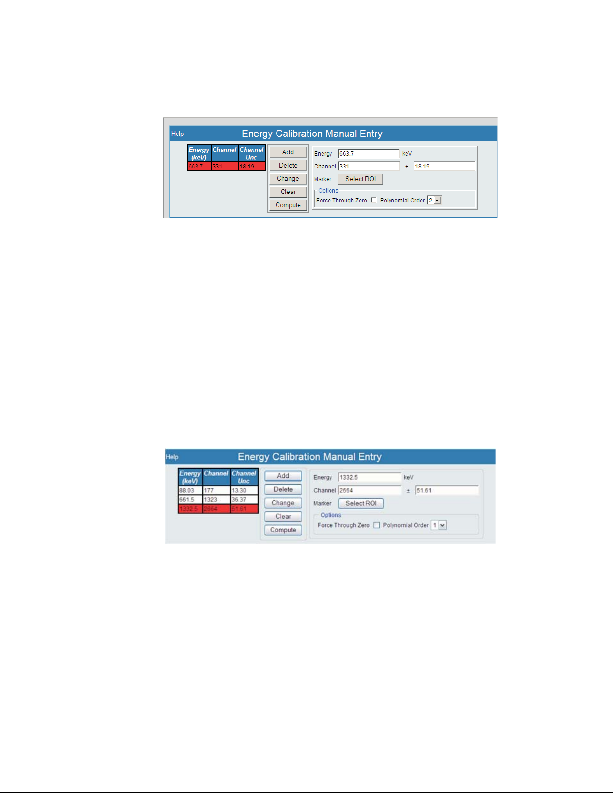
6d.)
Your new value will then appear under the Energy list to the left of this pane. It will
appear in 'red' indicating that this is a new parameter, and still needs to be submitted.
Now, select the Add button to add the desired energy and ROI data to the list
of Peaks.
Figure 9 - Your Energy Value has been Added
Repeat this process for each energy peak to ensure linearity in your Energy calibration
(low + high energy 2 pt calibration).
Repeat Steps 6a) through 6d) until you have entered your data points.
6e.)
The List of peak energies to be used in the Energy - Channel Entry list is
now complete.
Figure 10 - List of Energies
12 Lynx™ Digital Signal Analyzer
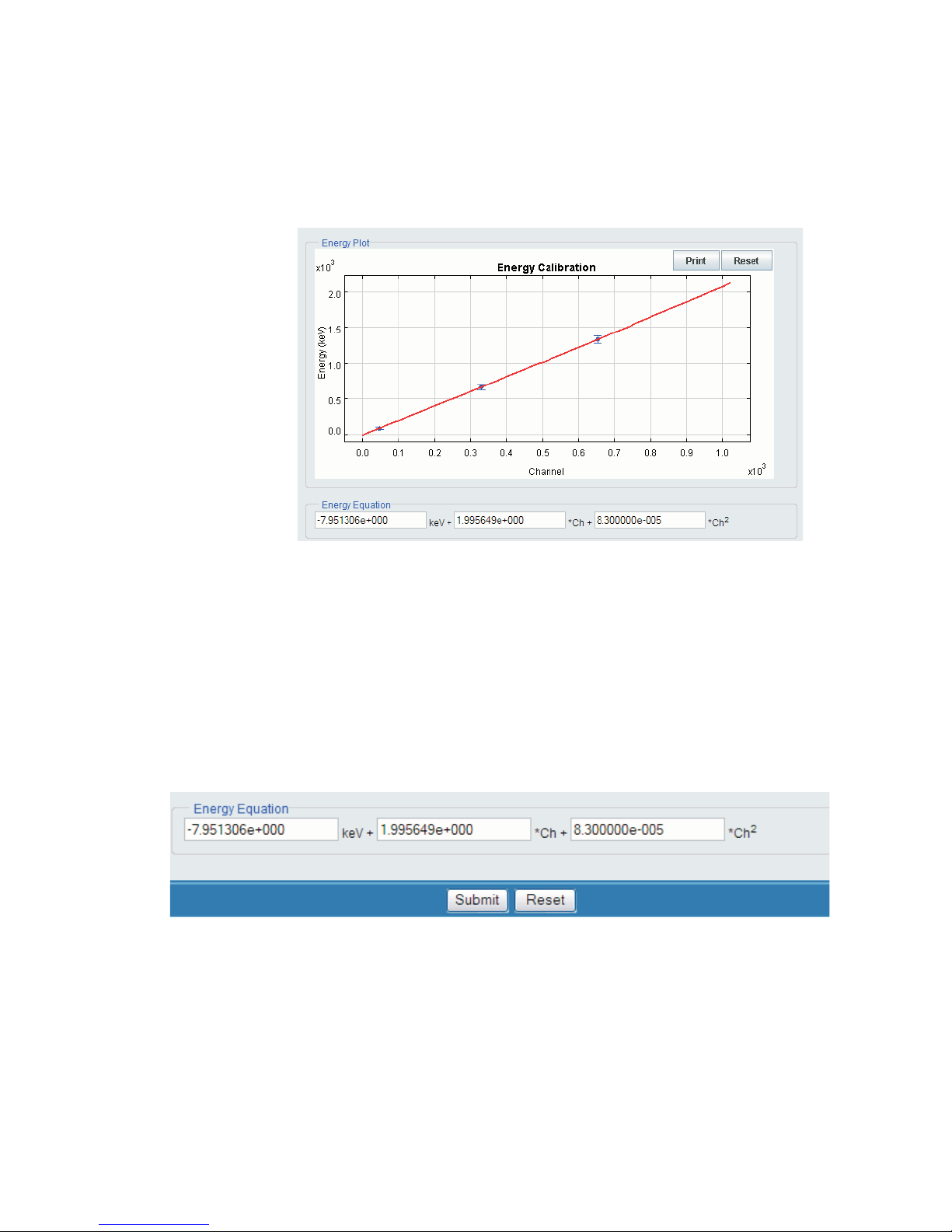
Compute using your Data
7.)
Select the Compute button to calculate the Energy calibration and
coefficients.
Sample Energy Calibration
Figure 11 - Energy Equation
The Energy Equation plot appears as a result of your data input.
Saving the Energy Equation and Coefficients
8.)
Press the Submit button to save the configuration for the Input selected.
Figure 12 - Submit to Save the Energy Equation and Coefficients
User’s Manual 13
Chapter 1 - Introduction
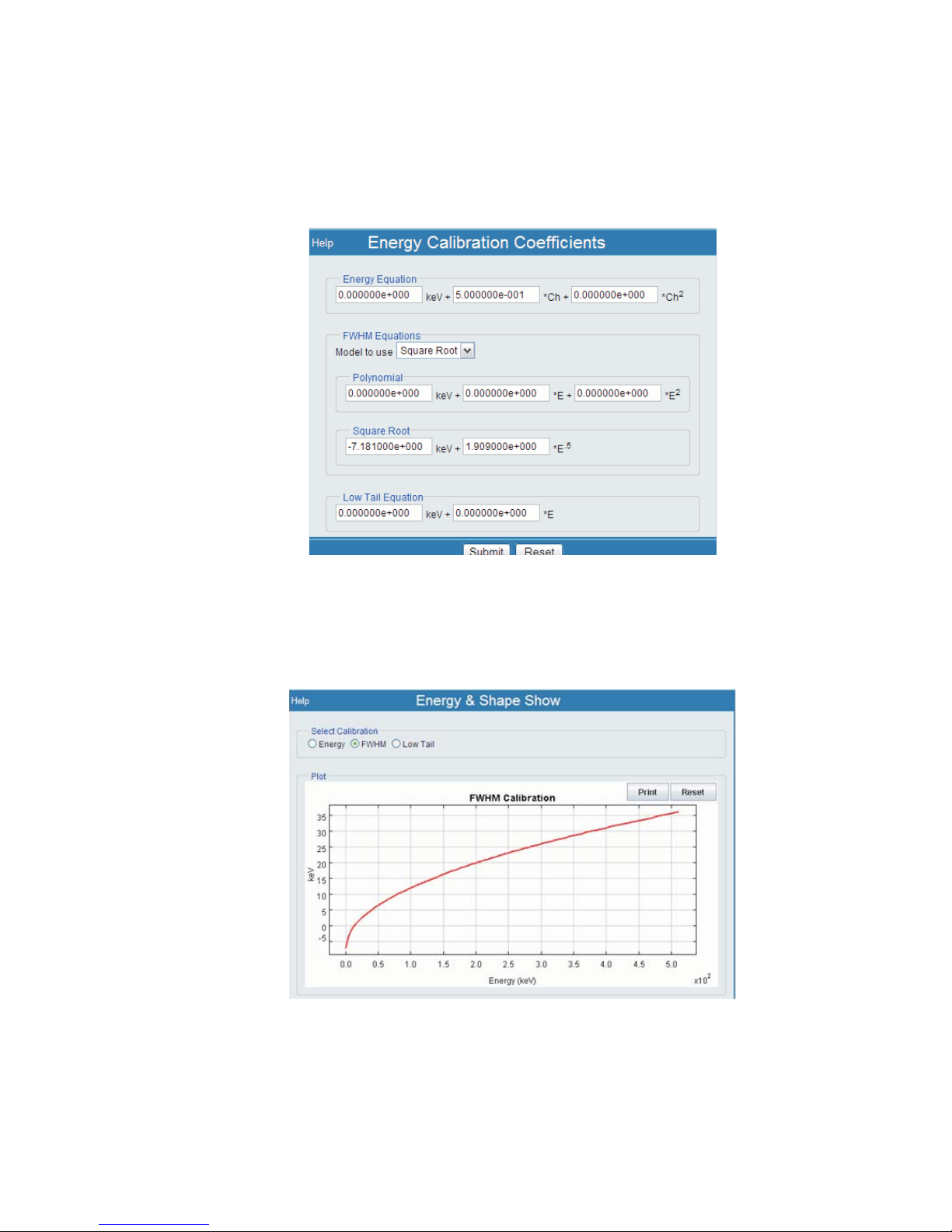
FWHM Parameters
9.)
FWHM parameters must be entered manually, on the Energy Calibration
Coefficients page.
Figure 13 - Energy Calibration Coefficients
The FWHM Shape (for this example) can be seen as shown in Figure 14.
Figure 14 - FWHM Shape
The calibration is complete at this point.
14 Lynx™ Digital Signal Analyzer

2. Controls and Connectors
Lynx has several functional indicators on its front panel and a number of connectors
on the rear panel. This chapter includes a brief description of each one.
Most operations and controls of the Lynx are remotely operated through the Lynx user
interface, using a PC or PDA equipped with an Internet Browser.
There are no user controls on the unit itself, and the indicators show status and some
indications that may be used to verify a setup, however there are no 'user' indicators
that require the Lynx be visible to the user.
Front Panel Indicators
The Front Panel LED indicators (Figure 15) are summarized on page 16.
Front Panel Indicators
It is not absolutely necessary to be able to observe these indicators during operation, as
the real-time results are displayed in the Lynx's user interface. However, before inter
acting with the connectors on the rear of the Lynx unit, you may wish to observe these
status indicators for your own safety.
For more information, refer to Appendix A, Specifications.
User’s Manual 15
Figure 15 - Front Panel showing LED Indicators
-

Chapter 2 - Controls and Connectors
LED Status
POWER
A multicolor LED showing instrument status and presence of system power. The dif
ferent LED states may be observed during or after the power-up self test.
Blinking Green – Instrument is powered on and in the process of initialization.
•
Steady Green – Instrument is powered on and ready for operation.
•
Steady Red – Signals a self-diagnostic error. The reason for the error can be
•
confirmed through the appropriate control software (Genie 2000 or the web
interface). A Diagnostic procedure is available if the Lynx interface is
operational.
LED is Off – Instrument is not receiving power.
•
ACQUIRE
A green LED. Steady on when a setup on the instrument is acquiring data.
-
COMM
A green LED for Communications. Illuminates each time the instrument has received
a command over any supported communications interface.
HV
A multicolor LED indicating the state of the selected high voltage power supply, or in
some cases, relating to any of the high voltage power supply outputs.
• Off – High voltage supply is off. ALL HVPS Outputs are off.
•
Blinking Green – ANY High voltage supply is ON and ramping up to its
programmed voltage.
•
Steady On Green – ANY High voltage supply is ON and has reached its
programmed voltage.
•
Steady On Red - An error, such as a HVPS fault has occurred (e.g., Inhibit has
tripped, etc.). This 'error' condition may be cleared by the User with knowledge
of what caused the fault to occur (i.e., a known limiter was tripped).
ICR
A green LED for Incoming Count Rate. Illuminates each time the instrument processes
an incoming signal. The intensity of the LED is proportional to the incoming count
rate.
16 Lynx™ Digital Signal Analyzer
 Loading...