

Page 1
MultiMux
Multiplexer
USER’S GUIDE
Disclaimer: The following document is provided to assist users with the installation, operation
and training in the use of our products. This document and our products are intended to be used
by technically qualified personnel. Contained herein is information that is proprietary to Canary
Systems and may not be reproduced or copied in any form, nor disclosed to outside parties by
any means whether directly or indirectly, without the written consent of Canary Systems. This
document is subject to change without notice and Canary Systems assumes no responsibility for
errors, omissions or misinterpretation. Furthermore Canary Systems makes no warranty as to the
suitability of this information and/or products for any given application or use.
Copyright1998-2007 Canary Systems, Inc. All Rights Reserved.
Multimux_usersguide.doc Revision D, 07-07
75 Newport Road, Suite 211
New London, NH 03257 USA
e-mail: [email protected]
web: www.canarysystems.com
Canary Systems, Inc.
Voice: (603) 526-9800
Fax: (603) 526-9004
Page 2

Table of Contents
Section 1 Introduction
1.1 Overview........................................................................................ 3
1.2 Specifications................................................................................. 4
Section 2 MultiMux Operation and Installation
2.1 Operation Details........................................................................... 5
2.2 Datalogger Connection .................................................................. 6
2.3 Instrument Connection................................................................... 7
2.4 MultiLogger Software Configuration............................................... 7
2.5 CR10/CR10X Program Example.................................................... 8
2.6 CR1000 Program Example............................................................ 9
2.7 CR1000 Program Example with VWDSP....................................... 9
2.8 Enclosure Installation..................................................................... 11
2.9 Lightning Protection....................................................................... 11
2.10 DaisyMux Operation..................................................................... 12
Section 3 Troubleshooting
3.1 Troubleshooting Flowchart............................................................. 14
Page 3
Section 1 - Introduction 3
223.8mm
273.05mm
1.1 Overview
The MultiMux expands the number of instruments that may be read by the CR10 or CR10X in increments
of 16, 32 or 48, depending on the model purchased and the type of sensor being read. In addition the
MultiMux provides integral lightning protection by utilizing plasma surge arrestors (optional). The MultiMux
may be purchased installed in a NEMA 4X fiberglass/polyester enclosure or as a board assembly for
users supplying their own packaging.
The complete list of features and ordering options is detailed on the MultiMux Ordering Guide available
from our web site or by contacting Canary Systems directly.
The MultiMux consists of two printed circuit boards (PCB’s), one for making the instrument connections
(the terminal board) and the second, installed on the back of the terminal board (the switch board), for
switching the instrument leads. The MultiMux utilizes advanced high-reliability components such as
terminal blocks from Phoenix Contact (http://www.phoenixcontact.com), relays from Aromat
corporation (http://www.aromat.com) and a microcontroller from Microchip Devices
(http://www.microchip.com) to help insure years of reliable and trouble-free operation. The use of low
contact resistance relays means almost universal instrument support, a high degree of lightning
protection and virtually infinite channel isolation.
Warranty is applicable for 2 years from date of shipment. Warranty does not cover failure by misuse or by
nature including lightning, flood, or other catastrophe. Should you encounter problems with your MultiMux
see the troubleshooting flowchart in section 3.
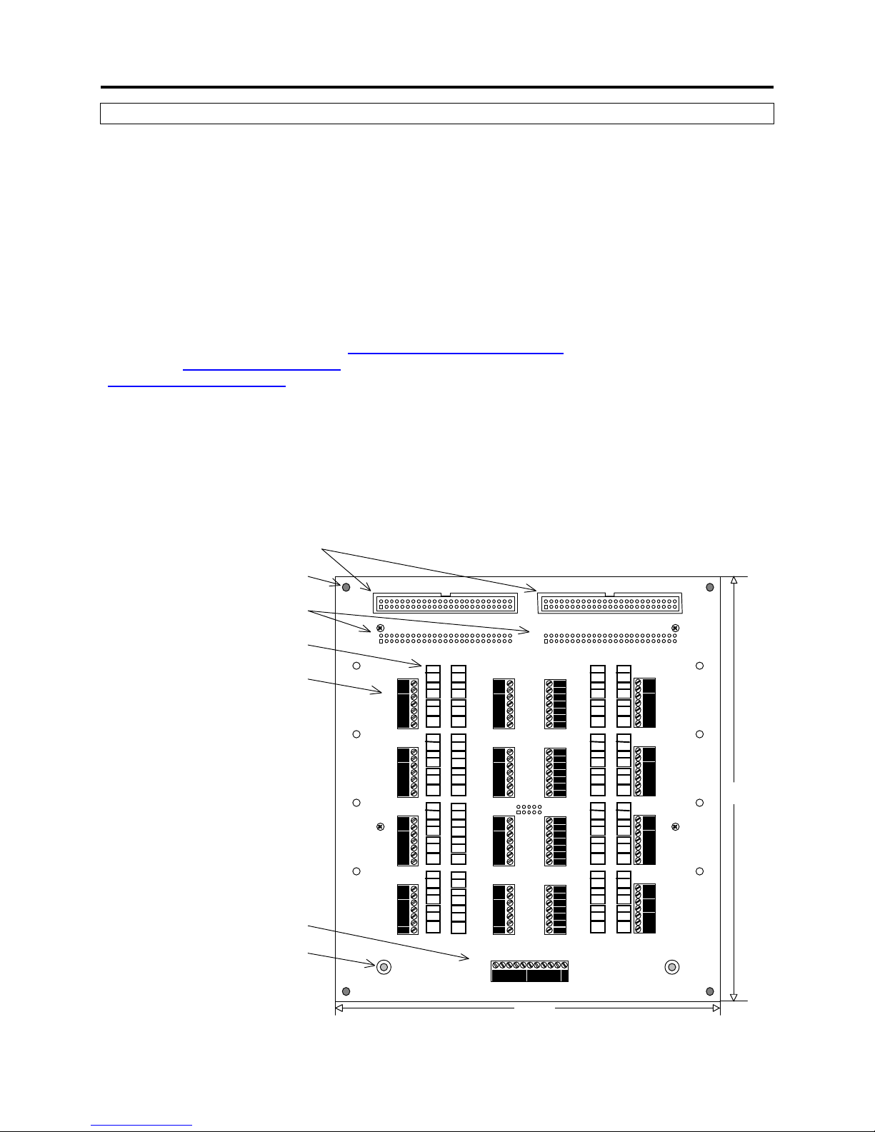
A top view and description of the MultiMux terminal board is shown below.
Manual Switch Header Sockets (optional)
Mounting Hole (4 places)
Interboard Connectors
Surge Arre stors (optional)
Screw Terminal Blocks (16 places)
Datalogger Connection
Earth Ground Connection (2 place s)
Canary Systems, Inc.
J3
J1
SA1
TB1
1H1
SA2
TB2
TB3
TB4
SA3
SG1
SA4
SA5
SA6
SG2
SA7
SA8
SA9
SG3
SA10
SA11
SA12
SG4
SHIELD
SHIELD
SHIELD
SHIELD
1L1
1H2
1L2
1H3
1L3
2H1
2L1
2H2
2L2
2H3
2L3
3H1
3L1
3H2
3L2
3H3
3L3
4H1
4L2
4H2
4L1
4H3
4L3
SA13
SA14
SA15
SA16
SA17
SA18
SA19
SA20
SA21
SA22
SA23
SA24
TB5
5H1
5L1
5H2
5L2
5H3
5L3
SG5
SHIELD
TB6
6H1
6L1
6H2
6L2
6H3
6L3
SG6
SHIELD
TB7
7H1
7L1
7H2
7L2
7H3
7L3
SG7
SHIELD
TB8
8H1
8L2
8H2
8L1
8H3
8L3
SG8
SHIELD
Datalogger Connection
TB17
1H 1L
2H 2L 3H 3L
16/32/48 CHANNEL TERMINAL BOARD
J4
J2
SA25
TB9
TB10
J5
TB11
TB12
9H1
SA26
9L1
9H2
SA27
9L2
9H3
9L3
SG9
SHIELD
SA28
10H1
SA29
10L1
10H2
SA30
11L2
11H3
11L3
SG10
SHIELD
SA31
12H1
SA32
12L1
12H2
SA33
12L2
12H3
12L3
SG11
SHIELD
SA34
13H1
SA35
13L1
13H2
SA36
13L2
13H3
13L3
SG12
SHIELD
EN 12V G
CLK
S
SA37
SA38
SA39
SG13
SA40
SA41
SA42
SG14
SA43
SA44
SA45
SG15
SA46
SA47
SA48
SG16
TB13
TB14
TB15
TB16
13H1
13L1
13H2
13L2
13H3
13L3
SHIELD
14H1
14L1
14H2
14L2
14H3
14L3
SHIELD
15H1
15L1
15H2
15L2
15H3
15L3
SHIELD
16H1
16L1
16H2
16L2
16H3
16L3
SHIELD
10.750"
8.813"
Page 4
Section 1 - Introduction 4
1.2 Specifications
General
Power requirements: 9-16 VDC (unregulated)
Quiescent current: 100 µA
Channel activated current (2 or 4-wire): 40 mA
Channel activated current (6-wire): 50 mA
Control line input impedance: 10 kilohms
Control line input levels: TTL or CMOS (5V logic)
Transient protection: 18 VDC, 1500W Transzorbs
Operating temperature: -40 to +70° C (-40 to +160° F)
Relays
Power: 11 mA @ 12VDC (140 mW)
Contact type: Gold-clad silver alloy
Electrostatic capacitance: 3 picofarads
On resistance: 50 milliohms
Coil resistance: 1,028 ohms
Maximum switching voltage: 125 VAC, 110 VDC
Maximum switching power: 30 W (resistive load)
Maximum switching current: 1 A
Operate time: ~2 milliseconds
Release time: ~1 milliseconds
Initial contact bounce: ~1 millisecond
Surge withstand (between open contacts): 1,500 V
Switching life (mechanical): 100,000,000 operations
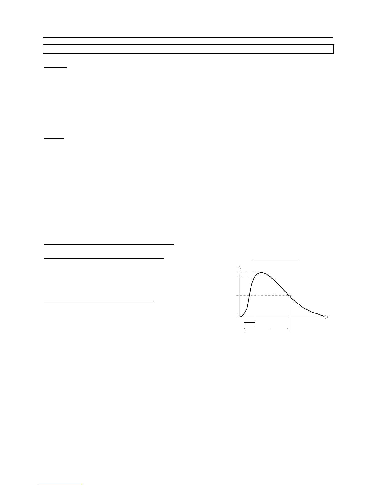
Lightning Protection Components (optional)
Tripolar Plasma Surge Arrestor (SA1-SA48)
Nominal DC breakdown voltage: 250 V
Surge life: 400 (10/1000 ms pulse @ 500 Amps)
Maximum surge current: 10 kA per side (8/20 µs pulse)
Insulation resistance: 10,000 Megohms
Bipolar Plasma Surge Arrestor (SG1-16)
Nominal DC breakdown voltage: 230 V
Surge life: 1,000 (10/1000 µs pulse @ 500 Amps)
Maximum surge current: 20 kA (8/20 µs pulse)
Insulation resistance: 10,000 Megohms
Current
100%
90%
50%
10%
0%
Surge Waveform
10ms
1000ms
Time
Page 5
Section 2 – MultiMux Operation and Installation 5
2.1 Operation Details
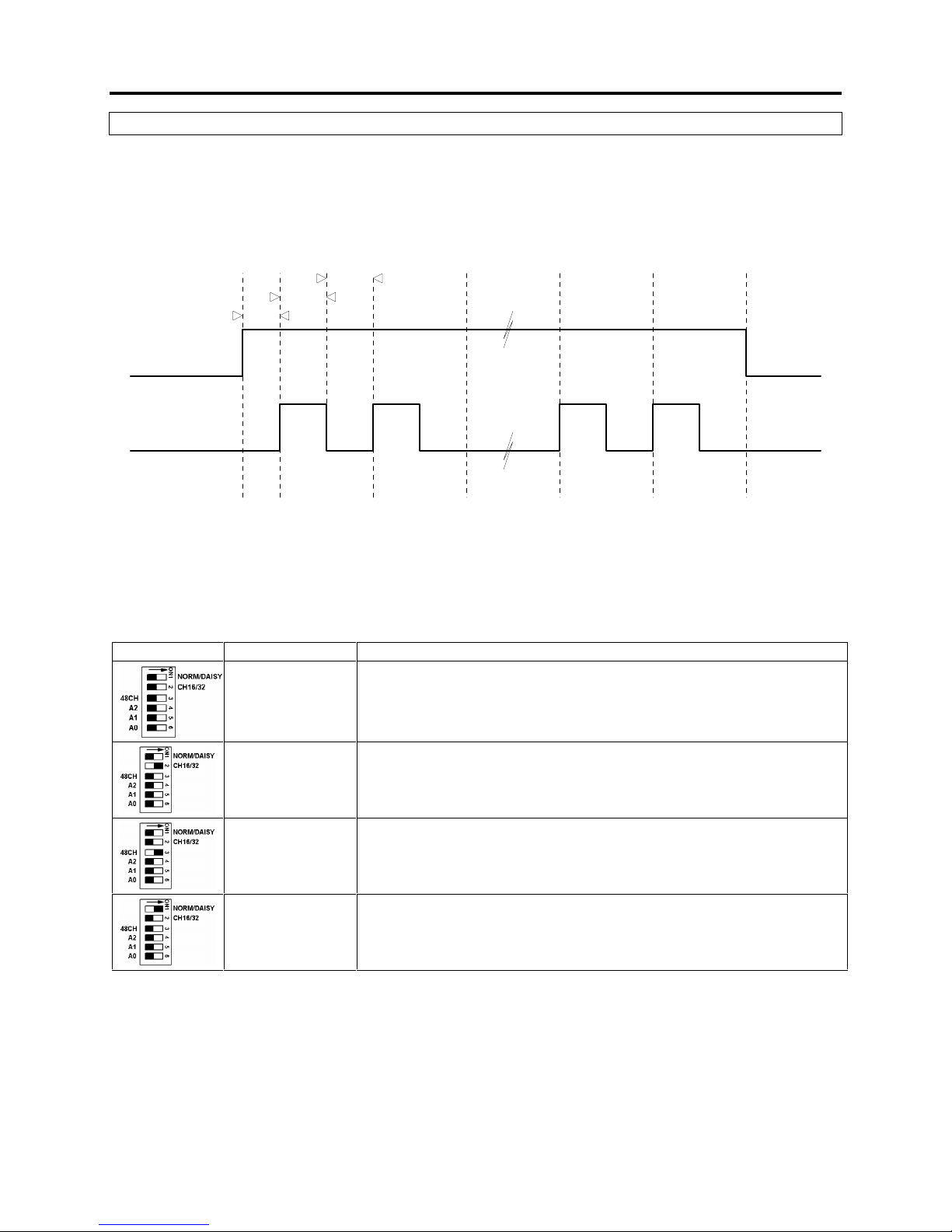
The MultiMux is controlled by the CR10 or CR10X Controller using 2 digital control signals. The operation
of the MultiMux is simple enough so that virtually any device capable of controlling 2 digital TTL/CMOS
type signals can be used to control the multiplexer. Generally speaking the timing diagram depicted below
describes how the 2 digital signals are used to control the MultiMux.
Enable
Note: Timing values shown are minimum values.
250ns
250ns
50ms
Clock
Selected
1 2 15 16
Channel 1No Channel
Channel 2
Selected
Channel 15
SelectedSelected
Channel 16
Selected
No Channel
Selected
In the case of the 32 or 48 channel modes the maximum number of pulses to advance through all the
channels would be 32 and 48, respectively.
The channel switching mode is selected by configuring the DIP switch mounted on the MultiMux relay
board (mounted under the terminal board). The table shown below describes the 4 possible
configurations.
DIP Settings Mode Description
16 Channel Standard mode for switching 4 or 6-wire instruments (default).
32 Channel Switching 32 2-wire instruments.
48 Channel Switching 48 2-wire instruments (optional).
DaisyMux Mode where control signals are common to more than 1 multiplexer.
The factory default setting is 16 Channel mode (unless specified otherwise).
See section 2.8 for more information on DaisyMux mode.
Page 6
Section 2 – MultiMux Operation and Installation 6
2.2 Datalogger Connection
The MultiMux is connected to the CR10/CR10X Controller or MultiLogger Mux Terminal Board (or ML
MUX TB) using the screw terminals on the terminal board.
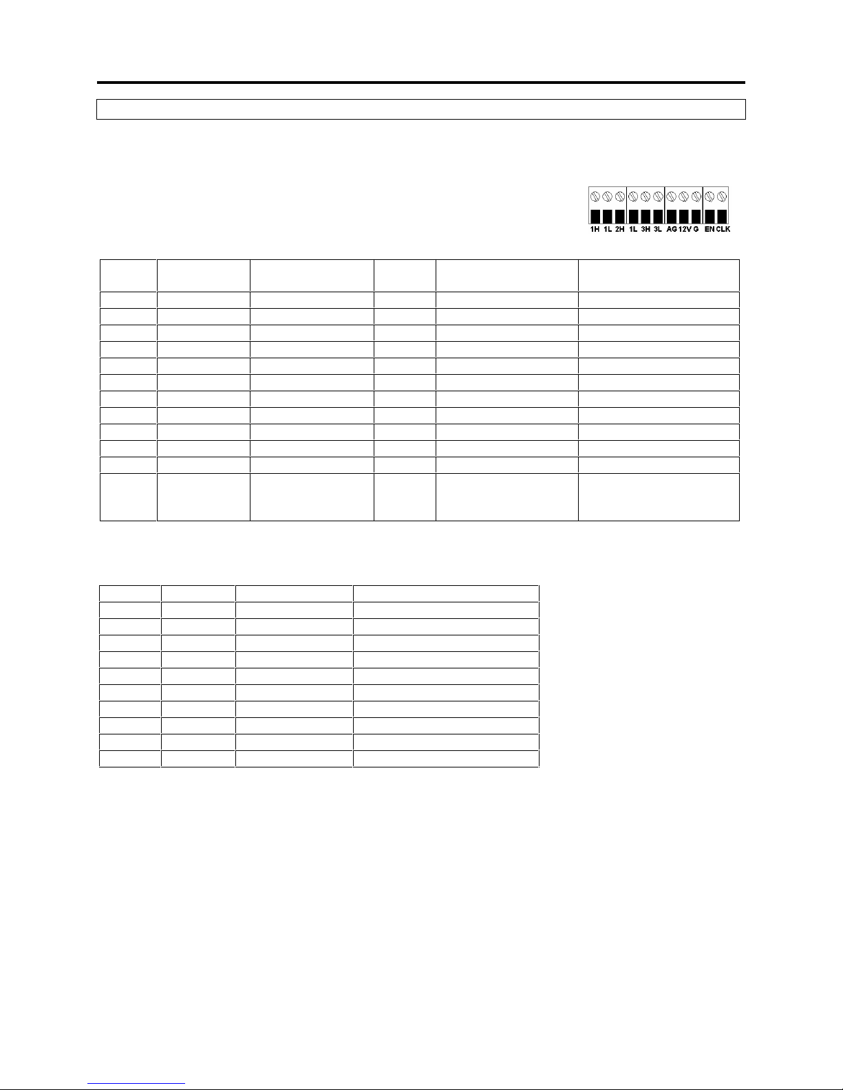
The screw terminal block located on the bottom of the terminal board has the
following connections:
The table below lists the connections for the screw terminal block.
TB ML MUX TB
Connection
1H 1H
1L 1L
2H 2H
2L 2L
3H NC
3L NC
AG S
12V 12V
G GND
EN EN
CLK CLK
S
If using the MultiSensor Interface with your CR10 or CR10X then connect from the 10-pin connector
(using the supplied cable) on the Interface to the screw terminals of the MultiMux in the following order:
Pin Color Connection Description
1
2
3
4
5
6
7
8
9
10
The MultiSensor Interface does not support the 6-wire switching capability of the MultiMux so the 3H and
3L terminals are not connected.
Brown 1H
Red 1L
Orange 2H
Yellow 2L
Green AG
Blue 12V
Purple G
Grey EN
White CLK
Black Cable Shields
Description Bendix Mux Cable
(5 pair)
High side of CH1 A White Brown
Low side of CH1 B White’s Black Brown’s Black
High side of CH2 C Red Red
Low side of CH2 D Red’s Black Red’s Black
High side of CH3 White
Low side of CH3 White’s Black
Gage shield E Blue & Blue’s Black Blue & Blue’s Black
Power F Yellow Yellow
Ground G Yellow’s Black Yellow’s Black
Enable H Green Green
Clock J Green’s Black Green’s Black
Cable Shield K Shield Wires from
White & Red Pair
plus Overall
Low side of CH1
High side of CH1
Low side of CH2
High side of CH2
Gage shield
Power
Ground
Enable
Clock
Cable Shield
Mux Cable
(6 pair)
Shield Wires from
Brown & Red Pair plus
Overall
Page 7
Section 2 – MultiMux Operation and Installation 7
2.3 Instrument Connection
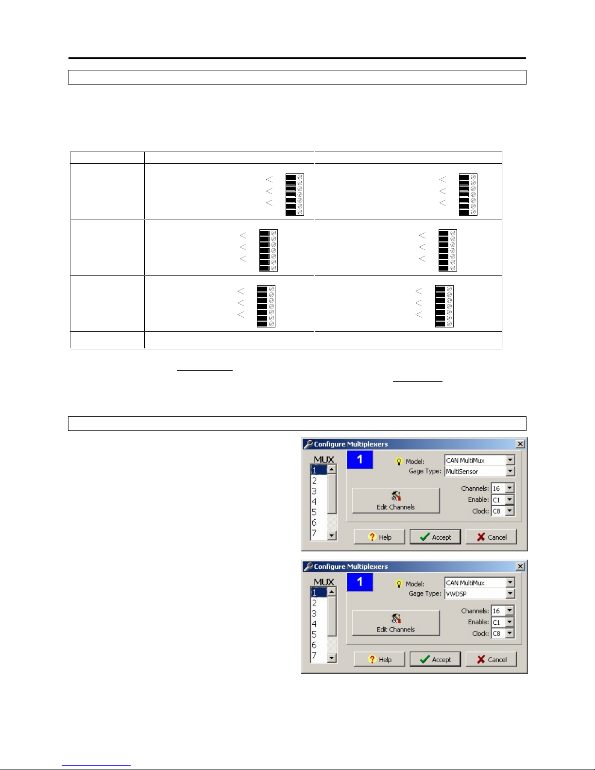
The way instruments are connected to the MultiMux will vary slightly depending on the Mode selection
(section 2.1).
The following table illustrates typical connection techniques for each of the operating modes.
Mode Description Example
16 Channel
(4-wire)
32 Channel
48 Channel
Instrument #1
Temperature for Instrument #1
No Connection
SHIELD
SHIELD
1H1
1L1
1H2
1L2
1H3
1L3
1H1
1L1
1H2
1L2
1H3
1L3
Instrument #1
Instrument #2
No Connection
Instrument #1
Instrument #2
Instrument #3
TB1
TB1
SHIELD
TB1
1H1
1L1
1H2
1L2
1H3
1L3
Thermistor in VW Gage #1
VW Gage #1
No Connection
SHIELD
SHIELD
1H1
1L1
1H2
1L2
1H3
1L3
1H1
1L1
1H2
1L2
1H3
1L3
VW Gage #1
VW Gage #2
No Connection
VW Gage #1
VW Gage #2
VW Gage #3
TB1
SHIELD
TB1
TB1
1H1
1L1
1H2
1L2
1H3
1L3
DaisyMux Same as 16 Channel Mode Same as 16 Channel Mode
If the CR10 or CR10X is not equipped with the MultiSensor Interface see Appendix D of the MultiLogger
Software User’s Guide for sensor wiring diagrams. If the CR10 or CR10X is equipped with the
MultiSensor Interface then see the MultiSensor Interface User’s Guide for additional sensor wiring
diagrams.
2.4 MultiLogger Software Configuration
To configure MultiLogger to use the MultiMux
select CAN MultiMux as your multiplexer Model
on the Configure | Multiplexers form. Before the
individual channels may be edited you must select
a Gage Type, if the MultiSensor Interface is being
used then select MultiSensor, as shown in the
illustration at right, otherwise the type of gage
connected. Select either 16 Channels (default), 32
Channels or 48 Channels to match the DIP switch
settings of the MultiMux. The Enable and Clock
port settings are generally ignored when
MultiSensor is selected as the Gage Type, with
the exception of using the Enable setting to
determine DaisyMux configuration. See section 2.9
for more information on DaisyMux operation.
If the VWDSP Interface is being used (without the
MultiSensor Interface) be sure to select the
VWDSP Gage Type, as shown.
Page 8

Section 2 – MultiMux Operation and Installation 8
2.5 CR10/CR10X Program Example
The following example illustrates how to write custom programs for the CR10/CR10X to read instruments
connected to the MultiMux. The example assumes a 16 Channel Mode MultiMux reading 16 vibrating wire
gages and their respective thermistors.
The program example illustrates how measurements of instruments connected to the MultiMux are read,
it does not include instructions that would store the measurements for later retrieval. Consult the CR10
Operators Manual for more information on storing measurements.
1: Set Port(s) (P20) ;Configure the control ports of the CR10/CR10X, C1=Enable, C8=Clock
1: 7999 C8..C5 = output/nc/nc/nc
2: 9994 C4..C1 = nc/nc/nc/10ms
2: Do (P86) ;Enable the MultiMux
1: 41 Set Port 1 High
3: Excitation with Delay (P22) ;50ms delay after enabling the MultiMux
1: 1 Ex Channel
2: 0 Delay W/Ex (units = 0.01 sec)
3: 5 Delay After Ex (units = 0.01 sec)
4: 0 mV Excitation
4: Beginning of Loop (P87)
1: 0 Delay
2: 16 Loop Count ;Total number of instruments
5: Do (P86) ;Advance the channel
1: 78 Pulse Port 8
6: Vibrating Wire (SE) (P28) ;Read the Vibrating Wire Gage
1: 1 Reps
2: 1 SE Channel
3: 1 Excite all reps w/Exchan 1
4: 20 Starting Freq. (units = 100 Hz)
5: 35 End Freq. (units = 100 Hz)
6: 250 No. of Cycles
7: 0 Rep Delay (units = 0.01 sec)
8: 1 -- Loc [ VWGage_1 ]
9: 1000 Mult
10: 0 Offset
7: Excite-Delay (SE) (P4) ;Read the Thermistor
1: 1 Reps
2: 5 2500 mV Slow Range
3: 2 SE Channel
4: 1 Excite all reps w/Exchan 1
5: 5 Delay (units 0.01 sec)
6: 2500 mV Excitation
7: 17 -- Loc [ VWTemp_1 ]
8: .001 Mult
9: 0 Offset
8: Polynomial (P55) ;Convert thermistor voltage to °C
1: 1 Reps
2: 17 -- X Loc [ VWTemp_1 ]
3: 17 -- F(X) Loc [ VWTemp_1 ]
4: -104.78 C0
5: 378.11 C1
6: -611.59 C2
7: 544.27 C3
8: -240.91 C4
9: 43.089 C5
9: End (P95) ;End of measurement loop
Page 9

Section 2 – MultiMux Operation and Installation 9
2.6 CR1000 Program Example
'Enable our multiplexer
PortSet (1,1)
'Wait 100mSec for multiplexer to power up
Delay(0,100,MSEC)
'Cycle through 16 channels
For Channel = 1 TO 16
'Set Clock port high to advance mux channel
PortSet(8,1)
'Wait 10mSec for 50% duty cycle
Delay(0,10,MSEC)
'Set Clock port low
PortSet(8,0)
'Wait 10mSec for channel to settle
Delay(0,10,MSEC)
'Read our vibrating wire gage
VibratingWire(MuxChannel(),1,mV7_5,2,VX1,600,3600,500,-1,20000,500,0,1,0)
'Read our YSI44005 type thermistor
BrHalf(ScratchLoc(1),1,mV2500,2,VX1,1,2500,0,1000,250,2.5,0.0)
ScratchLoc(2) = ScratchLoc(1) / 5000
ScratchLoc(3) = (2.5 - (ScratchLoc(2)*1000) - ScratchLoc(1))/ScratchLoc(2)
MuxChannelTemp() = 1/(.0014051 + (.0002369*Log(ScratchLoc(3))) +
(.0000001019*(Log(ScratchLoc(3))^3))) - 273.2
'End of measurement loop
Next
'Disable our multiplexer
PortSet (1,0)
2.7 CR1000 Program Example with VWDSP
See our Application Note #11 for more information on using the VWDSP Interface. This can be found in
the Support area of our website at www.canarysystems.com
The VWDSP can also originate clocking pulses using it’s own port – the example below uses C8 of the
control module to provide clocking pulses.
'Enable our VWDSP
PortSet (7,1)
'Wait 125mSec for VWDSP to power up
Delay(0,125,MSEC)
'Open our serial port for VWDSP Communication
SerialOpen (8,1200,0,1000,255)
'Enable multiplexer
SerialOut (8,"M1"+CHR(13),"",0,0)
'Wait 125mSec for multiplexer to power up
Delay(0,125,MSEC)
'Cycle through 16 channels
For Channel = 1 TO 16
'Set Clock port high to advance mux channel
PortSet(8,1)
'Wait 10mSec for 50% duty cycle
Delay(0,10,MSEC)
'Set Clock port low
PortSet(8,0)
'Wait 10mSec for channel to settle
Delay(0,10,MSEC)
'Read our vibrating wire gage using VWDSP
'Short delay
Delay (0,100,mSec)
'Send P configuration command
Page 10

Section 2 – MultiMux Operation and Installation 10
SerialOut (Com3,"P0400 3500 0600 0040 0300"+CHR(13),"",0,0)
'Short delay
Delay (0,200,mSec)
'Clear buffer
SerialFlush(Com3)
'Send VA measurement command
SerialOut (Com3,"VA"+CHR(13),"",0,0)
'Configure serial input for receiving response
SerialIn(sInBuf,Com3,1500,-1,30)
'Check if enough characters received
if Len(sInBuf) >= 30 then
'Process response
Splitstr(ScratchLoc(),sInBuf," ",4,0)
'Convert to digits
ScratchLoc(5) = 1/((((ScratchLoc(3) * 65536) +
ScratchLoc(4))/ScratchLoc(2)) * 0.1356)
ScratchLoc(5) = (ScratchLoc(5) * 1000000)^2
ScratchLoc(5) = ScratchLoc(5) * 0.001
MuxChannel() = ScratchLoc(5) * 0.001
Else
'No VA command response
MuxChannel() = -99.999
EndIf
'Read our YSI44005 type thermistor using VWDSP
'Short delay
Delay(0,50,mSec)
'Clear Buffer
SerialFlush(Com3)
'Send TA measurement command
SerialOut (Com3,"TA"+CHR(13),"",0,0)
'Receive response
SerialIn(sInBuf,Com3,100,-1,18)
'Check if enough characters received
if Len(sInBuf) > 16 then
'Process response
Splitstr(ScratchLoc(),sInBuf," ",2,0)
'Convert to degrees C (>= VWDSP FW version 8) using Steinhart-hart
ScratchLoc(3) = ((ScratchLoc(1) * 65536) + ScratchLoc(2)) / 100
ScratchLoc(4) = ((ScratchLoc(3)/1023)*2.5)
ScratchLoc(5) = ScratchLoc(4) / 6040
ScratchLoc(6) = ScratchLoc(5) * 499
ScratchLoc(7) = (2.5 - ScratchLoc(4) - ScratchLoc(6)) / ScratchLoc(5)
'Finish conversion
MuxChannelTemp() = 1/(.0014051 + (.0002369*Log(ScratchLoc(7))) +
(.0000001019*(Log(ScratchLoc(7))^3))) - 273.2
'Check for error conditions
if MuxChannelTemp() > 100 then MuxChannelTemp() = -99.8
else
'No response from VWDSP
MuxChannelTemp() = -99.9
endif
'End of measurement loop
Next
'Disable VWDSP
PortSet (7,0)
'Close our serial port for VWDSP communication
SerialClose (8)
Page 11
Section 2 – MultiMux Operation and Installation 11
2.8 Enclosure Installation
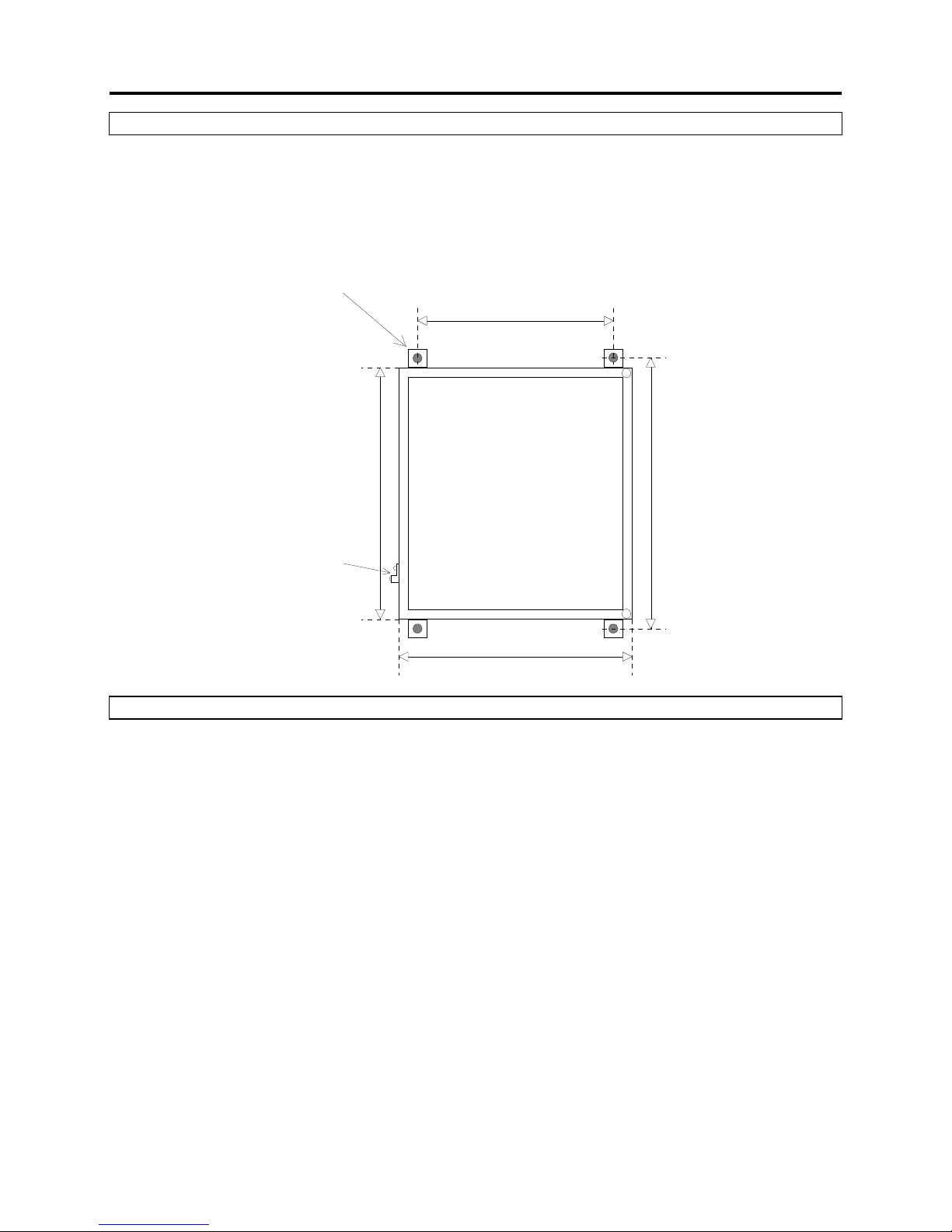
The standard enclosure for the MultiMux is a Hoffman 12x10 fiberglass/polyester NEMA 4 type. The
enclosure can be mounted to a wall or other surface by attaching the 4 supplied mounting tabs to the
bottom of the enclosure using the supplied screws.
The placement of the mounting holes is depicted in the illustration below.
Mounting Hole
(4 places)
8.00"
(203 mm)
12.5"
(318 mm)
Earth Ground Lug
10.5" (267 mm)
12.94"
(329 mm)
2.9 Lightning Protection
If the MultiMux is equipped with the optional lightning protection components then care must be exercised
in the installation to maximize their effectiveness. Specifically, an effective earth ground must be attached
to the MultiMux terminal board.
If the MultiMux was ordered in an enclosure with the lightning protection components then there will be a
ground lug on the side of the enclosure as shown in the illustration above. Attach a large gauge copper
wire (6-12 AWG) from the lug to a suitable earth ground, either a copper stake driven into the earth or a
known electrical system earth ground.
Copper earth ground stakes and connecting wire are available from Canary Systems.
Page 12
Section 2 – MultiMux Operation and Installation 12
2.10 DaisyMux Operation
DaisyMux is a special operation mode where all of the signals are shared between 2 or more
multiplexers. The MultiMux supports up to 8 multiplexers used in a DaisyMux configuration and the
switching mode is ALWAYS 16 Channel.
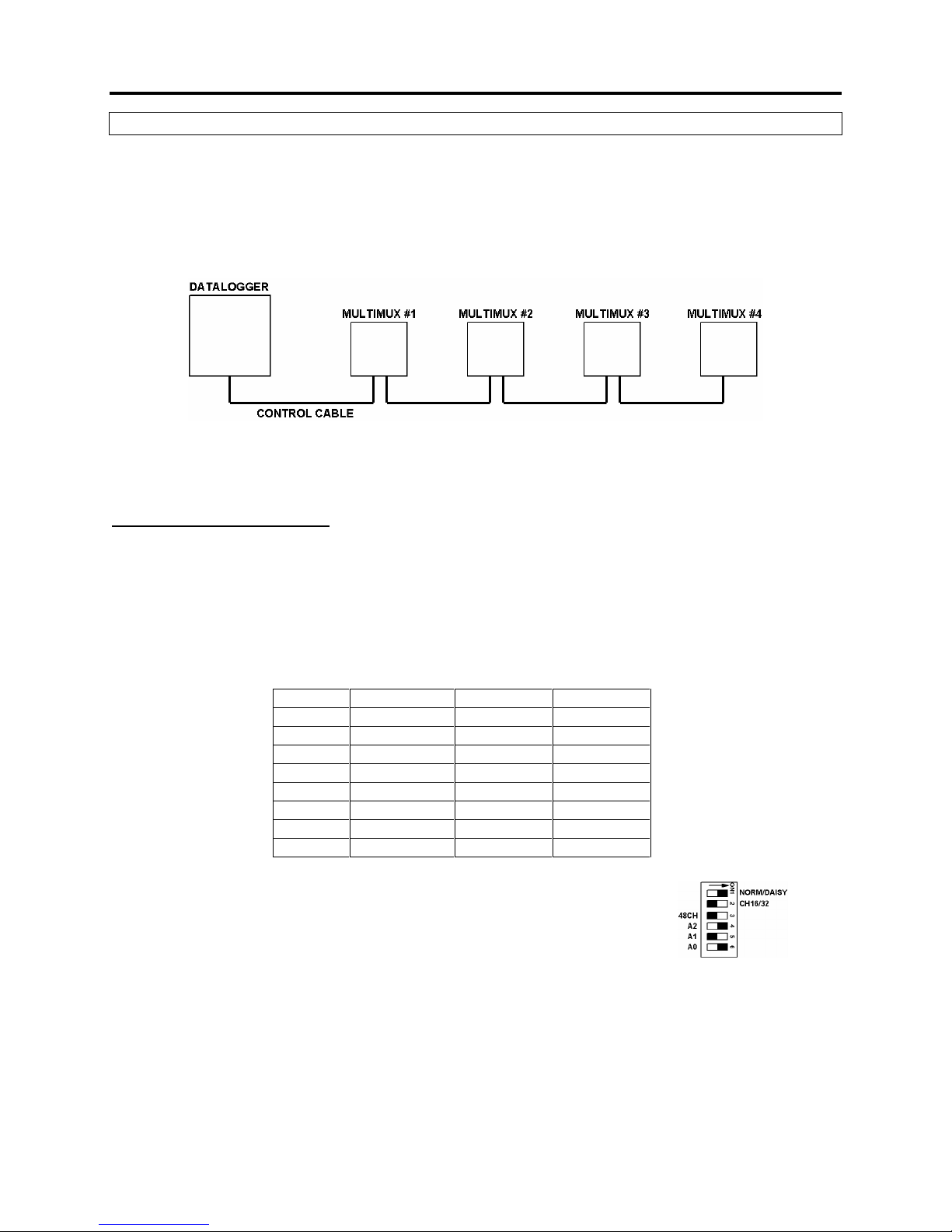
The advantage with the DaisyMux configuration is that a single cable may be used to connect a string of
MultiMux multiplexers together, as shown in the diagram below.
There are 2 configuration issues to deploy the DaisyMux, the DIP switch settings of the MultiMux and the
MultiLogger Software configuration.
MultiMux DIP Switch Settings
On the MultiMux are 3 switches in the DIP switch array, labeled A2, A1 and A0, that control the address
of the multiplexer, this address ranges between 0 and 7 in binary values, or between 1 and 8 in terms of
the multiplexer number. These determine which section of channels will be activated, i.e. the MultiMux
configured with address 0 with be active for channels 1-16, the MultiMux with address 1 will be active for
channels 17-33, etc.
The following table illustrates the range multiplexer numbers and corresponding DIP switch settings.
Mux# A2 – SW4 A1 – SW5 A0 – SW6
1 OFF OFF OFF
2 OFF OFF ON
3 OFF ON OFF
4 OFF ON ON
5 ON OFF OFF
6 ON OFF ON
7 ON ON OFF
8 ON ON ON
For example, the DIP switches for MultiMux #6 should be configured as shown:
NOTE: ONLY 16 channel mode is supported by the DaisyMux!
Page 13
Section 2 – MultiMux Operation and Installation 13
MultiLogger Software Configuration
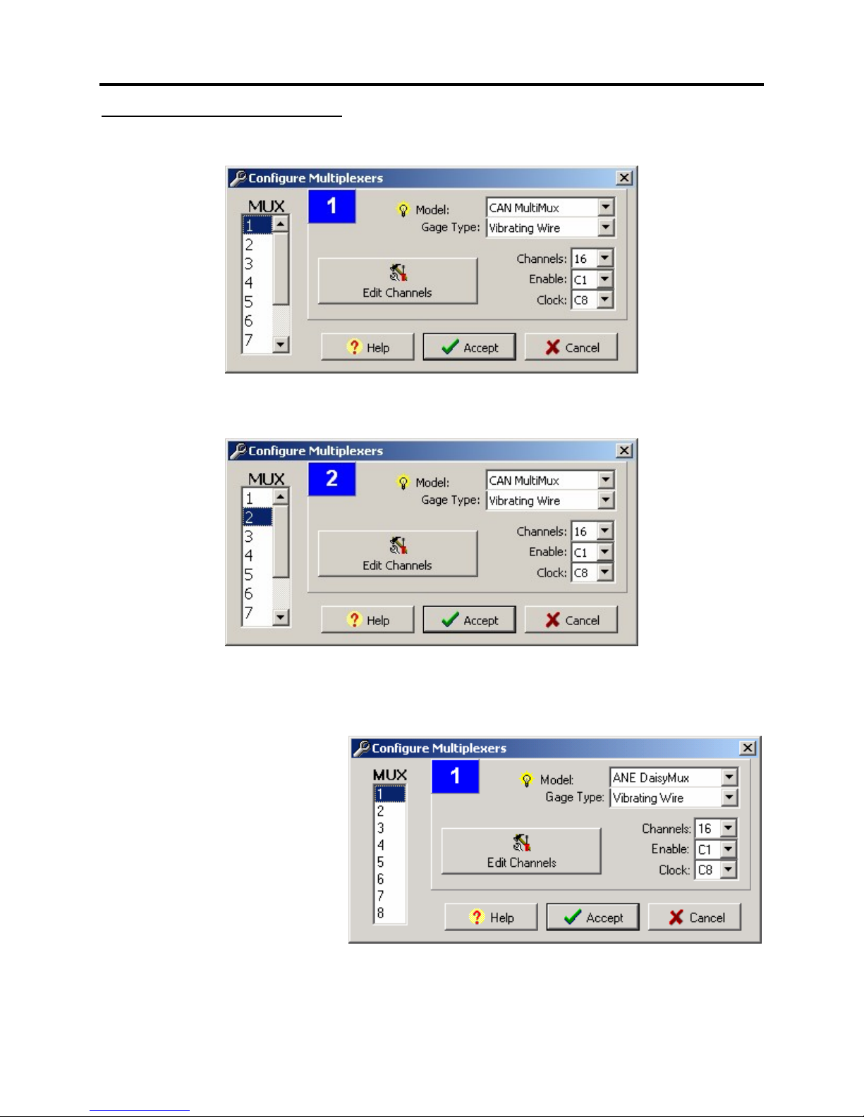
Multiplexers are configured using the Program | Multiplexers form, as illustrated.
To configure DaisyMux operation you would simply specify an Enable port that matches all of the
multiplexers in the series. For example, multiplexer #2 would be configured as shown below.
When MultiLogger builds the datalogger program it will note that the Enable setting is the same for the 2
(or more) multiplexers, it will not lower the Enable line, which would effectively reset the multiplexers,
between the multiplexers.
NOTE: This functionality was
supported beginning with version
2.1.1 of the MultiLogger Software.
Prior to version 2.1.1 you were
required to use the special ANE
DaisyMux Model (as shown) to
support the DaisyMux
configuration. If your version of
software is outdated it is
recommended that you upgrade,
contact Canary Systems or your
software vendor to obtain the
access information for software
upgrades. Software upgrades are
available through a support contract.
Page 14
Are the switched leads
wiring correct for the
No
No
Attach 12V and G
Are the Enable and
Attach Enable & Clock
No
No
wiring?
No
Adjust the wiring for the
Adjust the software
No No No
water or
No
Note: See the MultiSensor
Interface User's Guide or
User's Guide for wiring
Section 3 – Troubleshooting 14
3.1 Troubleshooting Flowchart
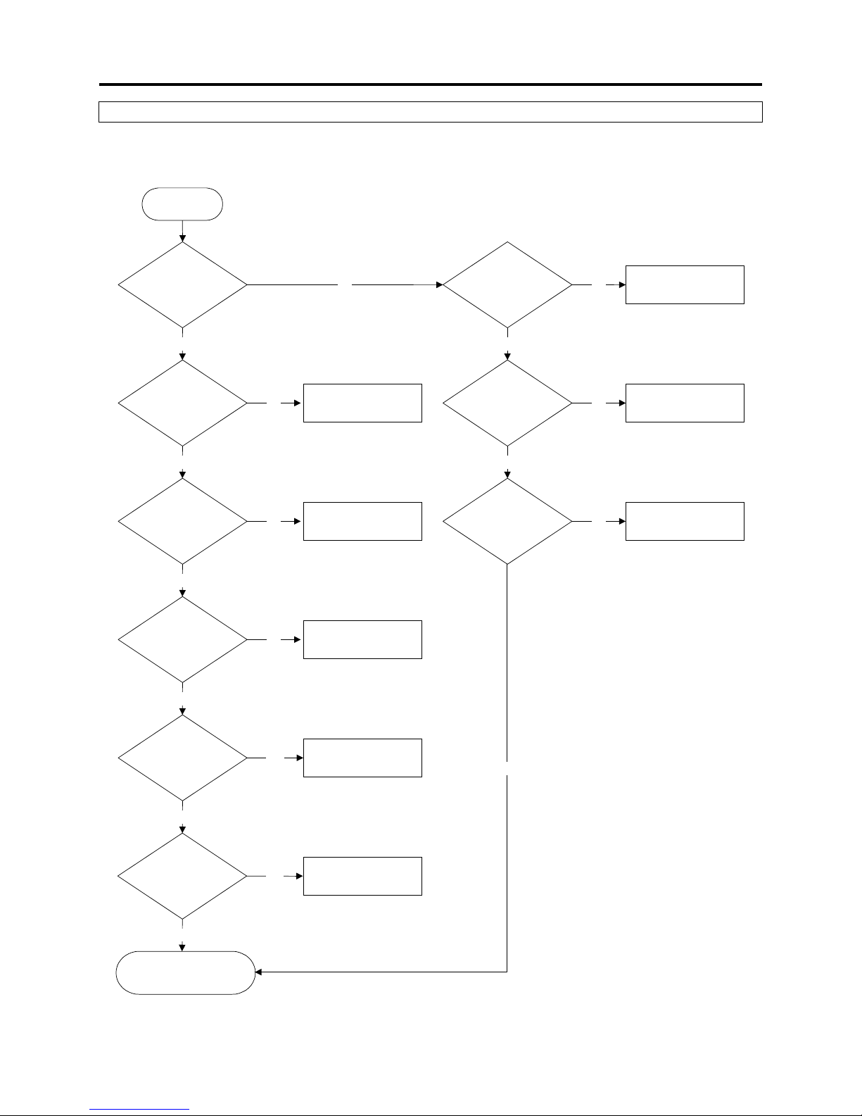
If you cannot obtain readings using the MultiMux or the readings are unstable then see the
troubleshooting flowchart below for help in determining the nature of the problem.
Start
Does the MultiMux
advance through the
channels?
Yes
connected?
Yes
Is the
sensor leads?
Yes
Do the
software settings match
the sensor type and
Connect the leads
type of sensor used
MultiLogger Software
diagrams.
settings
Is 12V and G
connected to the
MultiMux?
Yes
Clock lines connected
to the control ports?
Yes
Do the software
settings for the Enable
and Clock lines match
the connections?
lines
Match software and digital
I/O connections
Yes
Is there a source of
electrical noise nearby?
Do the
circuit boards show
Call Canary Systems for
further assistance
other
contamination?
Yes
Yes
Remove the noise source
or move the MultiMux
Clean the circuit boards
Yes
 Loading...