

Page 1
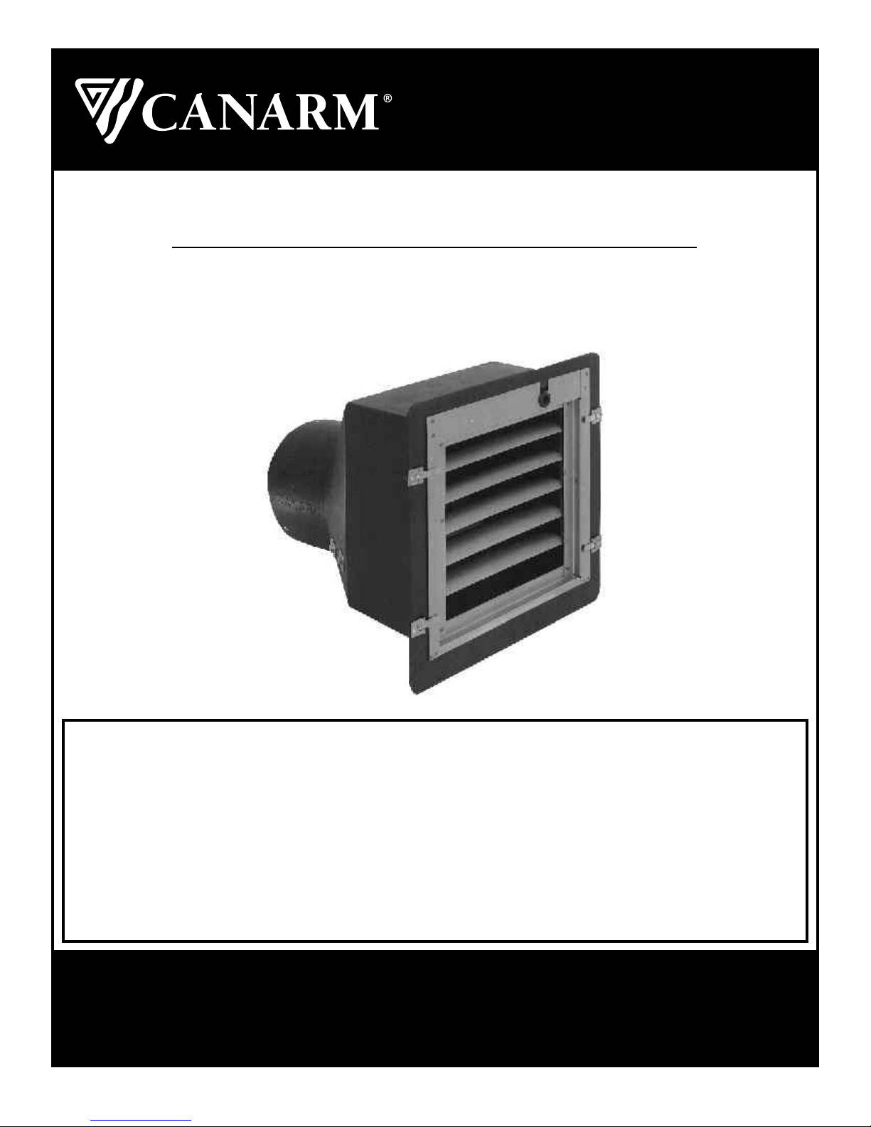
PLF Series Fans
Instruction Manual
READ AND SAVE THESE INSTRUCTIONS
CANARM Ltd. warrants every new fan to be free of defects in material and workmanship, to the extent
that, within a period of one year from the date of purchase CANARM Ltd. shall either repair or replace
at CANARM’s option, any unit or part thereof, returned freight prepaid, and found to be defective.
This warranty does not include any labour or transportation costs incidental to the removal and
reinstallation of the unit at the user’s premises.
Components repaired or replaced are warranted through the remainder of the original warranty
period only.
This warranty applies to the original purchaser-user only; it is null and void in case of alteration,
accident, abuse, neglect, and operation not in accordance with instructions.
NOTICE: No warranty claims will be honored by CANARM Ltd. unless prior authorization is obtained.
Installation or Product problems? Do not return to store of purchase.
Contact Canarm Service at 1-800-265-1833 (CANADA) 1-800-267-4427 (U.S.A.)
1-800-567-2513 (EN FRANCAIS) Monday to Friday 8:00 - 5:00pm e.s.t.
M0017 - Rev.5-Rev Date: 22/04/03
WARRANTY
Page 1 of5
Page 2
User’s Guide for All PLF Series Models
Congratulations on the purchase of your new High Performance Plastic Fan. This fan is made of materials that ensure
long lasting performance and is designed with features that make it one of the most efficient and easy to use and care
for fans available today.
Your fan comes completely assembled except for the metal turn clips that can be quickly assembled into the pre-drilled
holes around the outside flanges of the fan. All fans are tested for proper operation before leaving the factory. Your fan
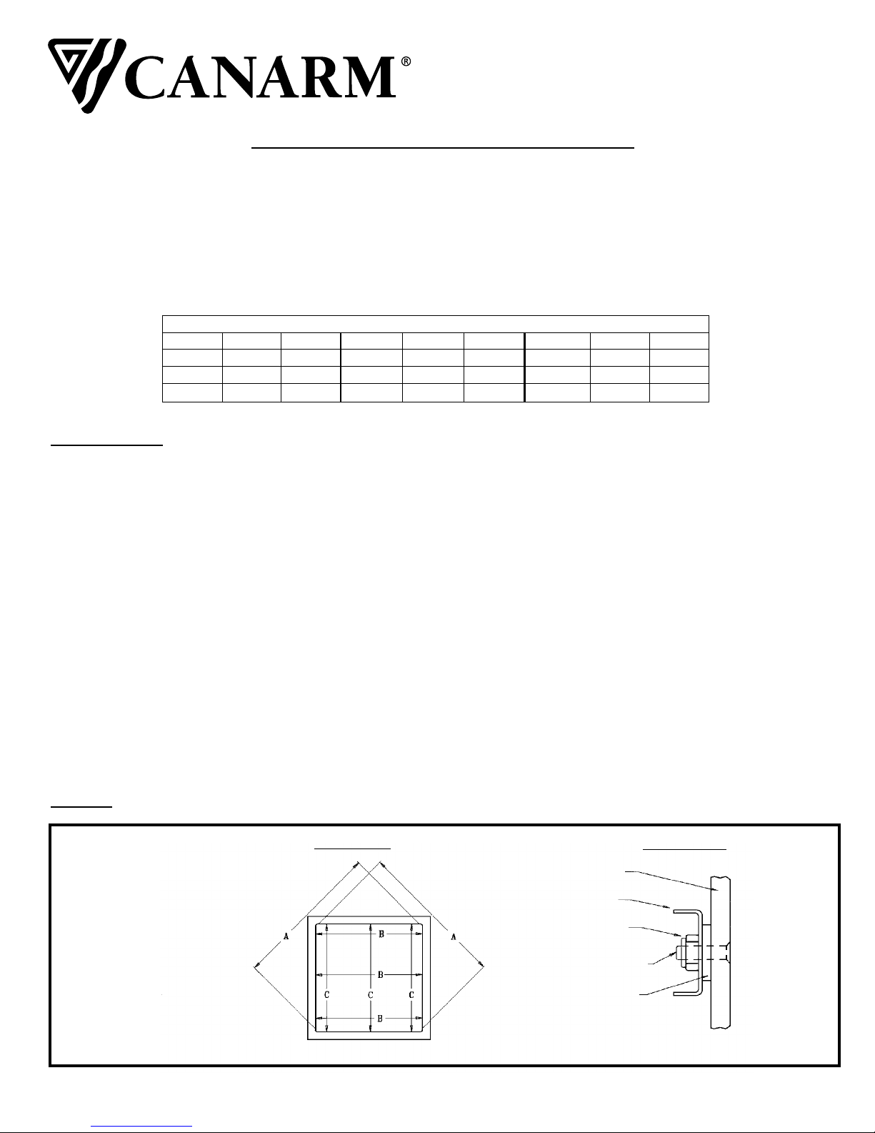
should be installed into a wood frame. See Chart #1 for dimensions.
Chart #1
Rough Inside Opening Frame Dimension
Model H W
PLF09 15.00" 15.00"
PLF12 15.00" 15.00" PLF18 21.25" 21.25"
PLF14 17.25" 17.25" PLF20 23.25" 23.25"
INSTALLATION
PLF36 Models
Remove the fan from the shipping pallet by removing the 6 screws holding the fan to the pallet. A hardware bag is
secured to the motor support arm. The hardware bag contains 8 turn clips, 8 nylon washers, 8 10-24 x 3/4" stainless
steel screws, and 8 nylon insert nuts. This hardware is for the turn clips that hold the shutter assembly in place.
Model H W Model H W
PLF16 19.25" 19.25" PLF24 27.25" 27.25"
PLF36 40.25" 40.25"
PLF48 52.25" 52.25"
Assemble the 8 turn clips to the pre-drilled holes. There are 3 holes down each side flange and 1 on each of the top
and bottom flanges. For each of the 8 turn clips insert the screw through the hole from the back of the flange, slide on
a nylon washer, then the clip, and thread the nut. Tighten the turn clips with a Phillips screw driver and a 3/8" socket
wrench. (see Figure 1-b).
PLF09 to PLF24 Models
Simply remove the fan from the carton and proceed to next section.
All Fan Models
With the shutter removed, slide the fan into the framed opening. Push the fan up against the top of the frame to be sure
the fan slopes downward for drainage to the outside. Secure the 4 corners with lag bolts. Secure the 4 sides being
sure the inside dimensions of the fan are consistent between flanges so that clips and shutters will operate correctly.
(see Figure 1-a) This will also ensure that the orifice, is not deformed which may cause the blade to hit the tunnel of the
fan.
Caution: If using expanding foam to insulate, make sure expansion pressure does not damage the housing.
Inside View of Fan
-BeSure All Similar
Dimensions Are Equal
When Mounting Fan
Mounting
Fan Flange
Turn Clip
Clip Detail
Hex Locknut
Machine Screw
Figure 1-a
M0017 - Rev.5-Rev Date: 22/04/03
Nylon Washer
Figure 1-b
Page 2 of5
Page 3
ELECTRICAL CONNECTIONS
If your fan is not provided with a cord, use the following procedure to wire the fan.
WARNING
!
WARNING: BE SURE POWER IS OFF AT THE ELECTRICAL PANEL BEFORE
HighVoltage,
disconnect power
beforeser vicing.
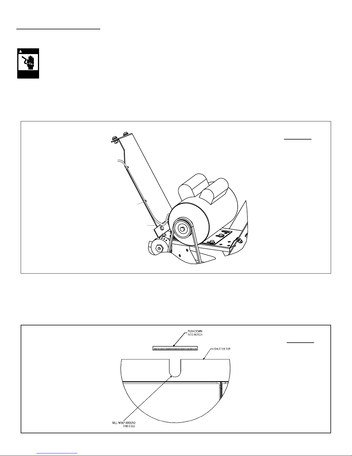
When bringing power to the fan, water-tight cable and connectors should be used. The cable will be brought to the
motor through the slot provided in the top of the shutter and allowances in length of cable should be considered. Bring
the cable down below the height of the motor then back up to the connector in the side of the motor. This will prevent
moisture from running down the cable into the motor. On some models, there are holes punched along the lengths of
the arms. It is recommended that you use cable ties provided in hardware bag to attach cable to arm (see Figure 2).
Figure 2
Out through
slot in shutter
Cable ties
to hold cable
in place
Cable is lower
than connection
box for water
drainage
Make sure the cord will not interfere with the blade or louvers. To protect the cable, place the grommetting supplied
over the shutter notch edges (see Figure 3). The motors supplied with these fans are dual voltage 120/240V (except
for 48" Direct Drive - 240 volt only), but 240V is recommended to reduce power consumption (Note: Fans are factory
pre-wired for 240V. Follow motor nameplate directions if 120V is desired).
Note: Some fans are available with 3 phase motors. These are not factory pre-wired.Follow Chart #2 for wire sizes.
Wiring and motor specification information can be found on the motor nameplate.
Figure 3
M0017 - Rev.5-Rev Date: 22/04/03
Page 3 of5
Page 4
Chart #2
TableA-Minimum Wire Sizes for Three-Phase Motors
Motor 25 to 50 Feet 100 Feet 150 to 200 Feet
HP 200V 230V 460V 200V 230V 460V 200V 230V 460V
1/8 14(18)* 14(18)* 14(18)* 14(18)* 14(18)* 14(18)* 14(16)* 14(16)* 14(18)*
1/6 14(18)* 14(18)* 14(18)* 14(18)* 14(18)* 14(18)* 14 14(16)* 14(18)*
1/4 14(18)* 14(18)* 14(18)* 14(16)* 14(18)* 14(18)* 14 14 14(18)*
1/3 14(18)* 14(18)* 14(18)* 14(16)* 14(16)* 14(18)* 12 14 14(18)*
1/2 14(16)* 14(18)* 14(18)* 12 14(16)* 14(18)* 10 12 14(18)*
3/4 14(16)* 14(16)* 14(18)* 12 14 14(18)* 10 10 14(16)*
11414(16)* 14(18)* 12 12 14(18)* 8 10 14(16)*
1-1/2 12 14 14(18)* 10 10 14(16)* 6 8 14
2121214(18)* 8 10 14(16)* 6 6 12
3101214(18)* 6 8 14 4 6 12
TableB-Minimum Wire Sizes for Single-Phase Motors
Motor 25 to 50 Feet 100 Feet 150 to 200 Feet
HP 200V 230V 460V 200V 230V 460V 200V 230V 460V
1/8 14(18)* 14(18)* 14 14(18)* 12 14(18)* 10 8 14
1/6 14(16)* 14(18)* 12 14(18)* 10 14(16)* 6 6 12
1/4 14 14(18)* 10 14(16)* 8 14 6 4 10
1/3 14 14(18)* 10 14(16)* 8 14 6 4 10
1/2 12 14(18)* 8 14 6 12 4 3 8
3/4 10 14(16)* 6 12 4 10 2 1 6
11014(16)* 6 12 4 10 2 1 6
1-1/2 8 14 6 12 3 8 1 1/0 6
281441028 1/0 2/0 4
36123 81/0 6 2/0 4/0 3
Note:
• NEC Article 310-5-*Minimum conductor size for general wiring at 115-440VAC is number 14AWG.
• Above wire sizes based on approximate 5% voltage drop during starting; copper conductors; and 75C type THHW, THW, THWN, RH, RHW
insulation etc. For aluminum wire, increase two wire size steps minimum. See NEC Article 310 for ampacities af aluminum conductors.
• Type S, SO, SJ, SJO, etc flexible cable wire sizes. See NEC Article 400 for ampacity.
OPERATION
Fans are designed to operate with simple on/off switches, or can be wired into sophisticated controls. Some fan models
are designed to run at variable speed while others are single speed only. Varying a single speed fan will cause the motor
to fail.
Fan labels should indicate whether or not fan is variable speed. If unsure contact a Canarm representative with the fan
model number at our head office.
WARNING: Variable speed fans should have the minimum speed set to open the fan louvers a minimum of 1"
to ensure proper motor cooling and prevent premature motor failure.
MAINTENANCE
WARNING
!
WARNING: Motors are equipped with automatic overload protection and may restart without warning.
Always disconnect power before attempting to service.
Moving parts,
disconnect power
before servicing.
These fans are used in a variety of applications and therefore maintenance schedules will vary. In general no more than
1/16" of dirt build-up should occur on blade, motor, guard, and louvers for proper fan operation and to prevent premature
failure. The complete fan should be washed down on a regular basis to maintain the high efficiency of the fan. Particular
care should be taken to clean louvers, fan blades front and back, and front guards for better air moving performance. The
motor should be kept clean to prevent overheating and premature failure. As with all mechanical equipment scheduled
inspections should include checking that all hardware is secure and blade set screws are tight. We suggest as a minimum,
that this be done after every grow out, in livestock applications.
M0017 - Rev.5-Rev Date: 22/04/03
Page 4 of5
Page 5
BELT DRIVE FAN
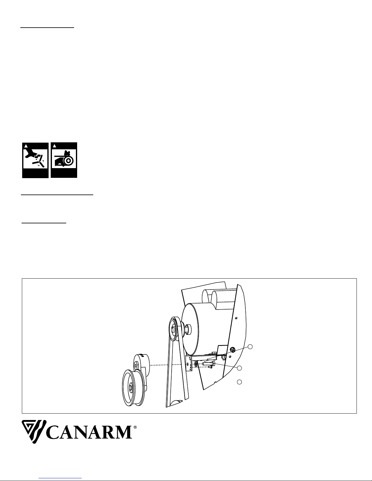
Belt drive fans are equipped with an automatic belt tensioner and cogged v-belt. The rotary tensioner will compensate
for any wear or stretching of the belt. No adjustments should be necessary. Belt will however wear after extensive use.
Fan performance will be sacrificed if worn belt is used. Listen for belt “squeeling” on startup. This would indicate that
the belt requires changing or tightening. Tightening can be done by moving the screw location on the tensioner
bracket. (see figure 3) (Although we recommend replacing the belt).
Lubrication: Belt drive fans are provided with bearing blocks that are pre-lubricated & sealed. They have a double
contact seal and steel slinger that prevents most contamination. However, since the bearings are to operate in very
damp and dirty conditions, re-lubrication is recommended. The grease fitting of the unit should be carefully cleaned
before use and the grease should be introduced slowly. Under normal conditions, the bearings only need re-lubrication
every 3 years. Nonetheless, we recommend that each bearing receive one pump from a grease gun (or until fresh
grease is pushed out), every time the unit is washed down (especially if detergent is used.)
Note: Use NLGI2 lithium base grease to ensure compatibility with original grease.
Caution: Do not use pneumatic grease guns. Slowly introduce grease with manual gun otherwise bearing seals will be
destroyed.
WARNING
!
WARNING
!
WARNING: Motors are equipped with automatic overload protection and may
restart without warning. Always disconnect power before attempting to service,
Moving parts,
disconnect power
before servicing.
Moving parts,
disconnect power
before servicing.
REPLACEMENT PARTS
See attached appendices for replacement parts.
ACCESSORIES
Canarm provides a full line of controls from simple on/off thermostats to sophisticated multiple staging controllers and
PC based controllers. Winter covers are available for colder climates where the fan is shut down for the winter.
Performance enhancing cones are available for 24" to 48" sizes that boosts air moving performance and efficiency by
approximately 8% for PLF48, 10% for PLF36 fans, and 15% for PLF24 fans. Weather Hoods are available for 9” to 24”
models.
or removing shutter
Figure 3
Adjusting Belt Tensioner
M0017 - Rev.5-Rev Date: 22/04/03
1 Remove bolt
2 Change screw hole placement. Moving screw
towards belt will increase tension.
3 Use screw from step 2 as pin location for
tensioner. Reassemble bolt from step 1.
Note: Remove belt before making adjustments.
CANARM LTD. CANARM LTEE.
2157 PARKEDALE AVENUE 8500 RUE GRENACHE
BROCKVILLE, ONTARIO K6V 5V6 ANJOU, QUEBEC H1J 2B1
TELEPHONE: (613) 342-5424 TELEPHONE: (514) 353-2255
FAX: 1-800-263-4598 FAX: (514) 353-2522
E-MAIL: [email protected] E-MAIL: [email protected]
Page 5 of 5
Page 6
4
2
1
8
5
6
7
3
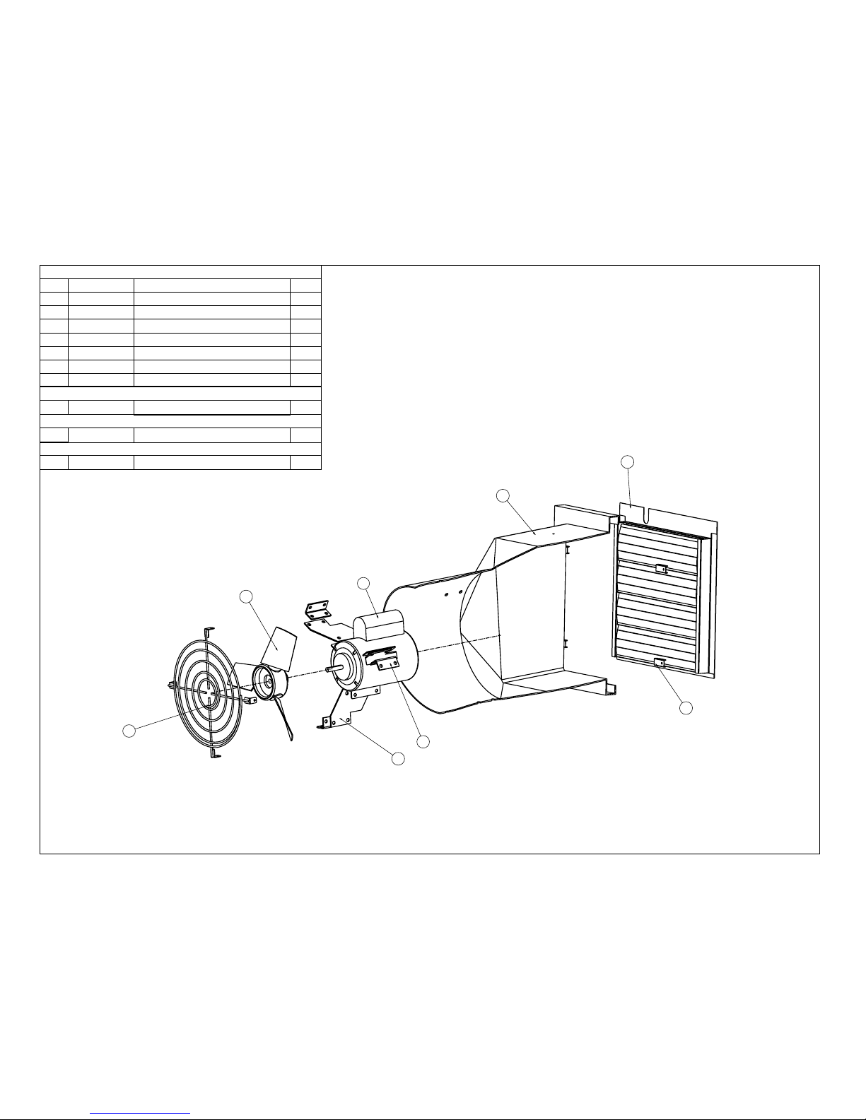
14" Direct Drive
PLF 14-EVD
PLF 14-EVDL
PLF 14-EURO
1
G1028
Turn Clip
4
2
G1050
PLF Mount Arm Link Bracket
3
3
G1051-14
PLF Motor Arm
3
4
G1910-14
14" Fan Guard
1
5
G2809-14B
PLF Housing
1
6
G2900-14
14" Shutter Assembly
1
7
G2950-14
14" 3/45 Rotair Blade
1
No.
Component
Description
Qty.
8
P1164-E
1/4 HP, 1625 RPM, 115/230V, 3.6/1.8A
1
8
P1168-E3
1/4 HP, 1625 RPM, 115/230V
1
8
P1155-E
Leeson 1/4 HP, 1625 RPM, 115/230V
1
Page 7
4
2
1
8
5
6
7
3
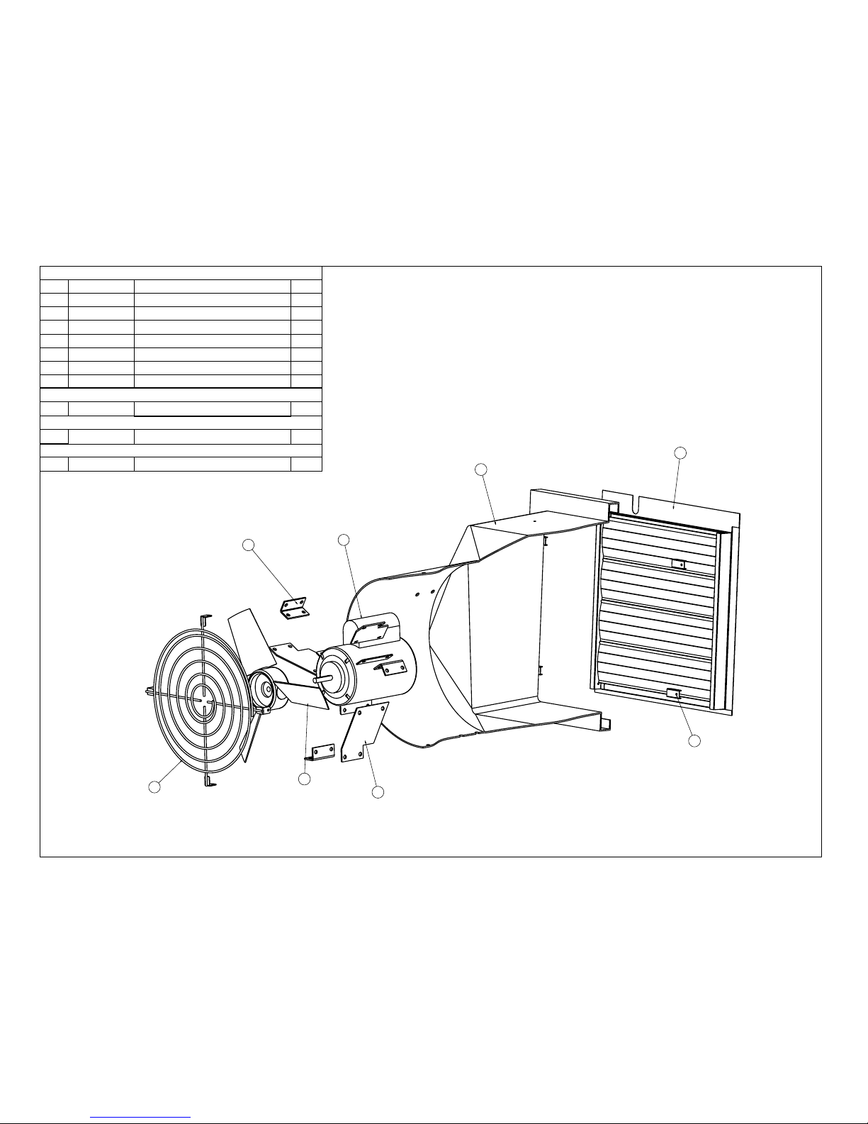
16" Direct Drive
PLF 16-EVD
PLF 16-EVDL
PLF 16-EURO
1
G1028
Turn Clip
4
2
G1050
PLF Mount Arm Link Bracket
3
3
G1051-16
PLF Motor Arm
3
4
G1910-16
16" Fan Guard
1
5
G2809-16B
PLF Housing
1
6
G2900-16
16" Shutter Assembly
1
7
G2950-16
16" 3/45 Rotair Blade
1
No.
Component
Description
Qty.
8
P1164-E3
1/4 HP, Max.1625 RPM, 115/230V
1
8
P1168-E
1/4 HP, 1625 RPM, 115/230V
1
8
P1155-E
Leeson 1/4 HP, 1625 RPM, 115/230V
1
Page 8
4
2
8
5
6
1
7
3
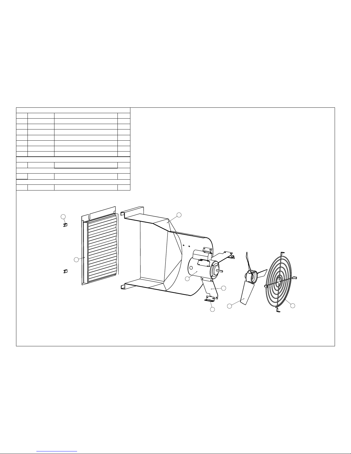
18" Direct Drive
PLF 18-FVD
PLF 18-FVDL
PLF 18-EURO
1
G1028
Turn Clip
4
2
G1050
PLF Mount Arm Link Bracket
3
3
G1051-18
PLF Motor Arm
3
4
G1910-18
18" Fan Guard
1
5
G2809-18B
PLF Housing
1
6
G2900-18
18" Shutter Assembly
1
7
G2950-18
18" 3/4 Rotair Blade
1
No.
Component
Description
Qty.
8
P1164-F3
1/3 HP, Max.1625 RPM, 115/230V, 3.6/1.8A
1
8
P1168-F
1/3 HP, 1625 RPM, 115/230V
1
8
P1155-F
Leeson 1/3 HP, 1625 RPM, 115/230V
1
Page 9
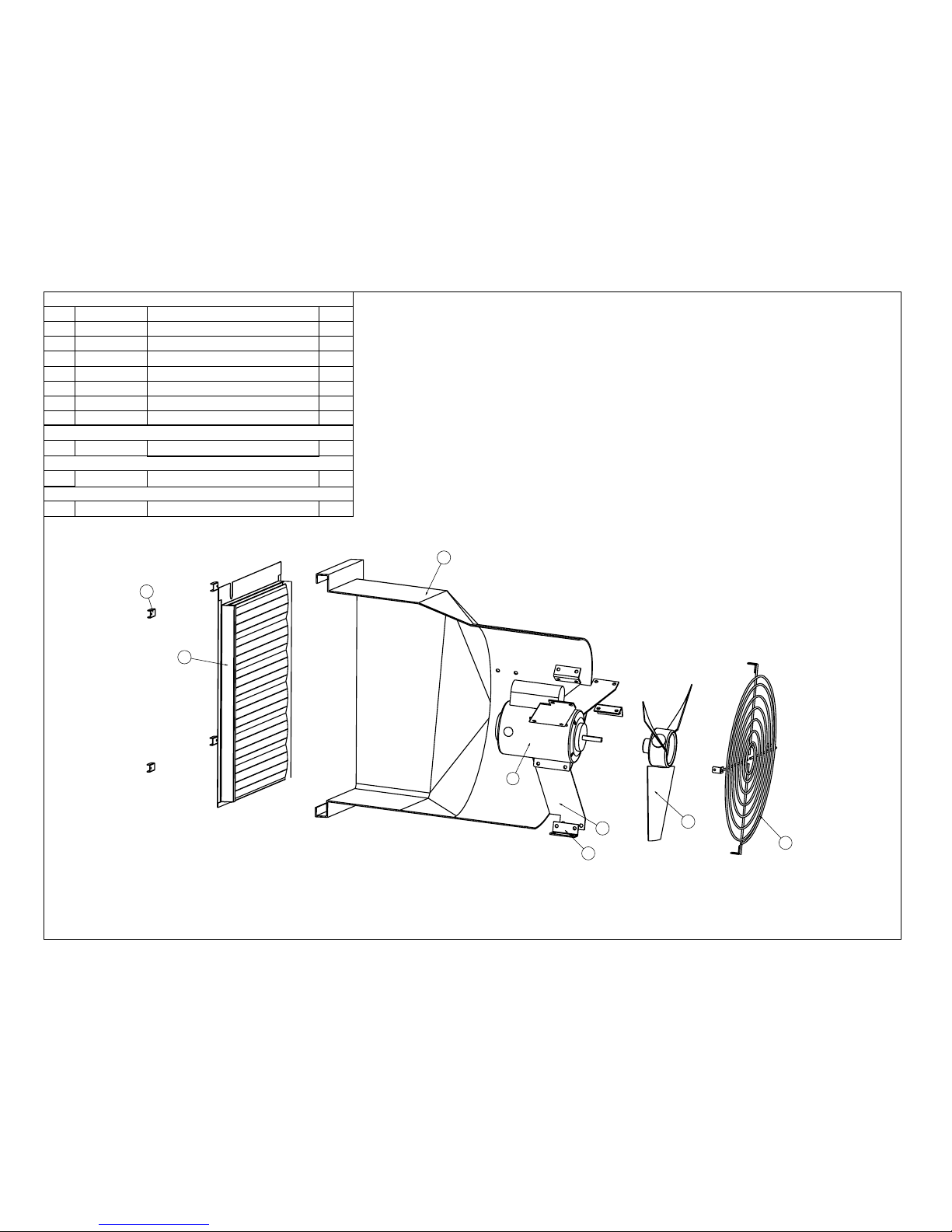
4
2
8
5
6
1
7
3
20" Direct Drive
PLF 20-FVD
PLF 20-FVDL
PLF 20-EURO
1
G1028
Turn Clip
4
2
G1050
PLF Mount Arm Link Bracket
3
3
G1051-20
PLF Motor Arm
3
4
G1910-20
20" Fan Guard
1
5
G2809-20B
PLF Housing
1
6
G2900-20
20" Shutter Assembly
1
7
G2950-20
20" 3/45 Rotair Blade
1
No.
Component
Description
Qty.
8
P1164-F3
1/3 HP, Max.1625 RPM, 115/230V, 3.6/1.8A
1
8
P1168-F
1/3 HP, 1625 RPM, 115/230V
1
8
P1155-F
Leeson 1/3 HP, 1625 RPM, 115/230V
1
Page 10
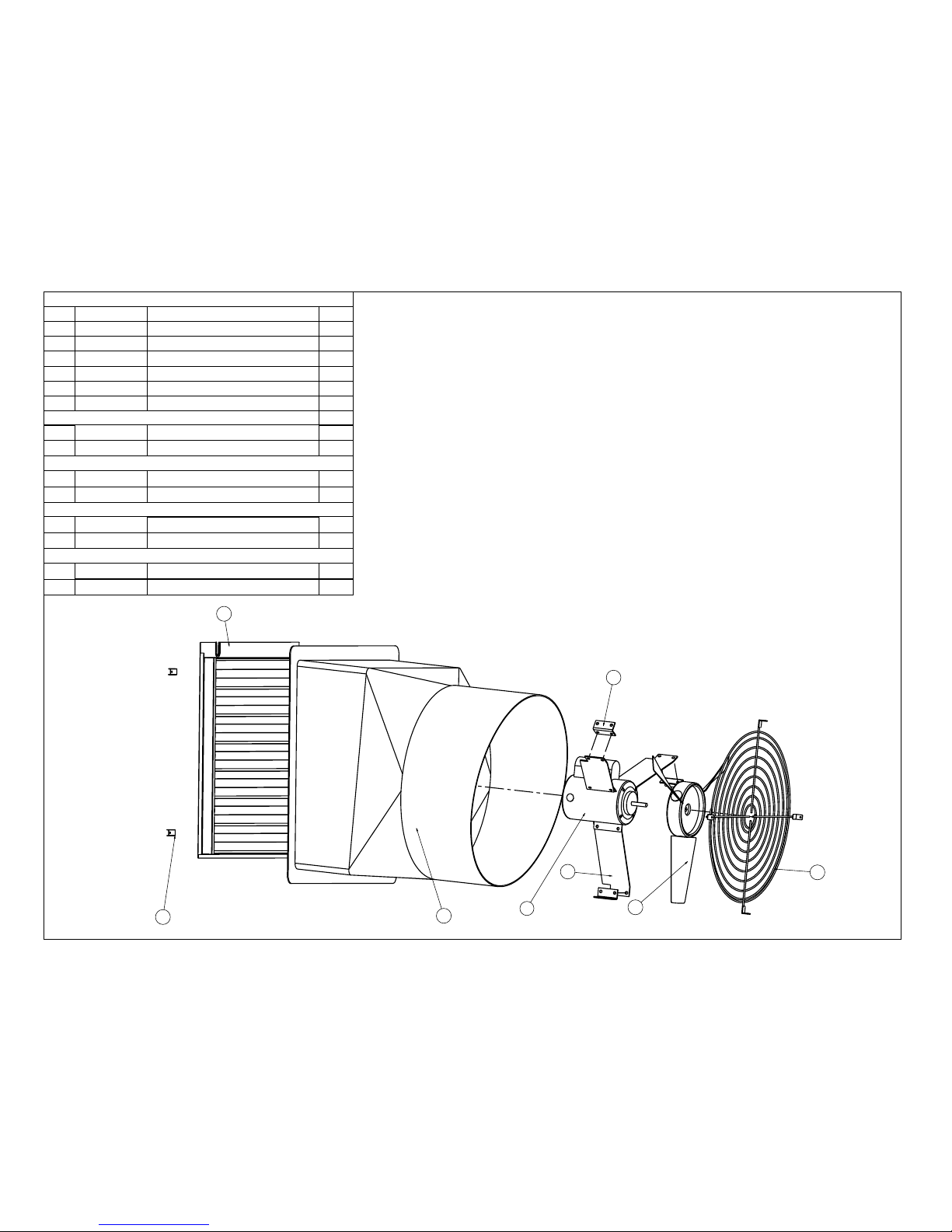
4
2
1
8
5
6
7
3
24" Direct Drive
PLF 24-M
PLF 24-GVD
1
G1028
Turn Clip
4
2
G1050
PLF Mount Arm Link Bracket
3
3
G2983
24" Shutter Assembly
1
4
G1051-24
PLF Motor Arm
3
5
G1910-24
24" Spiral Guard
1
6
G2809-24B
PLF Housing
1
7
P1166-F3
1/3 HP, 1100 RPM, 115/230V
1
No.
Component
Description
Qty.
8
G2950-24M 1
7
P1168-G
1/2 HP, 1625 RPM, 115/230V
1
8
G2948-24338
Rotair Blade 24"/6/38
1
Rotair Blade 24"/6/45
PLF 24-GVDL
7
P1168-G
1/2 HP, 1625 RPM, 115/230V
1
8
G2948-24338
Rotair Blade 24"/6/38
1
PLF 24-EURO
7
P1155-G
Leeson 1/4 HP, 1625 RPM, 115/230V
1
8
G2948-24338
Rotair Blade 24"/6/38
1
Page 11
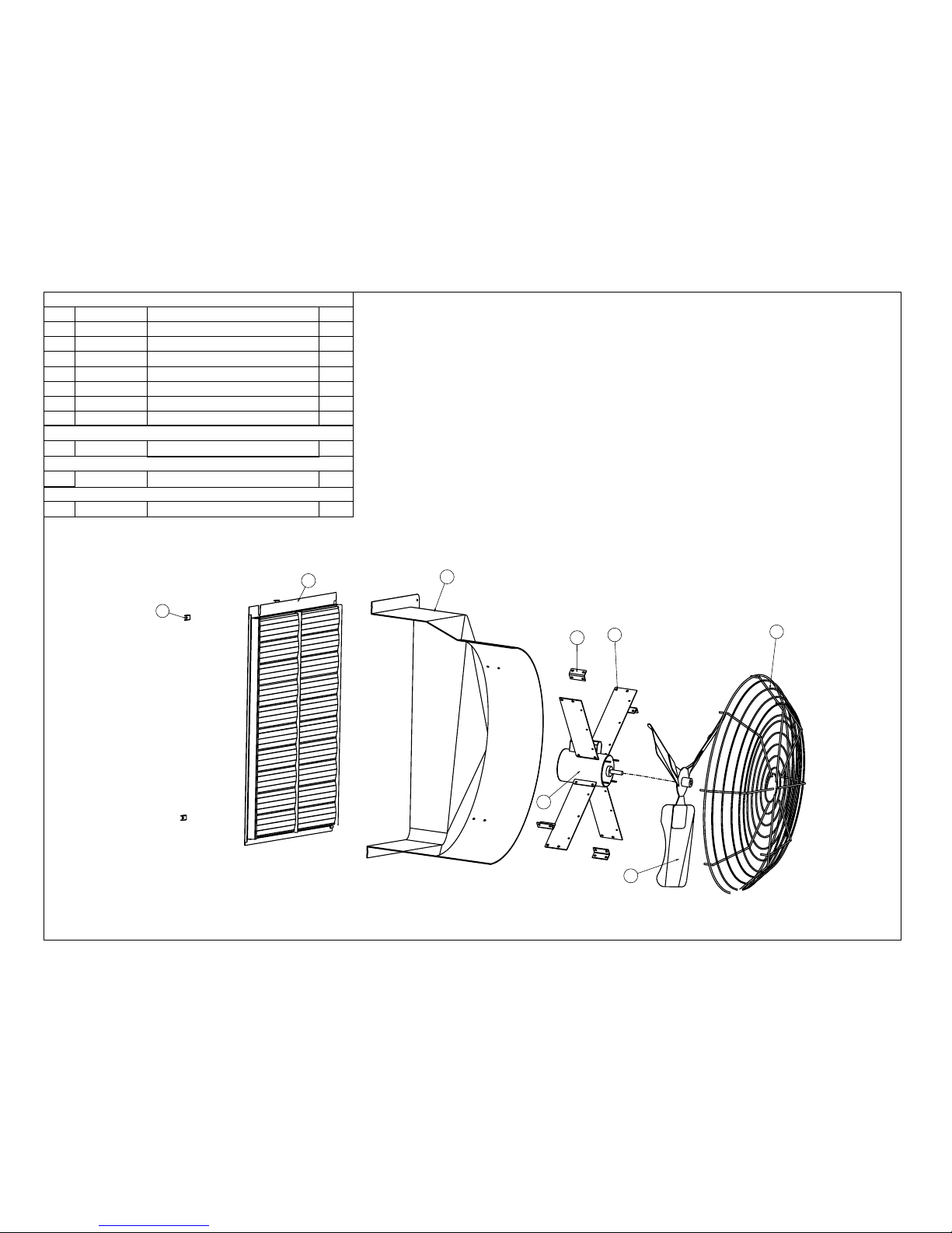
4
2
1
8
5
6
7
3
36" Direct Drive
PLF 36-M
PLF 36-MP
PLF 36-MPVS
1
G1028
Turn Clip
4
2
G1050
PLF Mount Arm Link Bracket
4
3
G1051-36
PLF Motor Arm
4
4
G1658-36GV
36" Galv. Shutter Assembly
1
5
G1900-36
PLF36 Spiral Guard
1
6
G2809-36B
PLF Housing
1
7
P1170-36DP
1/2 HP, 825 RPM, 4 Lug Mount
1
No.
Component
Description
Qty.
8
P3006-36D
36" S.S. Blade 3/25
1
8
P3005-36D
36" Galv. Blade 3/25
1
8
P3005-36DV
36" Galv. Blade 3/19
1
Page 12
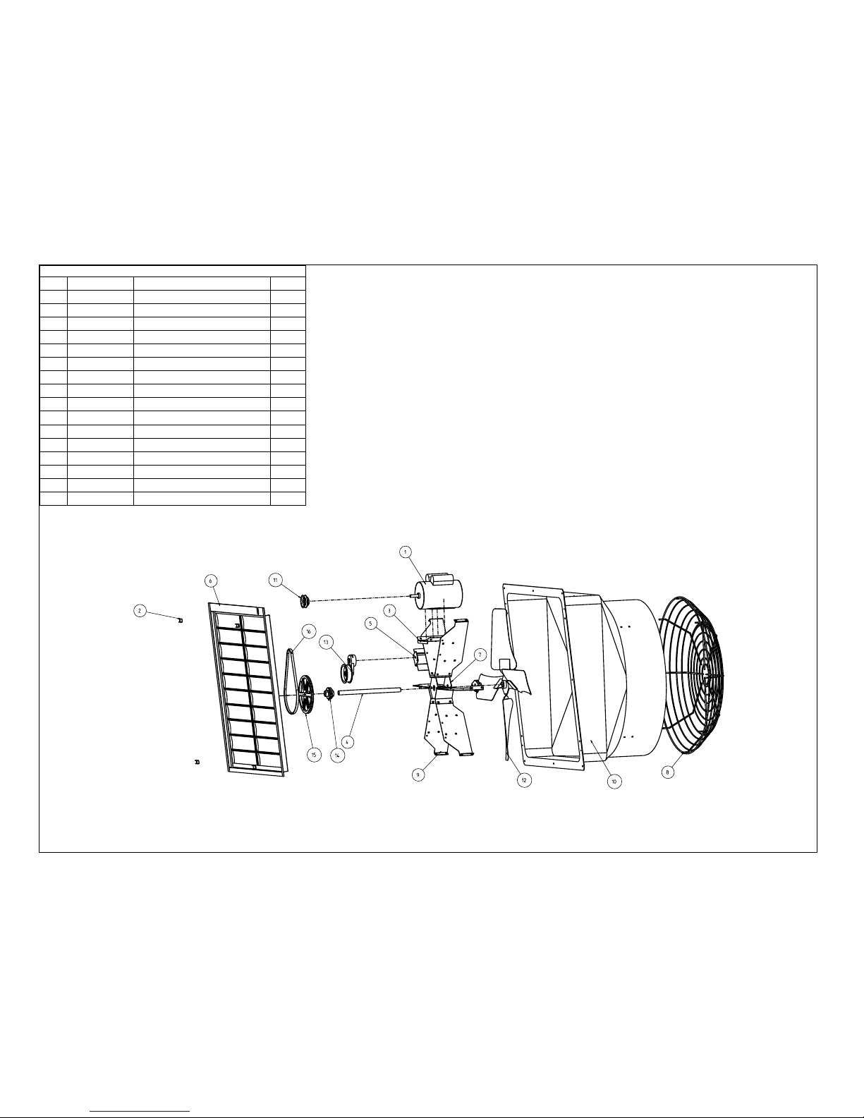
36" Belt Drive
1
P1174-48BGE
1 HP, 1725 RPM, 115V, Reversable
1
2
G1028
Turn Clip
4
3
G1883
Motor Mount Bracket
1
4
G1885
1x14.125 B.D. Shaft-6Lug Mount
1
5
G1939
Rotary Tensioner Mount Bracket
1
6
G1658-36V
36 GV. Shutter Assembly
1
No.
Component
Description
Qty.
7
G1896-GV-3
Bearing Mount Case
1
8
G1900-36
PLF Guard
1
9
G2458-36
Motor Mount Arm
6
10
G2809-36B
PLF Housing
1
11
P2020-45
Motor Pulley
1
12
P3030-36B
36" BD Blade 4/43, Galv
1
13
P9600
Rotary Tensioner
1
14
P2002-216
Bearing-2Bolt Flange Mount
1
15
P2010-9
9" Pulley
1
16
P2034-AX38
Cogged V-Belt AX 38
1
 Loading...