

Page 1

DS 90
/
DS 90 X
2015
Operator’s
Guide
Includes
Safety, Vehicle
and
Maintenance Information
(All countries except Canada/United States)
TM
DS 90
TM
2015
Read this guide thoroughly. It contains important safety information.
Category Y ATV, always follow this age recommendation under adult supervision:
Age 10 or older for DS 90 and DS 90 X. Keep this Operator’s Guide in the vehicle.
2 1 9 0 0 1 5 6 7
DS 90TM X
Original Instructions
Original Instructions
Page 2

WARNING
YOUR VEHICLE CAN BE HAZARDOUS TO OPERATE. A collision or rollover
can occur quickly if you fail to take proper precautions, even during routine
maneuvers such as turning and driving on hills or over obstacles.
For your safety, understand and follow all the warnings contained in this
Operator’s Guide and on the labels on your vehicle. Failure to follow these
warnings can result in SEVERE INJURY OR DEATH!
Keep this Operator’s Guide with the vehicle at all times.
WARNING
Disregarding any of the safety precautions and instructions contained in
this Operator’s Guide,
SAFETY DVD
and on-product labels can res
severe injury including the possibility of death!
The following trademarks are the property of Bombardier Recreational
Products Inc.:
Can-Am™
ult in
DS 90™
XPS™
vmo2015-028 en
®™ and the BRP logo are trademarks of Bombardier Recreational Products Inc. or its affiliates.
©2014 Bombardi
er Recreational Products Inc. and BRP US Inc. All rights reserved.
Page 3

FOREWORD
Dieses Handbuch ist mö gli cherweise i n Ihrer Landessprache
Deutsch
verfügbar. Bitte wenden Sie sich an Ihren Händler oder besuchen Sie:
www.operatorsguide.brp.com.
English
Español
日本語
Français
Nederlands
Norsk
Português
Suomi
This guide may be available in your language. Check with your dealer or
go to: www.operatorsguide.brp.com.
Es posible que este manual esté disponible en su idi oma. Consulte a su
distribuidor o visite: www.operatorsguide.brp.com .
このガイドは、言語によって翻訳版が用意されています。.
ディーラーに問い合わせるか、次のアドレスでご確認ください:
www.operatorsguide.brp.com.
Ce guide peut être disponible dans votre langue. Vérifier avec vo tre
concessionaire ou aller à: www.operatorsguide.brp.com.
Deze handleiding kan beschikbaar zijn in uw taal. Vraag het aan uw dealer
of ga naar: www.operatorsguide.brp.com.
Denne boken kan finnes tilgjengelig på ditt eget språk. Kontakt din
forhandler eller gå til: www.operatorsguide.brp.com.
Este manual pode estar disponível em seu idioma. F
concessionária ou visite o site: www.operatorsguide.brp.com.
Käyttöohjekirja voi olla saatavissa omalla kielelläsi. Tarkista jälleenmyyjältä
tai käy osoitteessa: www.operatorsgui
de.brp.com
ale com sua
Svenska
Denna bok kan finnas tillgäng lig på ditt språk. Kontakta din återförsäljare
eller gå till: www.operatorsguide.brp.com.
Congratulations on your purchase of a
new Can-Am™ ATV. It is backed by the
BRP warranty and a network of authorized Can-Am dealers ready to p rovide
the parts, service or accessories you
may require.
Your dealer is committed to your satisfaction. He has taken training to perform the initial setup and inspection of
your vehicle, as well as completed the
final adjustments before you took possession. If you need more complete
servicing information, please ask your
dealer.
At delivery, you were also informed of
the warranty coverage and signed the
PREDELIVERY CHECK LIST
to ensure
your new vehicle was prepared to your
entire satisfaction.
Know Before you Go
To learn how to reduce the risk for you
or bystanders being injured or killed,
read this Operator's Guide before you
operate the vehicle:
Also, read all safe ty labels on your ATV
and watch your
Failure to follow th e warnings contained in th is Operator's Guide ca n
result in SERIOUS INJURY or DEATH.
SAFETY DVD
video.
_______________
1
Page 4
FOREWORD
Age Recommendation
These vehicles are a category "Y"
(Youth Model), always follow this age
recommendation:
– DS 90™ and DS 90 X vehicles are a
category Y-10+ andshouldbeused
by children age 10 or older under
adult supervision, or by an operator
age 16 or older.
– Also, never allow continued use of
an ATV by a child if the child does not
have the abilities to operate it safely,
regardless of age.
Training Course
Never operate this vehicle without
proper instruction. Take a training
course. All operators should receive
training from a certified instructor.
FOR MORE INFORMATION ABOUT
ATV SAFETY, contact an authorized
Can-Am dealer to find out about available training courses nearest you.
Safety Messages
The types of safety messages, what
they look like, and how they are used
in this guide are explained as follows:
The safety alert symbol indicates
a potential injury hazard.
WARNING
Indicates a potential hazard that, if
not avoided, could result in serious
injury or death.
CAUTION Indicates a haz-
ardous situation which, if not
avoided, could result in minor or
moderate injury.
NOTICE
which, if not followed, could result
in severely damaged vehicle components or other property.
Indicates an instruction
About this Operator's
Guide
This Operator's Guide has been prepared to acquaint the owner/operator
of a new vehicle with the various vehicle controls, maintenance and safe
operating instructions. It is indispensable for the proper use of the product.
Keep this Operator's Guide in the vehicle so that you can refer to it for things
such as maintenance, troubleshooting
and for instructing others.
Note tha t this guide is available in several languages. In the event of any discrepancy, the English version shall prevail.
If you want to view and/or print an extra copy of your Operator's Guide, simply vis it the following website www.
operatorsguide.brp.com.
The information contained in this document are correct at the time of publication. However, BRP ma intain s a policy of continuous improvement of its
products without imposing upon itself
any obligation to install them on products previously manufactured. Due
to late changes, some differences
tween t he manufactured product and
the descriptions and/or specifications
in this guide may occur. BRP rese
the right at any time to discontinue or
change specifications, designs, features, models or equipment
incurring any obligation upon itself.
he
This Operator's Guide and t
DVD
when it's sold.
should remain with the vehicle
SAFETY
be-
rves
without
_______________
2
Page 5

Notice to Parents
Review this Operator’s Guide with any
user of the vehicle.
Please take time with the children to
review the instructions on its safe and
proper use, and pay particular attention
to the on-product safety labels, before
allowing them to ride the vehicle.
Understand the controls and operation
of the vehicle and carefully read the
Operator’s Guide.
Always remember that your approach
to safety influences the child .
WARNING
This ATV is not a toy.
– Children differ in skills, physical
abilities, and judgement. Some
children may not be able to operate an ATV safely.
– No one under age 16 should op-
erate an ATV without adult supervision at all times.
– Never allow continued use
of the vehicle by a c hild if he
does not have the abilities, the
strength or the judgement to
operate it safely.
FOREWORD
While reading this Operator’s Guide, remember that:
Indicates a potential hazard that, if not avoided, could result in serious
injury or death.
WARNING
_______________
3
Page 6

TABLE OF CONTENTS
FOREWORD .......................................................................... 1
Know Before you Go............................................................. 1
Age Recommendation........................................................... 2
Safety Messages................................................................. 2
About this Operator's Guide .................................................... 2
Notice to Parents................................................................. 3
SAFETY INFORMATION
GENERAL PRECAUTIONS.......................................................... 8
Avoid Carbon Monoxide Poisoning ............................................. 8
Avoid Gasoline Fires and Other Hazards ....................................... 8
Avoid Burns from Hot Parts ..................................................... 8
Accessories and Modifications ................................................. 8
SPECIAL SAFETY MESSAGES .................................................... 9
OPERATION WARNINGS.......................................................... 12
RIDING THE VEHICLE .............................................................. 38
Pre-Ride Inspection ............................................................. 38
Pre-Ride Inspection Check List ................................................ 39
Clothing .......................................................................... 41
Carrying a Passenger ........................................................... 42
Carrying Loads .................................................................. 42
Recreational Riding ............................................................. 42
Environment..................................................................... 42
Design Limitation ............................................................... 43
Off-Road Operation ............................................................. 43
General Operating and Safety Precautions ................................... 43
Riding Techniques............................................................... 46
IMPORTANT ON PRODUCT LABELS ............................................ 53
Hang Tag ......................................................................... 53
Vehicle Safety Labels ........................................................... 55
Compliance Labels.............................................................. 58
Technical Information Label .................................................... 58
VEHICLE IN FOR MATION
CONTROLS/INSTRUMENTS/EQUIPMENT .................................... 60
1) Throttle Lever................................................................. 61
2) RH Brake Lever ............................................................... 62
3) LH Brake Lever ............................................................... 63
4) Parking Brake ................................................................. 63
_______________
4
Page 7

TABLE OF CONTENTS
CONTROLS/INSTRUMENTS/EQUIPMENT (cont’d)
5) Transmission Lever........................................................... 64
6) Multifunction Switch......................................................... 65
7) Indicator Lamps .............................................................. 66
8) Ignition Switch................................................................ 67
9) Fuel Valve ..................................................................... 67
10) Seat Latch ................................................................... 68
11) Tool Kit ....................................................................... 68
12) Front Storage Compartment............................................... 69
FUEL .................................................................................. 70
Fuel Requirements.............................................................. 70
Fueling Procedure............................................................... 70
BREAK-IN PERIOD.................................................................. 72
Operating During Break-In...................................................... 72
OPERATING INSTRUCTIONS..................................................... 73
Starting the Engine (Basic Procedure)......................................... 73
Using the Choke to Start the Engine........................................... 74
Stopping the Engine ............................................................ 75
Shifting the Transmission....................................................... 75
TUNE YOUR RIDE .................................................................. 76
Suspension Adjustment ........................................................ 76
VEHICLE TRANSPORTATION..................................................... 78
MAINTENANCE
BREAK-IN INSPECTION ........................................................... 80
Break-In Inspection Chart ...................................................... 81
MAINTENANCE SCHEDULE ...................................................... 82
MAINTENANCE PROCEDURES .................................................. 85
Engine Oil........................................................................ 85
Oil Strainer....................................................................... 87
Air Filter .......................................................................... 88
Air Filter Housing ................................................................ 89
Air Injection Valve ............................................................... 90
Spark Arrester ................................................................... 90
CVT Cover ....................................................................... 91
Gearbox Oil ...................................................................... 91
Throttle Cable ................................................................... 93
Spark Plug ....................................................................... 94
Battery ........................................................................... 95
Fuse .............................................................................. 96
_______________
5
Page 8

TABLE OF CONTENTS
MAINTENANCE PROCEDURES (cont’d)
Lights............................................................................. 96
Drive Chain and Sprockets ..................................................... 97
Tires and Wheels ................................................................ 99
Steering System .............................................................. 100
Mechanical Brakes (DS 90)................................................... 101
Hydraulic Brakes (DS 90 X) ................................................... 103
Frame .......................................................................... 104
VEHICLE CARE .................................................................... 105
Post-Operation Care .......................................................... 105
Vehicle Cleaning and Protection ............................................. 105
STORAGE AND PRESEASON PREPARATION................................ 106
TECHNICAL INFORMATION
VEHICLE IDENTIFICATION ...................................................... 108
Vehicle Identification Number Location ..................................... 108
Engine Identification Number Location ..................................... 108
EC DECLARATION OF CONFORMITY.......................................... 109
SPECIFICATIONS ................................................................. 110
TROUBLESHOOTING
TROUBLESHOOTING GUIDELINES ........................................... 114
WARRANTY
BRP INTERNATIONAL LIMITED WARRANTY: 2015 CAN-AM
BRP LIMITED WARRANTY FOR THE EUROPEAN ECONOMIC AREAS, THE
COMMONWEALTH OF THE INDEPENDENT STATES AND TURKEY: 2015
CAN-AM
PRIVACY INFORMATION........................................................ 130
CHANGE OF ADDRESS/OWNERSHIP......................................... 131
TM
ATV ................................................................... 123
CUSTOMER INFORMATION
TM
ATV ..... 118
_______________
6
Page 9

SAFETY
INFORMATION
________
SAFETY IN
FORMATION
________
7
Page 10

GENERAL PRECAUTIONS
Avo id Carbon Monoxide
Poisoning
All engine exhaust contains carbon
monoxide, a deadly gas. Breathing carbon monoxide can cause headaches,
dizziness, drowsiness, nausea, confusion and eventually death.
Carbon monoxide is a colorless, odorless, tasteless gas that may be present
even if you do not see or smell any engine exhaust. Deadly levels of carbon
monoxide can collect rapidly, and you
can quickly be overcome and unable
to save yourself. Also, deadly levels of
carbon monoxide can linger for hours
or days in enclosed or poorly ventilated
areas. If you experience any symptoms of carbon monoxide poisoning,
leave the area immediately, g et fresh
air and seek medical treatment.
– Strictly adhere to instructions in
FUEL
– Never start or operate the engine if
the fuel cap is not properly installed.
Gasoline is poisonous and can cause
injury or death.
– Never siphon gasoline by mouth.
– If you swallow gasoline, get any in
your eye(s), or inhale gasoline vapor,
see your doctor immediately.
If ga so line s pills on you, wash with
soap and water and change your
clothes.
subsection.
Avo id Burns from Hot Parts
Certain components become hot during operation. Avoid contact with
those parts during and shortly after
operation to avoid burns.
To prevent serious injury or death from
carbon monoxide:
– Never run the vehicle in poorly ven-
tilated or partially enclosed areas
such as garages, carpo rts or barns.
Even if you try to ventilate engine
exhaust with fans or open windows
and doors, carbon monoxide can
rapidly reach dangerous levels.
– Never run the vehicle outdoors
where engineexhaustcan be drawn
into a building through openings
such as windows and doors.
Avoid Gasoline Fires and
Other H azards
Gasoline is extremely flammable and
highly explosive. Fuel vapors can
spread and be ignited by a spark or
flame man y feet away from t he engine. To reduce the risk of fire or explosion, follow these instructions:
– Use only an approved red gasoline
container to store fuel.
Accessories and
Modifications
Do not m ake unauthorized modifications, or use attachments or accessories that are not approved by BRP.
Since these changes have not been
tested by BRP, they may increase the
risk of crashes or injury, and can render
the vehicle illegal.
See your authorized Can-Am dealer for
available accessories for your vehicle.
________
8
SAFETY I
NFORMATION
________
Page 11

SPECIAL SAFETY MESSAGES
THIS VEHICLE IS NOT A TOY AND
CAN BE HAZARDOUS TO OPERATE.
– This vehicle handles diffe rently
from other vehicles. A collision or
rollover can occur quickly if you fail
to take proper precautions, even
during routine maneuvers such as
turning and driving on hills or over
obstacles.
SEVERE INJURY OR DEATH can result if you do not follow these instructions:
– Read this Operator’s Guide and all
on-product safety labels carefully
and follow the operatingprocedures
described. Watch and pay attention
to the
operating the vehicle.
– Always follow this age recommen -
dation: DS 90 and DS 90 X vehicles
shouldbeusedbychildrenage10
or older under adult s upervision, or
by an operator age 16 or older.
– Also, never allow continued use of
an ATVby a child if he does not have
the abilities to ope rate it safely, regardless of age.
– Never carry a passenger on this ve-
hicle. Passenger(s) affect balance
and steering and increaseriskoflosing control.
– Never operate this vehicle on any
paved surfaces, including sidewalks, driveways, parking lots and
streets.
– Never operate this vehicle on any
public street, road or highway, even
adirtorgravelone.
– Never take place on this vehicle
withoutwearinganapprovedhelmet that fits properly. You should
also wear eye protection(gogglesor
visor), gloves, boots, long sleeved
shirt or jack et, and long pants.
SAFETY DVD
video before
– Never use this vehicle if you are
tired, ill, or with drugs or alcohol.
Your reaction time and judgement is
greatly affected under these conditions.
– Never operate at excessive speeds.
Always go at a speed that is proper
for the terrain, visibility, and operating conditions, and your experience.
– Never attempt wheelies, jumps, or
other stunts.
– Always inspect your vehicle prior
to each time you use it to make
sure it is in a safe operating cond ition. Always follow the in spection
and maintenance procedures and
schedules described in this Operator’s Guide.
– Always keep both hands on the han-
dlebars and both feet on the footpegs of the vehicle during operation.
– Always go slowly and be extra care-
ful when op erating on unfamiliar
terrain. Always be alert to changing
terrain conditions when operating
this vehicle.
– Never operate on excessively
rough, slippery, or loose terrain until you have learned and practiced
the skills necessary to control this
vehicleonsuchterrain. Alwaysbe
especially cautious on these kinds
of terrain.
– Always follow pro per procedures
for turning as described further in
this Operator’s Guide. Practice
turning at low speeds before attempting to turn at faster speeds.
Do not turn at excessive speed.
– Never operate this vehicle on hills
too steep for the vehicle or for your
abilities. Practice on smaller hills
before attempting larger hills.
________
SAFETY IN
FORMATION
________
9
Page 12

SPECIAL SAFETY MESSAGES
– Always follow pro per procedures
for climbing hills as described further in this Operator’sGuide. Check
the terrain carefully before you start
up any hill. Never clim b hills with
excessively slippery or loose surfaces. Shift your weight forward.
Never open the throttle suddenly or
make sudden gear changes. Never
go over the top of any hill at high
speed.
– Always follow pro per procedures
for going down hills and for braking
on hills as described further in this
Operator’s Guide. Check the terrain
carefully before you start down any
hill. Shift your weight backward.
Never go down a hill at high speed.
Avoid going down a hill at an angle that would cause the vehicle to
lean sharply to one side. Go straight
down the hill where possible.
– Always follow pro per procedures
for crossing the side of a hill as described furthe r in this Operator’s
Guide. Avoid hills with excessiv
slippery or loose surfaces. Shift
your weight to the uphill side of the
vehicle. Never attempt to turn
vehicle around on any hill until you
have mastered the turning technique described in this Oper
Guide o n level ground. Avoid crossing the side of a steep hillif possible.
– Always use proper procedures if
you stall or roll backw
climbing a hill. To avoid stalling, use
proper gear and maintain a steady
speed when climbing
stall or roll backwards, follow the
special procedure for braking described in this O
Dismount on the uphill side or to a
side if pointed straight uph ill. Turn
thevehiclear
following the procedure described
further in this Operator’s Guide.
perator’s Guide.
ound and remount,
ards when
a hill. If you
ely
the
ator’s
– Always check for obstacles before
operating in a new area. Never attempt to operate over large obstacles, such as large rock s or fallen
trees. Always follow proper procedures when operating over obstacles as described further in this
Operator’s Guide.
– Always be careful when skidding
or sliding. Learn to safely control
skidding or slidin g by practicing at
low speeds and on level smooth
terrain. On extremely slippery surfaces, such as ice, go slowly and be
very cautious in order to reduce the
chance of skidding out of control.
– Never operate this vehicle in fast
flowing water or in water deeper
than that specified in this Operator’s
Guide. Remember that wet brakes
may have redu ce d stopping ability.
Test your brakes after leaving wa ter,
mud or snow. If necessary, apply
them several times to let friction dry
out the pads.
– Always keep in mind that braking
distance is readily affected by b
not limited to; weather and terra in
conditions, braking system and tire
conditions, vehicle speed an
titude. Remember to adjust your
driving accordingly.
– BRP recommends sitting on your
ATV when operating in re
Avoid standing up. Your weight
couldshiftforwardagainstthethrottle lever causing an u
celeration and loss of control.
– Always use the size and type tires
specified further in this Operator’s
Guide. Always ma
pressure as described further in this
Operator’s Guide.
nexpected ac-
intain proper tire
ut
dat-
verse.
10
_______
SAFETY
INFORMATION
________
Page 13

– Never load a youth model vehicle.
– Never operate this vehicle without
proper instruction. Ta ke a t rai n -
ing course. All operators should
receive training from a certified instructor.
SPECIAL SAFETY MESSAGES
________
SAFETY IN
FORMATION
________
11
Page 14

OPERATION WARNINGS
The following warning and their format have been requested by the United States
Consumer Product Safety Commission and are required to be in the Operator’s
Guide for all ATVs.
NOTE: The following illustrations are general represen tations only. Your mo del
may differ.
WARNING
POTENTIAL HAZARD
Operating this vehicle without proper instruction.
WHAT CAN HAPPEN
The risk of an accident is greatly increased if the operator does not know
how to operate this vehicle properly in different situations and on different
types of terrain.
HOW TO AVOID THE H AZARD
Beginners and inexperienced opera
They should then regularly practice the s kills learned during the course as
well as the operating techniques described in this Operator’s Guide.
For more information about the training course, contact an authorized
Can-Am dealer.
tors should complete a training course.
12
_______
SAFETY
INFORMATION
________
Page 15

WARNING
10
OPERATION WARNINGS
POTENTIAL HAZARD
Failure to follow the age recommendations for this vehicle.
WHAT CAN HAPPEN
Use by children of ATVs that are not recommended for their age can lead to
severe injury or death of the child.
Even though a child may be within the age group for which this vehicle is
recommended, he may not have the skills, abilities, or judgment needed to
operate this vehicle safely and may be inv
HOW TO AVOID THE H AZARD
DS 90 and DS 90 X vehicles should be used by children age 10 or older under
adult supervision, or by an operator age 16 or older.
Also, never allow continued use of an ATV by a child if he does not have the
abilities to operate it safely, regardless of age.
olved in a serious accident.
________
SAFETY IN
FORMATION
________
13
Page 16
OPERATION WARNINGS
WARNING
POTENTIAL HAZARD
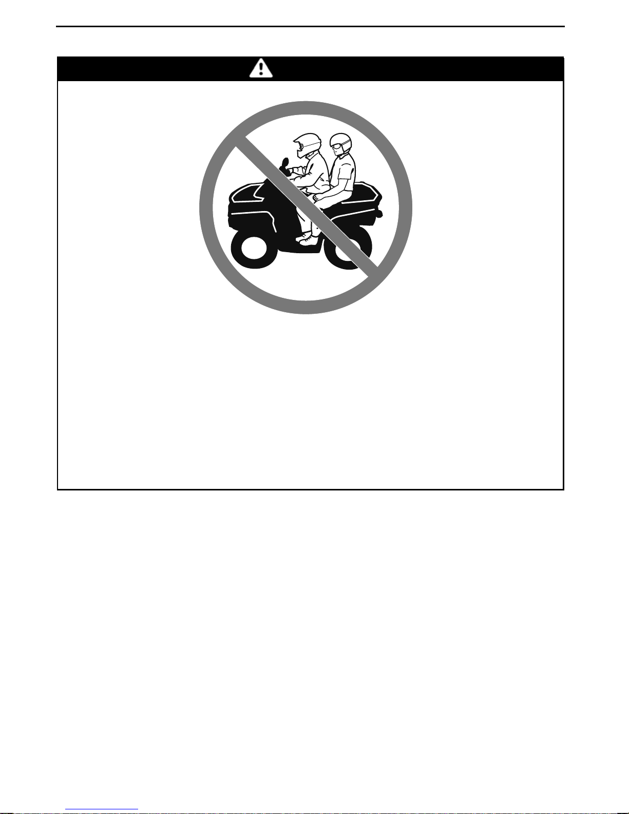
Carrying a passenger on this vehicle.
WHAT CAN HAPPEN
Greatly reduces your ability to balance and control this vehicle.
Could cause an accident, resulting in harm t
HOW TO AVOID THE H AZARD
Never carry passenger. Even with a long seat that provides unrestricted operator movement, it is not designed nor intended to carry passenger(s).
o you and/or your passenger.
14
_______
SAFETY
INFORMATION
________
Page 17
WARNING
OPERATION WARNINGS
POTENTIAL HAZARD
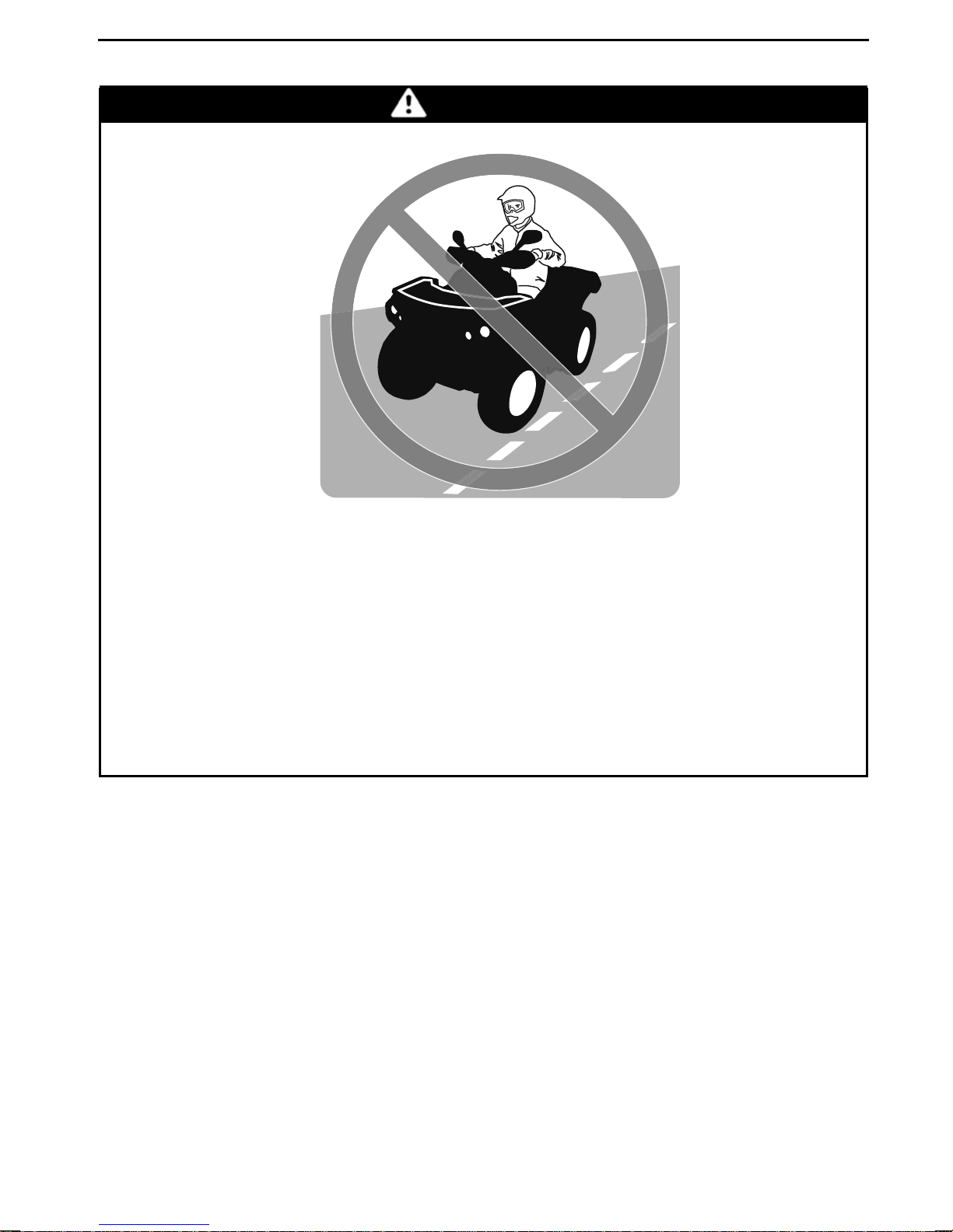
Operating this vehicle on paved surfaces.
WHAT CAN HAPPEN
The tires are designed for off-road use onl
surfaces may seriously affect handling and control of this vehicle, and may
cause the vehicle to go out of control.
HOW TO AVOID THE H AZARD
Never operate this vehicle on any paved surfaces, including sidewalks,
driveways, parking lots and streets.
y, not for use on pavement. Paved
________
SAFETY IN
FORMATION
________
15
Page 18
OPERATION WARNINGS
WARNING
POTENTIAL HAZARD
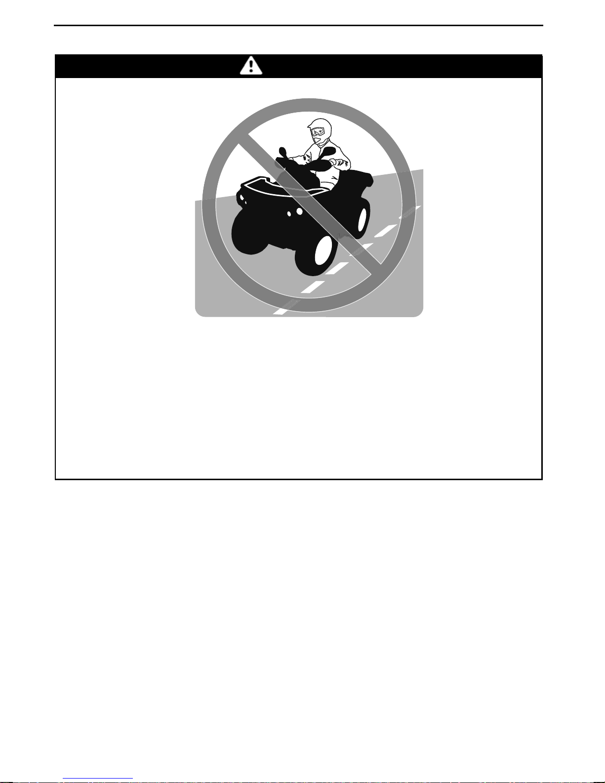
Operating this vehicle on public streets, roads or highways.
WHAT CAN HAPPEN
You can collide with another vehicle.
HOW TO AVOID THE H AZARD
Never operate this vehicle on any public street, road or highway, even a dirt
or gravel one. In many states or provinces i
on public streets, roads or highways.
t is illegal to oper ate this v ehicle
16
_______
SAFETY
INFORMATION
________
Page 19
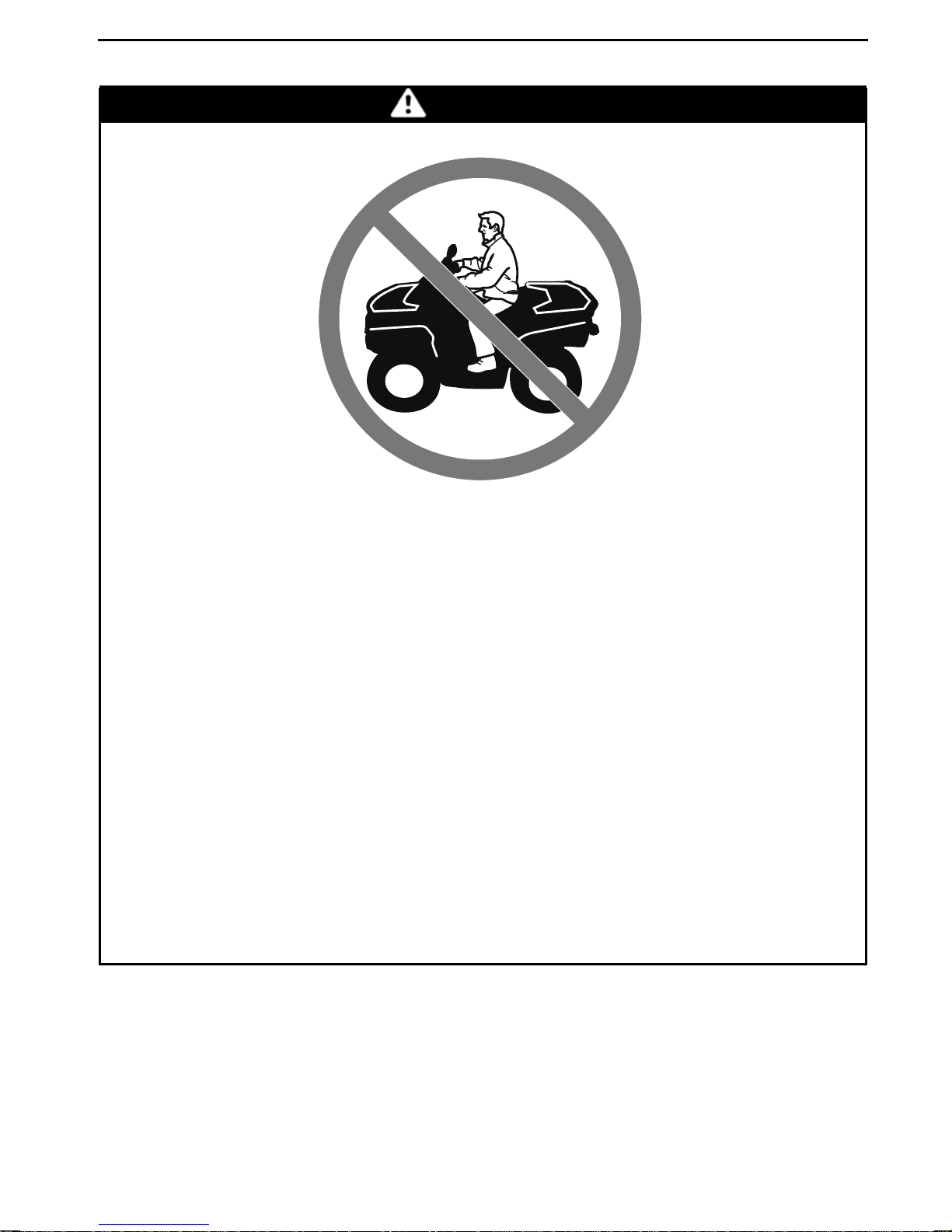
WARNING
OPERATION WARNINGS
POTENTIAL HAZARD
Riding this vehiclewithout wearing an approved h
protective clothing.
WHAT CAN HAPPEN
The following items concern a ll ATV's operator:
– Riding without an approved helmet increases the chances of a severe
head injury or death in the event of an accident.
– Riding without eye protection can result in an accident and increases the
chances of a severe injury in the event of an accident.
– Riding without protective clothing increases the chances of severe injury
in the event of an accident.
HOW TO AVOID THE H AZARD
Always wear an approved helmet that fits properly. You should also wear:
– Eye protection (goggles or visor)
– Gloves and boots
– Long sleeved shirt or jacket
–Longpants.
elmet, eye protectionand
________
SAFETY IN
FORMATION
________
17
Page 20
OPERATION WARNINGS
V00A07Q
WARNING
POTENTIAL HAZARD
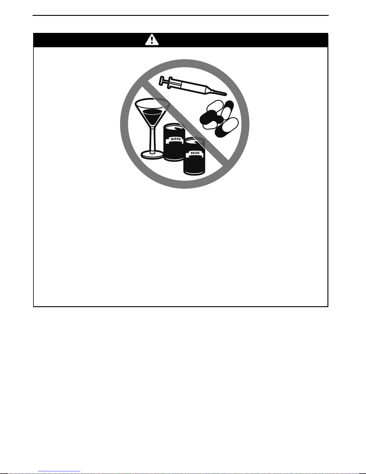
Using this vehicle with drugs or alcohol.
WHAT CAN HAPPEN
Could seriously affect your judgment.
Could cause you to react more slowly.
Could affect your balance and perception.
Could result in an accident or death.
HOW TO AVOID THE H AZARD
Never use this vehicle with drugs or alcohol.
18
_______
SAFETY
INFORMATION
________
Page 21
V00A08Q
OPERATION WARNINGS
WARNING
POTENTIAL HAZARD
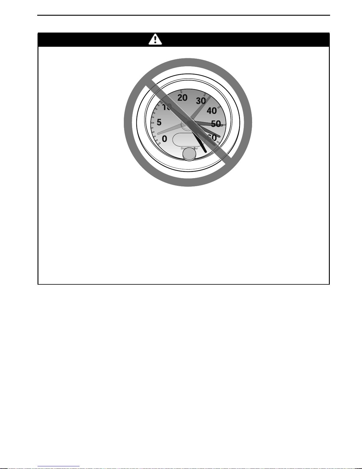
Operating this vehicle at excessive speeds.
WHAT CAN HAPPEN
Increases your chances of losing control of the vehicle, which can result in
an accident.
HOW TO AVOID THE H AZARD
Always travel at a sp eed which is appropriate for the terrain, visibility and
operating conditions, and your experience.
________
SAFETY IN
FORMATION
________
19
Page 22
OPERATION WARNINGS
WARNING
POTENTIAL HAZARD
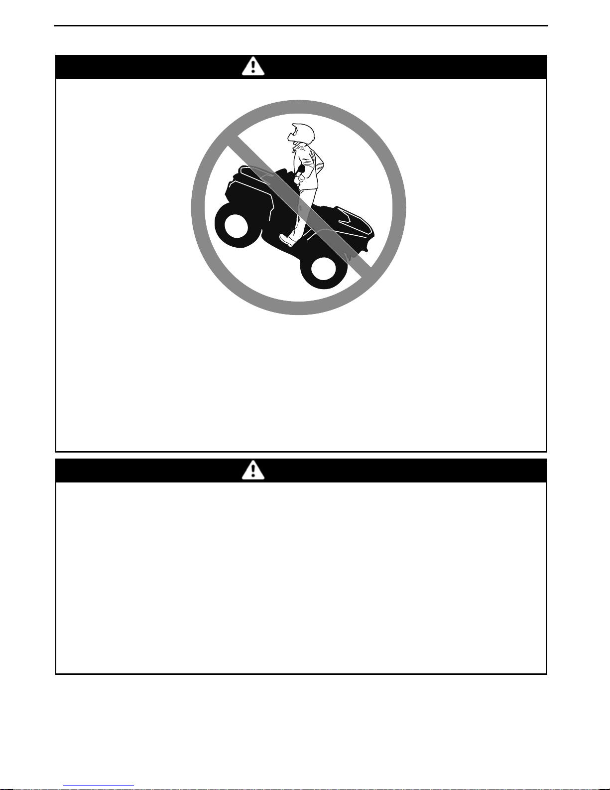
Attempting wheelies, jumps and other stunts.
WHAT CAN HAPPEN
Increases the chance of an accident, including an overturn.
HOW TO AVOID THE H AZARD
Never attempt stunts, such as wheelies or jumps. Do not try to show off.
WARNING
POTENTIAL HAZARD
Failure to inspect the vehicle before operating.
Failure to properly maintain the vehicle.
WHAT CAN HAPPEN
Increases the possibility of an accident or equipment dam age.
HOW TO AVOID THE H AZARD
Always inspect your vehicle prior to every time you use it to make sure the
vehicle is in safe operating condition.
Always follow the inspection and maintenance procedures and schedules
described further in this Operator’s Guide.
20
_______
SAFETY
INFORMATION
________
Page 23
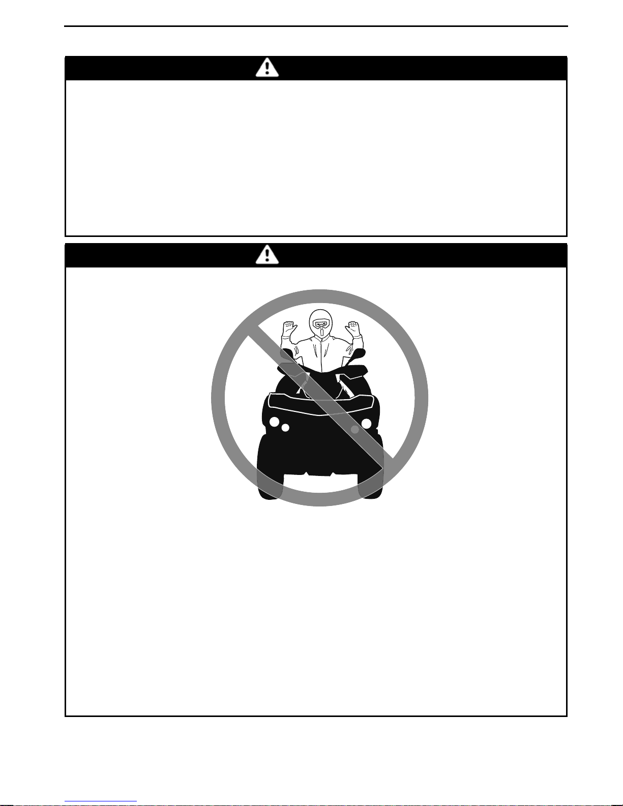
OPERATION WARNINGS
WARNING
POTENTIAL HAZARD
Riding on frozen waterways.
WHAT CAN HAPPEN
Breaking through the ice can lead to severe injury or death.
HOW TO AVOID THE H AZARD
Never ride this vehicle on a frozen surface before you are sure the ice is thick
enough and sound enough to support the vehicle and its load, as well as the
force that is created by a moving vehicle.
WARNING
POTENTIAL HAZARD
Removing hands from handlebar or fe
tion.
WHAT CAN HAPPEN
Removing even one hand or foot can reduce your ability to control the vehicle or could cause you to lose your ba
move a foot from the footrests, your foot or leg may come into contact with
the rear wheels, which could injure you or cause an accident.
HOW TO AVOID THE H AZARD
Always keep both hands on the handlebar and both feet on the footrests
during vehicle operation.
________
SAFETY IN
et from the footrests during opera-
lance and fall off the vehicle. If you re-
FORMATION
________
21
Page 24

OPERATION WARNINGS
POTENTIAL HAZARD
WARNING
Failure to use extra care when operating this vehicle on unfamiliar terrain.
WHAT CAN HAPPEN
You can come upon hidden rocks, bumps, or holes without enough time to
react.
Could result in the vehicle overturning or loss of control.
HOW TO AVOID THE H AZARD
Go slowly and be extra careful when operating on unfamiliar terrain.
Always be alert to changing terrain conditions when operating the vehicle.
22
_______
SAFETY
INFORMATION
________
Page 25
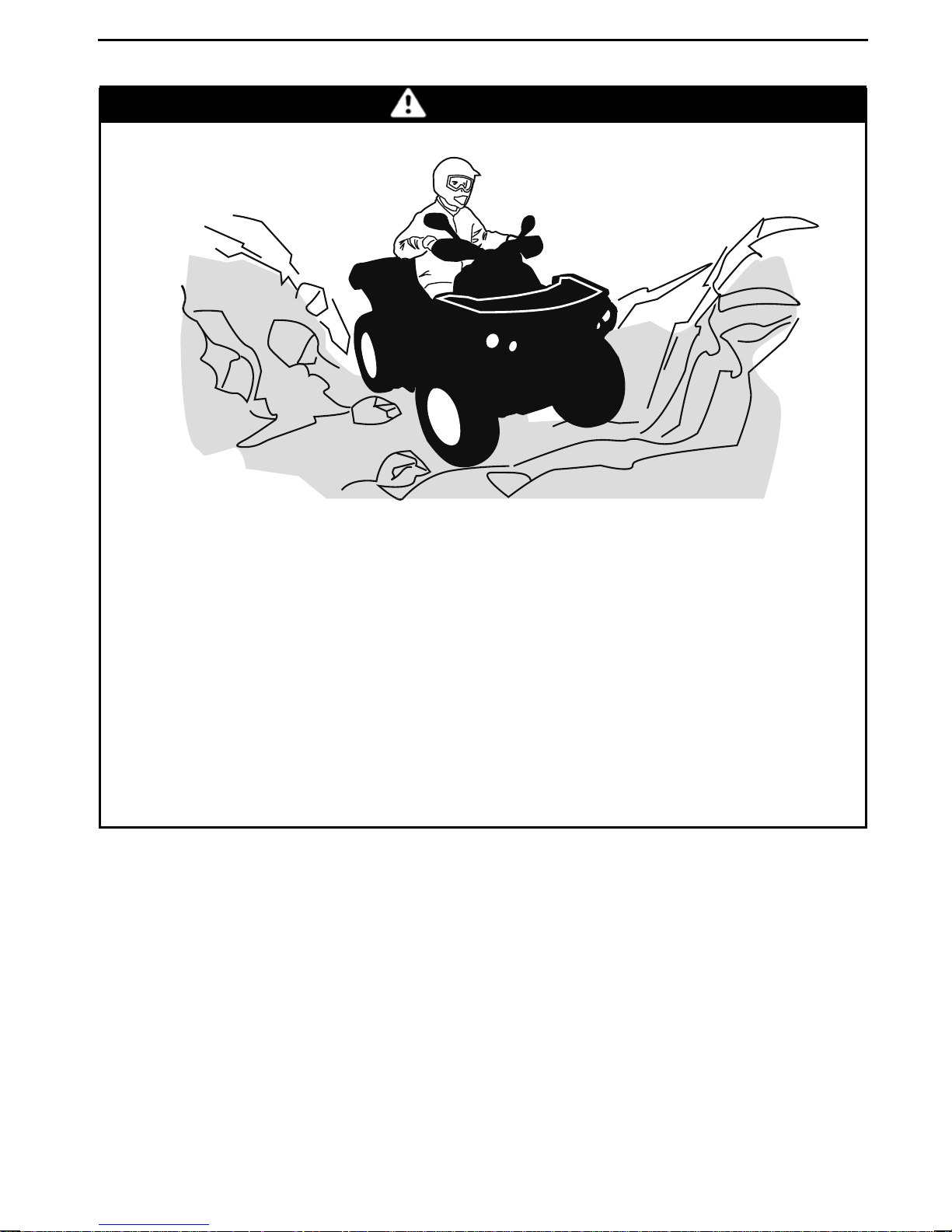
WARNING
OPERATION WARNINGS
POTENTIAL HAZARD
Failure to use extra care when operating on excessively rough, slippery or
loose terrain.
WHAT CAN HAPPEN
Could cause loss of traction or vehicle control, which could result in an accident, including an overturn.
HOW TO AVOID THE H AZARD
Do not operate on excessively rough, slipp
have learned and practiced the skills necessary to control this vehicle on
such terrain.
Always be especially cautious on these kinds of terrain.
ery or loose terrain until you
________
SAFETY IN
FORMATION
________
23
Page 26
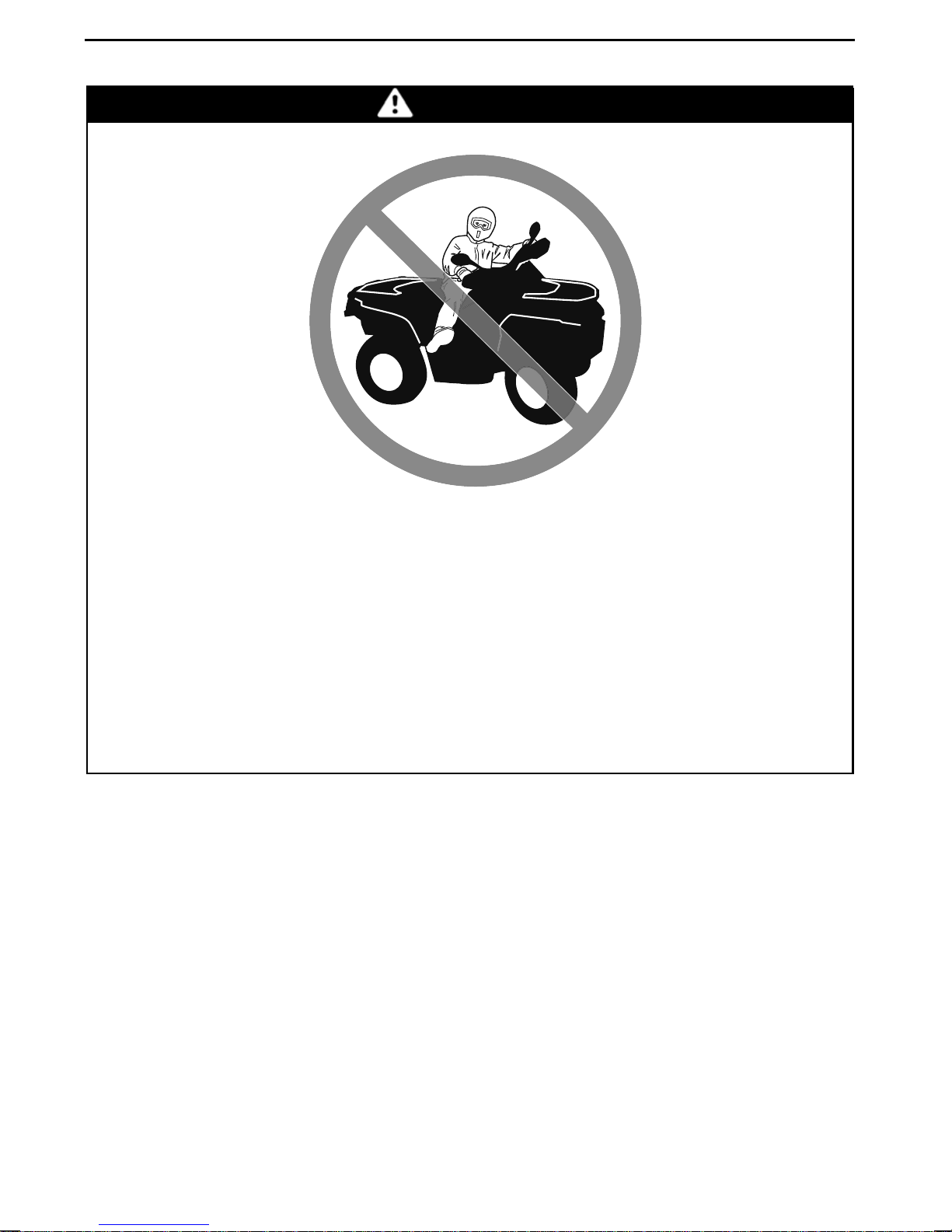
OPERATION WARNINGS
WARNING
POTENTIAL HAZARD
Turning improperly.
WHAT CAN HAPPEN
Vehicle could go out of control, causing a collision or overturn.
HOW TO AVOID THE H AZARD
Always follow proper procedures for turning as described furtherin this Operator’s Guide. Practice turning at low speeds before attempting to turn at
faster speeds.
Do not turn at excessive spe e d.
24
_______
SAFETY
INFORMATION
________
Page 27
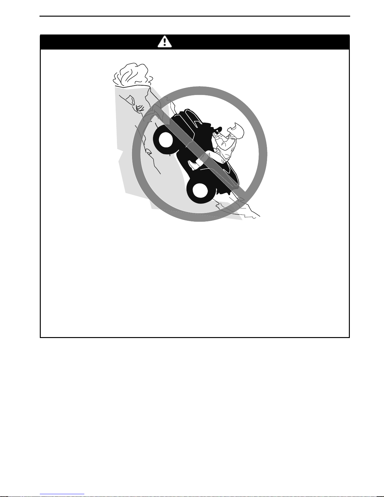
WARNING
OPERATION WARNINGS
POTENTIAL HAZARD
Operating on exces siv ely steep hills.
WHAT CAN HAPPEN
The vehicle can overturn more easily on extremely steep hills than on level
surfaces or small hil ls.
HOW TO AVOID THE H AZARD
Never operate this vehicle on hills too steep for the vehicle or for your abilities.
Practice on smaller hills before attempt in g larger hills.
________
SAFETY IN
FORMATION
________
25
Page 28
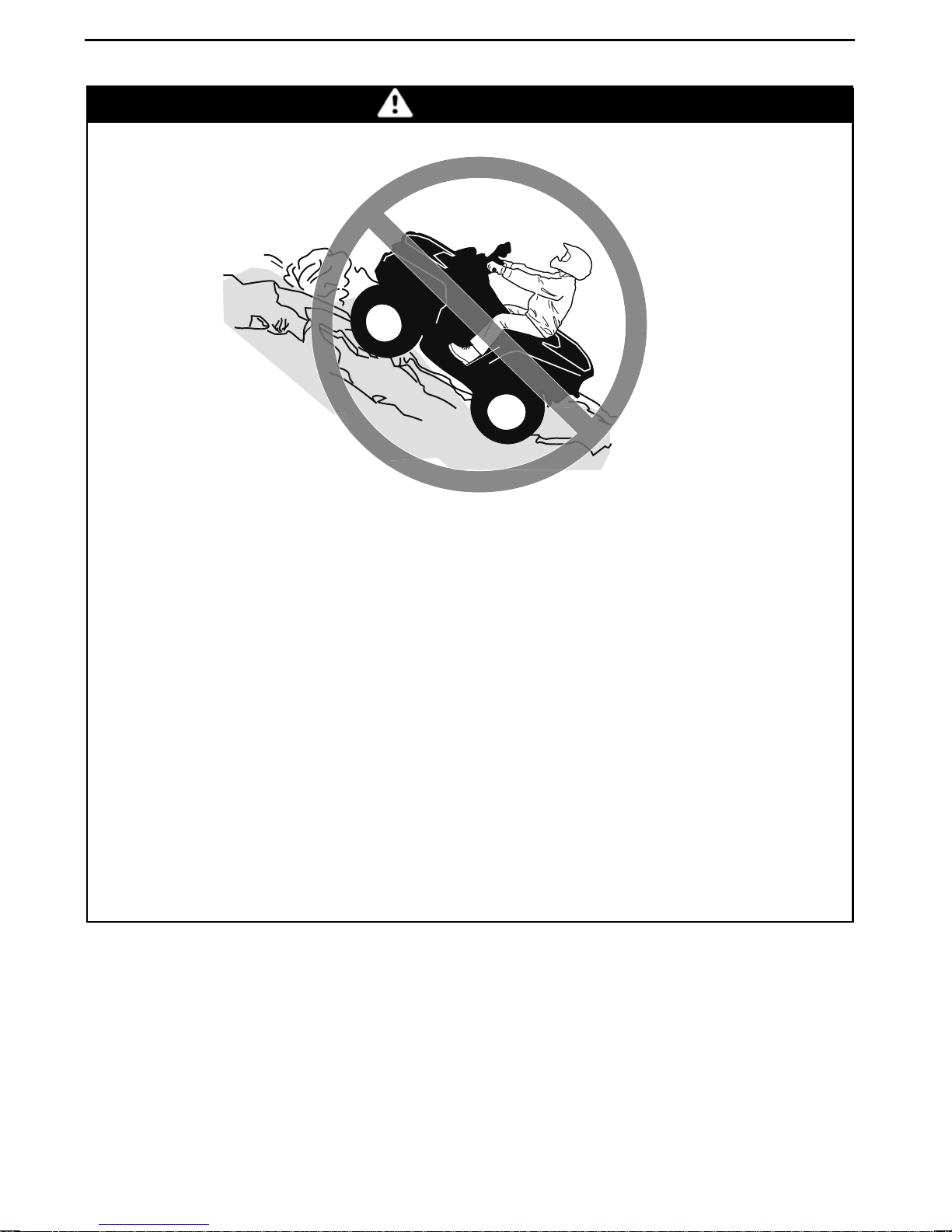
OPERATION WARNINGS
WARNING
POTENTIAL HAZARD
Climbing hills improperly.
WHAT CAN HAPPEN
Could cause loss of control or cause vehicle to overturn.
HOW TO AVOID THE H AZARD
Always follow proper procedures for climbing hills as described further in
this Operator’s Guide.
Always check the terrain carefully before you start up any hill.
Never climb hills with excessively slippery or loose surfaces.
Shift your weight forward.
Never open the throttle suddenly or make sudden gear changes. The vehi-
cle could flip over backwards.
Never go over the top of any hill at high speed. An obstacle, a s harp drop, or
another vehicle or person could be on the o
ther side of the hill.
26
_______
SAFETY
INFORMATION
________
Page 29
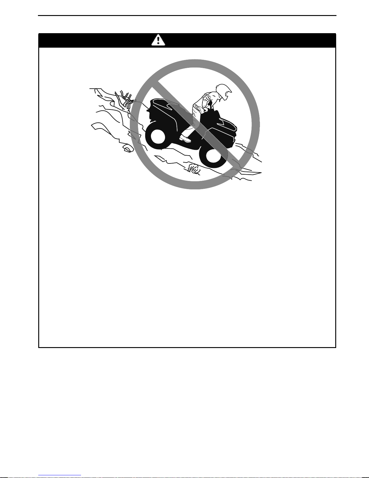
WARNING
OPERATION WARNINGS
POTENTIAL HAZARD
Going down a hill improperly.
WHAT CAN HAPPEN
Could cause loss of control or cause vehicle to overturn.
HOW TO AVOID THE H AZARD
Always follow proper procedures for going do
in this Operator’s Guide.
NOTE: A special technique is required when br
Always check the terrain carefully before you start down any hill.
Shift your weight backward.
Never go down a hill at high speed.
Avoid going down a hill at an angle w hich would cause the vehicle to lean
sharply to one side. Go straight down the hi
wnhillsasdescribedfurther
aking as you go down a hill.
ll where possible.
________
SAFETY IN
FORMATION
________
27
Page 30
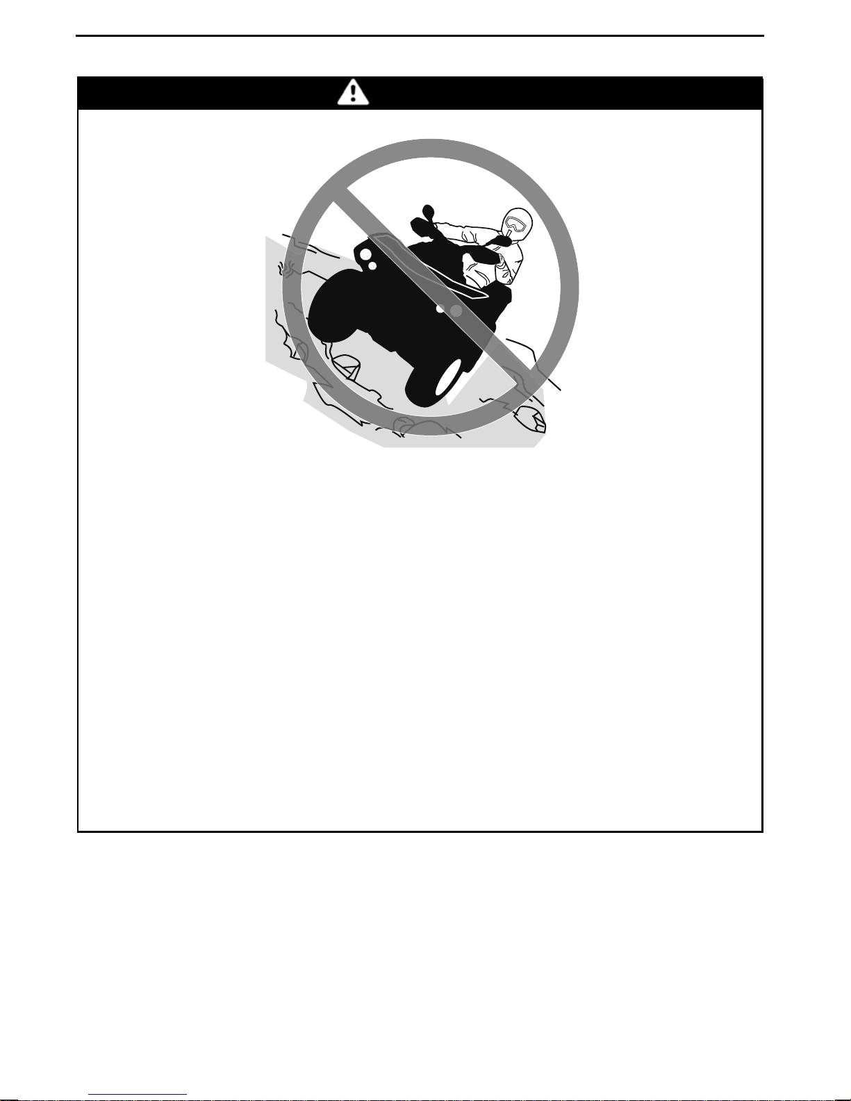
OPERATION WARNINGS
WARNING
POTENTIAL HAZARD
Improperly crossing hills or turning on hills.
WHAT CAN HAPPEN
Could cause loss of control or cause vehicle to overturn.
HOW TO AVOID THE H AZARD
Never attempt toturn the vehicle around on a
the turning technique as described further in this Operator’s G uide on level
ground. Be very careful when turning on any hill.
Avoid crossing the side of a steep hill if possible.
When crossing the s ide of a hill:
Always follow proper procedures as described further in this Operator’s
Guide.
Avoid hills with excessively slippery or loose surfaces.
Shift your weight to the uphill side of the vehicle.
ny hill untilyou have mastered
28
_______
SAFETY
INFORMATION
________
Page 31
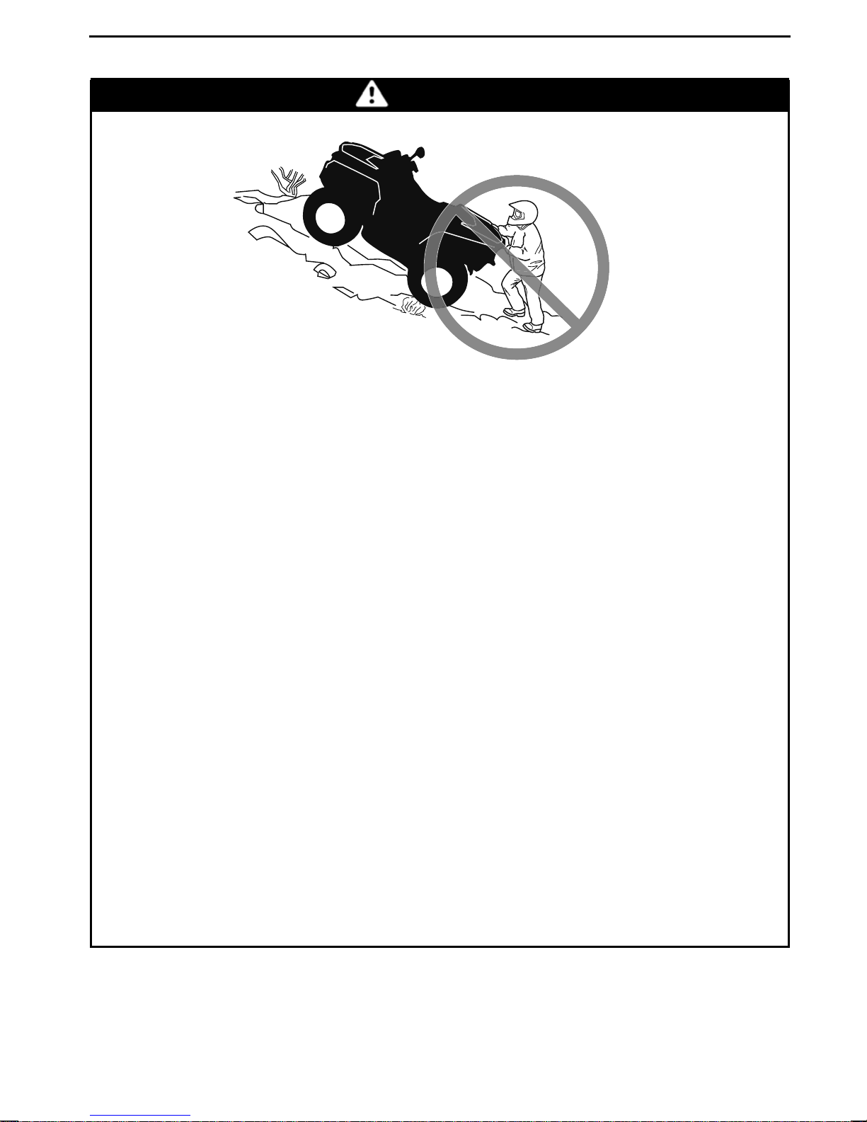
OPERATION WARNINGS
WARNING
POTENTIAL HAZARD
Stalling, rolling backwardsor improperly dismounting while climbing a hill.
WHAT CAN HAPPEN
Could result in vehicle overturning.
HOW TO AVOID THE H AZARD
Use proper gear and maintain steady speed when climbing a hill.
If you lose all forw ard speed:
Keep your weight uphill. Never open the throttle suddenly or make sudden
gear changes. The vehicle could flip over backwards.
Apply the brakes.
Lock parking brake after you have stopped.
Dismount on uphill side, or to a side if pointed straight uphill.
If you begin rolling back wards:
Keep your weight uphill. Never open the throttle suddenly or make sudden
gear changes. The vehicle could flip over backwards.
Never apply the rear brake when rolling backwards.
Apply the front brake gradually.
When fully stopped, apply rear brake as well and lock parking brake.
Dismount on uphill side, or to a side if pointed straight uphill.
Turn the vehicle around and remount, following the procedure described
further in this Operator’s Guide.
________
SAFETY IN
FORMATION
________
29
Page 32
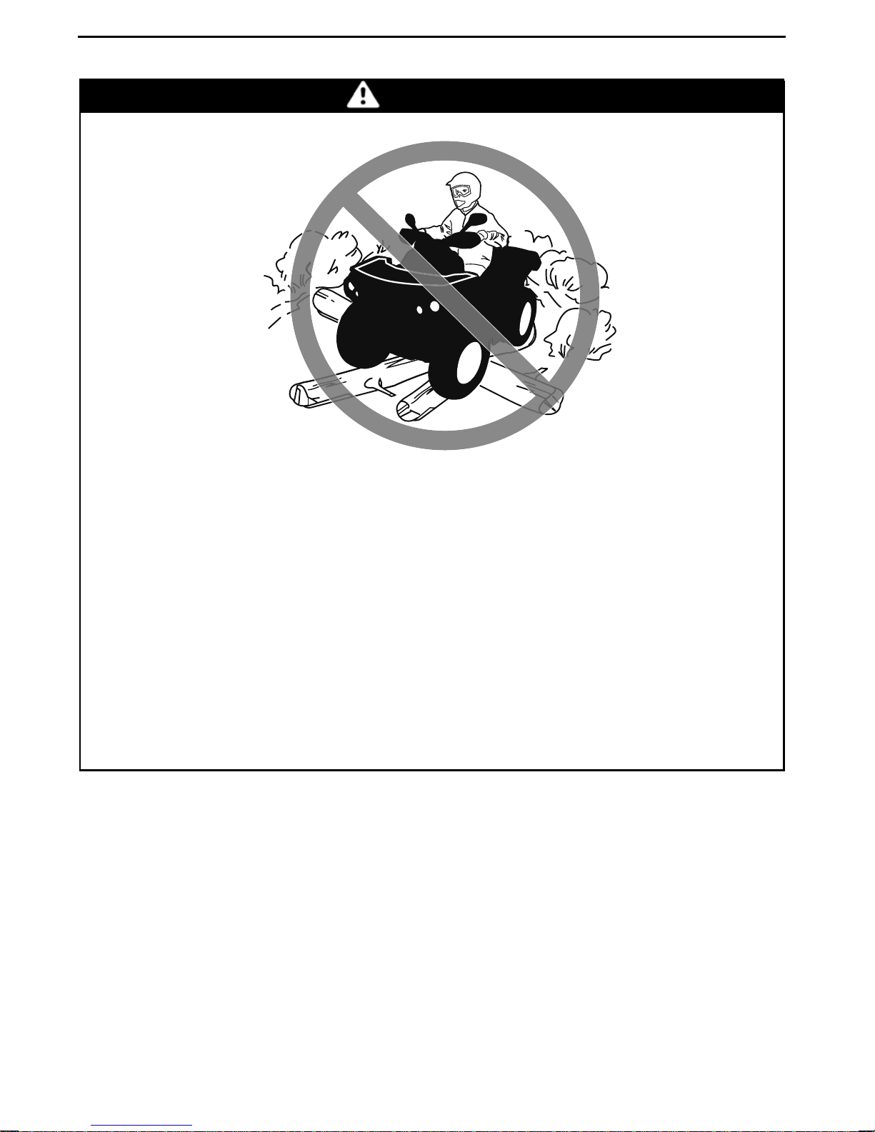
OPERATION WARNINGS
WARNING
POTENTIAL HAZARD
Improperly operating over obstacles.
WHAT CAN HAPPEN
Could cause loss of control or a collision.
Could cause the vehicle to overturn.
HOW TO AVOID THE H AZARD
Before operating in a new area, check for obstacles.
Never attempt to ride over large obstacles, s uch as large rocks or fallen
trees.
When you go over obstacles, always follow proper procedures as described
further in this Operator’s Guide.
30
_______
SAFETY
INFORMATION
________
Page 33
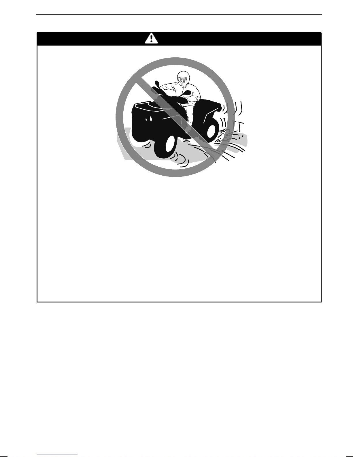
WARNING
OPERATION WARNINGS
POTENTIAL HAZARD
Skidding or sliding improperly.
WHAT CAN HAPPEN
You may lose control of this vehicle.
You may also regain traction unexpectedly,
overturn.
HOW TO AVOID THE H AZARD
Learn to safely control skidding or sliding by practicing at low speeds and
on level smooth terrain.
On extremely slippery surfaces, such as ice, go slowly and be very cautious
in order to reduce the chance of skiddin
which may cause the vehicle to
g or sliding out of control.
________
SAFETY IN
FORMATION
________
31
Page 34
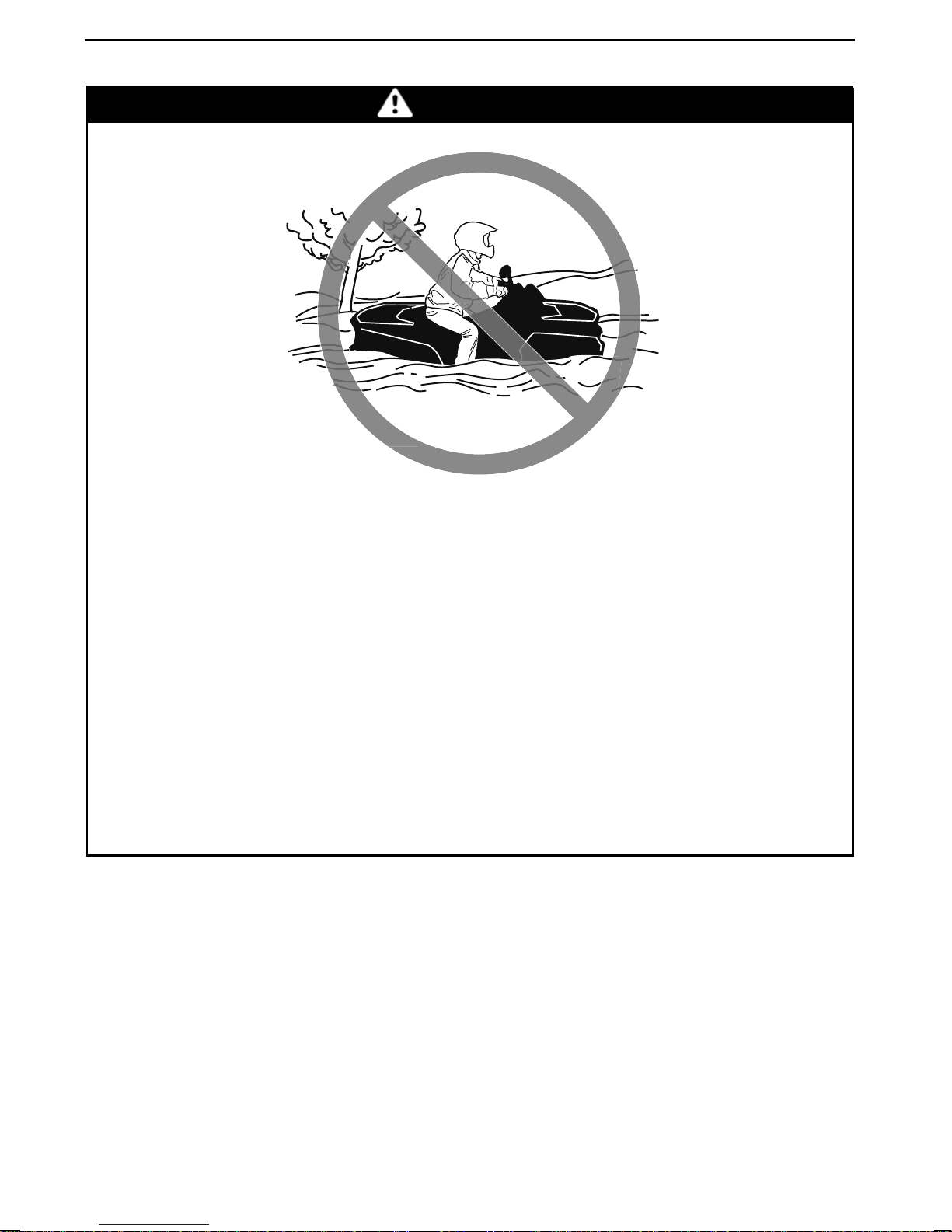
OPERATION WARNINGS
WARNING
POTENTIAL HAZARD
Operating this vehicle through deep or fast flowing water.
WHAT CAN HAPPEN
Tires may float, causing loss of traction and los
to an accident.
HOW TO AVOID THE H AZARD
Never operate this vehicle in fast flowing water or in water deeper than that
specified further in this Oper ator’s Guid
Check water depth and current before you attempt to cross any water. Water should not go above footrests.
Remember that wet brakes may have reduced stopping ability. Test your
brakes after leaving water. If necessa
friction dry out the pads.
e.
ry, apply them several times to let
s of control, which could lead
32
_______
SAFETY
INFORMATION
________
Page 35
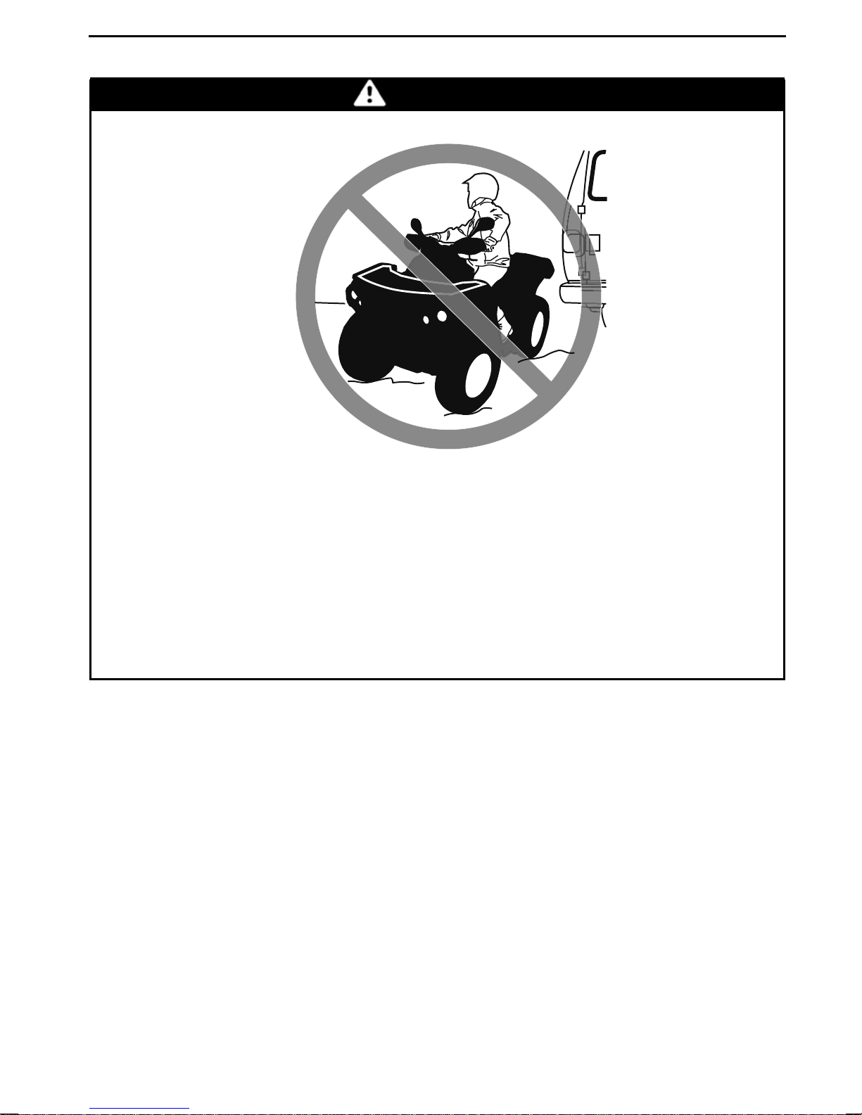
WARNING
OPERATION WARNINGS
POTENTIAL HAZARD
Improperly operating in reverse.
WHAT CAN HAPPEN
Youcouldhitanobstacleorpersonbehindthevehicle,resultinginserious
injury.
HOW TO AVOID THE H AZARD
When you select reverse gear, make sure there are no obstacles or people
behind the vehicle. When it is safe to proceed, go slowly.
________
SAFETY IN
FORMATION
________
33
Page 36
OPERATION WARNINGS
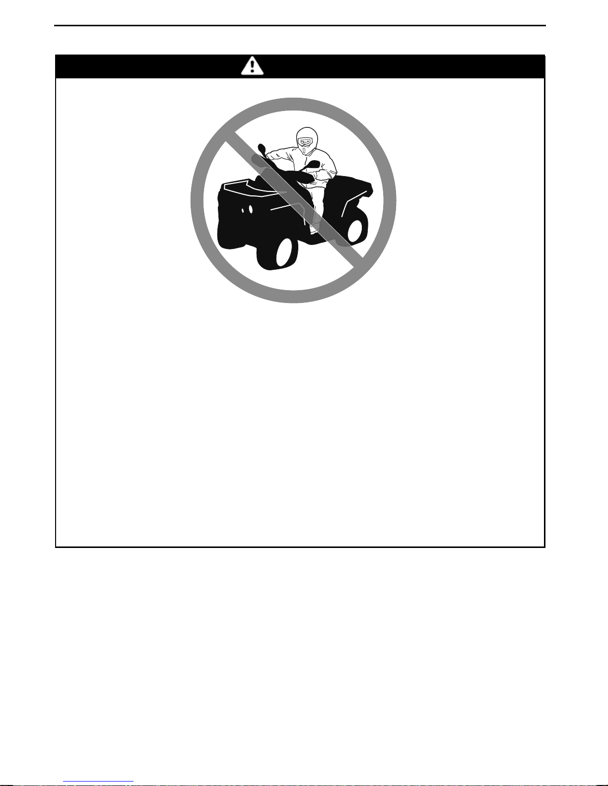
WARNING
POTENTIAL HAZARD
Operating this vehicle with improper tires, or with improper or uneven tire
pressure.
WHAT CAN HAPPEN
Use of improper tires on this vehicle, or operation of this vehicle with
improper or uneven tire pressure, may cause loss of control, tire blow outs,
tire to move around on its rim, and increas
HOW TO AVOID THE H AZARD
Always use the size and type of tires specified further in this Operator’s
Guide for th is vehicle.
Always maintain proper tire pressure as described further in this Operator’s
Guide.
Always replace wheels or tires that are damage d.
es the risk of an accident.
34
_______
SAFETY
INFORMATION
________
Page 37
WARNING
OPERATION WARNINGS
POTENTIAL HAZARD
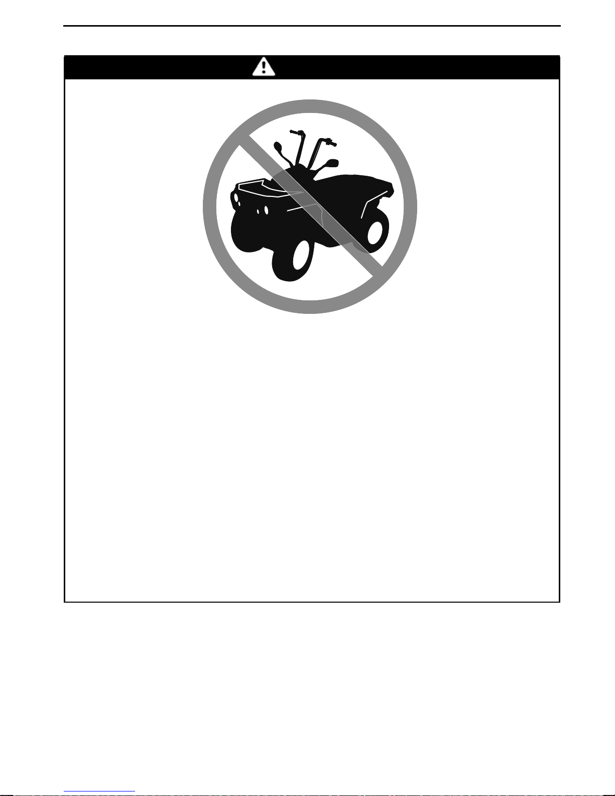
Operating this vehicle with improper modifications.
WHAT CAN HAPPEN
Improper installation of accessories or modification of this vehicle may
cause changes in handling which in some situations could lead to an accident.
HOW TO AVOID THE H AZARD
Never modify this vehicle through improper installation or use of accessories. All parts and accessories added to this vehicle should be approved
by BRP and should be installed and used acc
have questions, consult an authorized Can-Am dealer.
NEVER install passenger seat or use t
Modification of the vehicle to increase speed and performance may violate
the terms and conditions of your vehi
tain modifications including the removal of engine or exhaust components
are illegal under most laws.
he racks to carry a passenger.
cle's limited warranty. In addition, cer-
ording to instructions. If you
________
SAFETY IN
FORMATION
________
35
Page 38
OPERATION WARNINGS
WARNING
POTENTIAL HAZARD
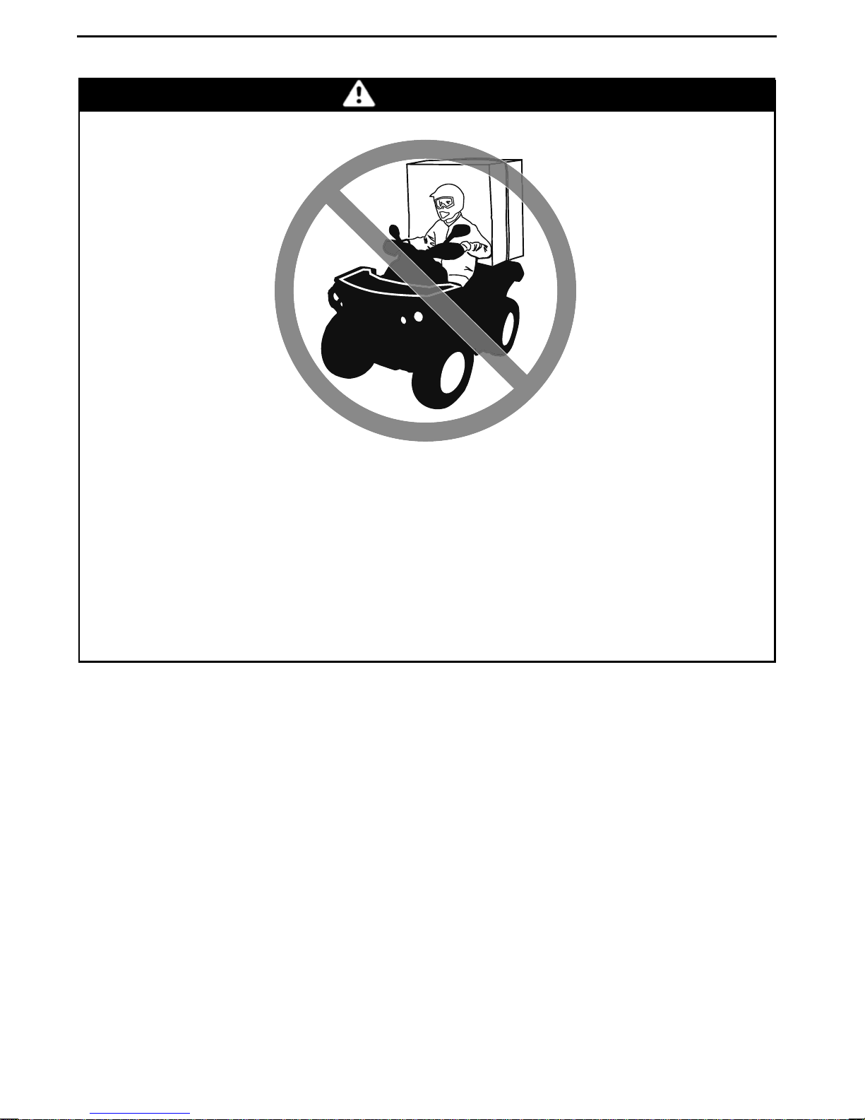
Overloading this vehicle, carrying or towing cargo improperly.
WHAT CAN HAPPEN
Could cause changes in vehicle handling which could lead to a n accident.
HOW TO AVOID THE H AZARD
Never load cargo on this veh icle.
Never tow cargo or another vehicle with this vehicle.
36
_______
SAFETY
INFORMATION
________
Page 39
V03M01Q
POTENTIAL HAZARD
OPERATION WARNINGS
WARNING
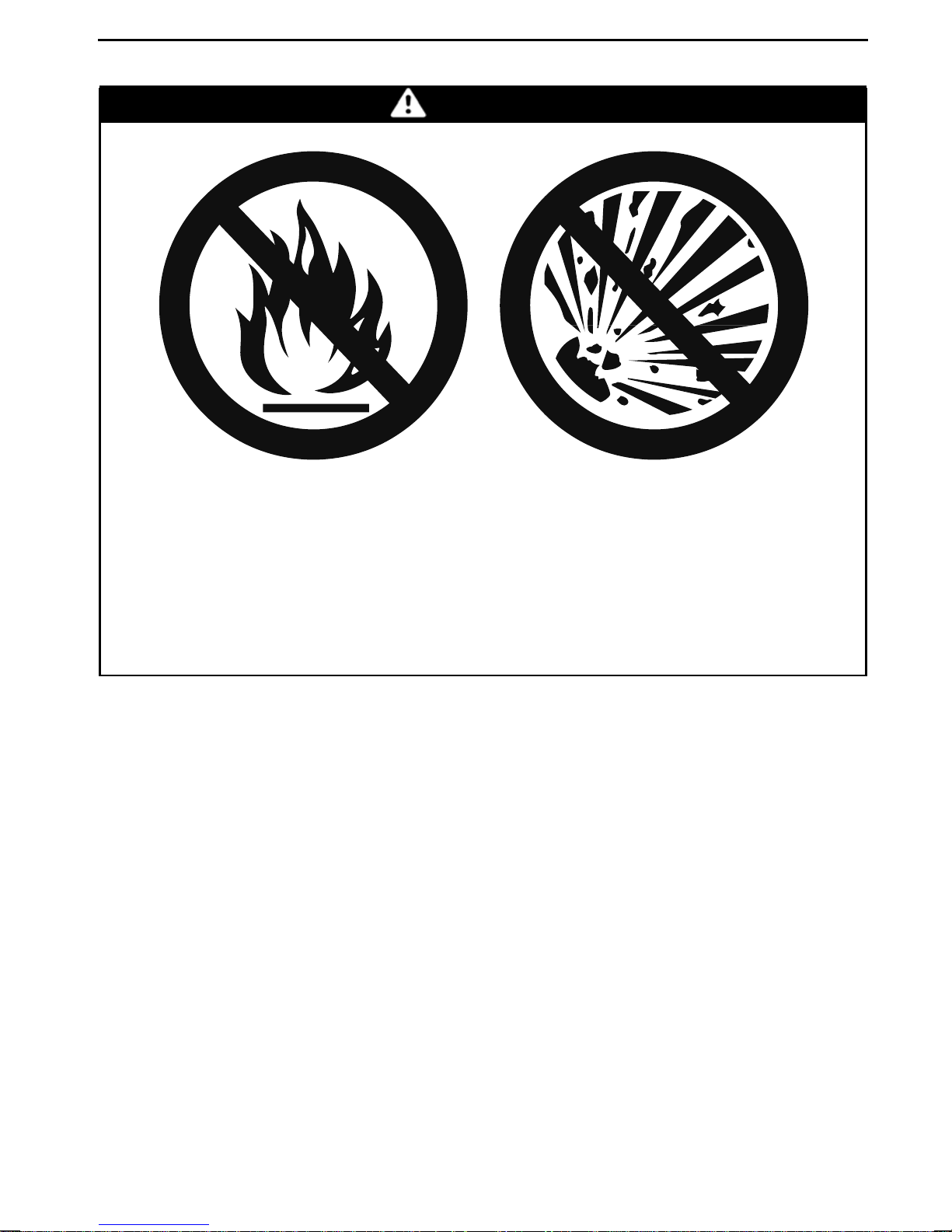
Transporting flammable or dangerous material can lead to explosions.
WHAT CAN HAPPEN
This can cause serious injury or death.
HOW TO AVOID THE H AZARD
Never transport flammable or dangerous material.
________
SAFETY IN
FORMATION
________
37
Page 40

RIDING THE VEHICLE
To fully appreciate the pleasures and excitement of riding this vehicle, there are
some basic rules and tips that you MUST follow. Some may be new to you while
others may be common sense or obvious.
Please take the time to study this Operator's Guide and all on-product safety
labels as well as the
completely describe what you should know about this vehicle before riding it.
For thechild'ssafety,we strongly recommend youalsofollow and enforcethisrecommendation. You are the sole judge of a rider's capability to unde rstand the risks
and operate a vehicle safely.
Individuals with cognitive or physical impairments or who a re high risk takers have
an increased exposure to overturns or collisions which may result in injury including death.
Not all vehicles are the same. Each has its own unique performance characteristics, controls and features. Each will ride and h andle differently.
Become completely familiar with the operational con tro ls and the general operation of the vehicle before venturing into off road conditions. Practice driving in a
suitable area free of hazards and feel the response of each control. Drive at low
speeds. Higher speeds require greater experience, knowledge and suitable riding
conditions.
SAFETY DVD
video that came with this vehicle. They more
Riding conditions vary from place to place. Each is subject to weather conditions
which may radically change from time to time and from season to season.
Riding on sand is different than riding on snow or through forests or marshes.
Each location may require a greater degree of awareness and skills. Show good
judgement. Always proceed with caution. Please do not take any unnecessary
risks that could leave you stranded or possibly injured.
Never assume that the vehicle will go everywhere safely. Sudden changes in terrain caused by holes, depressions, banks, softer or harder “ground“ or other irregularities may cause the vehicle to topple or become unstable. To avoid this, slow
down and always observe the terrain ahead. If the vehicle does begin to topple or
tip over, the best advice is to immediately get off... AWAY from the direction of the
tip over!
Pre-Ride Inspection
WARNING
Perform a pre-ride inspection before each ride to detect any potential problem that could occur during operat
monitor wear anddeterioration before they become a problem. Correct any
problem that you discover to reduce the risk of a breakdown or crash. See
an authorized Can-Am dealer if n
ion. The pre-ride inspection can help you
ecessary.
Before using this vehicle, the operator and/or an adult should always perform the
following pre-ride inspectio
38
_______
n check list.
SAFETY
INFORMATION
________
Page 41
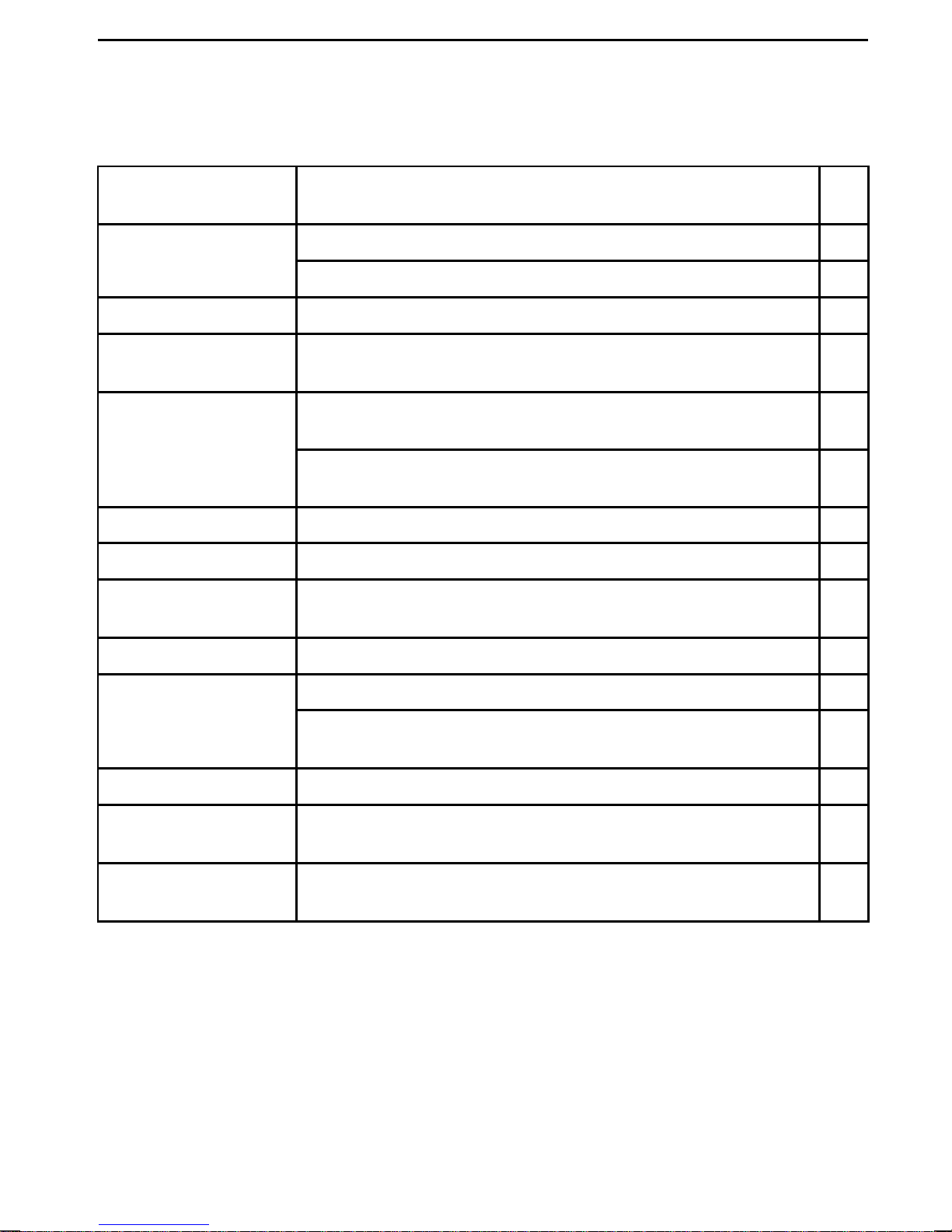
Pre-Ride Inspection Check List
What to Do Before Starting the Engine (Key OFF)
RIDING THE VEHICLE
ITEMS TO BE
INSPECTED
Check fuel and engine oil.
Fluids
Check brake system for fluid leaks (DS 90 X).
Leaks
Steering
Throttle lever
Parking brake Apply parking brake and ensure it operates properly.
Tires
Wheels
Check for any l eaks un der vehicle.
Check if steering operates freely by completely turning it
from side to side.
Activate throttle lever several times to ensure it operates
freely. It must return to idle position when released.
Ensure the speed limiter screw is properly adjusted
according to rider capability.
Check tire pressure and condition.
Check wheels for damage and for abnormal play, and
check lug nuts are tightened.
INSPECTION TO PERFORM
✔
Radiator
Drive chain and
sprockets
Seat
Service a nd storage
compartments
Chassis and
suspension
Check cleanliness of the radiator.
Inspect sprockets for wear or damages.
Check drive chain, slider and drive chain tensioner for
proper adjustment and lubrication (as applicable).
Ensure operator seat is properly installed and latched.
Check if service and storage compartmen ts are properly
latched.
Check underneath vehicle for any debris on chassis or
suspension, properly clean chassis and suspension.
________
SAFETY IN
FORMATION
________
39
Page 42

RIDING THE VEHICLE
What to Do Before Starting the Engine (Key ON)
ITEMS TO BE
INSPECTED
Indicator lamps
Lights
Engine
Check operation of engi ne oil/temperature indicator lamp
(during first few seconds of key ON).
Ensure the N (neutral) and R (reverse) indicator lamps
come ON as applicable to transmission lever selection.
Check operation and cleanliness of headlights and taillight.
Check operation of high and low beam.
Check operation of brake light.
Ensure fuel valve is selected to the ON position.
INSPECTION TO PERFORM
What to Do After the Engine is Started
ITEMS TO BE
INSPECTED
Indicator lamps
Ensure engine oil/temperature indicator lamp is off (shut
engine off if light remains on).
INSPECTION TO PERFORM
✔
✔
Transmission lever
Brakes
Emergency engine
stop switch
Ignition switch
Check operation of transmission lever (F, N, and R).
Drive forward slowly a few feet and apply both brake levers
and the brake pedal individually. The brakes must fully
apply. Lever an d pedal must fully return when released.
Check that the emergency engine stop switch is working
properly.
Check if ignition switch is working properly by restarting
and stopping the engine.
40
_______
SAFETY
INFORMATION
________
Page 43
RIDING THE VEHICLE
Clothing
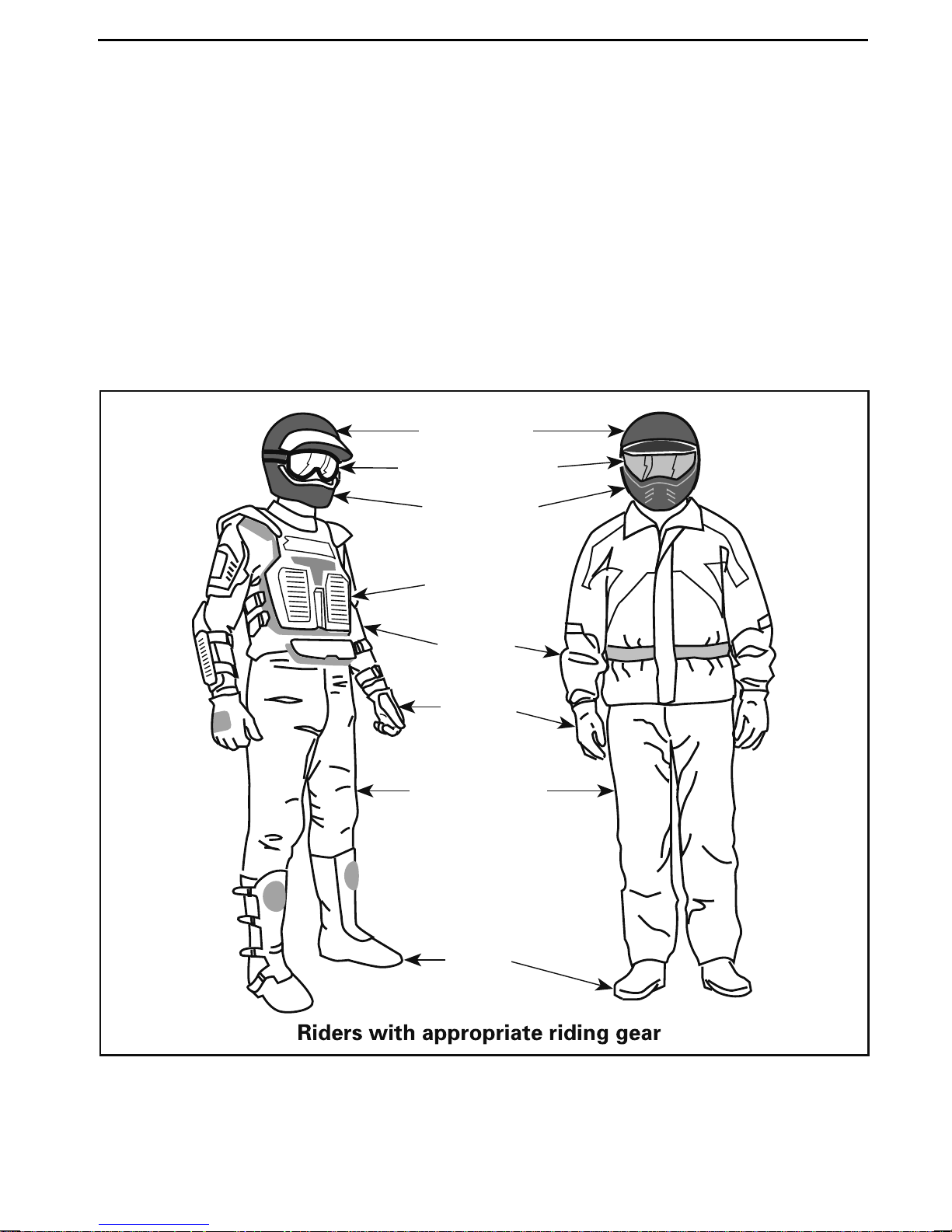
Actual weather conditions should help you decide how to dress. Always dress
for the coldest weather expected. Thermal underwear next to the skin provides
good insulation. It is important that the operator always wears the appropriate
protective clothing and apparel, including an approved helmet, eye protection
boots, gloves, a long sleeved shirt and pants. This type of clothing will provide
you protection from some of the minor hazards you may encounter en route. The
operator must never wear loose clothing such a s a scarf that may get entangled
the vehicle or on tree branches and shrubs. Dependingonconditions,anti-fogging
goggles or sun glasses may be required. Sun glasses should only be worn during
the daytime. D ifferent colored lenses available for goggles o
distinguish terrain variatio ns.
Approved
helmet
Eye protection
r glasses help you
in
,
Rigid chin
guard
Chest
protector
Long
sleeves
Gloves
Long, sturdy
pants
V00A0RN
________
SAFETY IN
Boots
FORMATION
________
41
Page 44

RIDING THE VEHICLE
Carrying a Passenger
This vehicle is designed specifically to carry an operator only. Even with a long
seat, this vehicle is not designed nor intended to carry passenger(s). Carrying
passenger(s) may affect the stability and y ou r contro l of the vehicle.
Carrying Loads
Never load cargo on this vehicle.
Recreational Riding
Respect the rights and limitations of others. Stay away from areas designated
for other types of off road use. This includes snowmobile trails, equest
cross country ski trails, m ountain bike trails etc. Never assume there are no other
usersonthetrail. Alwaysstaytothecompleterightofthetrailanddonotzigzag
toonesideofthetrailthentheother. Bepreparedtostoporpullofft
another trail user appears in front of you.
rian trails,
o the side if
Always keep a safe distance from other riders. Your judgment
rain conditions, weather, mechanical condition of your vehicle and the "trust in
judgment" you have in others around y ou will help you make a better choice of
appropriate safe distance. This vehicle, like any other
stop "on a dime".
Beforeyouride,tellsomeonewhereyouareplanningtotr
time of re turn.
Depending on the length of your ride, carry additio
and emergency equipment. Find out where you can get additional gasoline and
oil. Be prepared for the possible conditions you may encounter.
Adjustable wrench Mobile phone
Colored lens goggles
Flashlight
First aid kit
Friction tape Trail map
Knife
Provided tool kit
Snack
Spare light bulbs
motorized vehicle, cannot
avel and your expected
nal tools, drinking water, food
of speed, ter-
Environment
One of the benefits of this vehicle is that it can take you off the beaten path away
from most communities. However
rights of others to enjoy it. Do not ride in environmentally sensitive areas. Do not
drive over forest crops or shrubs... nor cut down trees or take down fencing... nor
spin your wheels and destroy t
42
_______
, you should always respect nature and the
he terrain. “Tread Lightly”.
SAFETY
INFORMATION
________
Page 45

RIDING THE VEHICLE
This vehicle can cause OHV wildfires if debris builds up near the exhaust o r other
engine hot spots and ignites then falls off into dry grass. Avoid riding in wet areas,
through muskeg or tall grass, where debris can build up. Should you ride in those
areas, inspect and remove all debris from your engine and hot spots.
Chasing wildlife is in man y areas ille ga l. Wildlife can die o f exhaustion after b
chased by a motorized vehicle. If you encounter animals on the trail, stop and observe quietly and with caution. It will be one of the better memories of your life.
Observe the rule... “what you take in, carry out”. D o not litter. Do not start campfires unless you have permission to do so... and then only... away from dry areas.
The hazards you may create on the trailmaycauseinjurytoothersor
at a later date.
Respect farm lands. Always obtain the permission of the landowner
on private land. Respect crops, farm animals and property lines. If you come to a
closed gate, close it again behind you.
Finally, do not pollute streams, lakes or rivers and do not modify the engine or exhaust system, or remove any of its components.
yourself,even
before riding
eing
Design Limitation
Although the vehicle is exceptionally rugg ed for its class, it is still a light vehicle by
definition and its operation must be restricted to its p
The add itio n of weight to any p art of the vehicle changes its gravitational stability
and modifies its performance.
roper purpose.
Off-Road Operation
The very nature of off-road operation is dangerous
been specially prepared to carry vehicles, presents an inherent danger where
angularity, terrain substance and exact steepness are unpredictable. The terrain
itself presents a continual element of danger, w
by anyone venturing over it.
An operatorwhotakesa vehicle off-road sho
selecting the safest path and keeping close watch on the terrain ahead of him. On
no account should the vehicle be operated by anyone who is not completely familiar with the driving instructions applic
on steep or treacherous terrain.
able to the vehicle, nor should it be operated
uld always exercise the utmost care in
. Any terrain, which has not
hich must be knowingly accepted
General Operating and Safety Precautions
Care, caution, experience and driving skill are the best precautions against the hazards of vehicle operation.
Whenever there is the slightest doubt that the vehicle can safely negotiate an obstacle or a particular piece of terrain, a lways choose an alternate route.
In off-road operation, power and traction, not speed, are important. Never drive
faster than visibility and your own ability to select a safe route p erm it.
________
SAFETY IN
FORMATION
________
43
Page 46

RIDING THE VEHICLE
Constantly watch the terrain ahead for sudden changes in slopes or obstacles,
such as rocks or stumps, that may cause loss of stab ility, resulting in tip-over or
rollover.
Never operate the vehicle if the controls do not function normally.
When operating in reverse, check that the path behind the vehicle is free of people
or obstacles. Proceed slowly and avoid sharp turns.
BRP recommends that you remain seated on your ATV when operating in reverse.
Avoid standing up. Your weight could shift forward against the throttle lever causing an unexpected acceleration and loss of c ontrol.
When stopped or parked, always apply the parking brake. This is especially important when parking on a slope. On very steep inclines or if the vehicle is
cargo, the wheels should be blocked using rocks or bricks. Remember to turn the
fuel valve to the closed p osition.
Uphill Driving
carrying
Due to configuration, this vehicle has excellent climbing a
it is possible to tip over before traction is lost. For example, its common to encounter terrain situations where the top of the hill has eroded to a point that the
hill peak rises very sharply. The vehicle can readily neg
however, in doing so, when the front of the vehicle is driven to a point that the
vehicle's balance moves rearward, a tip over can occur.
The same situation may apply if an embedded object causes the front of the vehicle to climb more than desired. If such a situation occurs take an alternate route.
Be aware of side hilling dangers wh en d oing so.
It is also wise to know the terrain condition on the other side of the hill or bank. All
too often there exists a sharp drop-off that is im
Downhill Driving
This vehicle can climb slopes that are steeper than it can safely descend. Therefore, it is essential to ensure that a safe route exists to descend a slope before you
climb it.
Deceleratingwhilenegotiatinga slippery downhillslopecould"toboggan"thevehicle. Maintain steady spee d and/o r acceler
Side Hilling
ate slightly to regain control.
possible to negotiate or descend.
bility, so much so that
otiate such a condition
Whenever possible, such operation should be avoided. If necessary, do so with
extreme caution. Side hilling on steep inclines could r esult in rollover. In addition,
slippery or loose surfaces could resul
tempt to turn the vehicle downhill with the slide. Av oid all objects or depressions
that will intensify the raising of one side of the vehicle higher than the other, thus
causing rollover.
44
_______
SAFETY
t in uncontrollable side sliding. Do not at-
INFORMATION
________
Page 47

RIDING THE VEHICLE
Drop-Offs
This vehicle will“bottom-out“andusuallystopifeitherthe front or rear wheels are
driven over a drop-off. If the drop is sharp or deep, the vehicle will nose dive and tip
over.
WARNING
Avoid negotiating drop-offs. Reverse and select an alternate route.
Riding on Snow Covered Surfaces
When performing the pre-ride inspectio n, pay specia l attention to locations on the
vehicle where snow and/or ice accumulations may obstruct visibility of the lights
and reflectors, clog ventilation openings, or interfere with the movement of the
control levers and switches. Before starting w ith your ATV check the steering,
throttle and brake lever and pedal controls for interference free operation.
Whenever an ATV is ridden on a snow covered drive path the tire grip is generally
reduced causing the vehicle to react differently to control inputs from the operator.
On low grip surfaces, the steering responses are not as crisp an d precise, stopping
distances are lengthened and acceleration bec omes sluggis h. Slow dow n and do
not "gun" the throttle. This will only result in spinning of the tires and possibly in an
over steering slide of the vehicle. Avoid hard braking. This will possibly result in a
straight line slide of the vehicle. Again, the best advice is to safely reduce speed in
anticipation of a maneuver so to give yourself time and distance to regain total vehicle control before it spins out of your control.
As you drive your ATV over a loose snow c overed surface, snow dust will be
picked up in the wake turbulence of the moving vehicle and transported to co n tact
and accumulate or melt on some exposed components including rotating parts
like brake discs. Water, snow or ice may affect the response time of the brake
system of your ATV. Even when not required to reduce vehicle speed apply brakes
frequently to prevent ice or snow accumulation and to dry brake pads and discs.
While doing so in low risk driving situations you will test for grip level and keep
yourself alerted to how the vehicle reacts to your control inputs. Always keep
footboards, brake and throttle levers free of snow and ice. Frequently wipe snow
off seat, hand grips, lights a nd reflectors.
The depth of the snow cover may hide rocks, tree stumps or other objects, and if
it is wet, may totally impede the drivability as the vehicle becomes bogged do wn
or completelyloosestractionin slushy snow. Look far ahead and always be watchful of any visible clues that mightindicatethepresenceof such obstacles. In doubt
steer clear. Avoid driving on any frozen body of water before checking that the ice
will safely support the ATV, its riders and its load of cargo. Remember that a given
thickness of ice may be sufficient to support a snowmobile, but not an ATV of an
identicalweightbecauseofthesmallerload bearing surface of the four tire contact
patches as compared to that of a snowmobile track and skis.
To maximize comfort and avoid frostbite, always wear clothing and ATV protective
equipment appropriate for the weather conditions you will be exposed to during
your ride.
________
SAFETY IN
FORMATION
________
45
Page 48
RIDING THE VEHICLE
At the end of each ride it is a good practice to cle an the vehicle body and all moving
components (brakes, steering components, drive lines, controls, etc.) from any
snow or ice accumulations. Wet snow will turn to ice during the shut down period
and become more difficult to remove at the next pre-ride inspection.
Riding Techniques
Riding your vehicle too fast for your skills or the conditio ns may result in injury. Apply only enough throttle to proceed safely. Statistics show that high speed turns
usually re su lt in mishaps and injury. Always remember that this ve h
Its pure weight alone may entrap you should it fall and pin you down. Always use
proper riding techniques to avoid vehicle overtu rn s on hills and rough terrain and in
turns.
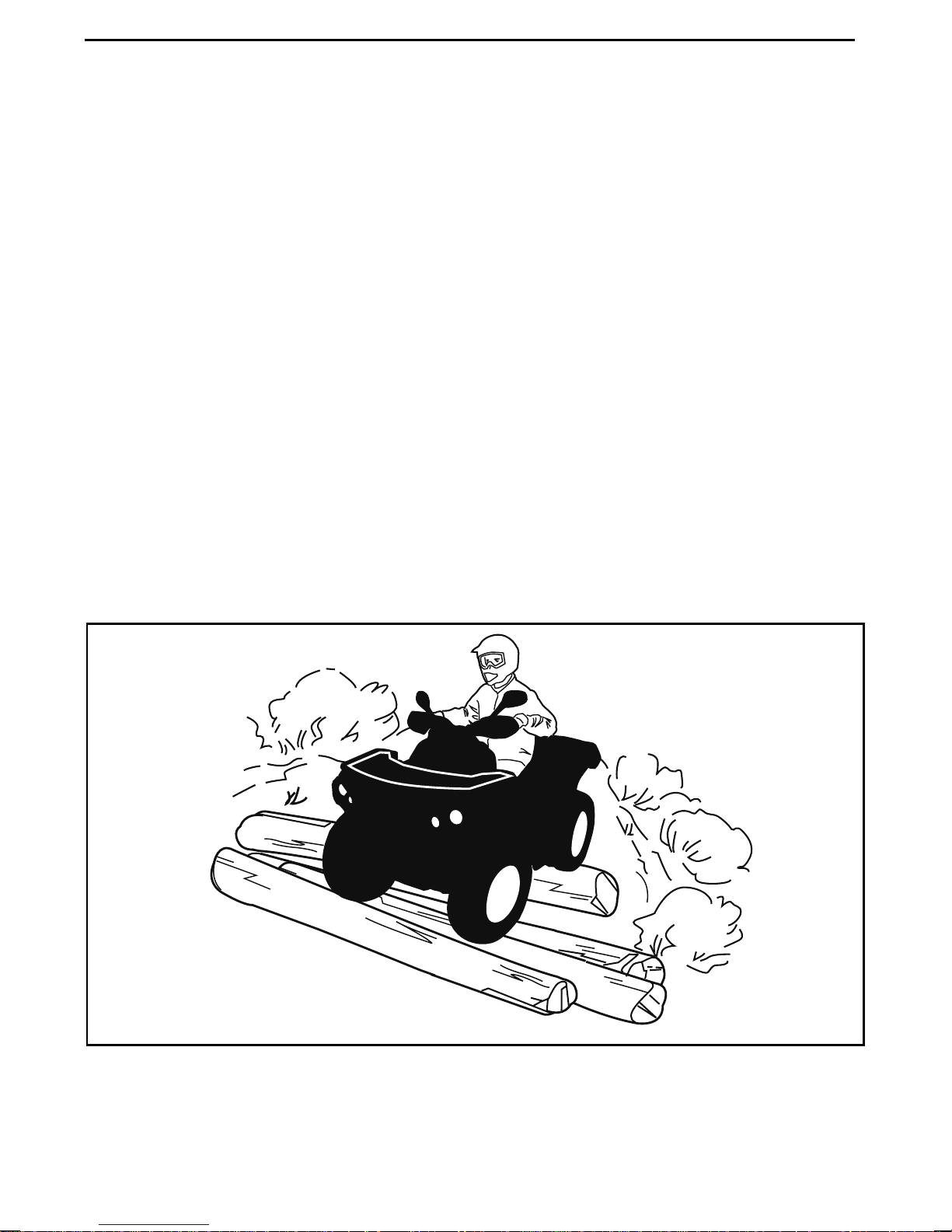
This vehicle is not designed for jumping, nor can it fully absorb the high impact
energy generated during manoeuvressuchas jumping which, can b
you, the operator. Performing “wheelies“ can cause the vehicle to flip over onto
you. Both practices have a high risk for you and should be avoided at all times.
To maintain proper control, it is strongly advised that you keep your hands on the
handlebar and within easy reach of all controls. The same holds true for your feet.
To minimize the possibility of a leg or foot injury, k e
at all times. Do not direct your toes outwards nor extend your feet out to assist in
turning as they can be hit or be snagged on passing obstacles, or may come into
contact with wheels.
ep your feet on the footrests
icle is heavy!
epassedonto
vmo2012-012-520
46
_______
SAFETY
INFORMATION
________
Page 49
RIDING THE VEHICLE
Even though there is an adequate suspension system on this vehicle, there are
“washboard” or rough terrain conditions that will make you feel uncomfortable
and can even cause a back injury. “Posting“ or riding in a crouched position will
often be required. Slow down and allow your flexed legs to absorb part of the
impact energy.
This vehicle is not designed for riding on roads or highways. (In most places it is an
illegal practice). Riding your vehicle on roads or highway s could cause a collision to
occur w ith another vehicle.
The tires of this vehicle are not suited for paved road use. Also, this vehicle is
not equipped with a rear differential (rear wheels are always turn
speed). For these reasons, pavement may seriously affect the handling and
control of the vehicle.
Riding on roads or soft shoulders may confuse other road users, especially if your
daytime running lights are on.
If you have to cross a road, the lead driver should get off his vehicle, then observe
and give directions to the other riders. The last person after crossing then assists
the lead driver to cross. Do not travel on sidew a lks. Th
pedestrian use.
ey are designated for
ing at the same
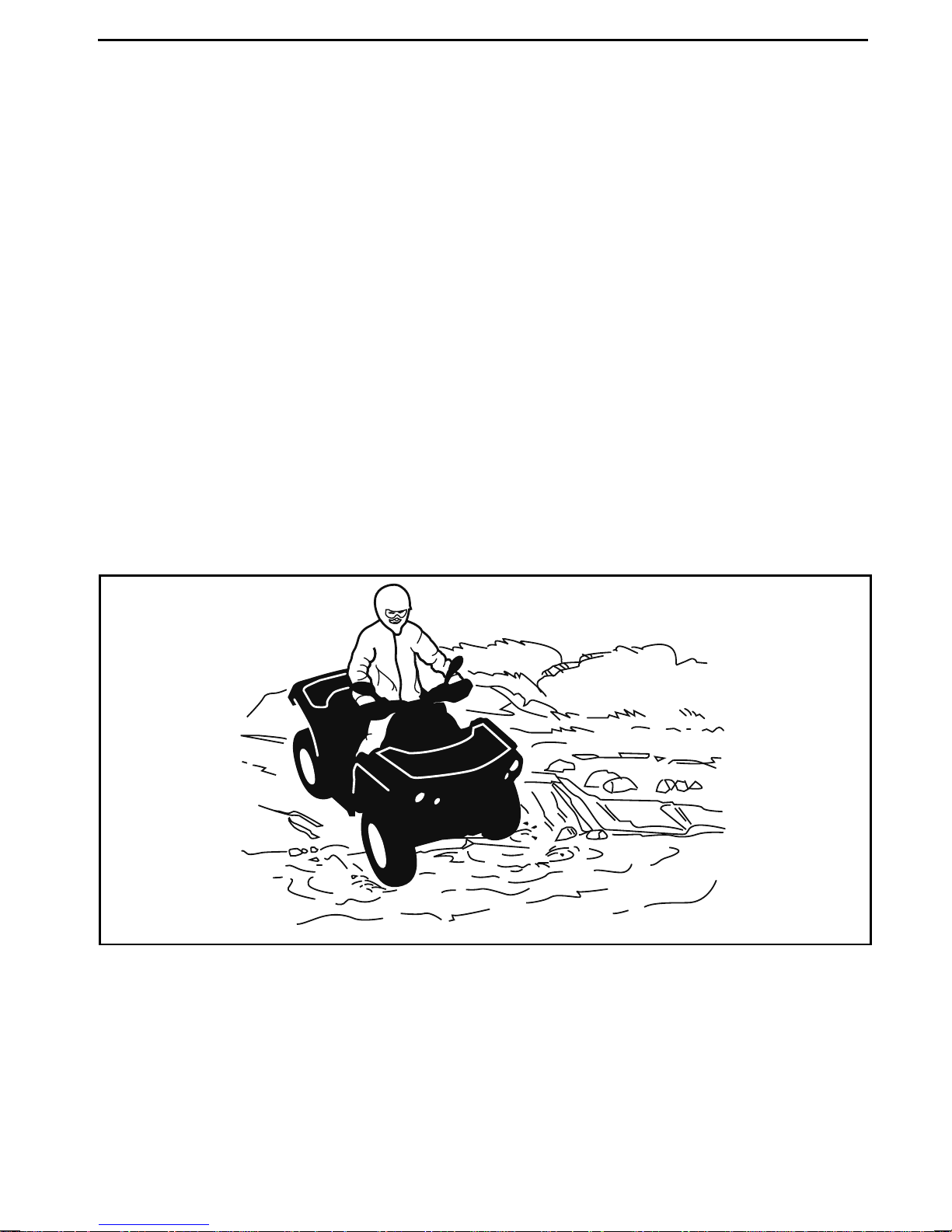
This vehicle is not designed to cross waterways.
vmo2012-012-524
Wet brakes will affect the braking ability of your vehicle. Make sure you dry the
brakes by applying them several times after the vehicle leaves the water, mud or
snow.
Mud or marsh lands may be encountered near water. Be prepared for sudden
“holes“ or changes in depth. Similarly so, be watchful of hazards such as rocks,
logs, etc., partially covered by vegetation.
________
SAFETY IN
FORMATION
________
47
Page 50

RIDING THE VEHICLE
If your route crosses frozen waterways, make sure the ice is thick enough and
sound enough to support the total weight of yourself, the vehicle and its load. Be
ever watchful of open water... it is a sure indication that the ice thickness will
If in doubt, do not attempt to cross.
Ice will also affect the control of the vehicle. Slow down and do not “gun“ the
throttle. This will only result in spinning of the tires and the vehicle may possibly
tip over. Avoid rapid braking. This again can result in an uncontrolle d slide and the
vehicle may possibly tip over. Slush should be avoided at all times since it co
block the operation or controls of the vehicle.
vary.
uld
Riding in snow may reduce the brakes stopping capability. Safely r
and allow greater distance for braking. Snow projection may cause ice build up or
snow accumulation on brake components and controls. Apply brakes frequently
to prevent ice o r snow accumulation. Refer to General Operatin
Precautions in this subsection for more detailed information regarding riding on
snow Covered surfaces.
Riding on sand, sand dunes, or on snow is another unique experience, but there
are some basicprecautionsthatshould be observed. Wet, deep or finesand/snow
may create a loss of traction and cause the vehicle to
“bogged“ down. If this occurs, look for a firmer base. Again, the best advice is to
slow down and be watchful of the conditions.
When riding in sand dunes it is advisable to equip the vehicle with an antenna type
safety flag. This will help make your location more visible to others over the next
sand dune. Proceed carefully should you see anot
antenna type safety flag can snag and rebound on your body if caught, do not use it
in areas where there are low hanging branches or obstacles.
Riding on loose stones or gravel is very similar to riding on ice. They will affe ct
the steering of vehicle... possibly causing it to slide and tip over es pe cia lly at
high speeds. In addition, braking distan
“gunning“ the throttle or sliding may cause loose stones to be ejected rearwards
into the path of another rider. Never do it deliberately.
ce may be a affected. Remember that
her safety flag ahead. Since the
slide, drop off, or become
educe speed
gandSafety
48
_______
SAFETY
INFORMATION
________
Page 51
RIDING THE VEHICLE
vmo2012-012-525
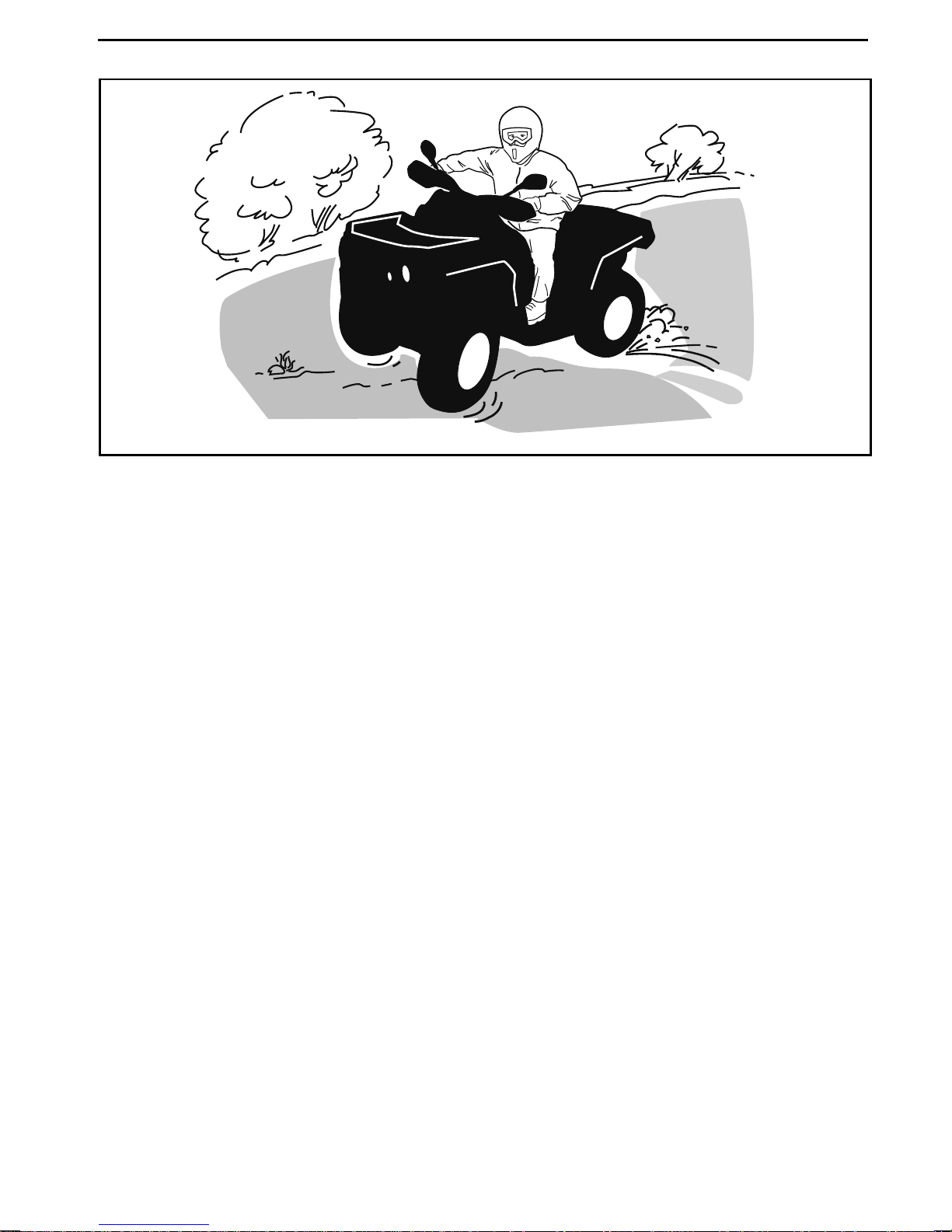
If you do get into a slide or skid, it may help to turn the handle bar in t he direction of
the skid until you regain control. Never jam the brakes and lock the wheels.
Respect and follow all posted trail signs. They are there to help you and others.
Obstacles in the “trail“ should be traversed with caution. This includes loose
rocks, fallen trees, slippery surfaces, fences, posts, and embankments and
depressions. You should avoid them whenever possible. Remember that some
obstacles are too large or dangerous to cross and should be avoided. Small rocks
or fallen trees may be safely crossed... approach at a 90° angle. Stand on the
footrests while keeping your knees flexed. Adjust speed without losing momentum and do not “gun“ the throttle. Hold handlebar firmly. Place your body weight
rearwards and proceed. Do not try to lift the vehicle front wheels off the ground.
Be a wa re that the object ma y be slippery or may move while crossing.
When driving on hills or slopes two things are highly important: be prepared
for slippery surfaces or terrain variations and obstacles and... use proper body
positioning.
When stopped or parked always apply the parking device. This is especially important when parking on a slope. On very steep inclines or if the ATV is carring cargo,
the w heels should be blocked using rocks or bricks.
________
SAFETY IN
FORMATION
________
49
Page 52
RIDING THE VEHICLE
Uphill
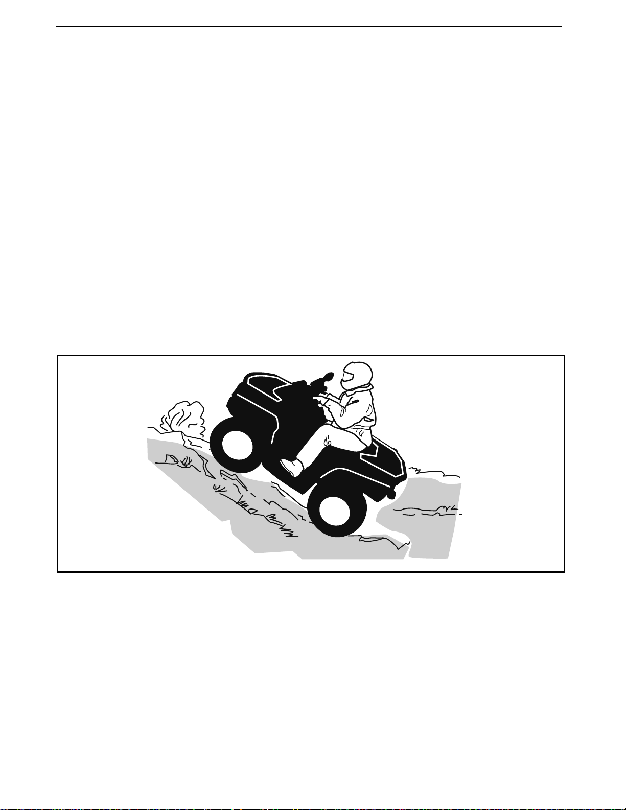
Before trying to climb a hill, keep the se things in mind. Hill Climbing should only
be attempted by experienced operators. Start on shallow slopes. Always drive
straight uphill and keep your body weight forward tow ard s the top of the hill.
Keep your feet on the footrests, shift your ATV into a lower gear and accelerate
before you start to climb. Try to keep a steady speed and go easy on the throttle
to avoid acceleration. Abrupt slope or terrain variation or r o lling one wheel over
an obstacle could have a big impact on the stability as it will lift the fro nt of
vehicle increasing th e risk of tipping o ve r. Som e hills are too steep to safely stop or
recover from after an unsuccessful climbing attempt. Try to avoid steep inclines.
If you're not c areful, you could tip over when going up hills. If
and you cannot proceed or the vehicle begins to roll backwards, apply the brake,
being careful not to slide. Dismount then use the “K” turn (while walking back,
next to the vehicle on the up hill side and with a hand on the br
back the rear of the vehicle toward the top o f the hill then drive downhill). Always
walk or dismount on the upside of the slope while keeping clear of the vehicle and
its rotating wheels. Do not try to hold on to the ve
clear. Do not ride over the crest of the hill at high speed. Obstacles, including
sharp drop-offs, may exist.
hicle if it begins to topple. Stay
the hill is too steep
ake lever, slowly
the
vmo2012-012-526
50
_______
SAFETY
INFORMATION
________
Page 53
RIDING THE VEHICLE
Downhill
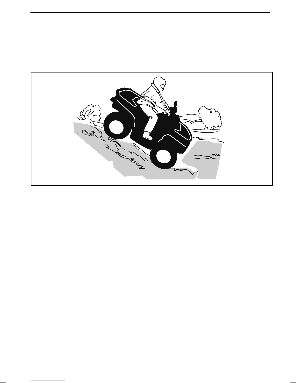
Keep your body weight rearwards. Apply the brake gradually to prevent skidding.
Do not “coast“ down the slope using solely engine compressionor in neutral gear.
Try to avoid steep inclines. If you're not careful, you could tip over when going
down hills.
vmo2012-012-523
________
SAFETY IN
FORMATION
________
51
Page 54
RIDING THE VEHICLE
Side Hilling
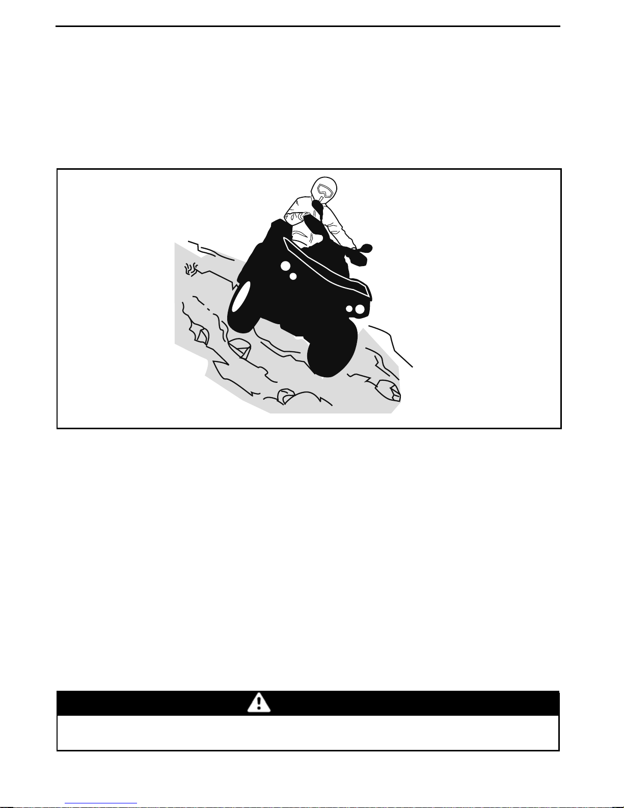
This is one of the most risky types of riding since it may drastically change the balance of the vehicle. It should be avoided wherever possible. However, if it is necessary to do so, it is important that you ALWAYS keep your body weight on the upside of the slope... and be prepared to dismount on that side should the vehicle be
gin to topple. Do not try to stop or save the vehicle from damage.
-
vmo2012-012-527
While reading this Operator’s Guide, remember that:
WARNING
Indicates a potential hazard that, if not avoided, could result in serious
injury or death.
52
_______
SAFETY
INFORMATION
________
Page 55
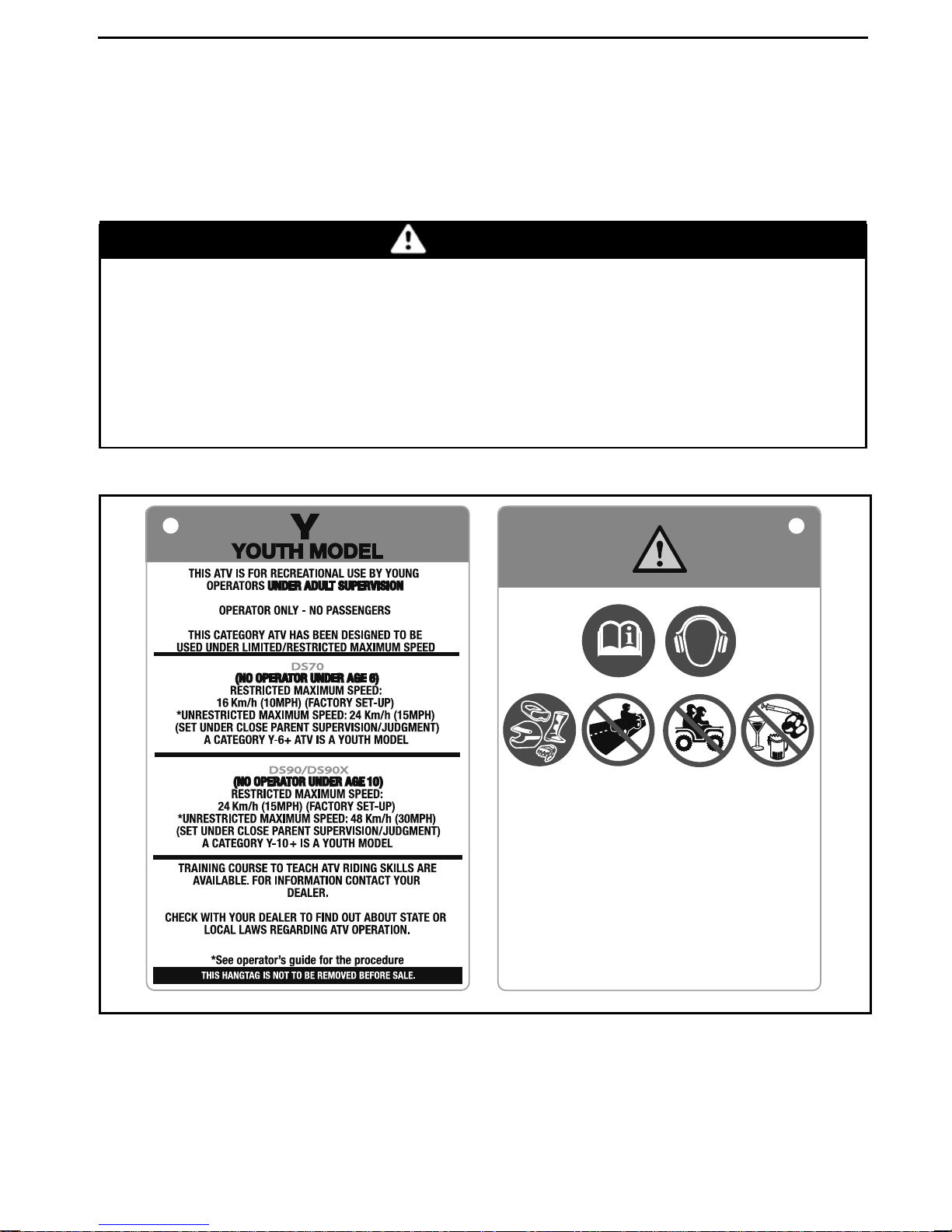
IMPORTANT ON PRODUCT LABELS
Hang Tag
This vehicle comes with a hang tag containing important information.
Any person who rides this vehicle should read and understand this information be-
fore riding.
WARNING
– Locate and read operator's guide. Improper ATV use can result in SE-
VERE INJURY o r DEATH. Follow all instructions and warning s.
– Always wear ear protection.
– Always use an approved helmet and protective gear.
– Never use on public roads.
– Never carry p assengers.
– Never use with drugs or alcohol.
704903392A
TYPICAL
________
SAFETY IN
FORMATION
704903932
________
53
Page 56
IMPORTANT ON PRODUCT LABELS
704901107
vmo2006-005-009_en
54
_______
SAFETY
INFORMATION
________
Page 57
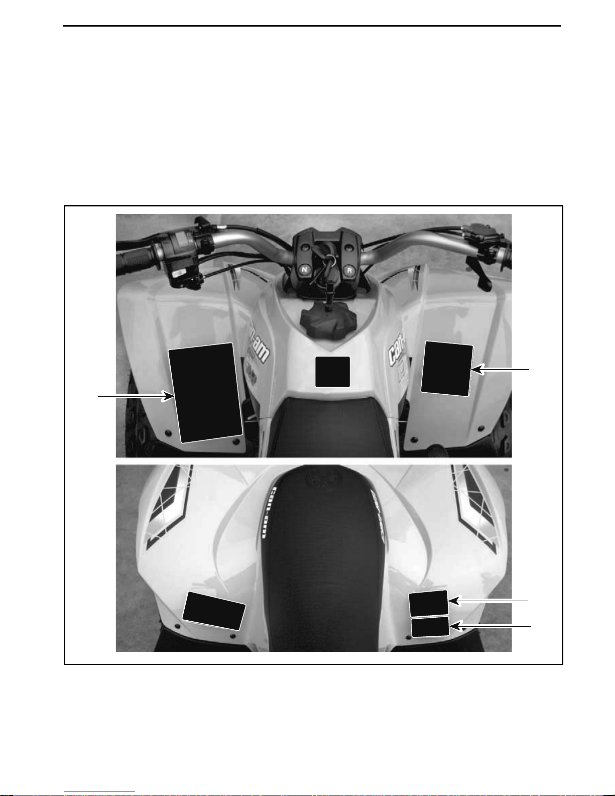
Vehicle Safety Labels
IMPORTANT ON PRODUCT LABELS
Read and understand all the safety labels on your vehicle. These labels are affixe
to your vehicle for the safety of the operator or bystanders.
The safety labels on your vehicle should be considered permanent parts of the vehicle. If missing or damaged, they can be replaced free of charge. See an authorized Can-Am dealer.
NOTE: In the event of any discrepancy between this guide and the vehicle, the
safety labels on the vehicle have precedence over the labels in this guide.
d
3
1
vmo2010-003-002_c
TYPICAL - LABEL LOCATIONS
2
4
________
SAFETY IN
FORMATION
________
55
Page 58
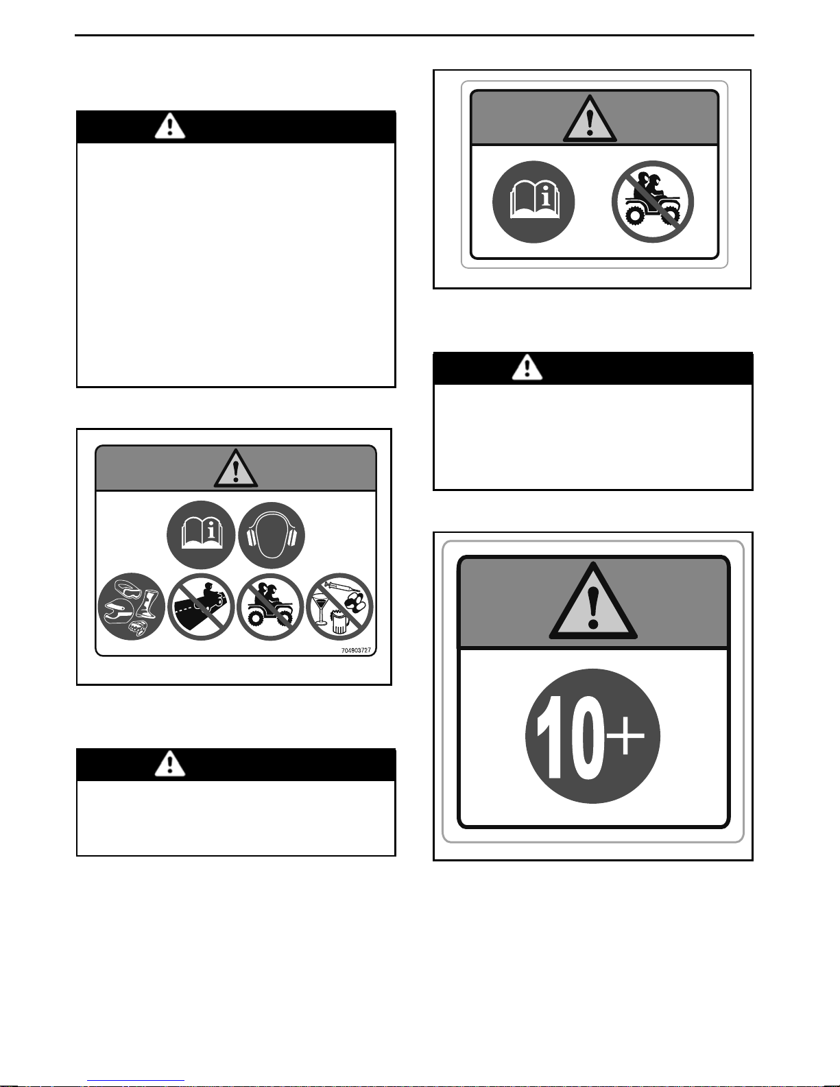
IMPORTANT ON PRODUCT LABELS
Label 1
WARNING
– Locate and read operator's
guide. Improper ATV use can
result in SEVERE INJURY or
DEATH. Follow all instructions
and w arnings.
– Always wear ear protection.
– Always use an approved helmet
and protective gear.
– Never use on public roads.
– Never carry passengers.
– Never use with drugs or alcohol.
704903684
704903684
LABEL 2
Label 3
WARNING
Operating of this ATV if you are under the age of 10 increases your
chance of SEVERE INJURY OR
DEATH. NEVER operate this ATV
if you are under age 10.
704903727A
LABEL 1
Label 2
WARNING
– Locate and read operato
guide.
– NEVER carry a passenger.
56
_______
SAFETY
r's
704903805A
LABEL 3
INFORMATION
704903805
________
Page 59
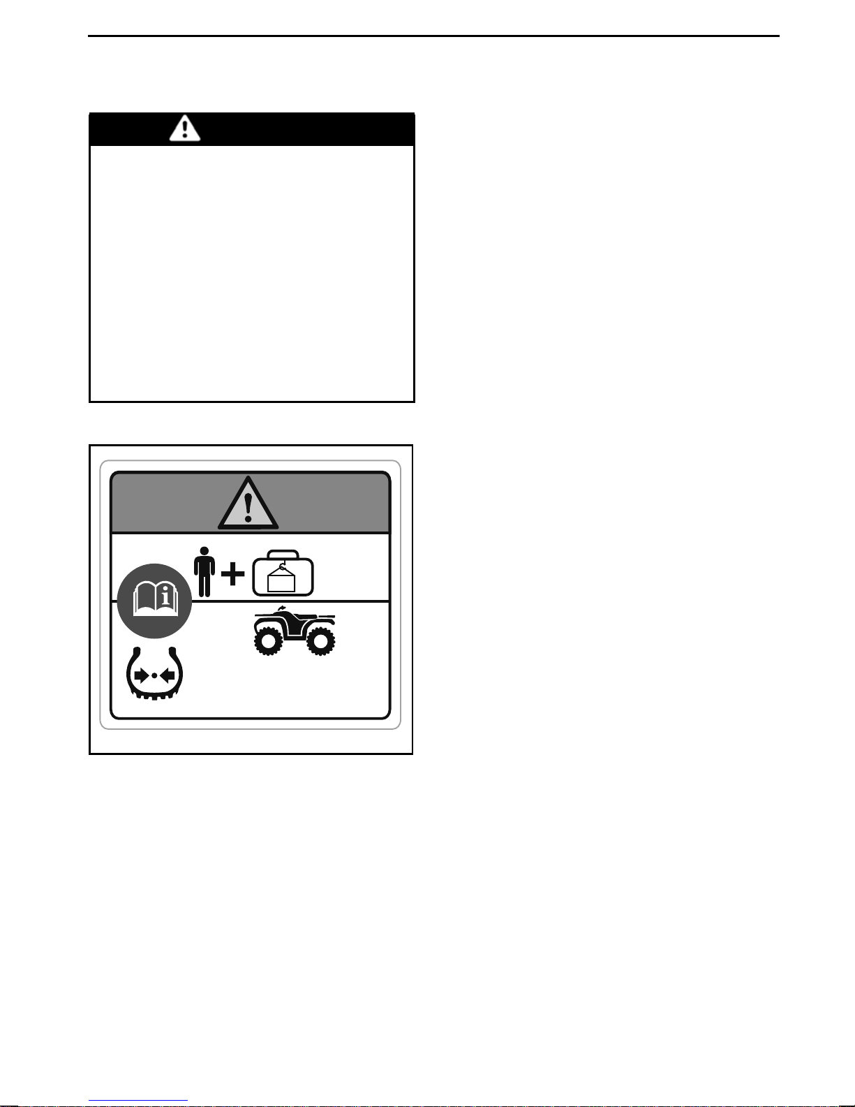
Label 4
WARNING
– Locate and read operator's
guide.
– Improper overloading or tire
pressure can cause loss of control, resulting in SEVERE INJURY or DEATH.
– ALWAYS maintain proper tire
pressure as shown.
– NEVER exceed the vehicle load
capacity of 70 kg (150 lb), including weight of operator and
accessories.
IMPORTANT ON PRODUCT LABELS
704903806A
LABEL 4
kPa
MAX: 35 kpa
(5 psi)
=
MIN: 25 kpa
(3.6 psi)
< 70 kg MAX.
(150 lb)
MAX: 35 kpa
(5 psi)
MIN: 25 kpa
(3.6 psi)
704903806
________
SAFETY IN
FORMATION
________
57
Page 60
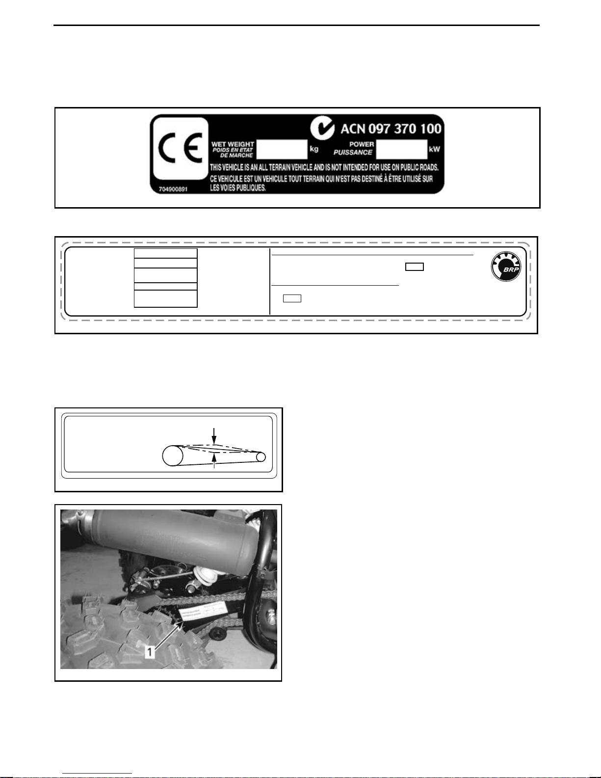
IMPORTANT ON PRODUCT LABELS
Compliance Labels
These labels indicate vehicle's compliance.
V00m03y2
LOCATION: LOWER RIGHT FRONT TUBE OF THE FRAME
ENGINE FAMIL Y
PERMEATION F AMILY
CERTIFICATION
STANDARD (FEL)
ENGINE DISPLACEMENT
EXHAUST EMISSION
CONTROL SYSTEM
BOMBARDIER RECREATIONAL PRODUCTS INC.
vmo2015-500
FAMILLE DE MOTEUR
FAMILLE DE PERMEA TION
LIMITE DES ÉMISSIONS
DE LA FAMILLE
CYLINDRÉE
SYSTÈME DE CONTRÔLE
DES ÉMISSIONS
LOCATION: UNDERNEATH REAR FENDER
Technical Information
Label
44 - 57 mm (1-3/4 to 2-3/4)
CHAIN PLAY ADJUSTMENT
AJUSTEMENT DE LA CHAÎNE
87604-DGF-00H
vmo2011-004-001_a
RENSEIGNEMENTS SUR LE DISPOSITIF ANTIPOLLUTION
CE VÉHICULE EST CERTIFIÉ POUR FONCTIONNER À L'ESSENCE
SANS PLOMB ET IL RÉPOND AUX NORMES DE L'EPA
POUR LES VTT À MOTEUR SI
EMISSION CONTROL INFORMATION
THIS VEHICLE IS CERTIFIED TO OPERATE ON UNLEADED GASOLINE AND MEETS
TO U.S. EPA FOR ATV SI ENGINES
SEE OPERATOR’S GUIDE FOR MAINTENANCE SPECIFICATIONS
VOIR GUIDE DU CONDUCTEUR POUR LES SPÉCIFICATIONS D’ENTRETIEN
.
.
vmo2011-004-002_a
1. Ch ain adjustment label location
58
_______
SAFETY
INFORMATION
________
Page 61

VEHICLE
INFORMATION
_______________
59
Page 62
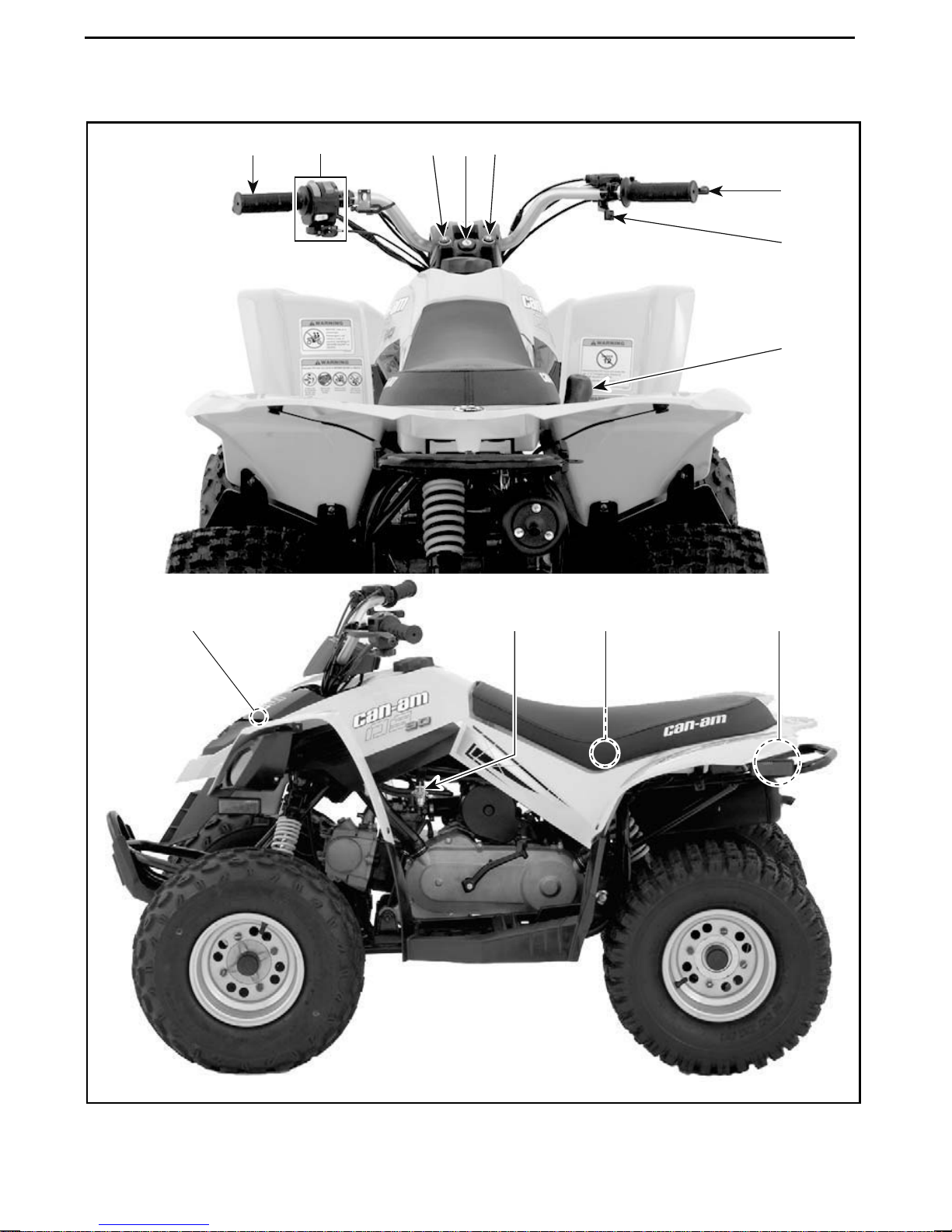
CONTROLS/INSTRUMENTS/EQUIPMENT
3,4
6 7 8 7
2
1
5
12
9
11
10
vmo2010-003-1
TYPICAL
60
01_b
______________
Page 63
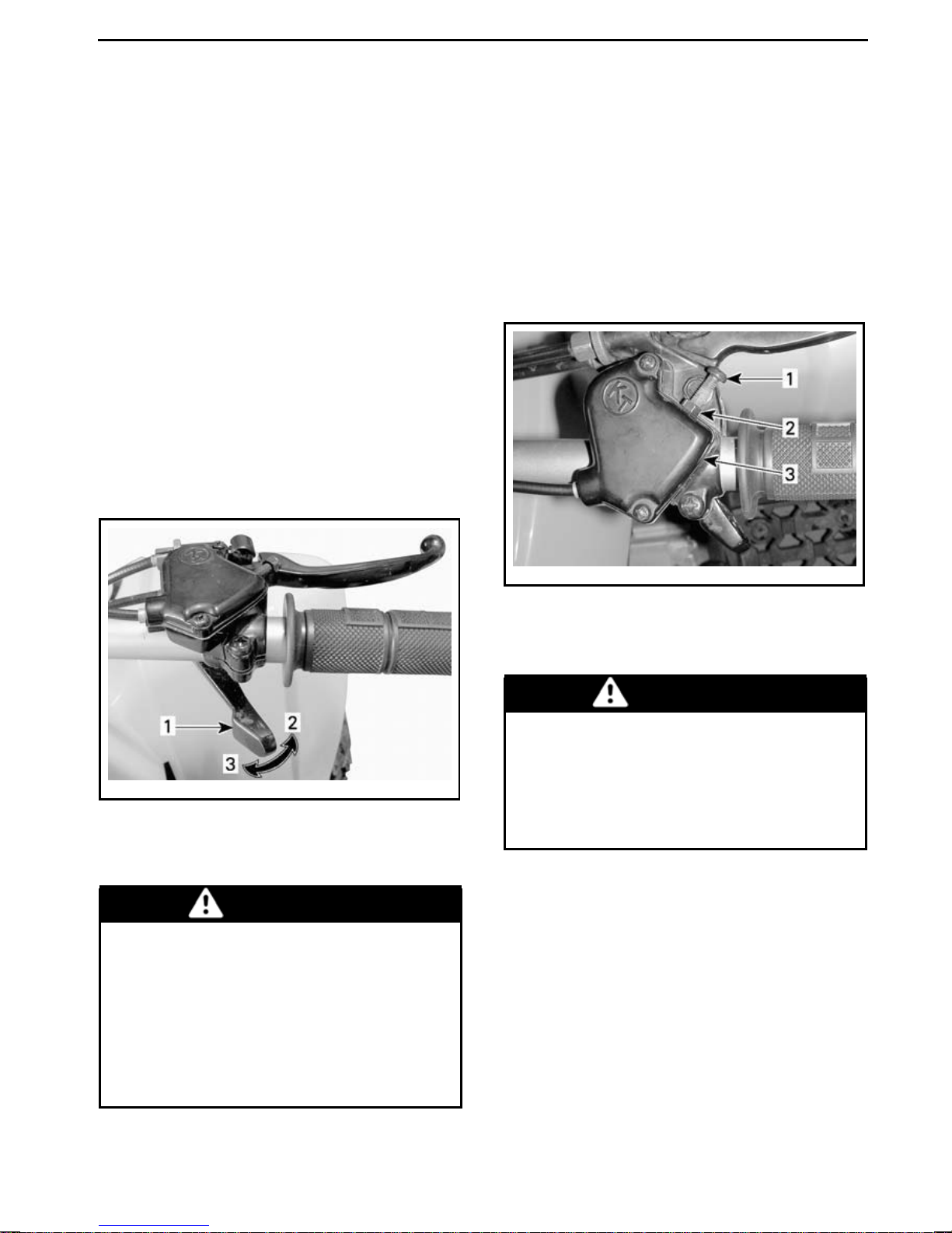
CONTROLS/INSTRUMENTS/EQUIPMENT
NOTE: This section provides basic
information on the functions of the various controls of your vehicle. For more
details on how to operate a control in
conjunction with others, refer to
ERATING INSTRUCTIONS
further in
OP-
this section.
1) Throttle Lever
The throttle lever is located on the RH
side of the handlebar.
When pushed forward, it increases the
engine speed and allows engagement
of the transmission.
When released, the engine speed
should automatically return to idle and
the vehicle will gradually slow down.
Speed Limiter
This vehicle is equipped with an adjustable spe e d limiter screw o n the
throttle lever housing. The speed limiter prevents the throttle from being
fully opened, even when the throttle
lever is pushed fully forward, thus limiting available engine power and therefore vehicle speed.
vmo2008-020-003_a
TYPICAL
1. Throttle lever
2. To accelerate
3. To decelerate
WARNING
Check throttle lever operation before you start the engine. If the
throttle lever does not function
smoothly, check for the cause.
Correct the problem before riding the vehicle. Consult your authorized dealer if you can't find or
solve the problem yourself.
vmo2008-020-004_a
TYPICAL
1. S peed limiter screw
2. Lock nut
3. Throttle lever cable housing
WARNING
Adults should always limit the maximum restricted speed within the
ability and capacity of the child to
operate the vehicle safely. Never
allow the child to adjust the sp e ed
limiter screw.
BRP recommends that all beginners
start off with the speed limiter screw
turned in while they learn.
Adults can adjust the speed limiter
screw gradually to increase maximum
speed as the beginner becomes m ore
familiar with the operation of the vehicle. Refer to the following table.
_______________
61
Page 64
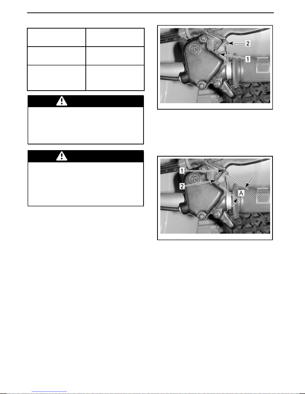
CONTROLS/INSTRUMENTS/EQUIPMENT
SPEED SETTING
Factory limited
speed
Maximum
unrestricted
speed
DS 90 AND
DS 90 X
24 km/h (15 MPH)
48 km/h (30 MPH)
WARNING
When traveling downhill, gravity can increase the vehicle speed
above the desired maximum
speed set using the speed limiter
screw.
WARNING
Improper adjustment of the speed
limiter screw could damage the
throttle cable and impair throttle lever operation. Failure to follow adjustment recommendations
couldleadtoanaccident.
vmo2008-020-004_b
1. Lock nut
2. S peed limiter screw
To obtain maxim um vehicle speed, adjust the throttle lever travel to 9 mm
(11/32 in).
To adjust the sp eed limiter screw,
loosen the lock nut, then turn the
speed limiter screw accordingly. Turning the screw clockwise reduces throttle lever travel, turning the screw
counter clockwiseincreases throttle
lever travel.
vmo2008-020-004_c
1. S peed limiter screw
2. Lock nut
A. Maximum throttle lever trave l
9 mm (11/32 in)
adjustment
2) RH Brake Lever
The RH brake leverislocatedon the RH
side of the handlebar.
When pulled in, the front brake is applied. When released, it s
matically return to its original position.
Braking effect is proportional to the
forceappliedonthelev
hould auto-
er.
62
______________
Page 65
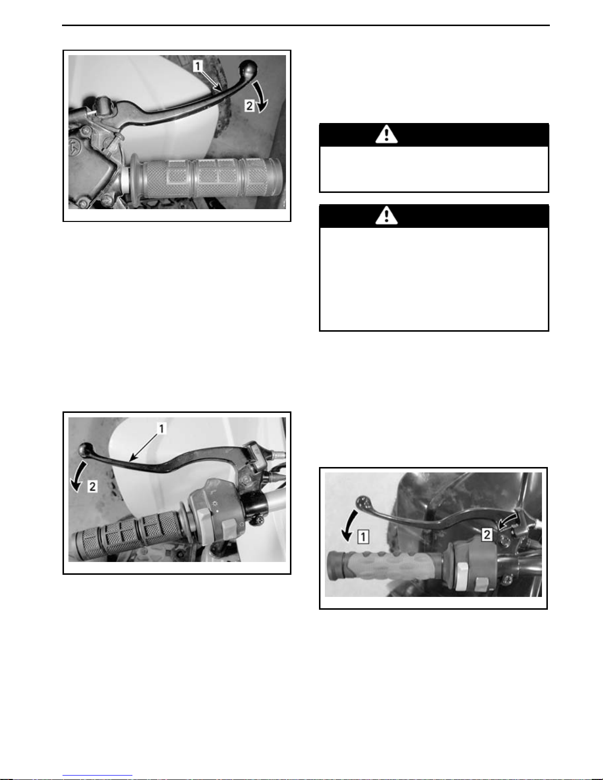
CONTROLS/INSTRUMENTS/EQUIPMENT
When applied, it prevents the vehicle from moving. Useful during transportation or when the vehicle is not in
operation.
WARNING
Always use the parking brake
when the vehicle is not in operation.
vmo2008-020-005_a
TYPICAL
1. Brake lever
2. To apply brake
3) LH Brake Lever
The LH brake lever is located on the LH
side of the handlebar.
When pulled in, the rear brake is applied. When released, it should automatically return to its original position.
Braking effect is proportional to the
forceappliedonthelever.
WARNING
Make sure the parking brake is
fully disengaged before operating the vehicle. Riding the vehicle
with a continuous pressure on the
brakes may cause damage to the
brake system and a loss of braking
capacity and/or fire.
To engage the parking brake mechanism: Squeeze the LH brake lever and
hold as you engage the lever lock, then
release the lever against the lock. The
brake lever is now held in applying the
rear brake(s).
DS 90
vmo2008-020-006_a
TYPICAL
1. Brake lever
2. To apply brake
4) Parking Brake
The parking brake is located on the LH
side of the handlebar.
vmo2008-008-008_b
TYPICAL — LH BRAKE LEVER
Step 1: S queez e brake lever and hold
Step 2: Engage lever lock
_______________
63
Page 66
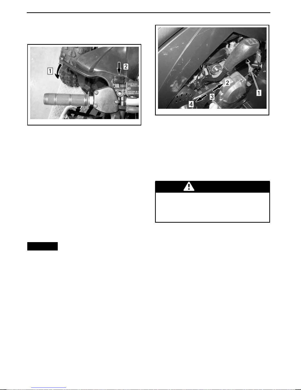
CONTROLS/INSTRUMENTS/EQUIPMENT
DS 90 X Only
vmo2008-020-014_a
LH BRA KE LEVER
Step 1: Squeeze brake lever and maintain
Step 2: Push lever lock
vmo2008-008-018_a
TRANSMISSION LEVER PATTERN
1. Transmission lever
2. Forward (F)
3. Neutral (N)
4. Reverse (R)
All Models
To release the parking brake mechanism: Squeeze bra ke lever. Lever
lock should automatically return to its
original position. Brake lever should
return to rest position. A lways rele ase
parking brake before riding.
5) Transmission Lever
A 3 position transmission lever is located on the RH side of the vehicle
near the engine.
NOTICE
the vehicle and apply the brakes
prior to moving the transmission
lever.
Always completely stop
To change the transmission position,
completely stop vehicle, apply brakes,
then move lever to the desired position. Do not force lever.
WARNING
Before moving vehicle in reverse,
ensure the path behind is clear of
obstacles or bystanders. Remain
seated.
F: Forward
It is the normal driving range. It allows the vehicle to rea ch its maximum
speed.
N: Neutral
This position disengages the transmission to allow manual vehicle movement or towing.
64
______________
R: Reverse
This allows the vehicle to go backwards.
Page 67
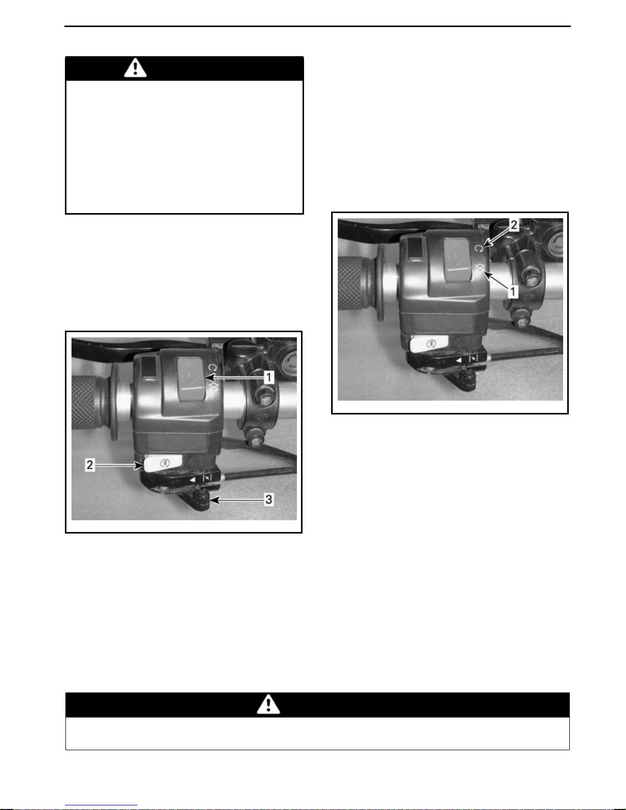
CONTROLS/INSTRUMENTS/EQUIPMENT
WARNING
Before operating the vehicle in reverse, ensure the path behind is
clear of obstacles or bystanders.
BRP recommends that you remain
seated. Avoid standing up. Your
weight could shift forward against
the throttle lever causing an unexpected acceleration and loss of
control.
6) Multifunction Switch
The multifunction switch is loc ated on
the LH side of the handlebar.
The controls located on the multifunction switch are:
NOTE: While the engin e can be
stopped by turning the ignition key
to the OFF position, we recommend
the engine be stopped by setting the
emergency engine stop switch to the
STOP position.
To stop engine, fully release throttle
lever, then set the emergency engine
stop switch to the STO P position.
vmo2009-004-005_e
TYPICAL - EMERGENCY ENGINE STOP
SWITCH
1. STOP position
2. RUN position
Engine Start Button
To start engin e, place the emergency
vmo2009-004-005_a
1. E me rgency engine stop switch
2. Engine start button
3. Ch oke lever
enginestopswitchtotheRUNposition.
Press and hold LH brake lever.
Press and hold the engine start button.
Emergency Engine Stop Switch
Release imm ediately afte r engine
started.
This switch can be used to stop the engine, and as an emergency control.
While reading this Operator’s Guide, remember that:
is
Indicates a potential hazard that, if not avoided, could result in serious
injury or death.
WARNING
_______________
65
Page 68
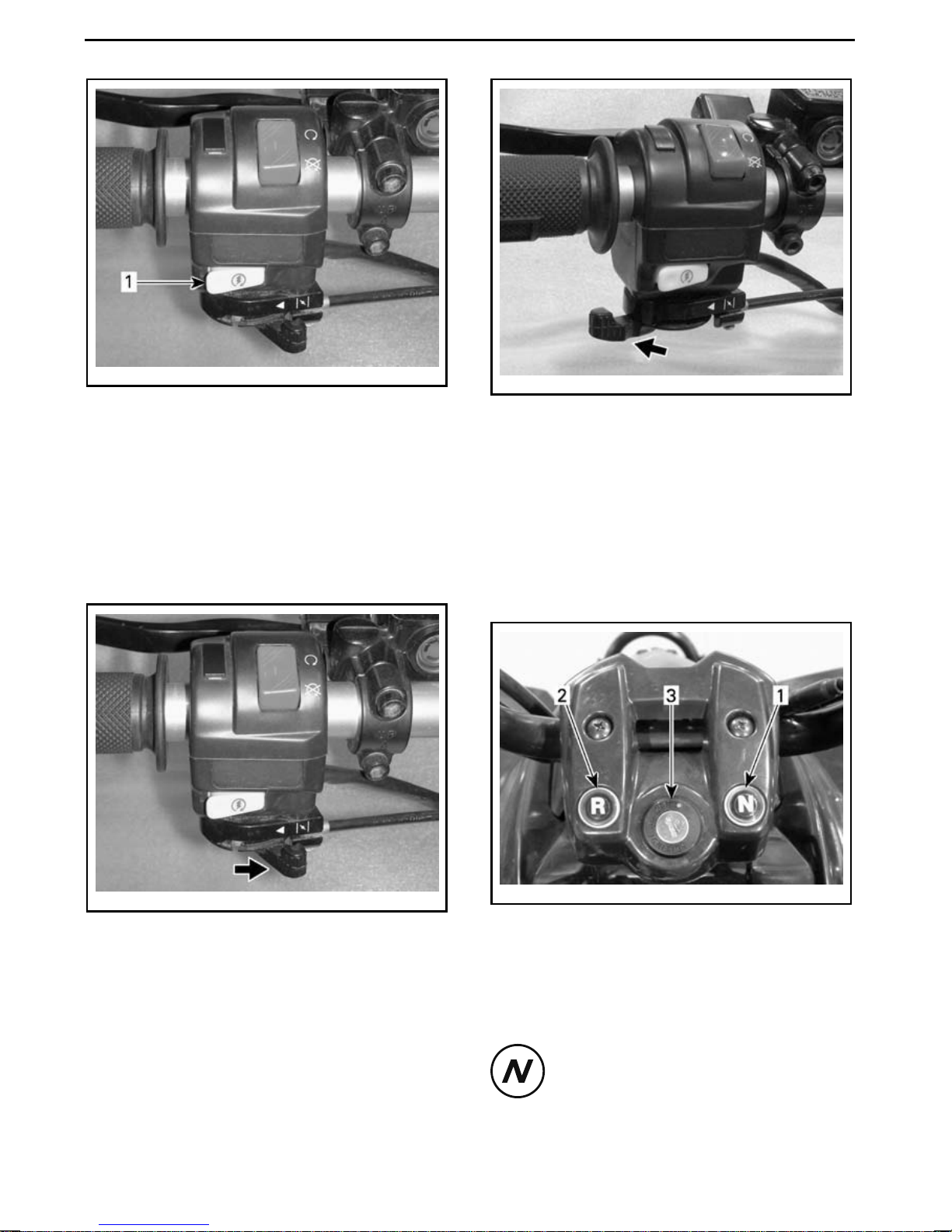
CONTROLS/INSTRUMENTS/EQUIPMENT
vmo2009-004-005_c
1. Engine start button
Choke Lever
This device features a variable positio n
lever used to ease starting a cold engine.
The OFF position is used when the engine is warm.
vmo2009-004-006_a
FULL CHOKE POSITION
The other positions between OFF and
FULL will be used depending on the
engine temperature.
7) Indicator Lamps
The indicator lamps are located near
the middle of the handlebar.
vmo2009-004-005_d
OFF POSITION
The full choke position is used when
theengineiscold.
66
______________
vmo2008-008-019_a
TYPICAL
1. Neutral (N)
2. Reverse (R)
3. Ignition switch
Neutral Lamp (GREEN)
When lit, it indicates the
transmission is in neut
position.
ral
Page 69
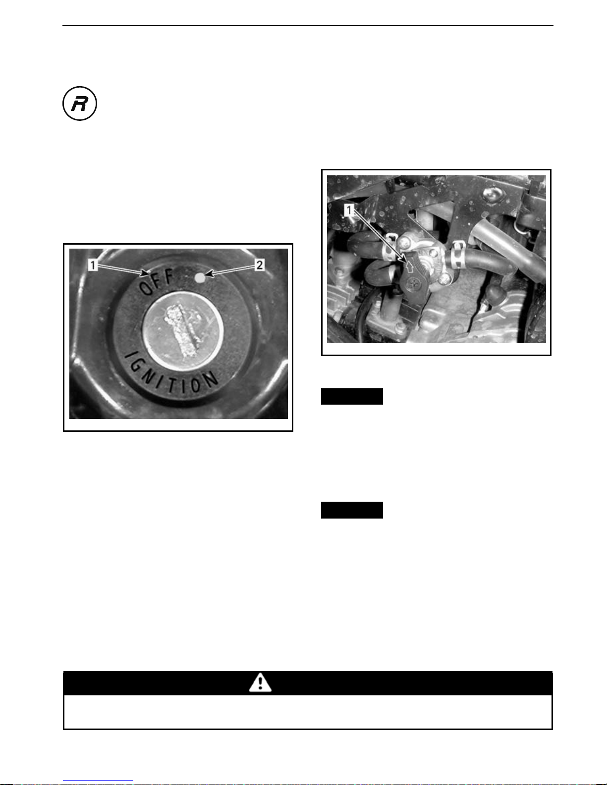
CONTROLS/INSTRUMENTS/EQUIPMENT
Reverse Lamp (RED)
When lit, it indicates the
transmission is in reverse
position.
8) Ignition Switch
The ignition switch is located in the
middle of the handlebar.
It is a key-operated, 2 position switch:
OFF and ON.
9) Fuel Valve
The fuel valve is located on the LH side
of the vehicle near the engine.
This is a 3 position rotary valve: OFF,
ON, RES (reserve). Ro tate the valve to
align its arrow to the desired position.
vmo2013-004-005_a
LH SIDE OF VEHICLE
1. Align this arrow toward the desired position
NOTICE
valve will restrict the flow of fuel.
vmo2008-008-012_a
IGNITION SWITCH
1. OFF p osition
2. ON position
Insert key in switch and turn to ON po
Make sure valve is fully opened
when engine is running.
OFF
-
Stops fuel supply to carburetor.
sition. To remove key, turn key to OFF
position then pull it out.
NOTE: While the engin e can be
stopped by turning ignition key to OFF
position, we recommend the en
gine
be stopped using the emergency engine stop switch. Always turn ignition
switch to OFF position afte
rengine
has been stopped.
NOTICE
position as soon as the engine is
stopped.
ON
Allows fuel to flow to carburetor. This
is the normal position for operation of
the vehicle.
While reading this Operator’s Guide, remember that:
Improper opening of fuel
Turn fuel valve to OFF
Indicates a potential hazard that, if not avoided, could result in serious
injury or death.
WARNING
_______________
67
Page 70
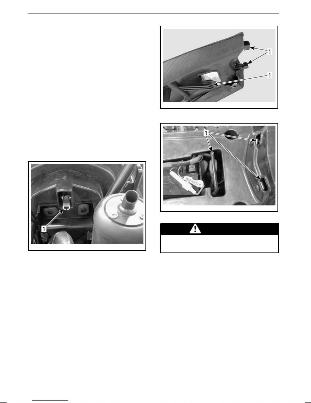
CONTROLS/INSTRUMENTS/EQUIPMENT
RES (Reserve)
When the normal supply of fuel in the
tank is used up (ON position), an emergencysupplyof fuel is availablebyturning the valve to RES. Use the RES position only when the ON supplyisempty.
When in reserve,refuelassoon as possible. Be sure to turn the valve back to
the ON position after refuelling.
10) Seat Latch
Located under the rear fender, near
rear bumper. It allows the removal
of the seat to provide access to the
engine compartment. Pull knob to release seat.
vmo2008-008-042_a
1. Seat tabs
vmo2008-008-016_a
TYPICAL
1. Seat release knob
Seat Removal
Pull latch while gently lifting rear of
seat. Pull seat rearward then remov
it.
Seat Installation
Insert front tabs of seat into frame
hooks. When seat rests in its pos
tion, firmly push seat down to latch.
vmo2008-008-043_a
1. H ooks
WARNING
Make sure seat is securely latched
before riding.
11) Tool Kit
Located underneath the seat over the
engine compartment, the tool kit con-
e
tains tools for basic m ainte
i-
nance.
68
______________
Page 71
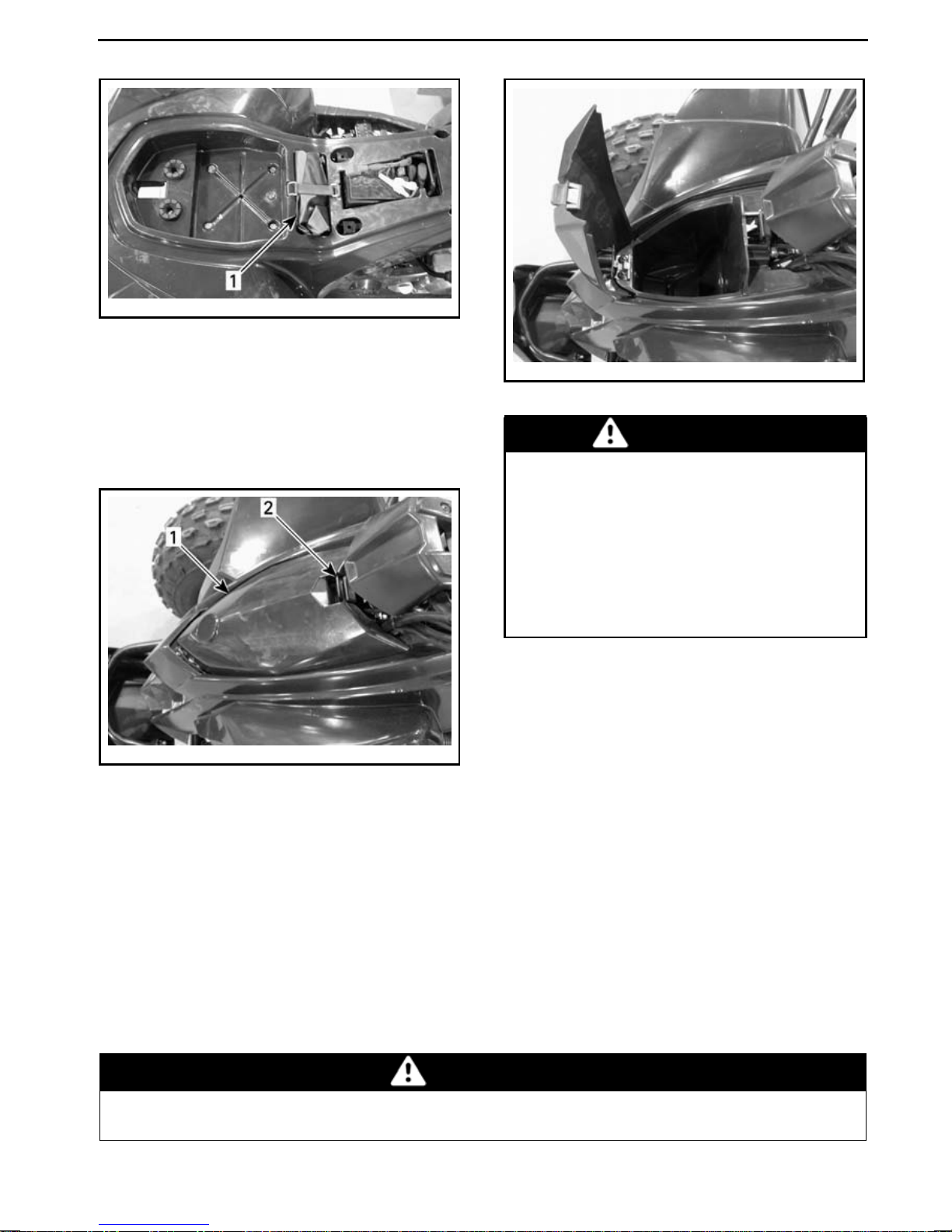
vmo2008-008-020_a
1. Tool kit
CONTROLS/INSTRUMENTS/EQUIPMENT
12) Front Storage
Compartment
A convenient area to carry personal articles.
vmo2008-008-022_a
TYPICAL
1. F ront storage compartment
2. Cover latch
vmo2008-008-023_a
TYPICAL
WARNING
When engine is running, always
engage the NEUTRAL position
on the transmission lever and apply parking brake before opening
cover. Never leave any heavy or
loose breakable object in the storage compartment. Always latch
cover before riding.
To open storage compartment cover,
gently pull and hold latch whi
cover.
While reading this Operator’s Guide, remember that:
Indicates a potential hazard that, if not avoided, could result in serious
injury or death.
le liftin g
WARNING
_______________
69
Page 72

FUEL
Fuel Requirements
NOTICE
line. Gasoline will oxidize; the result is loss of octane, volatile compounds, and the production of gum
and varnish deposits which can
damage the fuel system.
Alcohol fuel blending varies by country and region. Your vehicle has been
designed to operate using the recommended fuels, however, be aware of
the following:
– Use of fuel containing alcohol above
the percentage specified by government regulations is not recommended and can result in the following problems in the fuel system
components:
• Starting and operating difficulties.
• Deterioration of rubber or plastic
parts.
• Corrosion of metal parts.
• Damage to internal engine parts.
– Inspect frequently for the presence
of fuel leaks or other fuel system
abnormalities if you suspect the
presence of alcohol in gasoline exceeds the current government regulations.
– Alcohol blended fuels attract and
hold moisture which ma y lead to
fuel phase separation and can result
in engine performance problems or
engine damage.
Recommen ded Fuel
Use com mon unleaded gasoline with
an AKI (R+M)/2 octane rating of 87, or
an RON octane rating of 92.
Always use fresh gaso-
NOTICE
other fuels. Engine or fuel system
damages may occur with the use of
an inadequate fuel.
Never experiment with
Fueling Procedure
WARNING
– Donotallowchildrentoputfuel
in the vehicle.
– Always stop engine before refu-
eling. Open cap slowly.
– If a differential pressure condi-
tion is noticed (whistling sound
heard when loosening fuel tank
cap) have vehicle inspected
and/or repaired before further
operation.
– Fuel vapors are flammable and
explosive under certain conditions.
– Never use an open flame to
check fuel level.
– Never smoke or allow a flame or
spark in the vicinity.
– Alwaysworkinawell-ventilated
area.
– Never top off the fuel tank be-
fore placing the vehicle in a
warm area. As temperature
creases, fuel expands and may
overflow.
– Always wipe off any fuel or oil
spillage from the vehi
1. Stop engine.
2. Do not allow anyone to remain
seated on the ve
3. Unscrew fuel tank cap counterclockwisetor
hicle w hile fuelling .
emove.
cle.
in-
70
______________
Page 73
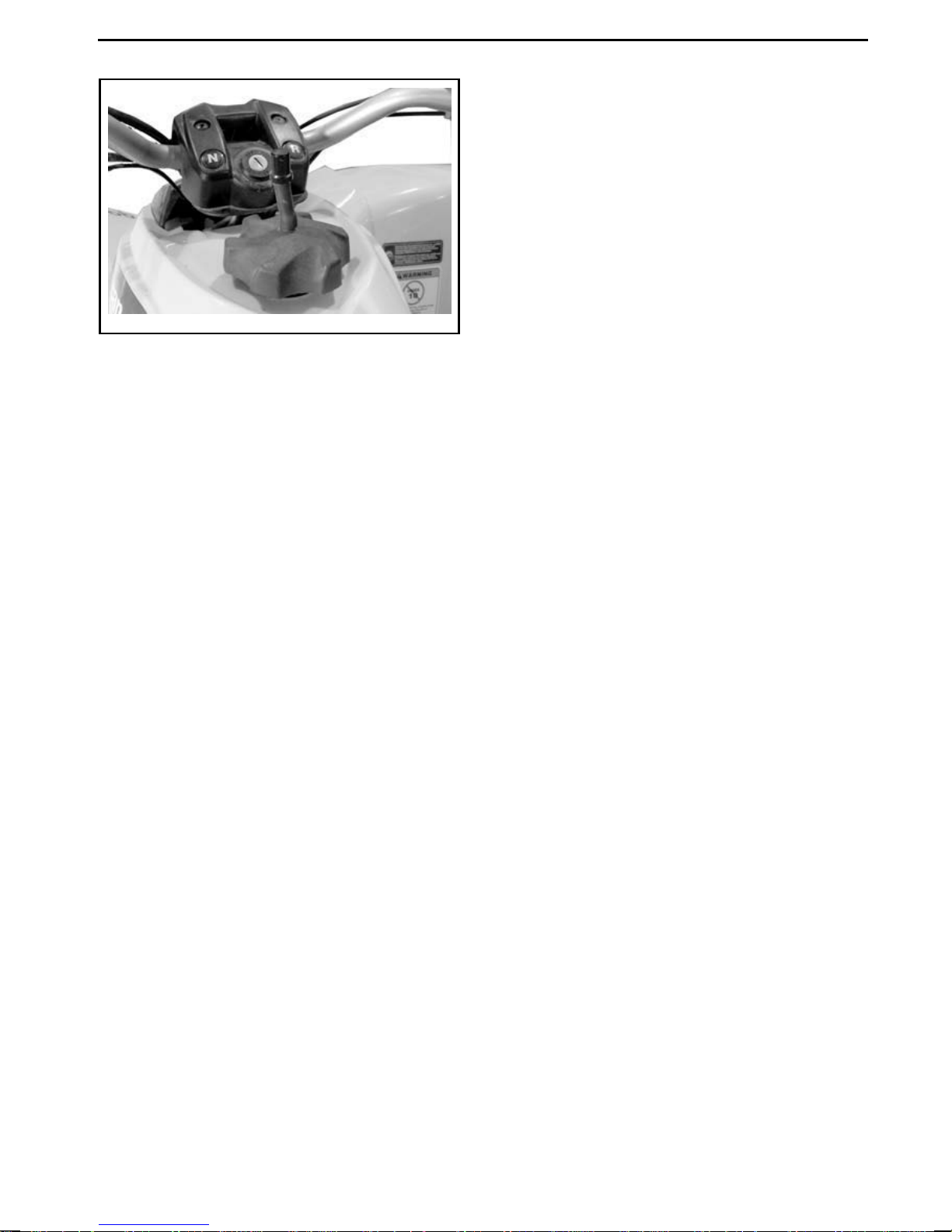
vmo2015-004-501
TYPICAL — FUEL TA NK CAP
4. Insert the sp ou t in the filler neck.
5. Pour fuelslowlytoallowtimefor the
air in the tank to escape and prevent
fuel flow back. Be careful not to spill
fuel.
FUEL
6. Stop fuelling when the fuel reaches
the bottom of filler neck. Do not
overfill.
7. Fully tighten fuel tank cap clockwise.
_______________
71
Page 74

BREAK-IN PERIOD
Operating During Break-In
A brea k-in period of 10 operating hours
is required before running the vehicle
at sustained full throttle.
After the break-in period, the vehicle
should be inspected by an authorized
Can-Am dealer. Refer to
NANCE INFORMATION
Engine
During the break-in period:
– Avoid full throttle operation.
– Maximum throttle should not ex-
ceed 3/4.
– Avoid sustained accelera tions .
– Avoid prolonged cruising speeds.
– Avoid engine overheating.
.
MAINTE-
However, brief accelerations and
speed variations contribute to a good
break-in.
Brakes
WARNING
The new brakes will not perform
to their maximum efficiency until their burnishing is completed.
To achieve a good burnishing,
bring the vehicle to a complete
stop for a minimum of 50 times
using brakes. Readjust brakes if
needed, refer to
CABLE ADJUSTM ENT
BRAKE LEVER ADJUSTMENT
Belt
A new belt requires a break-in period of
50 km (30 mi).
FRONT BRAKE
and
REAR
.
During the break-in period:
– Avoid strong accelerations and de-
celerations
– Avoid pulling a load
– Avoid high speed cruisin
72
______________
g.
Page 75
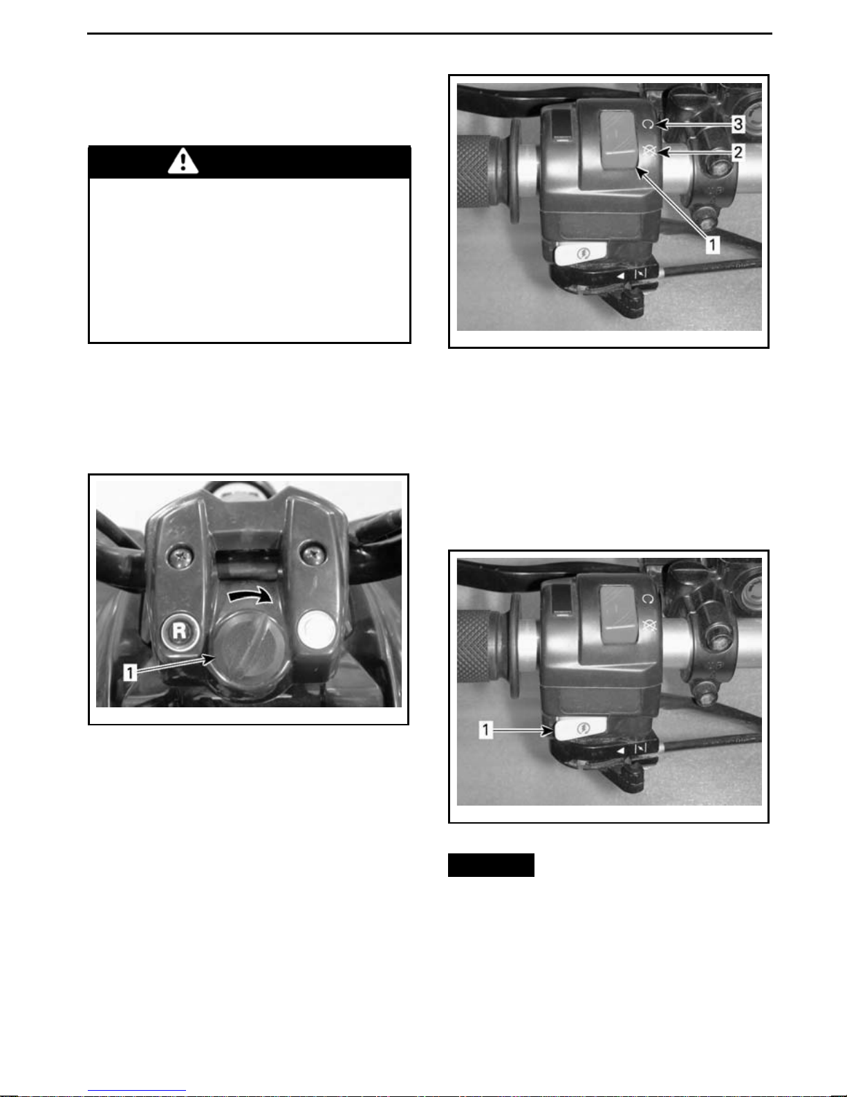
OPERATING INSTRUCTIONS
StartingtheEngine(Basic
Procedure)
WARNING
Always proceed with the pre-ride
inspection as described in the
SAFETY INFORMATION
prior to operating the vehicle. Always check for proper operation
of critical controls, safety features
and mechanical components before starting.
Transmission lever must be set to
NEUTRAL.
section
vmo2009-004-005_b
1. E me rgency engine stop switch
2. STOP position
3. RUN position
Insert key in ignition switch and turn to
ON position.
vmo2008-008-024_a
TYPICAL — TURN TO ON POSITION
1. Ignition key
Set the emergency engine stop switch
to the RUN position.
Refer to
START THE ENGINE
USING THE CHOKE TO
section.
Press and hold LH brake lever.
Press the engine start button and hold
until engine starts.
vmo2009-004-005_c
1. Engine start button
NOTICE
Do not hold start button
more than 10 seconds. A rest period
should be observed between cranking cycles to allow starte r cool down.
Pay attention not to discharge battery.
_______________
73
Page 76
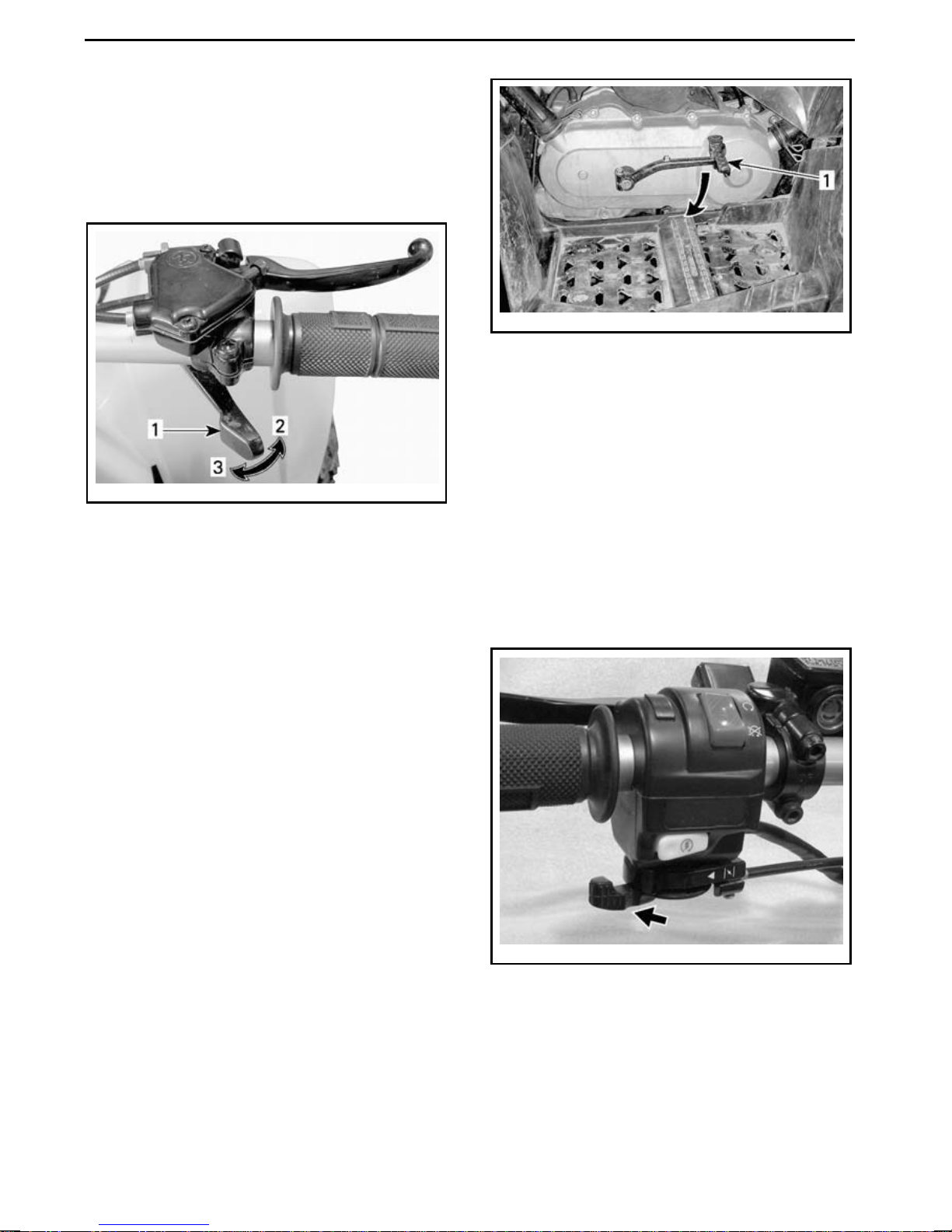
OPERATING INSTRUCTIONS
NOTE: Throttle assist may be used to
help start the engine faster. Press the
throttle lever slightly; if it is pressed too
much, the choke system will not be activated.
vmo2008-020-003_a
TYPICAL
1. Throttle lever
2. To accelerate
3. To decelerate
Release the engine start button immediately after the engine has started and
then release brake.
mmo2008-008-051_a
TYPICAL
1. Kick start pedal
Repeat this procedu re completely if
necessary.
Using the Choke to Sta rt
the E ngine
Cold Weather (Below 0°C (32°F))
In temperatures below 0°C (32°F),
place choke lever in full choke position
(100%).
Emergency Manual Starting
Manual start is provided in the event
electric start does not work.
Follow the starting procedure previously described but instead of using
the electric starter, use the kick s tart
pedal.
To start engine, gently press pedal
down until the kick starter mechanism
engagement is felt, then kick down
with a rapid follow through motion.
vmo2009-004-006_a
FULL CHOKE POSITION
After engine starts, adjust ch
oke lever
until optimal engine RPM is achieved.
NOTE: Overusing the choke may f
lood
the engine and make it hard to start.
Refer to
TROUBLESHOOTING
if this
occurs.
74
______________
Page 77
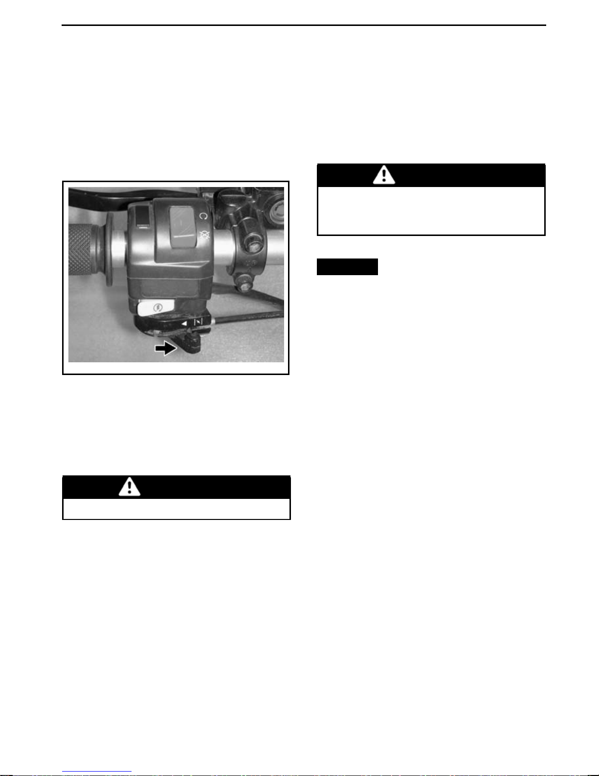
OPERATING INSTRUCTIONS
Cold Weather (Above 0°C (32°F))
In temperatures above 0°C (32°F),
place choke lever at 75% of full choke
position.
After engine starts, leave choke at
75% for 20 seconds and then set
choke lever to off position.
vmo2009-004-005_d
OFF POSITION
Shifting the Transmission
Let engine idle to warm up.
Apply brakes and set the transmission
selector lever to ”F” (forward), or ”R”
(reverse).
Release brakes.
WARNING
Make sure the parking brake is
fully disengaged before operating the vehicle.
NOTICE
ward to reverse, or vice-versa, always c ompletely stop the vehicle
and apply the brake prior to moving
the transmission lever.
NOTE: The engine willstopifanyshift-
ing is done at high RPM.
When changing from for-
Warm Engine Starting
No choke is needed.
Stopping the Engine
WARNING
Avoid parking on a slope.
Release throttle and completely stop
the vehicle.
Apply the parking brake.
Set transmission lever to the FOR-
WARD position.
Set the emergency engine stop switch
to the STOP position.
Turn ignition key to OFF position.
Turn fuel valve to OFF position.
Remove key from ignition switch.
_______________
75
Page 78
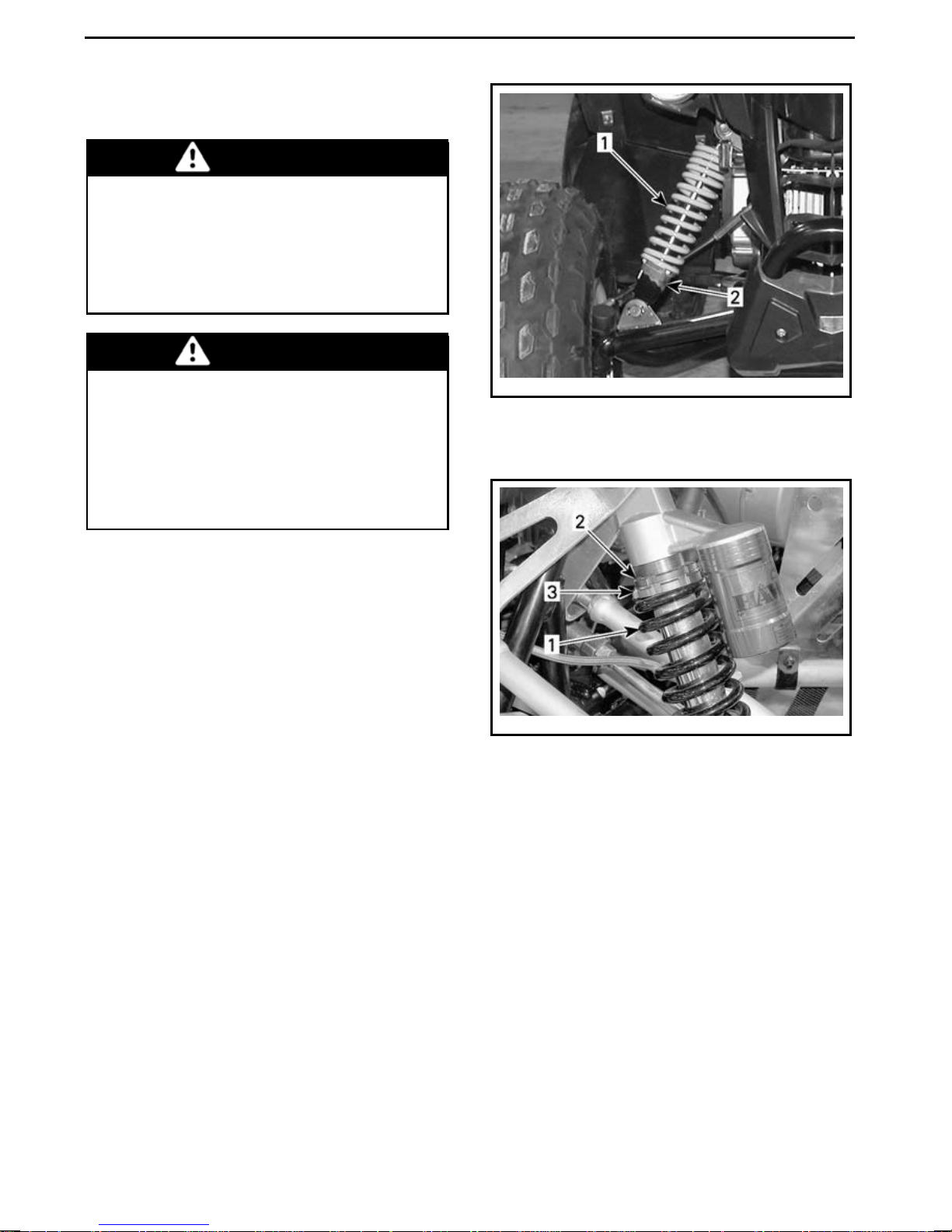
TUNE YOUR RIDE
Suspension Adjustment
WARNING
Suspension adjustment could a ffect vehicle handling. Always take
time to familiarize yourself with
the vehicle's behavior after any
suspension adjustment has been
made.
WARNING
Left and right front shock adjustment must always be set to the
same position. Never adjust one
shock only. Uneven adjustment
can cause poor handling and loss
of stability, which could lead to an
accident.
vmo2008-008-029_a
DS 90 — FRONT SUSPENSION
1. Front spring
2. Turn adjusting cam
Spring Preload Adjustment
Shorten the springs for a firmer ride
and rough road condition.
Lengthen the springs for a softer ride
and smooth road condition.
Adjust by turning adjustment cam or
ring accordingly. Use tool from vehicle
tool kit.
vmo2008-020-010_a
DS 90 X — FRONT SUSPE NSIO N
1. Front spring
2. L oosen locking ring
3. Turn adjustment ring
76
______________
Page 79
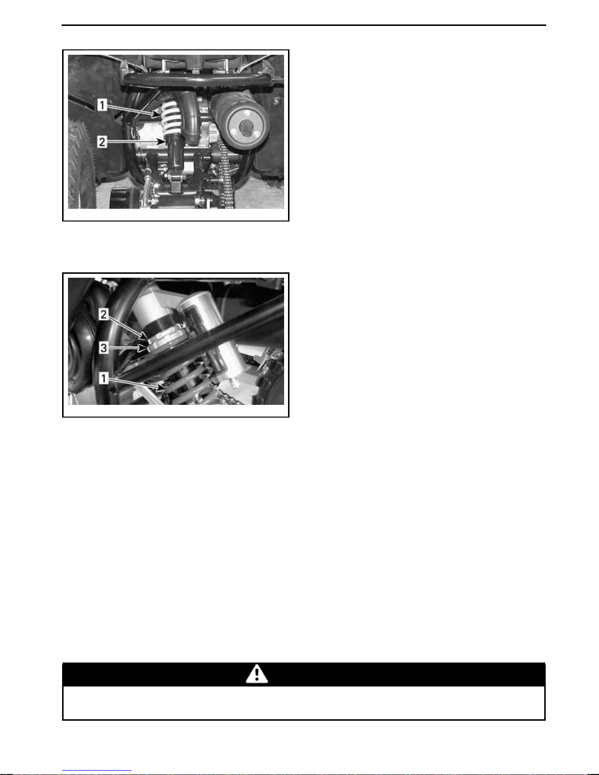
vmo2008-008-030_a
DS 90 — REAR SUSPENSION
1. Rear spring
2. Turn adjusting cam
TUNE YOUR RIDE
vmo2008-020-011_a
DS 90 X — REAR SUSPENSION
1. Rear spring
2. L oosen locking ring
3. Turn adjustment ring
While reading this Operator’s Guide, remember that:
WARNING
Indicates a potential hazard that, if not avoided, could result in serious
injury or death.
_______________
77
Page 80
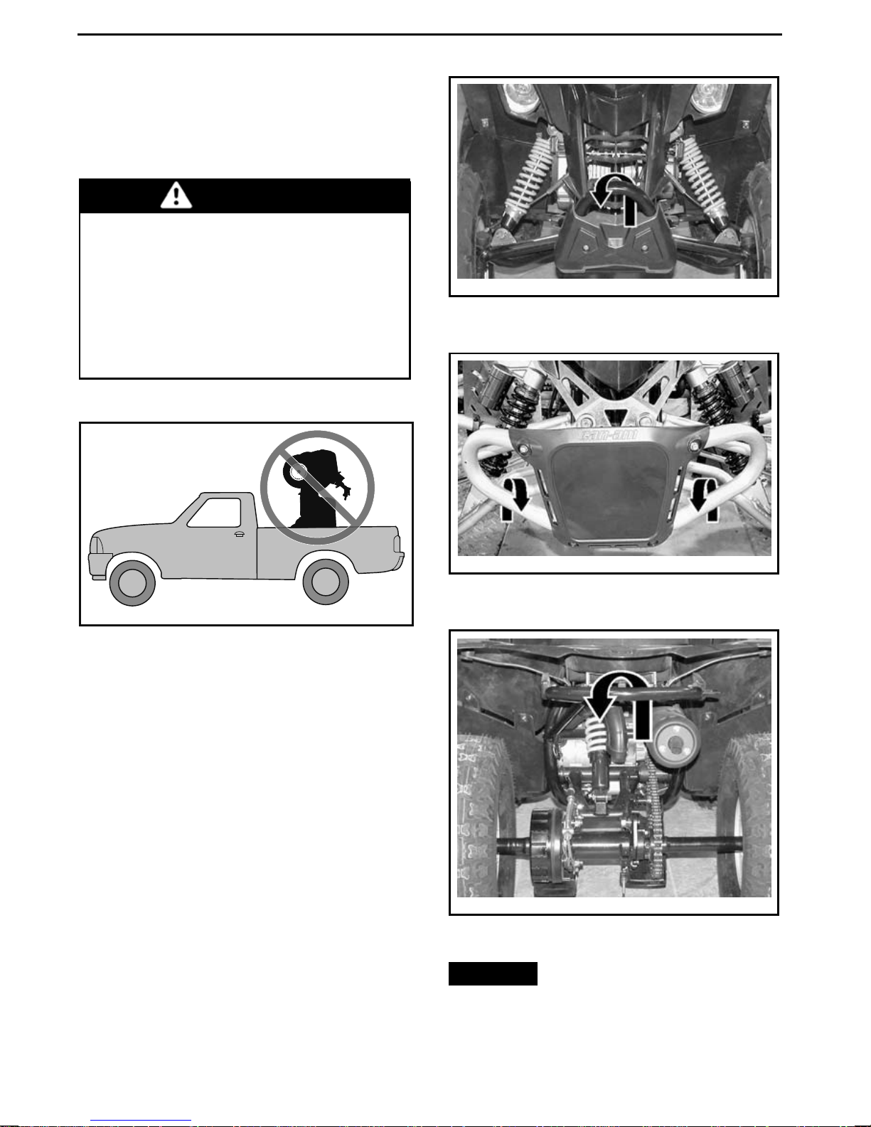
VEHICLE TRANSPORTATION
When transporting this vehicle, secure
it to a trailer using suita ble tie-downs.
Use of ordinary ropes is not recommended.
WARNING
Do not tow this vehicle behind a
car or other vehicle. Use a trailer.
Never tip this vehicle on end for
transporting. The vehicle must be
in its normal operating position
(on all four wheels) facing towards
the front of the transporting vehicle.
vmo2008-008-025_a
DS 90 — FRONT TIE-DOWN POINT
LOCATION
V00A17Y
Remember to:
– Set the fuel valve to the O FF posi-
tion.
– Apply the parking brake.
– Secure the front of the vehicle by
the front bumper, and the rear of the
vehicle by the rear bumper.
vmo2008-020-012_a
DS 90 X — FRONT TIE-DOWN POINT
LOCATION
vmo2008-008-026_a
ALL MODELS — REAR TIE-DO WN POINT
LOCATION
78
______________
NOTICE
Securing vehicle at other
locations may damage the vehicle.
Page 81

MAINTENANCE
_______________
79
Page 82

BREAK-IN INSPECTION
BRP suggests that after the first 5 hours or 100 km (62 mi) of operation, whichever
comes first, your vehicle be inspected by an authorized Can-Am dealer. The
break-in inspection is very important and must not be neglected.
NOTE: The break-in inspection is at the expense of the vehicle owner.
We recommend that this inspection be signed by an authorized Can-Am dealer.
Date of inspection Authorized de aler sig nature
Dealer name
80
______________
Page 83
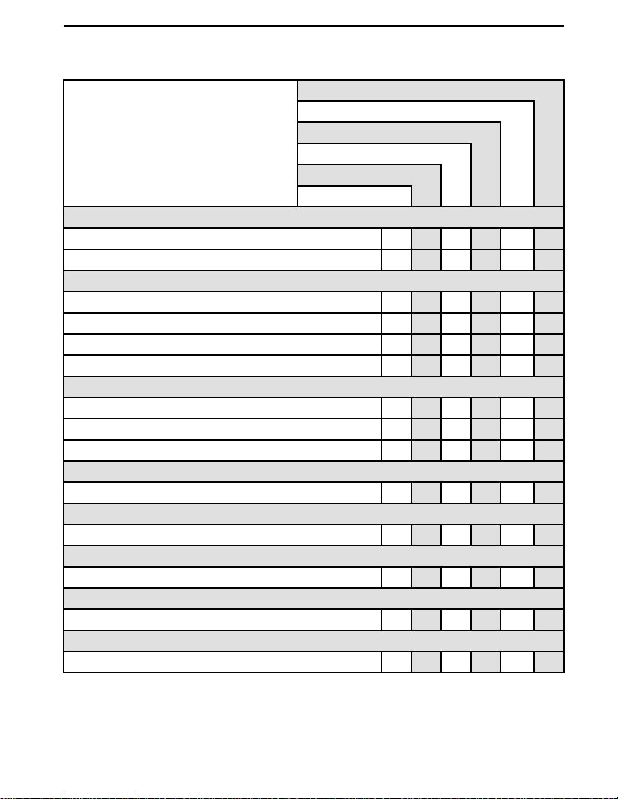
Break-In Inspection Chart
BREAK-IN INSPECTION CHART
ENGINE
BREAK-IN INSPECTION
REPLACE
ADJUST
TIGHTEN
LUBRICATE
CLEAN
INSPECT
Engine oil
Valve clearance XX
FUEL SYSTEM
Fuel lines and connections X
Throttle cable/housing
Carburetor X
Idle speed
ELECTRICAL SYSTEM
Spark plug
Battery
Battery voltage
CVT TRANSMISSION
CVT air inlet/outlet ducts X
GEARBOX
XX
X
XX
X
X
X
Gearbox oil X
WHEEL/TIRES
Wheel nuts/studs X
STEERING SYSTEM
Handlebar fasteners X
BRAKES
Brake system
X
_______________
81
Page 84
MAINTENANCE SCHEDULE
Maintenance is veryimportantforkeeping your vehicle in safe operating condition.
Proper maintenance is the owner's respo n sibility. The vehicle should be se rviced
as per maintenance schedule.
The maintenance schedule does not exempt the pre-ride inspection.
WARNING
Failure to properly maintain the vehicle according to the maintenance
schedule and procedures can make it unsafe to operate.
MAINTENANCE SCHEDULE
WEEKLY
A: Adjust
C: Clean
I: Inspect
L: Lubricate
R: Replace
PART/TASK LEGEND
ENGINE
Engine oil R
Engine oil strainer C Customer
Air filter I, C
Air injection valve filter I, C
Valve clearance A Dealer
Crankcase breather
system
(1)
(1)
MONTHLY
ONCEAYEAROREVERY100HOURS
(3)
(1)
R
(1)
R
(2)
I
EVERY 2 YEARS OR 200 HOURS
TO BE PERFOR MED BY
Customer
Customer
Customer
Dealer
(1) More often under dusty
conditions. Refer to
in
MAINTENANCE PROCEDURES
(2) Inspect every 6 months.
(3) Replace every 3 months or
40 hours.
AIR FILTER
.
Spark arrester C Customer
Exhaust system I Dealer
82
______________
Page 85
MAINTENANCE SCHEDULE
WEEKLY
MAINTENANCE SCHEDULE
A: Adjust
MONTHLY
C: Clean
I: Inspect
L: Lubricate
ONCEAYEAROREVERY100HOURS
EVERY 2 YEARS OR 200 HOURS
R: Replace
TO BE PERFOR MED BY
PART/TASK LEGEND
FUEL SYSTEM
Fuel lines and
connections
I Dealer
Fuel filter R Dealer
(4) Inspect, clean and adjust every
6months.
Throttle cable/housing I, A L
Carburetor I, C
Idle speed I
(4)
(4)
Dealer/
Customer
Dealer
Dealer
ELECTRICAL SYSTEM
Spark plug R Dealer
Battery I
Dealer/
Customer
DRIVE SYSTEM
Drive chain and
Sprockets
(5)
I
Dealer
WHEELS/TIRES
Wheel bearings I Customer
Wheel bolts I Customer
TRANSMISSION
(CVT)
Drive belt I Dealer
Drive and driven pulleys I, C, L Dealer
CVT air inlet/outlet ducts I, C Customer
—
(5) More often under severe use such
as dusty area, sand, snow, wet or
muddy conditions.
—
—
_______________
83
Page 86

MAINTENANCE SCHEDULE
MAINTENANCE SCHEDULE
WEEKLY
A: Adjust
MONTHLY
C: Clean
I: Inspect
L: Lubricate
ONCEAYEAROREVERY100HOURS
EVERY 2 YEARS OR 200 HOURS
R: Replace
TO BE PERFOR MED BY
PART/TASK LEGEND
GEARBOX
Gearbox oil R Dealer
STEERING SYSTEM
Handlebar fasteners I Dealer
Steering knuckles
(DS 90)
(6)
L
Customer
(6) Lubricate every 6 months.
Steering shaft L Dealer
Steering system I Dealer
—
SUSPENSION
Suspension system I Customer
BRAKES
Brake fluid (DS 90 X)
Brake system
I, A
(7) (8)
Brake pads/shoe I
(7)
(7)
R
Dealer/
Customer
Dealer
Customer
Dealer
—
(7) Brake fluid replacement
or any brake system repairs
must be performed by an
authorized Can-Am dealer.
(8) Hydraulic brakes are self-adjusting
and require no adjustment.
84
______________
Page 87
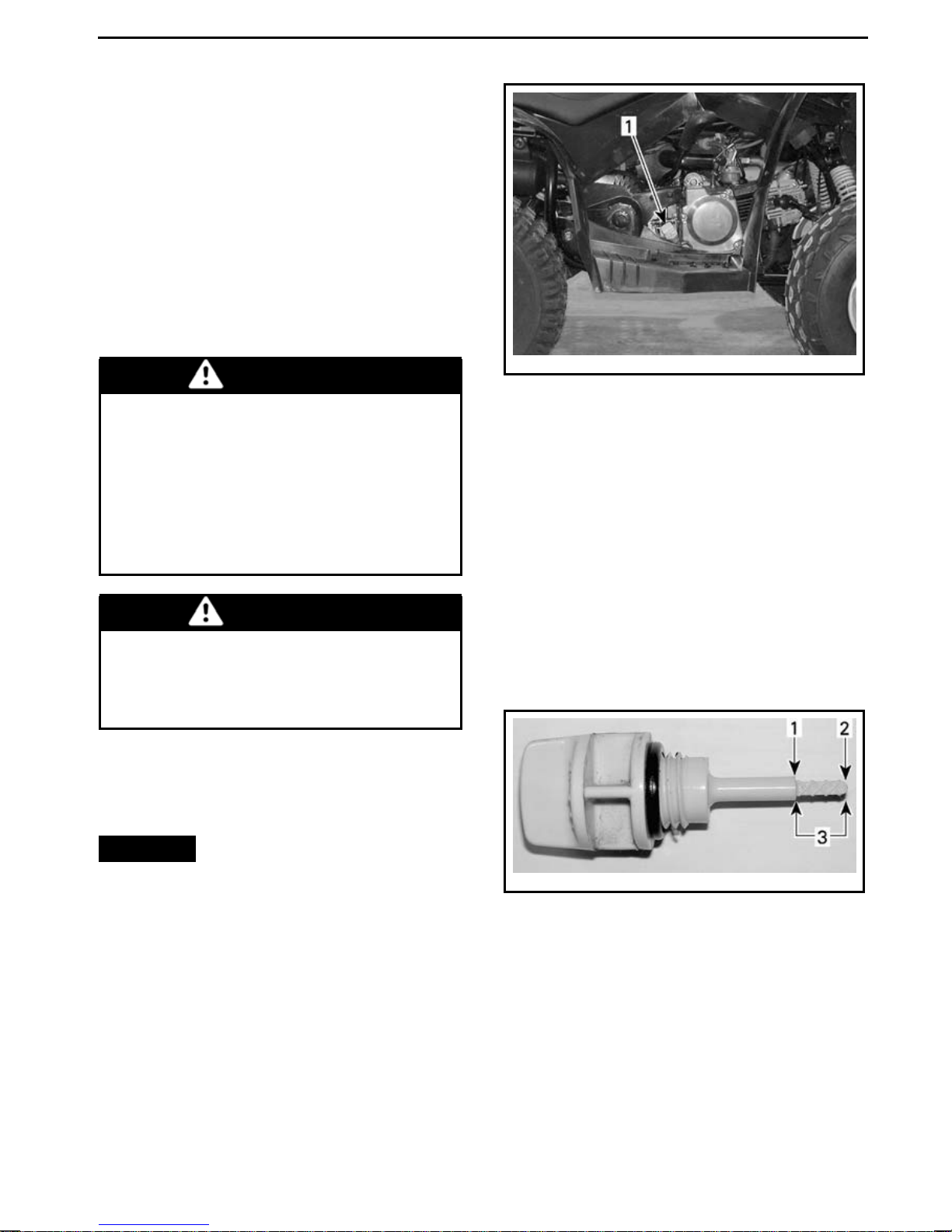
MAINTENANCE PROCEDURES
This section includes instructions for
basic maintenance procedures. If you
have the necessary mechanical s kills
and the required tools, you can perform these procedures. If not, see
your authorized Can-Am dealer.
Other important items in the maintenance schedule that are more difficult
and require special tools are best performed by your authorized Can-Am
dealer.
vmo2008-008-021_a
WARNING
Turn off the engine and follow
these maintenance procedures
when performing maintenance.
If you do not follow proper maintenance procedures you can be
injured by hot parts, moving parts,
electricity, chemicals or other hazards.
WARNING
Should removal of a locking device be required (e.g. lock tab,
self-locking fastener, etc.), always
replace it with a new one.
TYPICAL — RH SIDE OF ENGINE
1. Dipstick
With vehicle on a level surface, start
engine and let it run for several minutes, then stop engine and check the
oil level as follows:
1. Unscrew dipstick, remove it and
2. Reinstall dipstick and screw it in
3. Remove dipstick and check oil
wipe it clean.
completely.
level. It should be near or e qual
to the upper mark.
Engine Oil
Engine Oil Level
NOTICE
and adjust as necessary. Do not
overfill. Operating the engine with
an improper level may severely
damage engine. Wipe off any
spillage.
NOTE: While ch ecking th e oil level, vi-
sually inspect engine area for leaks.
Check level frequently
vmo2008-020-007_a
1. Full
2. Add
3. O perating range
To add oil, remove dipsti
funnel in the dipstick hole to avoid
spillage.
Add a small amount of oil and recheck
oil level.
Repeat until oil level reaches the dipstick’s upper mark. Do not overfill.
ck. Place a
_______________
85
Page 88
MAINTENANCE PROCEDURES
Completely tighten dipstick.
Recommended Engine Oil
For the summer season, use XPS
4-STROKE SYNTH. BLEND OIL (SUMMER) (P/N 293 600 121).
For the winter season, use XPS
4-STROKE SYNTHETIC OIL (ALL CLIMATE) (P/N 293 600 112).
NOTE: The XPS oil is specially formulated and tested for the severe requirements of this engine.
If not available, use 4-stroke SAE
5W30 engineoilthat meets or exceeds
the requirements for API service classification SM, SL or SJ. Always check
the API service label on the oil container, it must contain at least one of
the above standards. Refer to the viscosity chart for details.
Engine Oil Viscosity Chart
SAE 0W30
SAE 5W30
SAE 10W30
SAE 10W40
SAE 15W40
SAE 20W50
Temp erature Range
50°C (122°F)
40°C (104°F)
30°C (86°F)
20°C (68°F)
10°C (50°F)
0°C (32°F)
-10°C (14°F)
-20°C (-4°F)
-30°C (-22°F)
Engine Oil Change
The oil change should be carried out on
a warm engine.
CAUTION Engine oil can be
very hot. In order to avoid potential burns, do not remove the engine
drain plug if the engine is hot. Wait
until the engine oil is warm. Always
wear appropriate skin and eye protection. Chemicals can cause skin
rash and e ye injury.
86
______________
Ensure vehicle is on a level surface.
Page 89
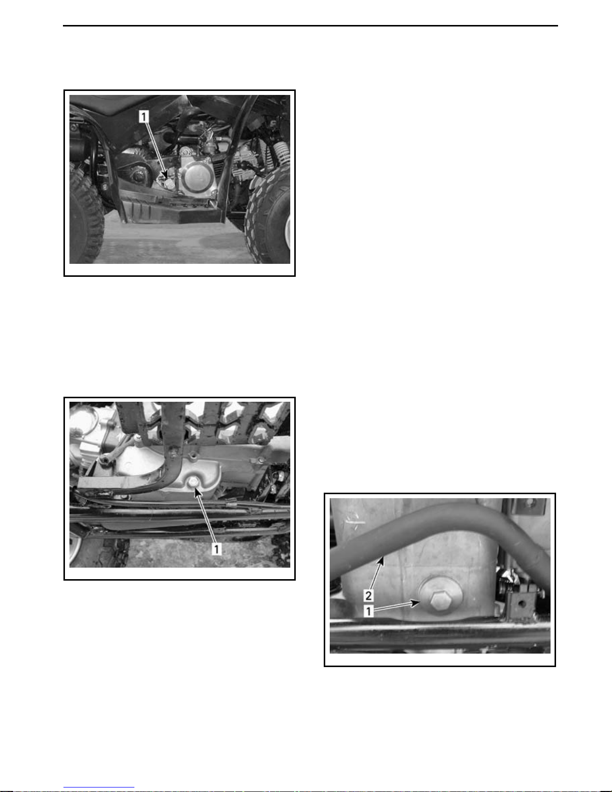
MAINTENANCE PROCEDURES
Remove dipstick.
vmo2008-008-021_a
TYPICAL — RH SIDE OF ENGINE
1. Dipstick
Clean the drain plug area.
Place a drain pan under the engine
drain plug area.
Unscrew drain plug.
Install and torque strainer cover to
42 N•m ± 4 N•m (31 lbf•ft ± 3lbf•ft).
Clean drain plug washer and check it's
condition, replace it if necessary.
Clean engine and drain plug contact
surfaces, then reinstall drain plug
and torque it to 22.0 N•m ± 2.2 N•m
(16lbf•ft ±2lbf•ft).
Refill engine with the specified quantity of recommended engine oil. Refer
to
SPECIFICATIONS
for capacity.
Start engine and let idle for a few minutes. Ensure oil strainer and drain plug
areas are not leaking.
Stop engine. Wait a few minutes to
allow the oil to flow down into the
crankcase, then recheck oil level. Adjust oil level if necessary.
Dispose of theusedoilasperyourlocal
environmental regulations.
vmo2008-008-044_a
LH SIDE OF ENGINE
1. Drain plug
Allow sufficient time for all the oil to
flow out of the engine.
Clean oil strainer, refer to
STRAINER
in this subsection.
OIL
Wipe off any oil s pillage on engine.
Reinstall oil strainer, spring, and O-ring.
Oil Strainer
Oil Strainer Cleaning
Remove oil strainer and spring for
cleaning (if necessary), refer to
TENANCE SCHEDULE
vmo2008-008-045_a
UNDERNEATH ENGIN E
1. Oil strainer cover
2. Exhaust pipe
for details.
MAIN-
_______________
87
Page 90
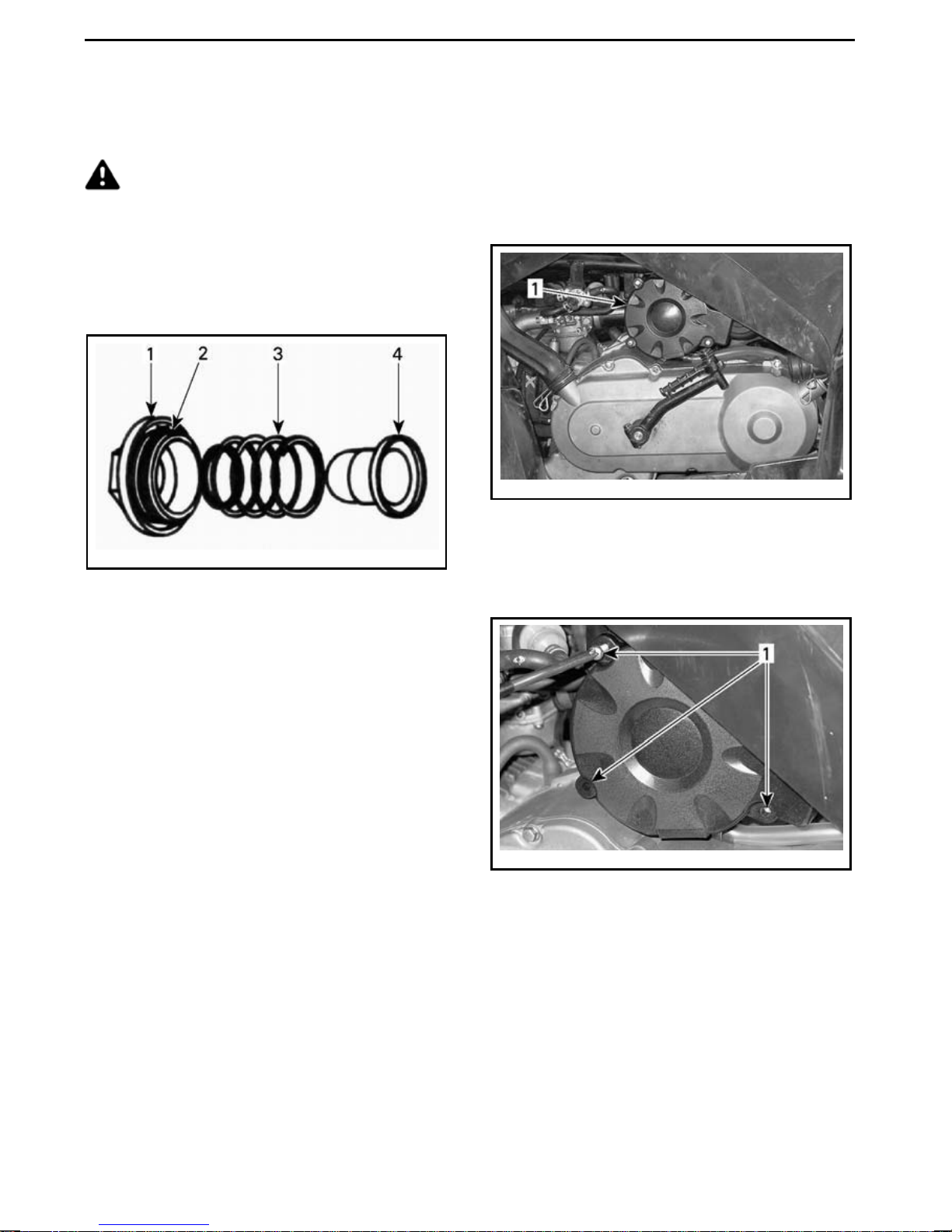
MAINTENANCE PROCEDURES
To c lean oil strainer,use a s olvent, then
dry us ing compressed air.
CAUTION Always wear ap-
propriate skin and eye protection.
Chemicals can cause skin rash and
eye injury.
NOTE: Check cover O-ringand replace
it if necessary.
NOTE: Riding in a group in these conditions increases even more the air
filter maintenance and replacement
requirement.
AirFilterLocation
vmo2008-008-036_a
1. Air filter
vmo2006-014-037_a
TYPICAL
1. Cover
2. O-ring
3. Spring
4. S trainer
Air F ilter
Air Filter Maintenance Guideline
As with any ATV, air filter maintenance
is critical to ensure proper engine performance and life span.
Air filter maintenance should be adjusted according to riding conditions.
Air filter maintenance must be increased in frequency for the following
dusty conditions:
– Riding on dry sand
– Ridingondrydirtcoveredsurfaces
– Riding on dry gravel roads or similar
conditions.
AirFilterRemoval
Remove air filter box cover.
mmo2008-008-053_a
1. Screws
Remove air filter from housing.
88
______________
Page 91
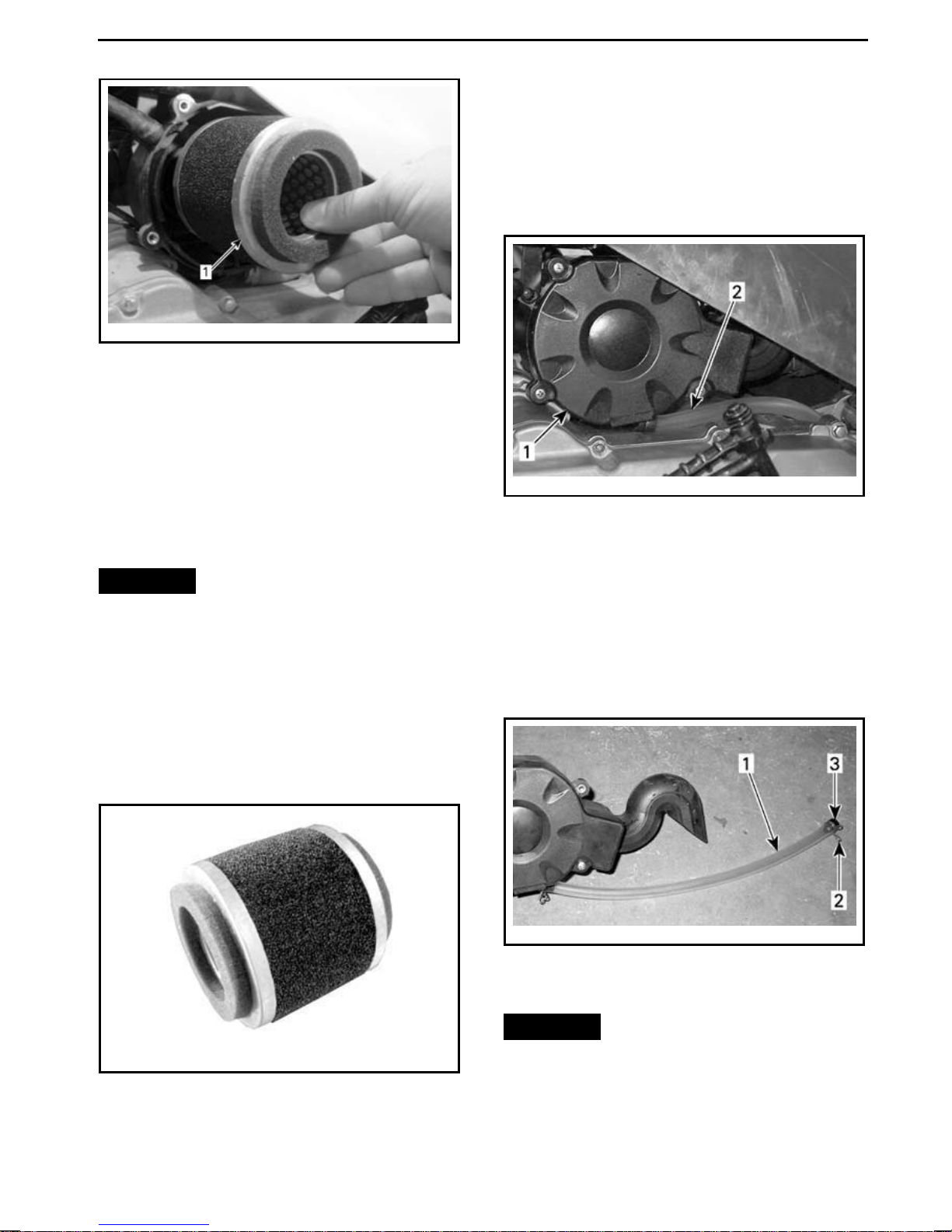
vmo2015-004-502_a
1. Air filter
Air Fi lte r Maintenance and
Replacement
For light maintenance on air filter, compressedaircanbeusedtoremovedust
from air filter.
For any other condition, replace air filter.
NOTICE
Engine performance
degradation or severe damage can
occur if the air filter is not properly
maintained and/or replaced.
Air Filter Installation
MAINTENANCE PROCEDURES
Air Filter Housing
Air Filter Housing Draining
Periodically insp ec t air filter housing
drain tube for liquids or deposits.
mmo2008-008-057_a
1. Air filter housing
2. D rain tube
NOTE: If vehicle is usedindustyarea s,
inspect more frequently than specified
in
MAINTENANCE SCHEDULE
If liquids/deposits are found, squeeze
and remove the clamp. Pull drain tube
plug out and empty tube.
.
Installation is the reverse of removal
procedure. Pay attention to ensure
proper filter positioning in housing.
vmo2015-004-503
mmo2008-008-061_a
1. D rain tube
2. Clamp
3. Plug
NOTICE
Do not start engine when
liquids/deposits are found in the
drain tube.
_______________
89
Page 92
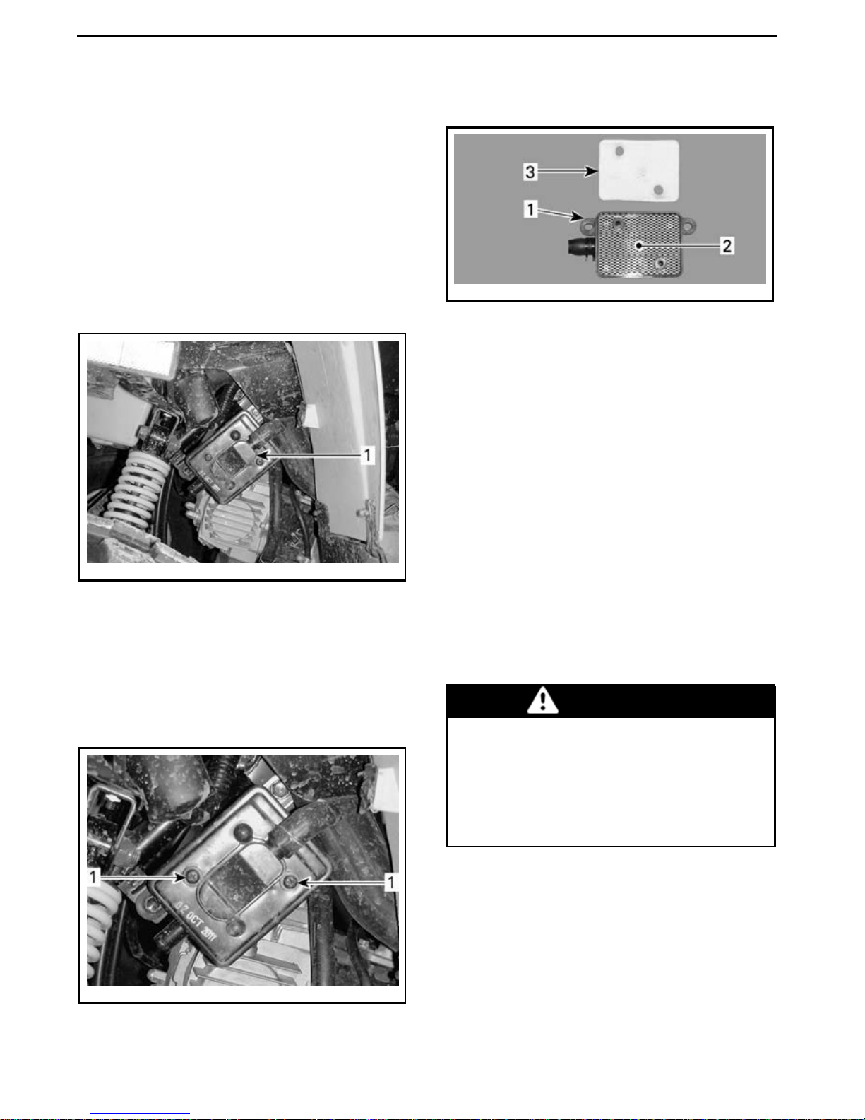
MAINTENANCE PROCEDURES
When liquids or deposits are found, air
filter and housing must be ins pected,
dried or replaced depending on its condition.
Air Injection Valve
Air Injection Valve Location
Air injection valve is located on the LH
side of the vehicle underneath front
fender.
Remove filter from air injection valve.
vmo2013-004-009_a
TYPICAL
1. Air injection valve
2. Screen
3. Air filter
Clean air filter and inside of air injection
valve using pressurized air.
NOTE: If the air filter is still dirty, replace it with a new one.
When finished, properly reinstall removed parts in the reverse order of
their removal.
vmo2013-004-007_A
1. Air injection valve
Air Injection Valve Cleaning
NOTE: Clean cover before removing.
Remove cover retaining screws.
Remove air injection valve cover.
Spark Arrester
Spark Arrester Cleaning
The muffler must be p eriodically
purged of accumulated carbon.
WARNING
Never perform this operation immediately after the engine has
been run because exhaust system
is very hot. Wear eye protection
and gloves. Respect all applicable
laws and regulations.
Remove muffler cover (if ap plic able).
vmo2013-004-008_a
1. Remove screws
90
______________
Page 93
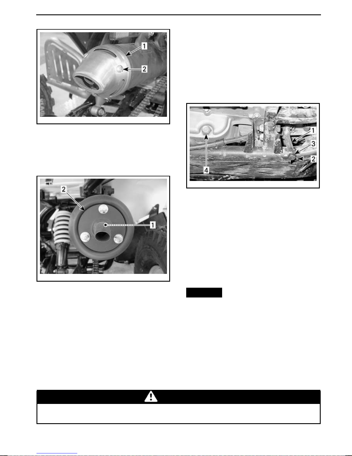
vmo2008-020-013_a
DS 90 X
1. M uffler cover
2. Remove screws
Remove th e spark a rrester from the
muffler.
MAINTENANCE PROCEDURES
CVT Cover
CVT Cover Draining
Whenever you suspect that water has
entered the CVT cover, drain the CVT
housing by removing the drain tube
plug.
mmo2008-008-060_a
LH SIDE OF VEHICLE
1. D rain tube
2. Clamp
3. Plug
4. E ngine drain plug
Gearbox Oil
Recommended Gearbox Oil
Use 165 ml (6 U.S. oz) of XPS CHAINCASE OIL (P/N 415 129 500) or an
vmo2008-008-041_a
1. Spark arrester
2. M uffler tip
Remove carbon deposits from the
spark arrester using a brush.
NOTE: Use a soft brush and be careful
to avoid damaging spark arrester.
Reinstall the spark arrester in muffler.
equivalent SAE 75W90 chaincase oil).
NOTICE
oil when servicing the gearbox.
Gearbox Oil Level
There is no dipstick provided with this
vehicle, the gear box oil level cannot be
checked.
Reinstall muffler cover (if applicable).
While reading this Operator’s Guide, remember that:
WARNING
Do not use other types of
Indicates a potential hazard that, if not avoided, could result in serious
injury or death.
_______________
91
Page 94
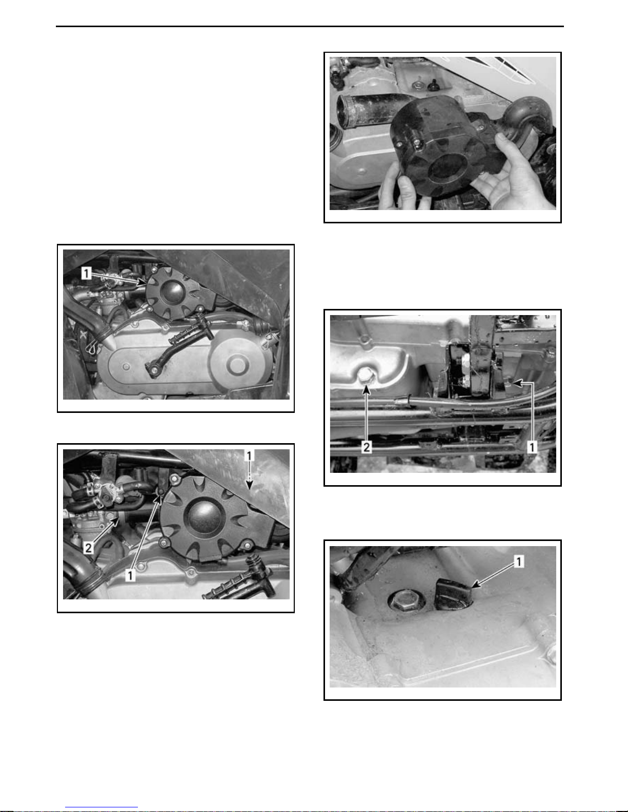
MAINTENANCE PROCEDURES
The only way to ensure the level is correct is to drain the gearbox and refill
it with the sp ecified quantity of the
recommended gearbox oil. Refer to
GEARBOX OIL CHANGE
for proce-
dure.
Gearbox Oil Change
Place the vehicle on a level surface.
Remove the air filter housing from the
vehicle.
vmo2008-008-036_a
1. Air filter housing
vmo2008-008-062_a
REMOVE A IR FILTER HOUSING
Clean gearbox drain plug and oil filler
plug area, then remove the gearbox
drainplugandwasher.
mmo2008-008-056_a
DRAIN PLUG — LH SIDE OF ENGINE
1. G earbox drain plug
2. E ngine oil drain plug
vmo2008-008-058_a
1. Remove screws
2. L oosen clamp
92
______________
mmo2008-008-059_a
FILL PLUG — L H SIDE OF ENGINE
1. G earbox oil filler plug
Page 95
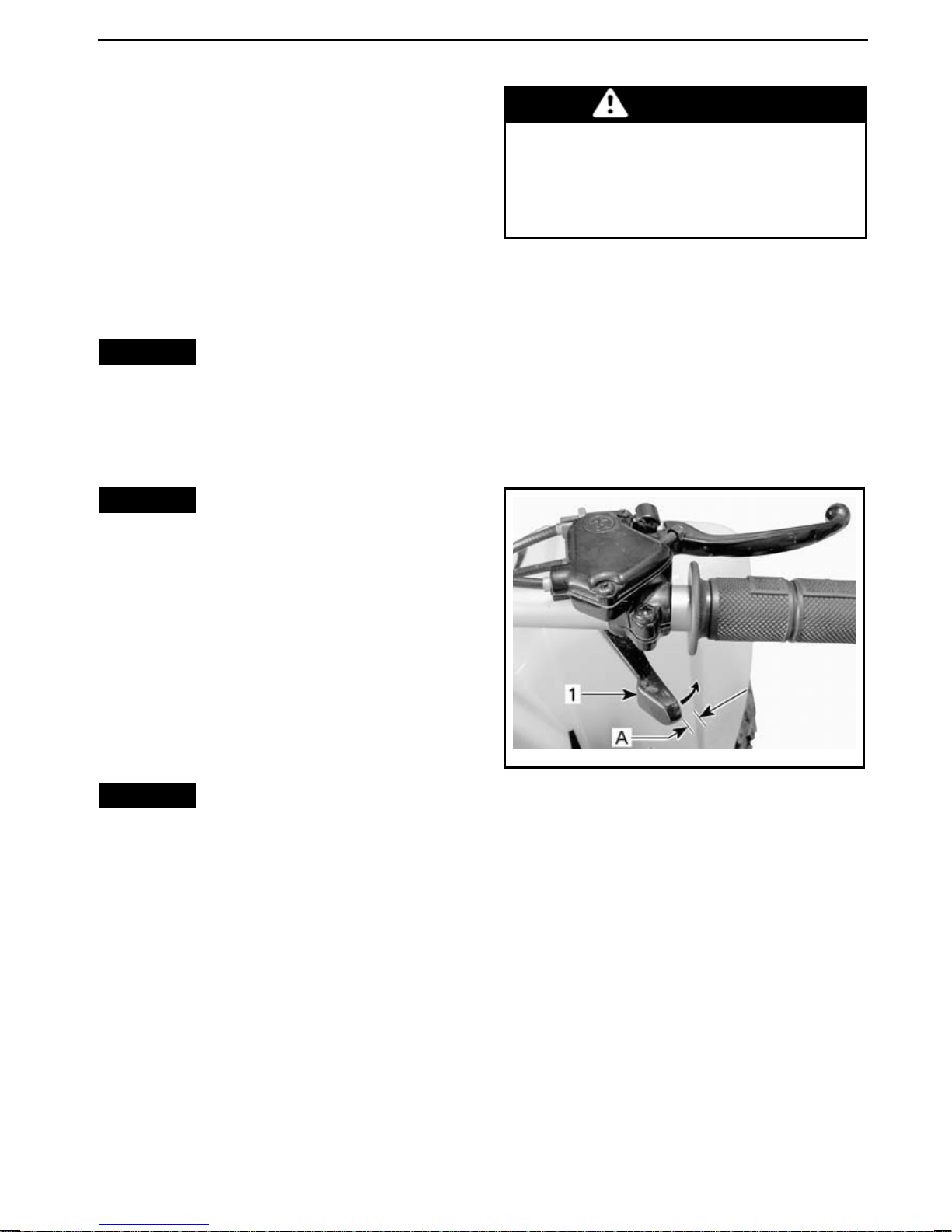
MAINTENANCE PROCEDURES
Allow enough time for oil to flow out of
gearbox.
Reinstall d rain plug and washer
and torque to 16.0 N•m ± 1.6 N•m
(142 lbf•in ±14lbf•in).
Remove gearbox oil filler plug and refill gearbox using 165ml (6U.S. oz) of
XPS CHAINCA SE OIL (P /N 415 12 9
500) or an equivalent SAE 75W90
chaincase oil.
NOTICE
vided with this vehicle to check gearbox oil level. Be sure gearbox is
completely drained before replenishing it with the specified amount
of recommended oil.
NOTICE
oil when servicing the gearbox.
There is no dipstick pro-
Do not use other types of
WARNING
Always use a silicone-based lubricant. Using another lubricant
(such as a water-based lubricant)
could cause the throttle lever/cable to stick or become stiff.
Throttle Cable Adjustment
Check throttle lever free-play, adjust if
necessary.
NOTE: If correct adjustment is
unattainable, see an authorized
Can-Am dealer.
The norm al throttle free-play is
5 mm to 10 mm (.197in to .394in).
Reinstall oil filler plug.
Reinstall all o t her removed parts.
Throttle C able
Throttle Cable Inspection
Inspect throttle cable for excessive
wear, kinking or fraying. Ensure cable
moves freely.
NOTICE
replaced if any signs of wear, fraying
or other damages are found.
Throttle Cable Lubrication
Lubricate cable using CABLE LUBRICANT (P/N 293 600 041) or an equivalent silicone cable lubricant to reduce
premature wear and to ensure proper
movement of the cable.
The throttle cable must be
vmo2008-020-003_b
TYPICAL — NORMAL FREE-PLAY
1. Throttle lever
A. 5 mm to 10 mm (.197 in to .394 in)
To adjust cable, slide rubber protector
back to expose throttle cable adjust
er.
_______________
93
Page 96
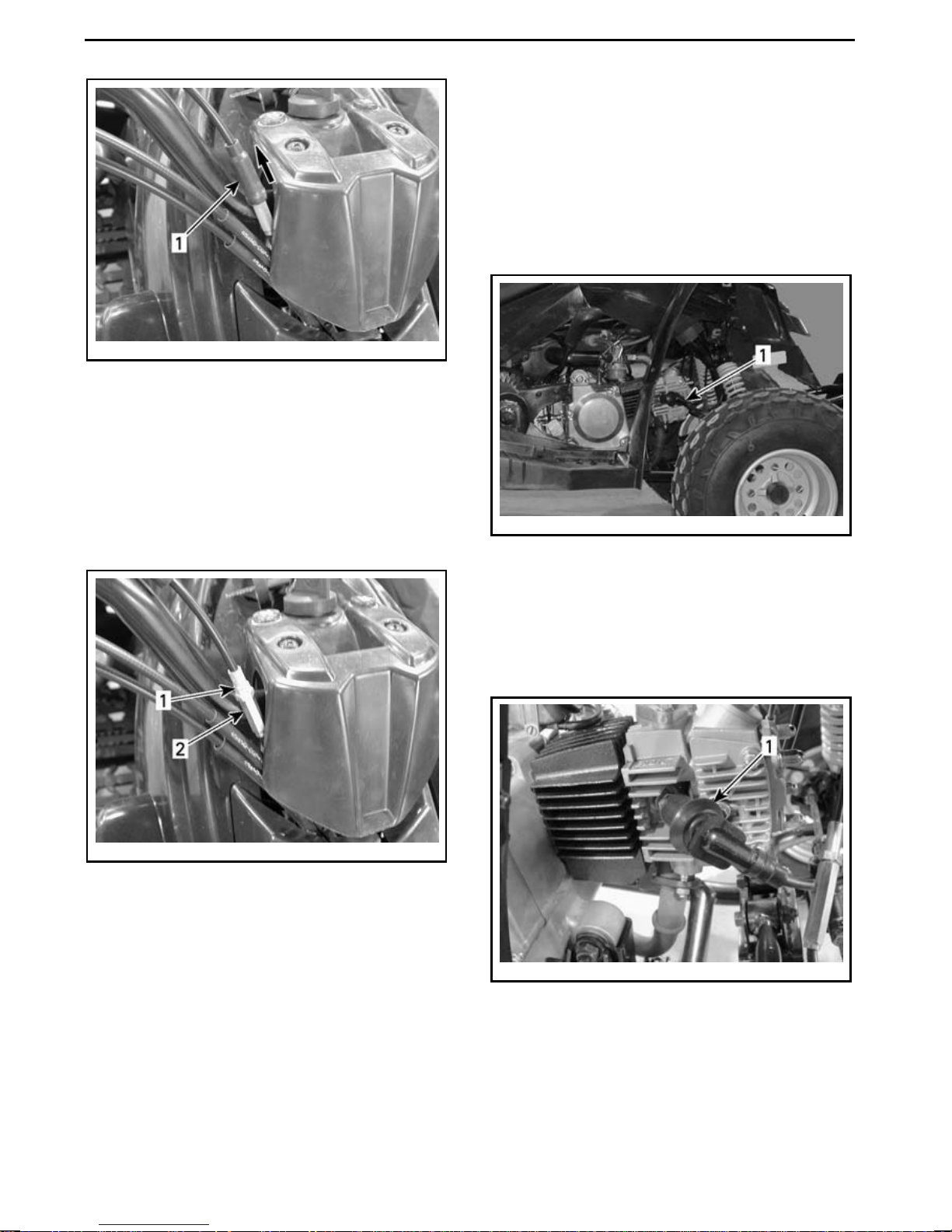
MAINTENANCE PROCEDURES
vmo2008-008-028_a
1. Rubber protector
Loosen lock nut and turn the adjuster
to obtain proper adjustment.
NOTE: Measurethrottlefreeplayat
the tip of throttle lever.
cable is properly routed and not binding on anything when the handlebar is
turned.
Spark P lug
Spark Plug Location
Tighten locking nut and reinstallprotector.
vmo2008-008-027_a
1. Lock nut
2. Adjuster
With the transmission lever set to
NEUTRAL position, start the
engine.
Check if the throttle c a ble is adjus ted
correctly by turning hand
lebar fully to
theright,thenfullytotheleft. Ifthe
engine RPM increases, readjust the
throttle lever free pla
y Ensure throttle
vmo2008-008-033_a
TYPICAL — RH SIDE OF VEHICLE
1. Spark plug
Spark Plug Removal
Disconnect spark plug cable from
spark plug.
vmo2008-008-034_a
1. Spark plug cable
Unscrew spark plug one turn
.
94
______________
Page 97
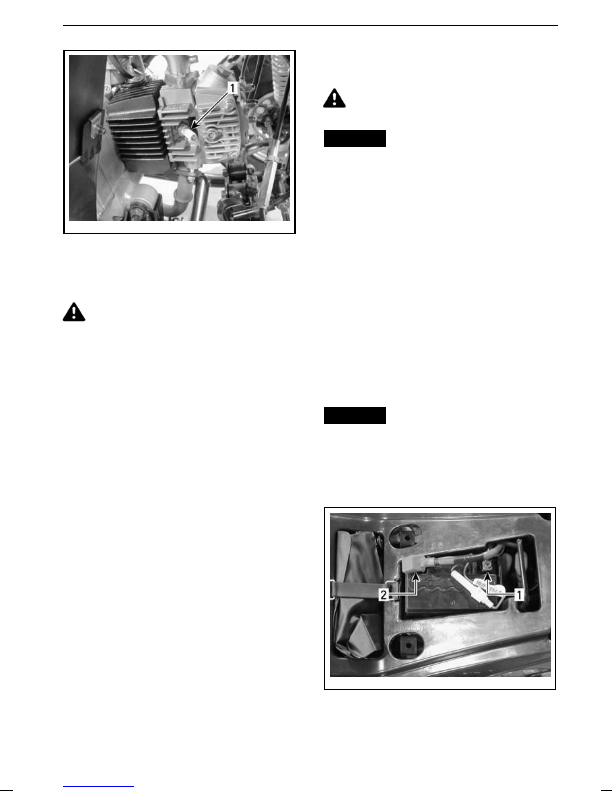
MAINTENANCE PROCEDURES
Battery Maintenance
CAUTION Never charge a bat-
tery while installed in vehicle.
vmo2008-008-035_a
1. Spark plug
If possible, clean spark plug and cylinder head with pressurized air.
CAUTION Always wear safety
goggles when using pressurized air.
Unscrew and remove spark plug completely.
Spark Plug Installation
Priortoinstallation,makesurethecontact surface of the cylinder head and
spark plug is free of grime.
Using a feeler gauge, set the spark
plug gap between 0.7 mm to 0.8 mm
(.028 in to .031in).
NOTICE
Never remove the battery
sealing cap.
These vehicles are equipped with a
VRLA battery (Valve Regulated Lead
Acid). It is a maintenance-free type
battery, there is no need to add water
to adjust electrolyte level.
Clean battery post with a wire b rush.
Apply dielectric grease on post to protect against oxidation.
Battery Inspection
Inspect battery connections for tightness and cleanliness.
Inspect battery support.
Battery Removal
NOTICE
Always respect this order
for disassembly; disconnect BLACK
(-) cable first.
Disconnect BLACK (-) cable first, then
RED (+) cable.
Apply antiseize lubricant over spark
plug threads to prevent a possible
seizure.
Screw spark plug into cylinder head by
hand and tighten with a torque wrench
and proper socket.
Torque spark plug to
11.0 N•m ± 1.1 N•m
(97 lbf•in ±10lbf•in).
Battery
To access thebattery, remove theseat.
vmo2008-008-017_b
1. BLACK (-)
2. RED (+)
_______________
95
Page 98
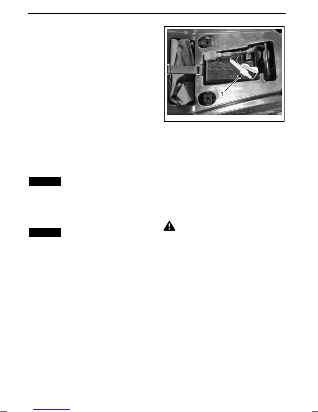
MAINTENANCE PROCEDURES
Remove battery from vehicle.
Battery Cleaning
Clean battery, battery casing, cables
and battery posts using a solution of
baking soda and water.
Remove corrosion from battery c able
terminals and battery posts using a
firm wire brush. Battery top should
be cleaned using a soft brush and any
grease-cutting soap or baking soda solution.
Apply DIELECTRIC GREASE (P/N 293
550 004) or an equivalent on battery
posts to protect against oxidation.
Battery Installation
vmo2008-008-017_a
1. Fuse holder
To replace t he fuse, slightly press the
2 halves of the fuse holder together as
you twist them in a counterclockwise
direction.
Reinstall battery in vehicle.
NOTICE
cable first, then the BLACK (-) cable.
Always reconnect RED (+)
Fuse
Fuse Replacement
NOTICE
fuse as this can cause severe electrical system component damage.
The electrical system is protected by a
single 15 amp fuse.
If the fuse is open circuit (or burnt), replaceitwithafuseofthesamerating.
An in-line fuse hold er is located on the
RED (+) battery cable.
Do not use a higher rated
Lights
Daytime Running Light Bulb
Replacement
DS 90
CAUTION Always turn the ignition switch to the OFF position
before replacing a defective bulb.
Always check light operation after replacement.
96
______________
Page 99
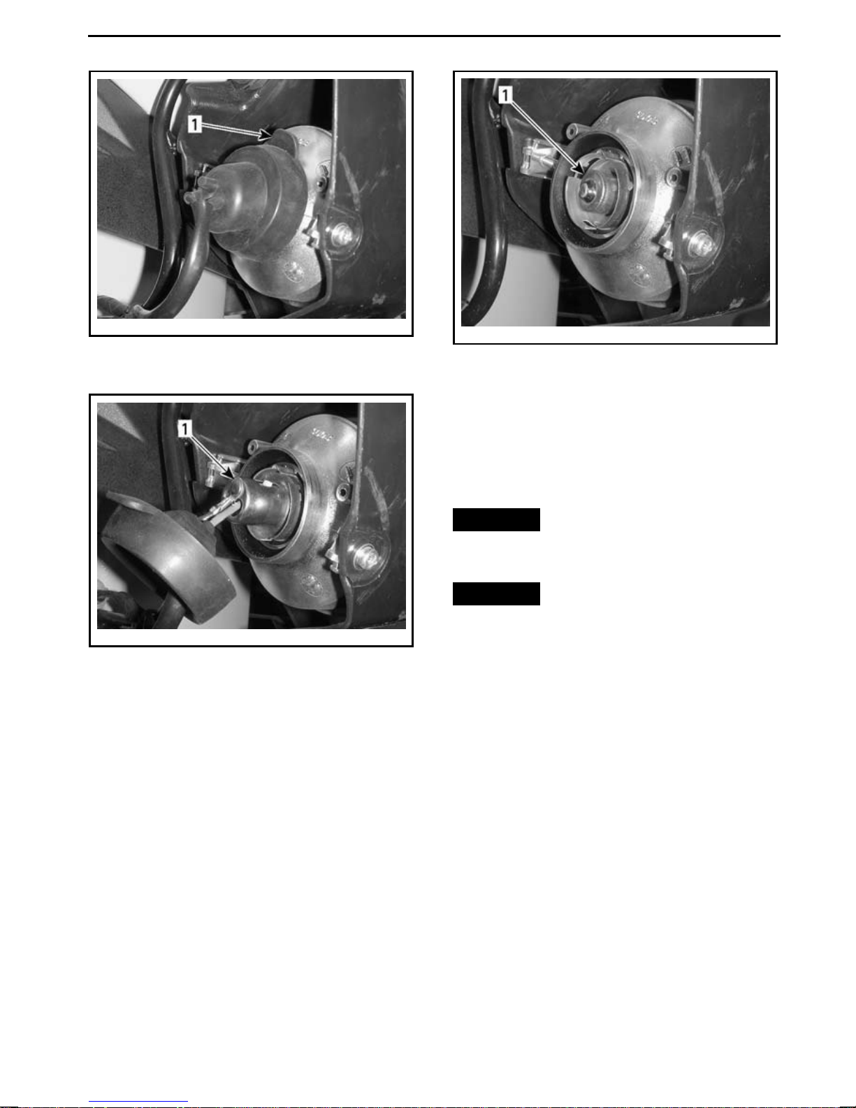
MAINTENANCE PROCEDURES
vmo2008-008-038_a
REMOVE RUBBER PROTECTOR
1. Rubber protector
vmo2008-008-039_a
PUSH AND TURN BULB HOLDER
COUNTERCLOCKWISE
1. Bu lb holder
vmo2008-008-040_a
PULL ON BULB TO REMOVE THEN REPLACE
BULB
1. Bulb
Drive Chain and Sprockets
Drive Chain and Sprocket
Inspection
NOTICE
sprockets together to prevent rapid
wear of these components.
NOTICE
cle with the drive chain too loose or
too tight as severe damage to the
drive components can occur.
Drive Chain
Inspect the chain for damaged links
and rollers.
Replace chain and
Never operate this vehi-
Replace chain if any damage is found.
Check the free-play of drive chain and
adjust if necessary. Refer to
CHAIN ADJUSTMENT
.
DRIVE
Roller
Inspect the drive chain roller around
swing arm pivot member for excessive
wear and damage. Replace if necessary.
_______________
97
Page 100
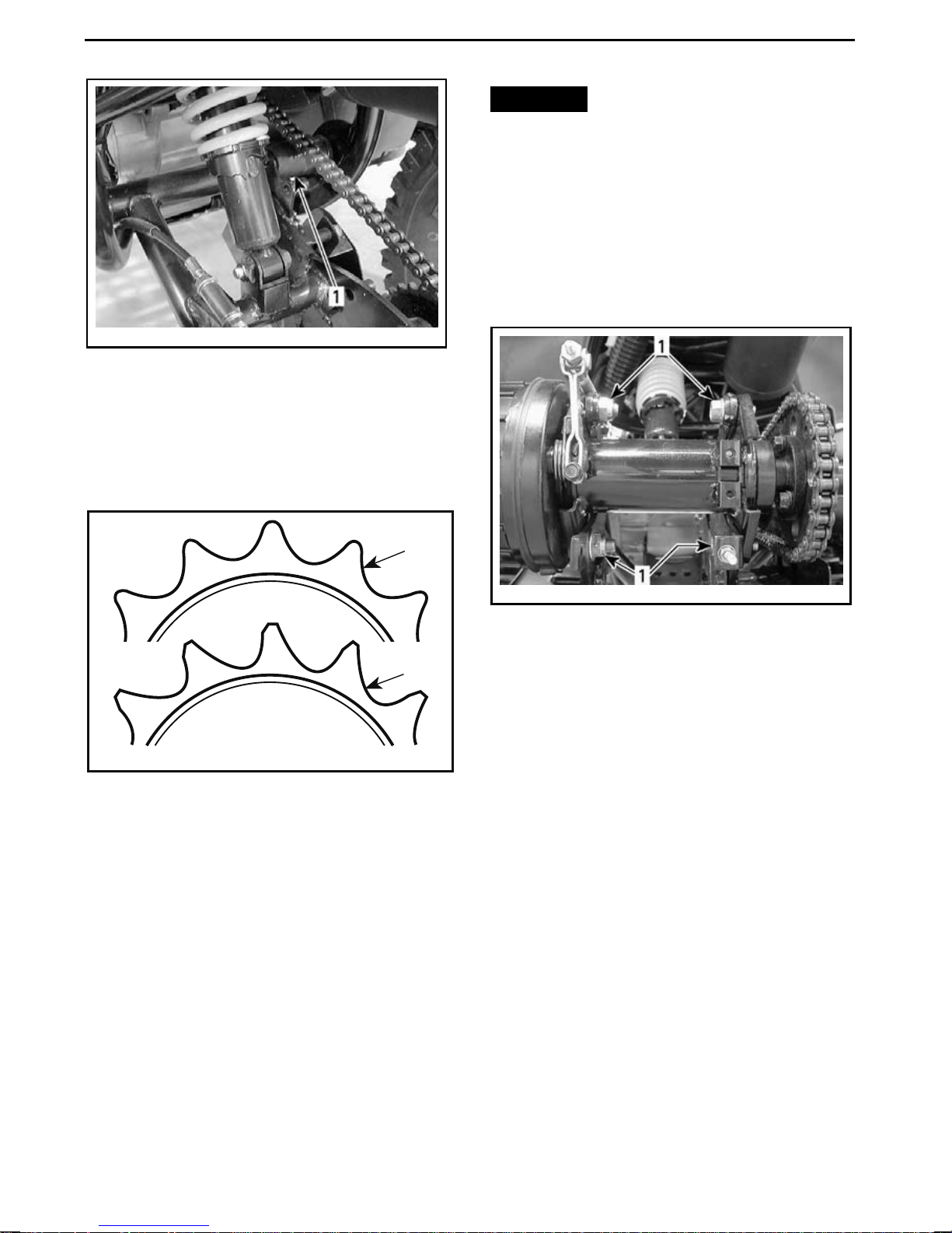
MAINTENANCE PROCEDURES
vmo2008-008-048_a
1. Drive chain roller
Sprockets
Check the sprocket axle and pinion
for d istortion, exce ss ive wear or other
damages. Replace if necessary.
1
NOTICE
Never adjust the drive
chain with t h e driver seated on the
vehicle. Remove any load on the vehicle.
1. Place vehicle on a level surface and
set transmission to NEUTRAL.
2. Check drive chain condition.
3. Loosen drive axle locking bolts.
2
V02H02Y
1. Good
2. Replace
Drive Chain Lubr ication
The drive chain should be checked for
proper lubrication before eac h ride.
Lubricateusingcommercial chainlubricant.
Drive Chain Adjustment
The drive chain should be che
cked for
proper adjustment before every ride.
vmo2008-008-046_a
TYPICAL — REAR AXL E
1. Locking bolts
4. Loosen chain adjuster lock nut.
5. On models equipped with a chain
tensioner, lift and hold the chain tensioner off the chain to release chain
tension until the chain adjustme nt is
completed.
6. Turn chain adjuster nut until proper
adjustment is obtained.
98
______________
 Loading...