

Page 1
OPERATION CONFIGURATION CALIBRATION INSTALLATION
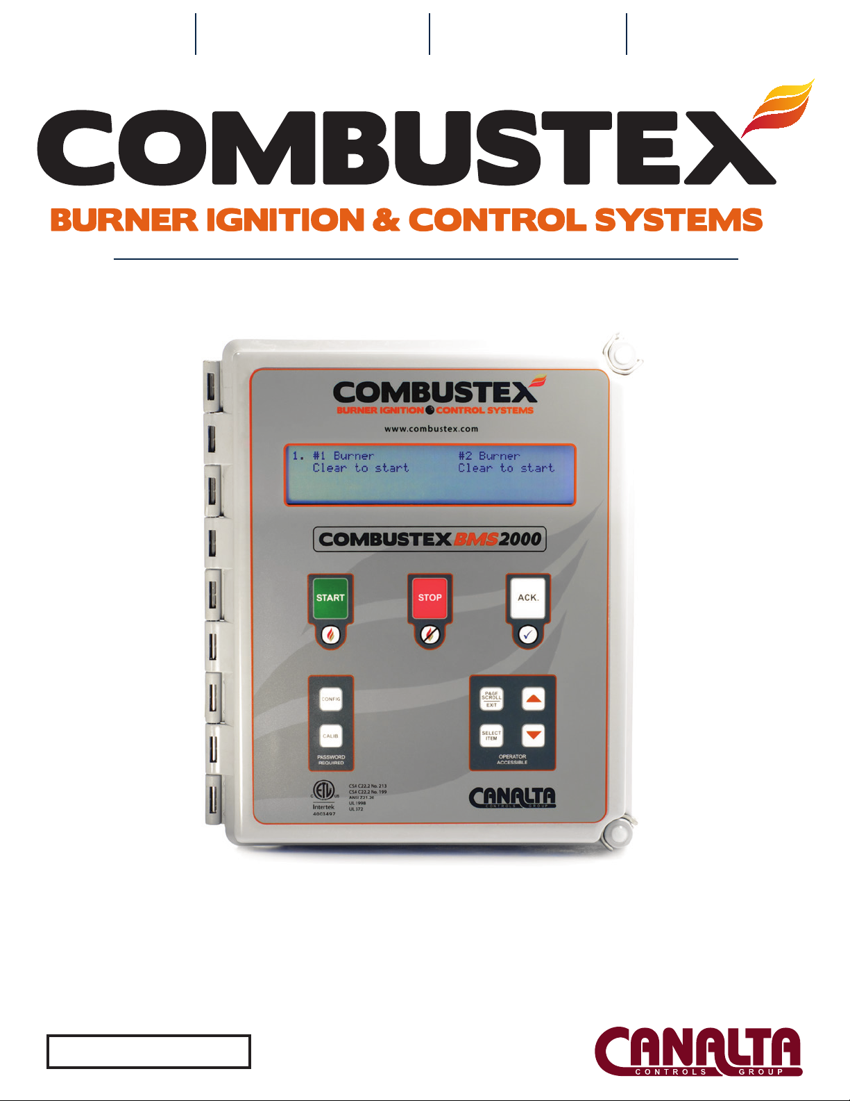
OPERATIONS MANUAL
The Combustex BMS-2000
B149.3 Compliant Burner Mangagement System
BMS Software Version 5.03
Page 2
QUALITY, RELIABILITY, PERFORMANCE
With Control Comes Safety
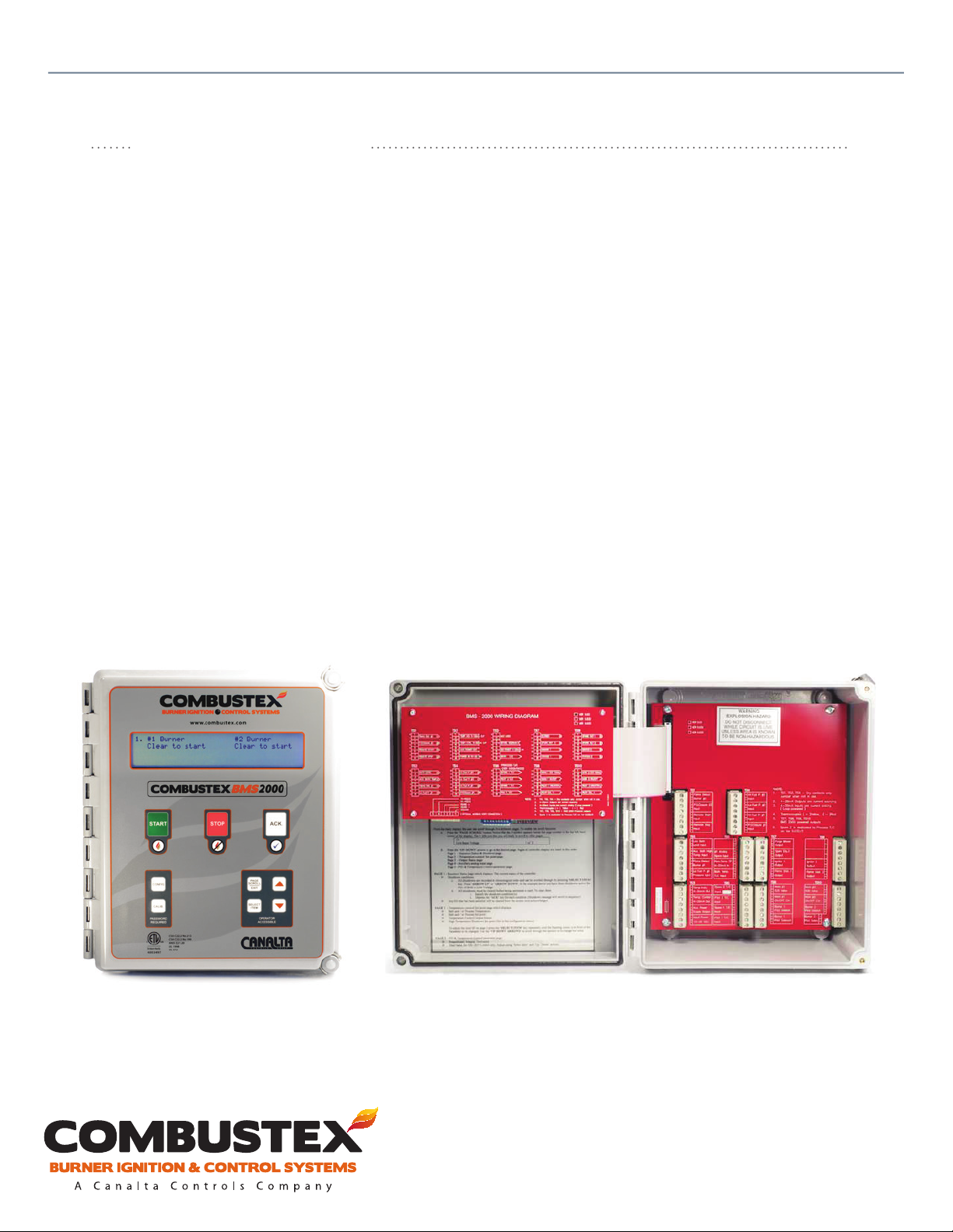
The BMS-2000 Burner Management System gives you the automated control to safely start,
monitor and manage a single or dual burner gas-red industrial heater.
• Calibrate, tune and congure more than 60 parameters and variables via the front keypad.
• Maintain system security through password protection.
• Access a wide selection of sequencing, monitoring and control information through easy page scrolling
on the heated, back-lit display.
• Gain exibility with remote and local start / shutdown / set point capabilities.
• Take control of shutdowns with rst out annunciation and a direct readout of shutdown conditions.
With the BMS-2000, You Have Exceptional Control
Standards & Certications
ANSI Z21.20 - 2007
CSA C22.2 No. 199 - B149.3 Compliant
CSA 22.2 No. 213 - M1987
UL 1998
UL 372
Class 1, Div. 2 Groups B, C and D Haz. Loc.
Temp. Code T4
NEMA Type 4x
4003497
For operational, technical or installation assistance, please contact us.
Phone: 403.342.4494 | Web: www.combustex.com
Call Us Toll Free: 1-855-226-2582
Page 3

The Combustex BMS-2000
Burner Management System
OPERATIONS MANUAL
Controller Version 5.03
WARNINGS
Combustex recommends that this manual be read thoroughly before
attempting installation or operation of the BMS-2000. SAFETY FIRST.
-- WARNING --
THIS EQUIPMENT IS SUITABLE FOR USE IN CLASS 1, DIVISION 2 GROUPS B, C, D OR
NON-HAZARDOUS LOCATIONS ONLY.
-- WARNING --
EXPLOSION HAZARD - DO NOT DISCONECT EQUIPMENT WHILE CIRCUIT IS LIVE
UNLESS AREA IS KNOWN TO BE NON-HAZARDOUS
-- WARNING --
EXPLOSION HAZARD - SUBSTITUTION OF COMPONENTS MAY IMPAIR SUITABILITY
FOR CLASS 1, DIVISION 2 LOCATIONS.
-- AVERTISSEMENT --
RISQUE D’EXPLOSION - LA SUBSTITUTION DE COMPOSANTS PEUT RENDRE CE
MATERIEL INACCEPTABLE POUR LES EMPLACEMENTS DE CLASSE 1, DIVISION 2.
-- ADVERTENCIA --
PELIGRO DE EXPLOSION - LA SUSTITUCION DE LOS COMPONENTES PUEDE
AFECTAR LA COMPATIBILIDAD PARA CLASE 1, LOCALIZACION DE DIVISION 2
For operational, technical or installation assistance, please contact us.
Phone: 403.342.4494 | Web: www.canaltaow.com
Call Us Toll Free: 1-855-226-2582
Page 4

Combustex BMS-2000 [5.03] Operations Manual
CONTENTS
1. INTRODUCTION
2
of 42
1.1 Overview
1.2 Burner Sequencing
1.3 ESD (Emergency Shutdown) Capabilities
1.4 Temperature Control
1.5 Features
1.6 Communications
1.7 Denitions of Common Terms and Abbreviations
1.8 Technical Specications
2. OPERATION
2.1 Overview
2.2 Passwords - Gaining Entry
2.3 Sequence Status & Shutdown Annunciation
2.4 Temperature Control
2.5 Output Status
2.6 Auxiliary Analog Inputs and Shutdowns
2.7 PID & Control Parameters
3. CONFIGURATION OF THE BMS-2000
3.1 Overview
3.2 Conguration Menu Options
3
4
4
5
5
6
6
6
7
9
10
12
13
13
14
15
16
4. CALIBRATION OF THE BMS-2000
4.1 Overview
4.2 Calibration Menu Items
4.3 Thermocouple / mV Reference Chart
5. INSTALLATION
5.1 Overview
5.2 Analog Input Connections
5.3 Digital Input Connections
5.4 Analog Output Connections
5.5 Digital Output Connections
5.6 Modbus Connections
5.7 Sample P&ID Drawings & Wiring Diagrams
6. TROUBLESHOOTING SHUTDOWN CONDITIONS
6.1 Error Messages and Shutdown Conditions
For operational, technical or installation assistance, please contact us.
Phone: 403.342.4494 | Web: www.canaltaow.com
25
26
27
28
29
29
30
30
30
31
37
Call Us Toll Free: 1-855-226-2582
Page 5
Combustex BMS-2000 [5.03] Operations Manual - 1. INTRODUCTION
INTRODUCTION
1.1 OVERVIEW
The Combustex BMS-2000 Burner Management System has been designed to be compatible with a wide
variety of industrial and oileld burner vessels. A common vessel will have a main burner ring into a re
tube which, in turn, heats a uid (often glycol). This uid is referred to as the “Bath”. Another uid (oil or
gas) is routed through the bath to be heated. This is referred to as the “Process”.
The BMS will control up to two pilots and two main burners, handle temperature control of the bath, and
provide ame status outputs and a variety of ESD (emergency shutdown) inputs.
The BMS-2000 is typically installed together with a Pilot Pro™ Series Ignition Assembly. These igniters
are designed and built around the features of the BMS, allowing the BMS to light and maintain a pilot
ame using the sensor that is incorporated into the pilot ignition module, providing ame verication.
The Combustex BMS-2000 is suitable for both new installations and retrotting older vessels, and is not
limited to Pilot Pro™ igniters.
3
of 42
For operational, technical or installation assistance, please contact us.
Phone: 403.342.4494 | Web: www.canaltaow.com
Call Us Toll Free: 1-855-226-2582
Page 6

Combustex BMS-2000 [5.03] Operations Manual - 1. INTRODUCTION
1.2 BURNER SEQUENCING
When initiating a start sequence, the BMS will open the pilot and energize the igniter for the trial for
ignition period and wait for the ame sensor to conrm a ame. Upon ame verication, the unit will
then go into “Normal Operation”. At this point, the BMS will energize the main burner and the ame
status output(s). The temperature control option will also become enabled (if congured).
Set points and the associated password protected timers are congurable in the BMS menu. Other
congurable options:
• Purge and Pre-purge
• Auto Relight on Flame Fail
• Auto Relight on Power Fail (unit will relight when power is restored)
1.3 EMERGENCY SHUTDOWN CAPABILITIES
4
of 42
The BMS-2000 can be congured to shut down when an unsafe or out-of-control condition exists.
1. Programmable HTSD limits on:
• Bath Thermocouple Input
• Process Thermocouple Input
• Stack Thermocouple Input
2. Standard dedicated discrete eld device inputs preset at the factory:
• Remote Stop
• Remote Start
• Low Voltage
• Burner #1 Flame Sensor Failure
• Burner #1 Flame Failure to Relight
• Burner #1 Fuel Gas Low Pressure
• Burner #1 Fuel Gas High Pressure
• Aux. High Bath Temp. (Contact)
• Low Bath Level
• Burner #1 Main Valve Proof of Closure
3. Additional inputs for Dual Burner Systems:
• Burner #2 Flame Sensor Failure
• Burner #2 Flame Failure to Relight
• Burner #2 Fuel Gas Low Pressure
• Burner #2 Fuel Gas High Pressure
• Burner #2 Main Valve Proof of Closure
For operational, technical or installation assistance, please contact us.
Phone: 403.342.4494 | Web: www.canaltaow.com
Call Us Toll Free: 1-855-226-2582
Page 7

Combustex BMS-2000 [5.03] Operations Manual - 1. INTRODUCTION
1.4 TEMPERATURE CONTROL
The BMS-2000 can be congured to perform bath temperature control by a Proportional or ON/OFF
Control output.
Proportional Control:
One 4-20mA output will be used. Set point and PID parameters are congurable via the BMS-2000
keypad.
ON/OFF Control:
The main #1 (and main #2, if applicable) burner will be cycled on and o to maintain set point. The
ON/OFF dead band and set point is adjustable via the BMS-2000 keypad.
1.5 FEATURES
Automatic Sequencing Features
5
of 42
• LCD backlight, which can be set to ON, OFF, AUTO (with photocell) or TIMED.
• LCD heater, which automatically turns on at -10°C (14°F) to maintain display stability.
• Available computer interface via RS232 or RS485 Modbus protocol.
• Input ltering to help alleviate noisy signals and signal spikes.
• Capable of driving latching solenoids (separate latch and unlatch outputs).
• Single or dual burner control (selectable in series or parallel).
• Auto relight sequence can be de-selected or selected with up to three relight attempts after loss of
ame.
• Congurable pre- and post-purge times and auxiliary blower with conrmation.
• Congurable ame sensor options.
• Ignition output signal can be congured as steady or pulsed.
• Wide variety of congurable safety interlock devices (factory set to standard settings).
• Remote start / stop is congurable.
• Auto startup after power failure is congurable.
• Intermittent pilot or standing pilot is congurable.
• Remote indication of temperatures via 4-20 mA output.
• Remote set point of bath available via 4-20 mA input.
• Conguration is password protected and stored in non-volatile memory.
Shutdown Annunciation Features
• A rst out annunciation is built in with direct readout of the shutdown conditions. Each shutdown
condition is marked with its chronological incoming position. The operator must acknowledge
each shutdown condition and the condition must be cleared before startup can be initiated.
For operational, technical or installation assistance, please contact us.
Phone: 403.342.4494 | Web: www.canaltaow.com
Call Us Toll Free: 1-855-226-2582
Page 8
Combustex BMS-2000 [5.03] Operations Manual - 1. INTRODUCTION
1.6 COMMUNICATIONS
The Combustex BMS-2000 includes both analog (9 total) and digital (28 total) connections for
communication between the BMS controller and various combustion system monitoring and control
devices. In addition, the BMS oers Modbus connectivity for fast, robust communication between the
BMS unit and remote controllers and readout devices. Modbus protocols RS232 and RS485 can be used
to remotely monitor and congure a select list of settings and status readouts. This functionality is
available in both single and dual-burner versions of the Combustex BMS-2000.
1.7 DEFINITIONS AND ABBREVIATIONS
Dead Band The allowed deviation from set point (while in ON/OFF Control)
DI Discrete Input
ESD Emergency Shutdown
HTSD High Temperature Shutdown
LCD Liquid Crystal Display
PID Proportional, Integral (Reset), Derivative (Rate)
PV Process Variable (Actual Temperature)
SD or S/D Shutdown
SP Set Point (Desired Temperature)
6
of 42
1.8 TECHNICAL SPECIFICATIONS
Rating CSA Class 1, Div. 2; Class 1, Div. 1 (pending); Intrinsically Safe; Nema 4x; B149.3 Compliant
Enclosure Dimensions 10.5” H, 8.5” W, 6” D
Enclosure Construction Molded Fiberglass Polyester with Quick Release Latches
Operating Temperature - 40°C to + 40°C (-40°F to +104°F)
Inputs
Outputs
Power Supply 12 to 30 VDC Clean Filtered
80 mA (min), 160 mA (typical), 300 mA (max) for Electronics + LCD Backlight + Display
Current Draw
Display Low Temp. Heated LCD
Mounting Wall Mount Bracket Standard; 2” Pipe Mount Optional
Communication Digital, Analog and Modbus
(5) Thermocouple Type K Underground Cold Junction Compensated
(16) 12-30 VDC Digital Solid State Optical Isolated (1.5A each)
Heater. Current draw of solenoids and other devices driven by BMS will have to be
added to above to calculate total. Total current draw not to exceed 3A.
(12) Digital Solid State; (2) Analog 4-20mA;
(2) Analog 4-20mA 500 Ohm (max.)
For operational, technical or installation assistance, please contact us.
Phone: 403.342.4494 | Web: www.canaltaow.com
Call Us Toll Free: 1-855-226-2582
Page 9
Combustex BMS-2000 [5.03] Operations Manual - 2. OPERATION
OPERATION
2.1 OVERVIEW
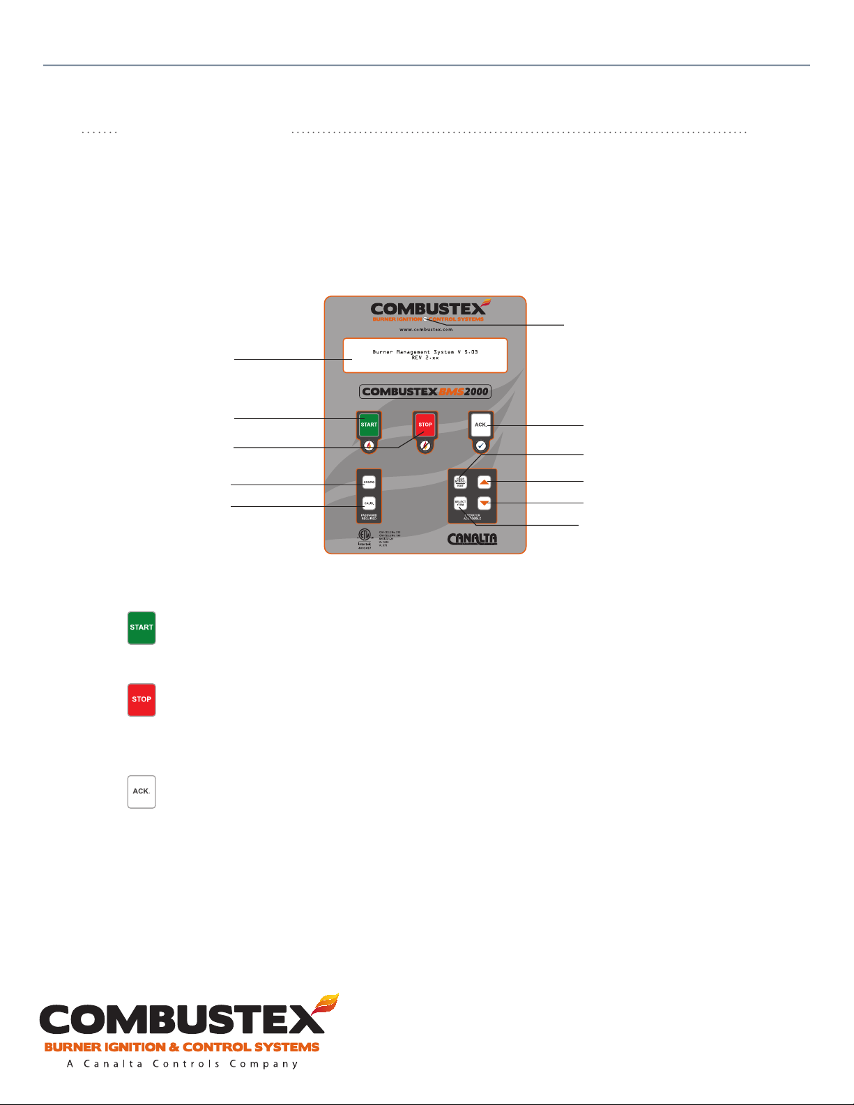
The operator interface of the BMS-2000 consists of two components:
• Heated, Back-lit LCD Alphanumeric Display
• 9-Key Membrane Keypad
LCD Display
Auto Backlight Sensor
7
of 42
Start Key
Stop Key
Configuration Key
Calibration Key
Acknowledge Key
Page Scroll Key
Up Key
Down Key
Select Item Key
Keypad functions:
• START initiates the automatic ignition sequence of the pilot and BMS. Once the pilot ame is
proven, the BMS will continue into NORMAL OPERATION.
Note: the BMS display must read “CLEAR TO START” in order to initiate startup sequence.
• STOP cancels the ignition sequence and / or shutdown the operation of the BMS and pilot
by closing all fuel train valves and extinguishing the pilot ame. A shutdown reading
of “LOCAL MANUAL S/D” will be displayed on BMS display page 1, indicating the STOP
button has been pressed.
• ACK clears any active shutdowns displayed on BMS display page 1. This key also acknowledges
passwords and selects items in the calibration and conguration menus for adjustment.
Note: active shutdowns will only be cleared from the display if they have been cleared in the
eld and a safe condition exists. If the ACK button is pressed and a shutdown has not
been eld-cleared, a * symbol will appear beside the shutdown, indicating that it has
been acknowledged by the operator, but the error still exists in the eld.
For operational, technical or installation assistance, please contact us.
Phone: 403.342.4494 | Web: www.canaltaow.com
Call Us Toll Free: 1-855-226-2582
Page 10
Combustex BMS-2000 [5.03] Operations Manual - 2. OPERATION
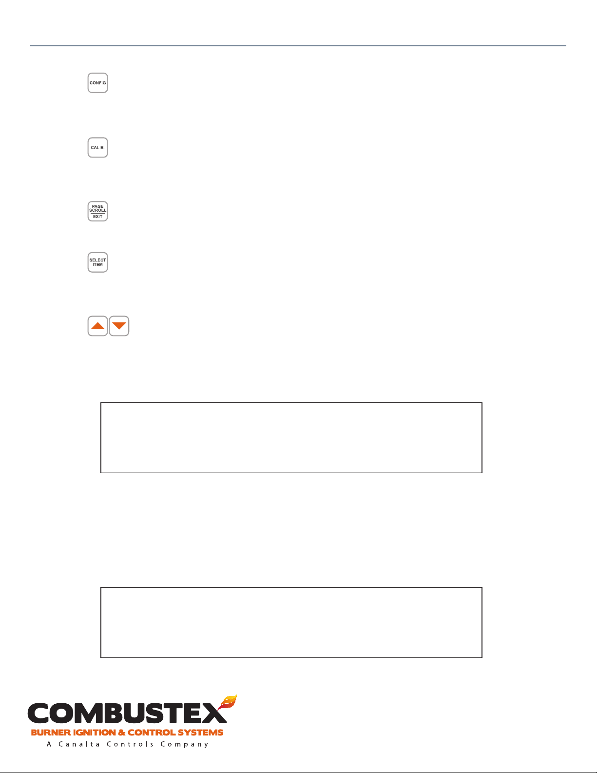
• CONFIG allows the user access to the Conguration Menu.
Note: BMS must be shut down (not in NORMAL OPERATION) in order to access the
Conguration Menu.
Note: Conguration Menu is password protected.
• CALIB allows the user access to the Calibration Menu.
Note: BMS must be shut down (not in NORMAL OPERATION) in order to access the
Calibration Menu.
Note: Calibration Menu is password protected.
• PAGE SCROLL / EXIT displays a > symbol beside the page number in the top left corner of the
BMS display, indicating that the user may scroll through the pages by pressing the arrow keys.
PAGE SCROLL is also used to exit the Conguration and Calibration Menus.
• SELECT ITEM allows the user to scroll through any active shutdowns on BMS display page 1,
change the control parameters on page 2, and adjust settings on pages 4 and 5 (using the
arrow keys). SELECT ITEM also moves the cursor from right to left when inputting any
password or numerical value.
8
of 42
• The arrows are used to scroll through pages, scroll through the Conguration and
Calibration Menus, and adjust settings and numerical values.
Upon power-up, the introduction message and controller version will be displayed:
Burner Management System V 5.03
REV 2.xx
From the main display, the user can scroll through ve dierent pages.
To enable the scroll function:
1. Press the ‘PAGE SCROLL’ button. Notice that the > symbol appears beside the page number in the
top left-hand corner of the display.
2. Press the and buttons to go to the desired page.
1>
Low Input Voltage 1 of 3
For operational, technical or installation assistance, please contact us.
Phone: 403.342.4494 | Web: www.canaltaow.com
Call Us Toll Free: 1-855-226-2582
Page 11

Combustex BMS-2000 [5.03] Operations Manual - 2. OPERATION
Pages are displayed in the following order:
Page 1 - Sequence Status & Shutdown
Page 2 - Temperature Control / Set Point
Page 3 - Output Status
Page 4 - Auxiliary Analog Input
Page 5 - PID & Temperature Control Parameter
2.2 PASSWORDS - GAINING ENTRY
The controller will be precongured at time of order, making changes to the unit’s conguration and
calibration unnecessary.
The BMS-2000 has a congurable 4-digit password which can be used to prevent unauthorized personnel
from altering conguration, calibration or temperature control parameters. Once in the conguration
menu, the ‘USER’ password can be changed to a dened value.
9
of 42
Whenever the BMS asks for the password, use the ‘SELECT ITEM’ and and buttons to change the
password, then press the ‘ACK’ key.
If the ‘USER’ password has been congured, use that value. If the ‘USER’ password has not been
congured, use the ‘MASTER’ password.
Factory presets are as follows:
MASTER - Password is 1313 and can be used if ‘USER’ password is forgotten.
USER - Same entry level as ‘MASTER’ but user-dened (see section 3.2 item 39).
CONFIG - Manufacturer and authorized personnel (password = 0065).
CALIB - Manufacturer and authorized personnel (password = 0067).
Feature access is as follows:
ACCESS TYPE MASTER USER CONFIG CALIB
View CONFIG Menu Items YES YES YES YES
Change Enabled CONFIG Menu Items YES YES YES YES
Change Locked CONFIG Items NO NO YES NO
View CALIB Menu Items YES YES YES YES
Change CALIB Menu Items NO NO NO YES
View PAGE 5 (PID, ON/OFF Parameters) YES YES YES YES
Change PID / ON/OFF Control Parameters YES YES YES YES
For operational, technical or installation assistance, please contact us.
Phone: 403.342.4494 | Web: www.canaltaow.com
Call Us Toll Free: 1-855-226-2582
Page 12

Combustex BMS-2000 [5.03] Operations Manual - 2. OPERATION
2.3 SEQUENCE STATUS & SHUTDOWN ANNUNCIATION
Page one on the controller display is the Sequence / Status page which displays:
• The current status of the controller
• Shutdown conditions
All shutdowns are recorded in chronological order and can be scrolled through.
1. Press the ‘SELECT ITEM’ key
2. Press the and buttons
In the example below, three shutdowns are active, the rst of which is due to low voltage.
1.
Low Input Voltage 1 of 3
10
of 42
All shutdowns must be cleared before being permitted to proceed. To clear them:
1. Satisfy the shutdown condition(s)
2. Depress the ‘ACK’ key for each condition (shutdown message will scroll in sequence)
1.
*Remote Shutdown 2 of 3
Note:
• Any shutdown which has been acknowledged will have an asterisk (*) preceding the text.
• Any condition that has been satised will be cleared from the screen, providing it has been
acknowledged. Note: See section 6 for troubleshooting shutdown conditions (pp. 37 - 41).
After all shutdowns have been cleared and acknowledged, the following will be displayed:
1.
Clear to Start
For operational, technical or installation assistance, please contact us.
Phone: 403.342.4494 | Web: www.canaltaow.com
Call Us Toll Free: 1-855-226-2582
Page 13
Combustex BMS-2000 [5.03] Operations Manual - 2. OPERATION
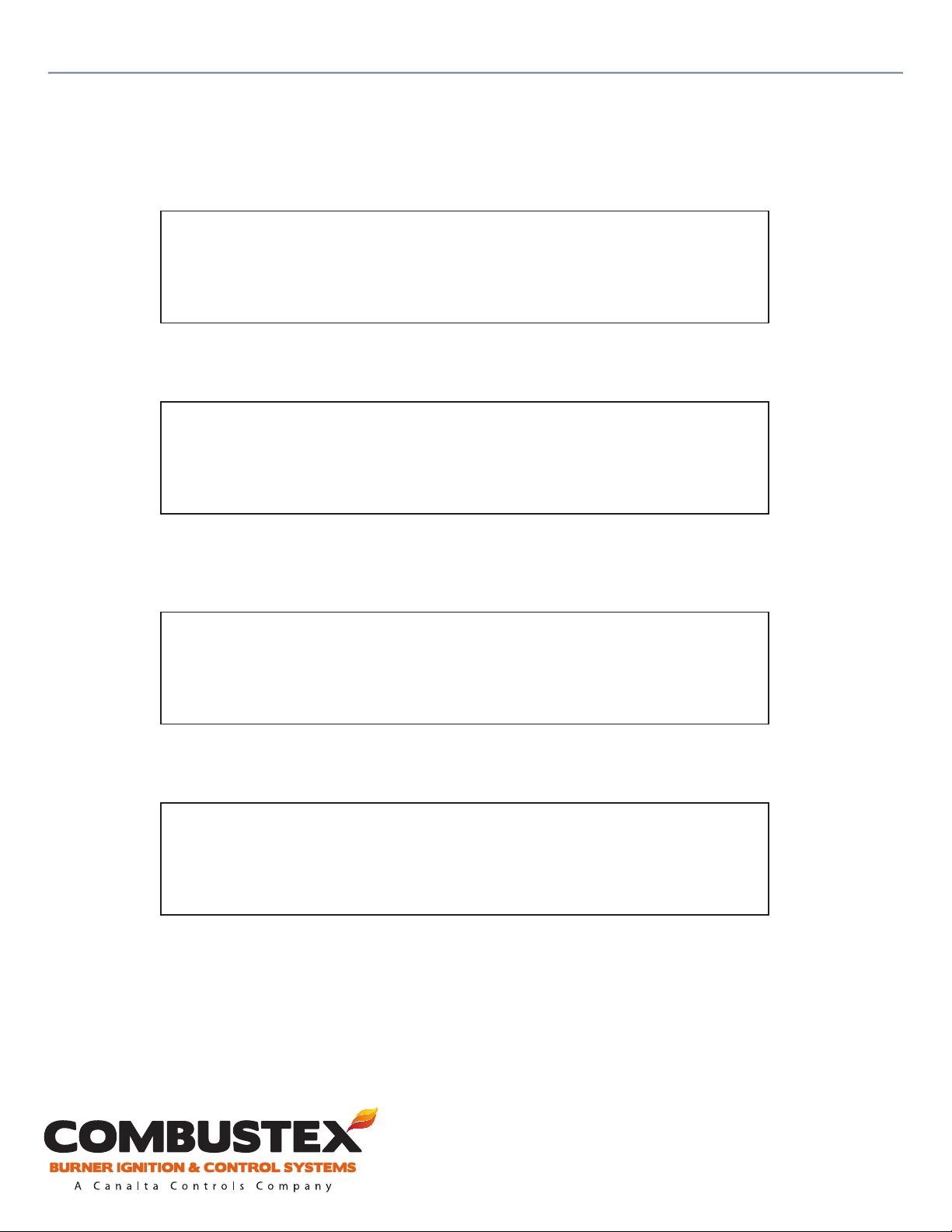
The BMS-2000 is now ready to relight the burner. The following message appears after depressing the
‘START’ button (ignitor is on Preset Trial for Ignition Period):
1.
Ignition ON
The following message is displayed once the system has veried the pilot ame:
1.
#1 Burner
Normal Mode
11
of 42
If, after reaching “Normal Mode”, the pilot ame goes out, the following message will be displayed
(provided relight attempts have been enabled):
1.
Relight Attempt #1
Purge On
After the preset purge time, the relight ignition sequence is initiated.
1.
Relight Attempt #1
Ignition On
For operational, technical or installation assistance, please contact us.
Phone: 403.342.4494 | Web: www.canaltaow.com
Call Us Toll Free: 1-855-226-2582
Page 14

Combustex BMS-2000 [5.03] Operations Manual - 2. OPERATION
2.4 TEMPERATURE CONTROL
Temperature control is accessed on page two of the BMS-2000 controller display. This page displays:
• Bath and/or Process Temperature
• Bath and/or Process Set Point
• Temperature Control Output Status
• HTSD Set Point (as set in the conguration menu)
2. Bath: +21C
SP : +70C Loc.
OUT.: 90% Auto
HTSD: +95C
* Note: Displayed temperature units are specied at time of order.
While viewing this page, the operator can:
12
of 42
• Adjust the Local Set Point
• Switch between Local, Remote or Serial Set Point Control
• Adjust ‘Manual’ Control’s Output Value
To make these changes:
1. Depress the ‘SELECT ITEM’ key repeatedly until the ashing cursor is in front of the parameter to be
changed.
2. Use the and buttons to scroll through the options or to change the value.
NOTES:
• When congured for proportional control, the output will be displayed in ‘%’.
• When congured for ON/OFF control, the output will be displayed as ‘ON’ or ‘OFF’.
• Set point input oers three options:
• Loc. = Local (from BMS keypad)
• Rem. = Remote (via 4-20mA signal) - ‘REMOTE SP I/P’ must be enabled in conguration
• Ser. = Serial (computer interface, RS 232/485)
For operational, technical or installation assistance, please contact us.
Phone: 403.342.4494 | Web: www.canaltaow.com
Call Us Toll Free: 1-855-226-2582
Page 15

Combustex BMS-2000 [5.03] Operations Manual - 2. OPERATION
2.5 OUTPUT STATUS PAGE
Page three of the BMS-2000 controller displays the status of the following:
• Pilot Solenoid Valve
• Main Solenoid Valve
• Ignition Output
• Purge Blower Output
3. #1 Pilot : Open
#1 Main : Open
#1 Ign. : Off
Purge Blower: Off
NOTE: This page is non-adjustable and is for indication only.
13
of 42
2.6 AUX. ANALOG INPUTS AND SHUTDOWNS
Page four of the BMS-2000 controller displays two monitored values:
• Spare Thermocouple Input #1 (if selected)
• This value can be labeled as ‘ #1 Stack’, ‘Bath’ or ‘Process’
• Input can be used for indication only, or as a HTSD
• When used as a HTSD, this value appears in brackets beside the actual temperature
• Supply Voltage
4. #1 Stack : +315C [+700]
Supply Voltage : +24V [+20]
* Note: Displayed temperature units are specied at time of order.
NOTE: This page is non-adjustable and is for indication only. Shutdown limits, which appear in brackets,
are denable in the conguration menu (see section 3.2).
For operational, technical or installation assistance, please contact us.
Phone: 403.342.4494 | Web: www.canaltaow.com
Call Us Toll Free: 1-855-226-2582
Page 16

Combustex BMS-2000 [5.03] Operations Manual - 2. OPERATION
2.7 PID & CONTROL PARAMETER PAGE
NOTE: This page is password protected. See section 2.2.
Page ve of the BMS-2000 controller display allows the adjustment of four parameters relating to
temperature control:
• Proportional, for PID control only
• Integral (Reset), for PID control only
• Derivative (Rate), for PID control only
• Dead Band, for ON/OFF control only
To make these adjustments:
1. Depress the ‘SELECT ITEM’ key repeatedly until the ashing cursor is in front of the parameter to be
changed.
2. Use the and buttons to change the value.
14
of 42
5. Prop. Band (%) Bath: 50
Reset (Min/Rpt) Bath: 0.00
Rate (Min) Bath: 0.00
D.Band (Deg C) Bath: 2
* Note: Displayed temperature units are specied at time of order.
NOTES:
• If the Rate or Reset values are equal to zero, they are disabled.
• All of the above parameters can be changed during startup or normal operation.
For operational, technical or installation assistance, please contact us.
Phone: 403.342.4494 | Web: www.canaltaow.com
Call Us Toll Free: 1-855-226-2582
Page 17
Combustex BMS-2000 [5.03] Operations Manual - 3. CONFIGURATION
CONFIGURATION
3.1 OVERVIEW
The BMS-2000 Burner Management System is congured by adjusting a series of password protected
menu items. This menu is accessed by depressing the ‘CONFIG’ key on the BMS keypad.
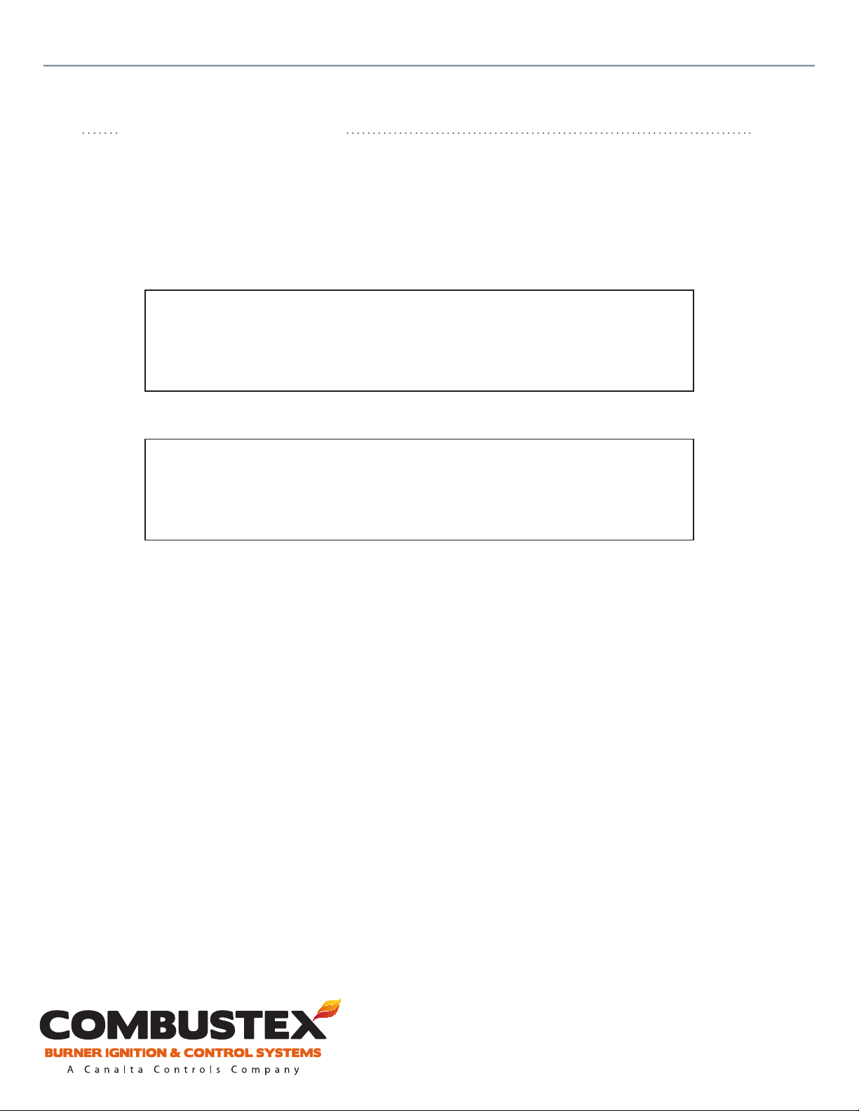
Initial Display
Burners
Parallel
Parameter open for change (signied by > symbol)
15
of 42
Burners
>Parallel
To congure the BMS-2000:
1. Use the and buttons to navigate through the menu items.
2. Select an item for conguration by depressing the ‘ACK’ button. The > symbol will appear behind
the variable to be changed.
3. Use the and buttons to scroll through the list of options.
4. When a numerical value appears and the cursor is ashing, the value is open for adjustment. Use
the ‘SELECT ITEM’ key to move the cursor and the and buttons to change it.
5. If a numerical value appears in a list of options, depress the ‘ACK’ key again to get the cursor to
ash.
6. Depress the ‘ACK’ key to conrm selection. Notice the > symbol disappear.
7. Resume scrolling through the menu items.
8. Depress the ‘PAGE SCROLL’ button to exit from the CONFIG menu.
NOTES:
• The BMS-2000 is pre-congured at the factory, and the CONFIG menu is password protected. See
section 2.2.
• All shutdowns are factory set to YES by default. If a specic shutdown is not required, it must be
manually set to NO in the CONFIG menu. An active shutdown with no eld device will result in an error message and the controller will NOT be permitted to START.
• The CONFIG menu cannot be accessed while the BMS is in operation.
For operational, technical or installation assistance, please contact us.
Phone: 403.342.4494 | Web: www.canaltaow.com
Call Us Toll Free: 1-855-226-2582
Page 18
Combustex BMS-2000 [5.03] Operations Manual - 3. CONFIGURATION
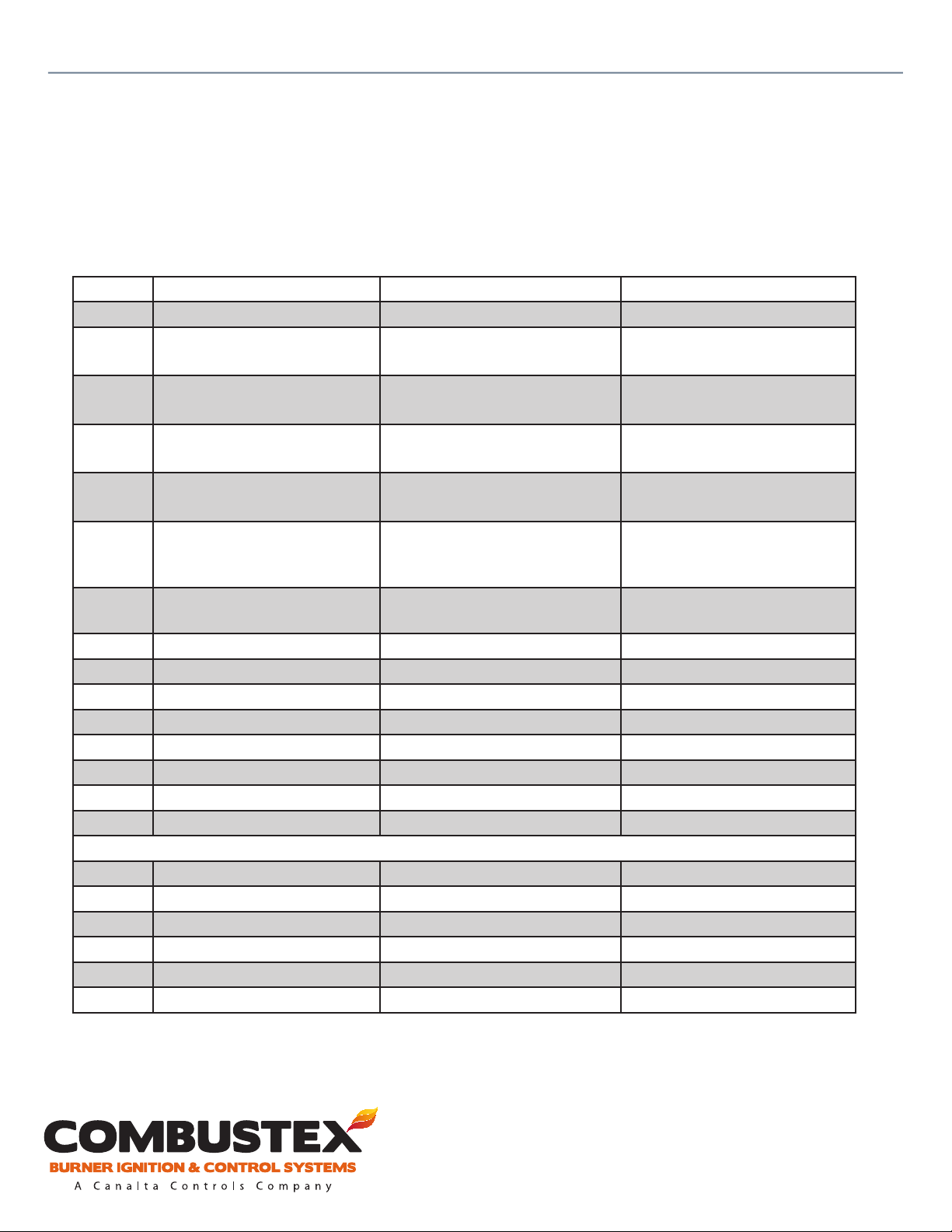
3.2 CONFIGURATION MENU ITEMS
Below are the BMS-2000 Version 5.03 CONFIG menu items and their options. See pp. 17 - 23 for a
description of each.
Item # Sequencing Items Available Options Notes
1 Burners 1 / 2 / Dual Parallel / Dual Series
2 #1 T/C Flame 1st Level
3 #1 T/C Flame 2nd Level
4 #2 T/C Flame 1st Level
5 #2 T/C Flame 2nd Level
6 Trial for Ignition Timer
7 Flame T/C 2nd Level Timer
8 Purge Timer 0 - 10.0 Minutes
9 Pre-purge Yes / No
10 Ignition Steady / Pulsed
11 Relight Attempts 0 / 1 / 2 / 3
12 Flame Detection Contact / T/C / Aux Contact
13 Remote Start Yes / No
14 Remote Stop Yes / No
15 Power Failure Auto Relight Yes / No
16 Proof of Closure #1 Yes / No
17 Proof of Closure #2 Yes / No
18 Pilot Continuous / Intermittent
19 Flame Status Independent / Common
20 Fuel Low Pressure #1 Yes / No
21 Fuel High Pressure #1 Yes / No
0 - 800°C (32 - 1472°F)
Preset at 250°C (482°F)
0 - 800°C (32 - 1472°F)
Preset at 450°C (842°F)
0 - 800°C (32 - 1472°F)
Preset at 250°C (482°F)
0 - 800°C (32 - 1472°F)
Preset at 450°C (842°F)
0 - 3.0 Minutes
Preset to .15 (9 sec) for “Contact”
Preset to 2 for “T/C”
0 - 5.0 Minutes
Preset to 3 for “T/C”
Safety Interlocks
N/A when “Flame Detection” cong-
ured to “Contact” (ame rod, UV)
N/A when “Flame Detection” cong-
ured to “Contact” (ame rod, UV)
N/A when “Flame Detection” cong-
ured to “Contact” (ame rod, UV)
N/A when “Flame Detection” cong-
ured to “Contact” (ame rod, UV)
Preset to 9 sec. when “Flame Detection” congured to “Contact” (ame
rod, UV)
N/A when “Flame Detection” cong-
ured to “Contact” (ame rod, UV)
16
of 42
For operational, technical or installation assistance, please contact us.
Phone: 403.342.4494 | Web: www.canaltaow.com
Call Us Toll Free: 1-855-226-2582
Page 19

Combustex BMS-2000 [5.03] Operations Manual - 3. CONFIGURATION
Conguration Menu Items cont’d
Item # Sequencing Items Available Options Notes
22 Fuel Pressure #2
23 Spare Temp. T/C #1
24 Spare Temp. #1 T/C Label
25 Spare Temp. T/C #2
26 Spare Temp. #2 T/C Label
27 Allow Auto / Manual
28 Control Mode
29 Main Bath T/C High Temp.
30 Bath High Temp. (Contact)
31 Bath Low Level
32 Low Voltage
33 Spare Analog Input S/D
34 Control Output Mode
35 Remote Set Point I/P
36 Remote Temp. Indicate O/P
37 Backlight
38 Audio
39 New Access Code
40 R.F. Filter
41 L.P. Filter (Pilot, Spare #1)
42 L.P. Filter (Bath, Spare #2)
43 Modbus Address
None / Hi Press / Hi & Low Press
None / Indicate Only /
0 - 800°C (32 - 1472°F)
Stack #1 / Bath / Process
None / Indicate Only /
0 - 800°C (32 - 1472°F)
Stack #2 / Bath / Process
Yes / No
None, Proportional, On-O
No / 0 - 600°C (32 - 1112°F)
Yes / No
Yes / No
10 - 30 Volts
None / Indicate Only / 0 - 100%
Temperature Control
Steady / Latching Pulse
Yes / No
Yes / No
Operational
Steady On / O / Light Activated / Timed
Yes / No
0 - 9999
0 - 1000
0 - 9999
0 - 9999
0 - 247
17
of 42
For operational, technical or installation assistance, please contact us.
Phone: 403.342.4494 | Web: www.canaltaow.com
Call Us Toll Free: 1-855-226-2582
Page 20
Combustex BMS-2000 [5.03] Operations Manual - 3. CONFIGURATION
18
of 42
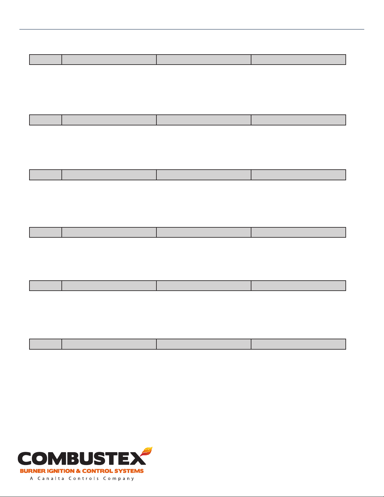
1 Burners
1 / 2 / Dual Parallel / Dual Series
• Burner 1 operates only (see P&ID drawings pp. 31 - 15).
• Burner 2 operates only.
• Parallel - Dual Burner System. Both burners will run independently of each other
• Series - Dual Burner System. Both burners will shut down on any single ame fail.
2 #1 T/C Flame 1st Level
0 - 800°C (32 - 1472°F)
This value represents the rst level of the ame proving sequence for burner #1 if “Flame Detection” is
congured to Thermocouple. Main burner #1 is allowed to open after crossing this set point. Preset at
250°C (482°F).
3 #1 T/C Flame 2nd Level
0 - 800°C (32 - 1472°F)
This value represents the nal level of ame verication for burner #1 if “Flame Detection” is congured
to Thermocouple. Burner #1 will go into Normal Operation upon crossing this set point. Preset at 450°C
(842°F).
4 #2 T/C Flame 1st Level
0 - 800°C (32 - 1472°F)
This value represents the rst level of the ame proving sequence for burner #2 if “Flame Detection” is
congured to Thermocouple. Main burner #1 is allowed to open after crossing this set point. Preset at
250°C (482°F).
5 #2 T/C Flame 2nd Level
0 - 800°C (32 - 1472°F)
This value represents the nal level of ame verication for burner #1 if “Flame Detection” is congured
to Thermocouple. Burner #1 will go into Normal Operation upon crossing this set point. Preset at 450°C
(842°F).
6 Trial for Ignition
0 - 3.0 Minutes
This value sets the amount of time the BMS will allow for the Flame Sensor to verify a ame. If the ame
sensor does not send signal to BMS verifying a ame in the prescribed time, the ignition sequence is
halted. Preset for 10 seconds on contact input.
For operational, technical or installation assistance, please contact us.
Phone: 403.342.4494 | Web: www.canaltaow.com
Call Us Toll Free: 1-855-226-2582
Page 21
Combustex BMS-2000 [5.03] Operations Manual - 3. CONFIGURATION
19
of 42
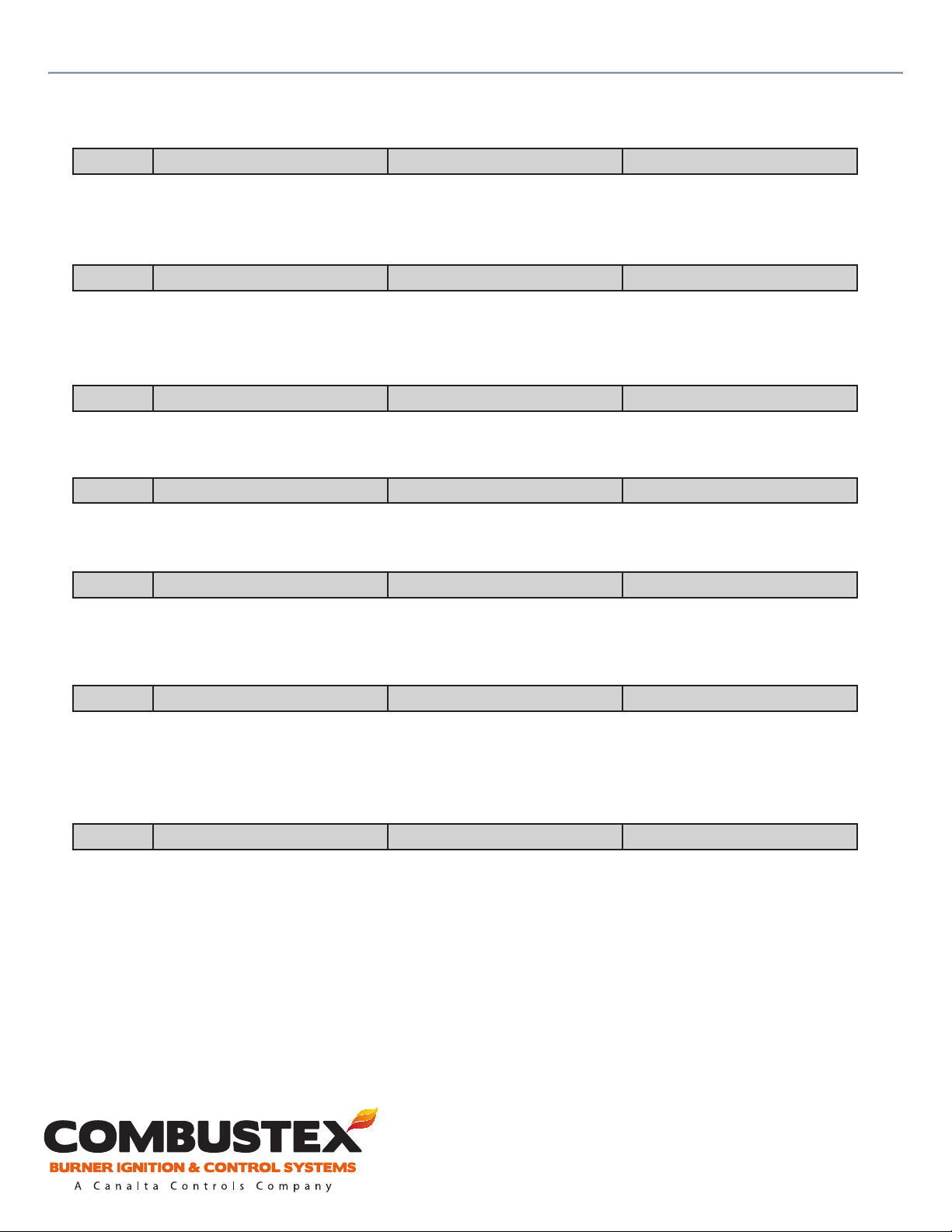
7 Flame T/C 2nd Level Timer
0 - 5.0 Minutes
This value sets the amount of time the BMS will allow for the ame to reach the second set point. The
ignition sequence is halted if the ame fails to reach the second set point in this time.
8 Purge Timer
0 - 10.0 Minutes
Purge is a prescribed time delay before relight on ame-fail. This value sets the pre- and post-purge time.
Preset as required and password protected.
9 Pre-purge
Yes / No
Pre-purge is a time delay before any start. Pre-purge utilizes the same timer as the Purge function.
10 Ignition
Steady / Pulsed
The igniter output can be a steady 24VDC, or a pulsed (5 Hertz, 20% duty cycle) 24 Volt output.
11 Relight Attempts
0 / 1 / 2 / 3
Note: The BMS-2000 will not initiate an auto re-ignition unless the unit was in normal operation at the
time of ame fail and the purge timer has timed out.
12 Flame Detection
Contact / T/C / Aux. Contact
• Contact: The unit will rely solely on the contact input from a ame sensor. B149.3 compliant.
• Thermocouple: The unit relies solely on the pilot T/C temperature for ame detection.
• Aux. Contact: The unit will require both T/C and Contact inputs to be valid for ame detection.
13 Remote Start
Yes / No
If yes, then rst momentary contact closure will try and clear shutdowns. Second momentary contact will
achieve remote start if shutdowns no longer exist.
For operational, technical or installation assistance, please contact us.
Phone: 403.342.4494 | Web: www.canaltaow.com
Call Us Toll Free: 1-855-226-2582
Page 22
Combustex BMS-2000 [5.03] Operations Manual - 3. CONFIGURATION
20
of 42
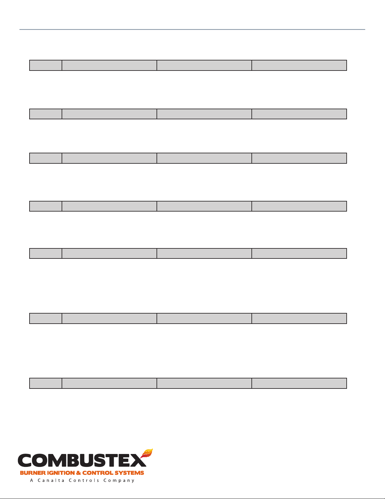
14 Remote Stop
Yes / No
If enabled, this momentary input is used to remotely shut down the BMS-2000. Most commonly used as
an ESD input.
15 Power Failure Relight
Yes / No
If enabled, the unit will automatically relight when the power is restored after failure. Unit will only
attempt relight if it was in normal operation at time of failure.
16 Proof of Closure #1
Yes / No
If enabled, the unit will require proof of closure from burner #1 main valve before ignition sequence will
be enabled.
17 Proof of Closure #2
Yes / No
If enabled, the unit will require proof of closure from burner #2 main valve before ignition sequence will
be enabled.
18 Pilot
Continuous / Intermittent
• When utilizing ON/OFF temperature control, the main burner is cycled on and o to maintain bath
and/or process set point.
• Continuous = Pilot remains on continuously
• Intermittent = Pilot turns o with the main burner. The pilot is then relit when the unit calls for heat.
19 Flame Status
Independent / Common
For Dual Burner Systems:
• Independent: Status #1 and Status #2 will reect the status of their respective burners.
• Common: Both Status #1 and Status #2 outputs will turn o if either one of the burner ames goes
out.
20 Fuel Low Pressure #1
Yes / No
Enables this contact input to be used as a shutdown.
For operational, technical or installation assistance, please contact us.
Phone: 403.342.4494 | Web: www.canaltaow.com
Call Us Toll Free: 1-855-226-2582
Page 23
Combustex BMS-2000 [5.03] Operations Manual - 3. CONFIGURATION
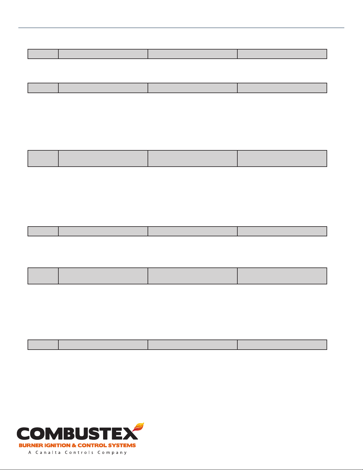
21
of 42
21 Fuel High Pressure #1
Yes / No
Enables this contact to be used as a shutdown.
22 Fuel Pressure #2
None / Hi Press / Hi & Low Press
Two contact inputs are available for shutdown purposes. These are tagged as “High Fuel Pressure #2” and
“Low Fuel Pressure #2”.
• None: Both inputs are disabled
• Hi Press: High Fuel Pressure Burner #2 is enabled
• Hi & Low Press: High Fuel Pressure Burner #2 and Low Fuel Pressure Burner #2 are enabled.
23 Spare Temp T/C #1
None / Indicate Only /
0 - 800°C (32 - 1472°F)
This item congures the spare #1 thermocouple input.
• None: Controller will disable this input.
• Indicate Only: Temperature will be displayed on page ve.
• Numeric Value: Temperature will be displayed and the unit will shut down when this congured
numeric temperature setting is crossed.
24 Spare Temp T/C #1 Label
Stack #1 / Bath / Process
This applies the label to the previous thermocouple input. Whatever tag is chosen is displayed on page
ve. The “Bath” tag here should not be confused with the dedicated bath thermocouple input.
25 Spare Temp T/C #2
None / Indicate Only /
0 - 800°C (32 - 1472°F)
This item congures the spare #2 thermocouple input.
• None: Controller will disable this input.
• Indicate Only: Temperature will be displayed on page ve.
• Numeric Value: Temperature will be displayed and the unit will shut down when this congured
numeric temperature setting is crossed.
26 Spare Temp T/C #2 Label
Stack #2 / Bath / Process
This applies the label to the previous thermocouple input. Whatever tag is chosen is displayed on page
ve. The “Bath” tag here should not be confused with the dedicated bath thermocouple input.
For operational, technical or installation assistance, please contact us.
Phone: 403.342.4494 | Web: www.canaltaow.com
Call Us Toll Free: 1-855-226-2582
Page 24
Combustex BMS-2000 [5.03] Operations Manual - 3. CONFIGURATION
22
of 42
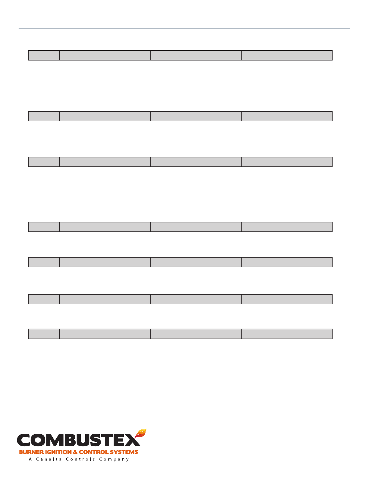
27 Control Mode
Proportional / On-O / None
• Proportional: The unit will output a 4-20mA loop for the purpose of temperature control.
• On-O: The unit will cycle the main burner(s) to maintain temperature.
• None: The unit will not monitor the bath T/C, or output any form of temperature control. This
selection is used when temperature control is provided externally to the BMS-2000.
28 Allow Auto / Manual
Yes / No (password protected)
• Yes: Allows access to the main output A/M option via the front screen.
• No: Controller output will stay in auto mode.
29 Main Bath T/C High Temp SD
No / 0 - 600°C (32 - 1112°F)
This temperature is read o of the dedicated bath thermocouple.
• No: Controller will not use the bath T/C for HTSD.
• Yes: Controller will use the bath T/C for HTSD and will shut down when this congured numeric
temperature setting is crossed. Recommended as a fall back to the bath high temperature contact.
30 Bath High Temp (Contact)
Yes / No
Enables this contact input to be used as a shutdown.
31 Bath Low Level
Yes / No
Enables this contact input to be used as a shutdown.
32 Low Voltage
0 - 30 Volts
Unit will shut down if the voltage supplied to the controller drops below this value.
33 Spare Analog Input SD
None / Indicate Only / 0 - 100%
This congures the spare 4-20mA input.
• None: Controller will disable this input.
• Indicate Only: Temperature will be displayed on page ve.
• Numeric Value: Temperature will be displayed and unit will shut down when the congured
percentage of temperature span setting is crossed.
For operational, technical or installation assistance, please contact us.
Phone: 403.342.4494 | Web: www.canaltaow.com
Call Us Toll Free: 1-855-226-2582
Page 25
Combustex BMS-2000 [5.03] Operations Manual - 3. CONFIGURATION
23
of 42
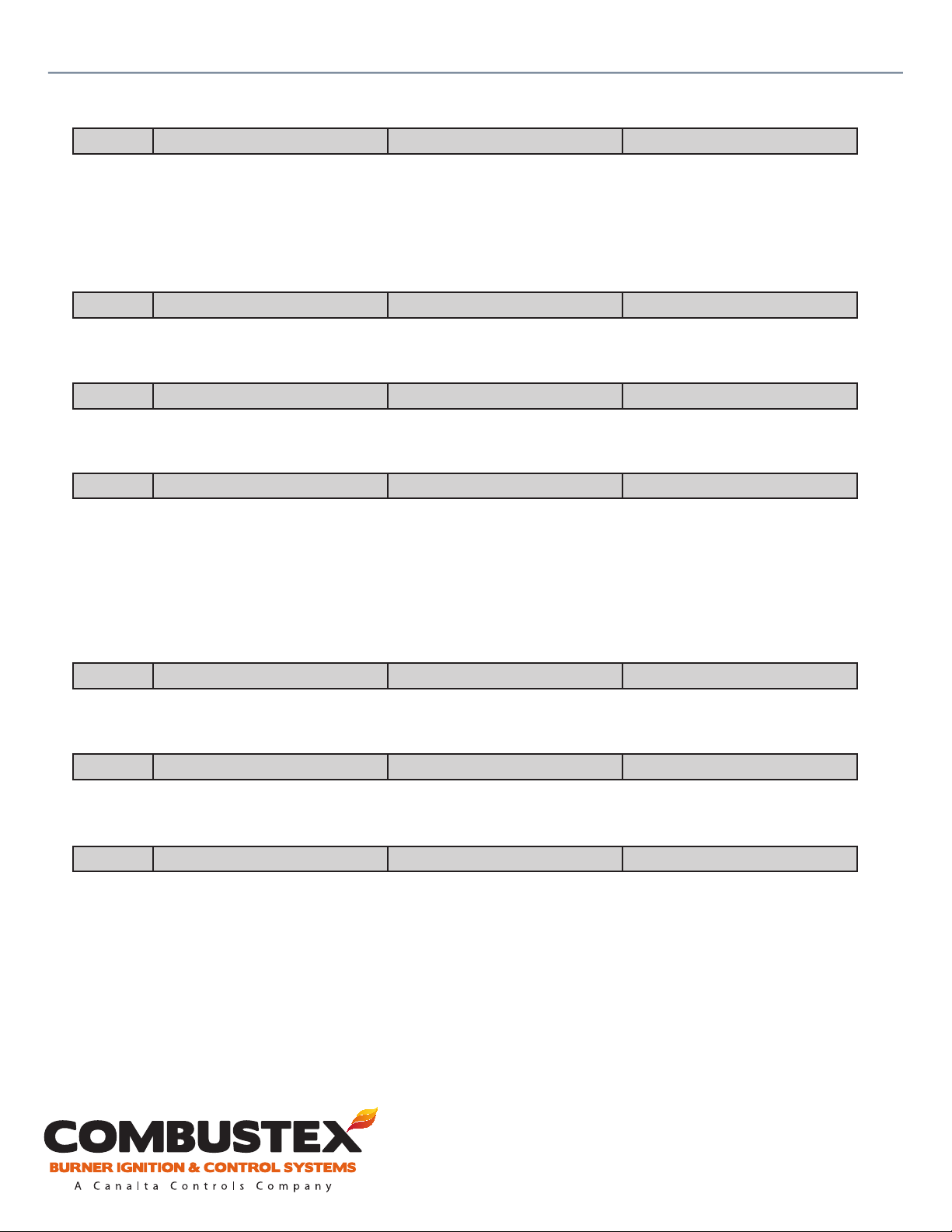
34 Control Output Mode
Steady / Latching Pulse
This sets the output mode for the pilot and main solenoid valves.
• Steady: Provides a constant voltage to the solenoid when on.
• Latching Pulse: For specialized solenoids only. This selection provides a pulse to open (latch) the
solenoid, and another pulse to close (unlatch) the solenoid.
35 Remote Set Point I/P
Yes / No
Enables the set point input options on page two of the controller display. See section 2.4.
36 Remote Temp. Indicate Out
Yes / No
Enables the spare 4-20mA output to indicate bath temperature remotely.
37 Backlight
Steady On / O / Light Activated / Timed
This congures the behaviour of the controller display backlight.
• Steady On: Backlight stays on whenever the controller is powered up.
• O: Backlight is disabled.
• Light Activated: Backlight will turn on when the ambient light becomes dim.
• Timed: Backlight will turn on when any key is pressed and will remain on for approx. ve minutes.
38 Audio
Yes / No
This feature is not available in this version of the BMS software.
39 New Access Code
0 - 9999
This sets the ‘USER’ password to a user-dened value. Factory default is set to ‘1313’. See section 2.2.
40 R.F. Filter
0 - 1000
When a sharp RF spike is detected, the BMS-2000 will hold the previous setting. The typical setting is 20,
which gives approx. ve seconds of hold time.
For operational, technical or installation assistance, please contact us.
Phone: 403.342.4494 | Web: www.canaltaow.com
Call Us Toll Free: 1-855-226-2582
Page 26

Combustex BMS-2000 [5.03] Operations Manual - 3. CONFIGURATION
24
of 42
41 L.P. Filter (Pilot, Spare #1)
0 - 9999
This sets the lter, which mathematically smooths noisy signals for the pilot and spare thermocouple
input.
42 L.P. Filter (Pilot, Spare #2)
0 - 9999
This sets the lter, which mathematically smooths noisy signals for the bath and process thermocouple
input.
43 Modbus Address
0 - 247
This sets the device ID when using the modbus computer interface.
For operational, technical or installation assistance, please contact us.
Phone: 403.342.4494 | Web: www.canaltaow.com
Call Us Toll Free: 1-855-226-2582
Page 27

Combustex BMS-2000 [5.03] Operations Manual - 4. CALIBRATION
CALIBRATION
4.1 OVERVIEW
NOTE: This page is password protected and cannot be accessed while the BMS is in normal operation.
See section 2.2.
The BMS-2000 calibration menu is accessed by depressing the ‘CALIB.’ button on the controller’s keypad.
Ensure that proper calibration equipment is available before entering the calibration menu. Once
ready to calibrate, enter the conguration menu and ensure that the ‘RF Filter’ is set to a value of 0.
This will disable the lter and allow the BMS to respond more quickly to the changing of signals during
calibration.
Once in the calibration menu:
25
of 42
1. Use the and buttons to scroll through the menu items.
2. Scroll to the ‘Zero’ value of the input to be calibrated.
3. Press the ‘ACK’ key. A ashing cursor allows the value to be changed.
4. Use the ‘SELECT ITEM’ key to move the cursor.
5. Use the and buttons to change the displayed value.
6. Match the displayed value with the known forced input value from the calibration equipment.
7. Press the ‘ACK’ key to save this calibration point.
8. Repeat the procedure for the ‘Span’ value.
9. To exit from the conguration menu, press ‘PAGE SCROLL’.
Notes:
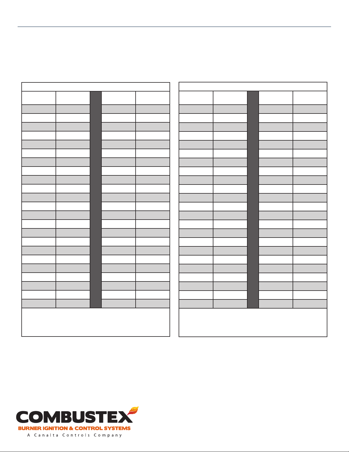
• Thermocouple inputs require a millivoltage signal. Refer to the Thermocouple Reference Chart for
millivoltage values for type K thermocouples.
• When forcing (sending) T/C signals, compensate for reference junction temperature by subtracting
the mV value that would represent reference junction temperature from your forced mV values.
• 4-20mA inputs require a current signal input for calibration.
• The voltage input is calibrated by varying the voltage supplied to the BMS.
• 4-20mA outputs do not require a known input or output. Simply assign the ‘Zero’ and ‘Span’ values
in the calibration menu.
For operational, technical or installation assistance, please contact us.
Phone: 403.342.4494 | Web: www.canaltaow.com
Call Us Toll Free: 1-855-226-2582
Page 28

Combustex BMS-2000 [5.03] Operations Manual - 4. CALIBRATION
4.2 CALIBRATION MENU ITEMS
Inputs Range Allowed / Type of Signal
Pilot #1 Flame Zero Value 0 - 800°C (32 - 1472°F) / Type K Thermocouple Input
Pilot #1 Flame Span Value 0 - 800°C (32 - 1472°F) / Type K Thermocouple Input
Pilot #2 Flame Zero Value 0 - 800°C (32 - 1472°F) / Type K Thermocouple Input
Pilot #2 Flame Span Value 0 - 800°C (32 - 1472°F) / Type K Thermocouple Input
Bath Temp. Zero Value 0 - 800°C (32 - 1472°F) / Type K Thermocouple Input
Bath Temp. Span Value 0 - 800°C (32 - 1472°F) / Type K Thermocouple Input
Spare #1 Temp. Zero Value 0 - 800°C (32 - 1472°F) / Type K Thermocouple Input
Spare #1 Temp. Span Value 0 - 800°C (32 - 1472°F) / Type K Thermocouple Input
Spare #2 Temp. Zero Value 0 - 800°C (32 - 1472°F) / Type K Thermocouple Input
Spare #2 Temp. Span Value 0 - 800°C (32 - 1472°F) / Type K Thermocouple Input
Remote Set Point Zero (4ma) 0 - 800°C (32 - 1472°F) / Current Loop Input
Remote Set Point Span (20ma) 0 - 800°C (32 - 1472°F) / Current Loop Input
Spare Analog #1 Zero (4ma) 0 - 100% / Current Loop Input
Spare Analog #1 Span (20ma) 0 - 100% / Current Loop Input
Power Input (Low) 10 - 30 Volts / Voltage Input
Power Input (High) 10 - 30 Volts / Voltage Input
26
of 42
Outputs Range Allowed / Type of Signal
Bath Temp. Zero (4ma) 0 - 800°C (32 - 1472°F) / Current Loop Output
Bath Temp. Span (20ma) 0 - 800°C (32 - 1472°F) / Current Loop Output
Process Temp. Zero (4ma) 0 - 800°C (32 - 1472°F) / Current Loop Output
Process Temp. Span (20ma) 0 - 800°C (32 - 1472°F) / Current Loop Output
Note: Bath and Spare #2 Thermocouple Inputs are range selectable on the front board via DIP switches.
• Low Range allows inputs 0 - 150°C (32 - 302°F)
• Medium Range allows inputs 0 - 300°C (32 - 572°F)
• High Range allows inputs 0 - 800°C (32 - 1472°F)
For operational, technical or installation assistance, please contact us.
Phone: 403.342.4494 | Web: www.canaltaow.com
Call Us Toll Free: 1-855-226-2582
Page 29
Combustex BMS-2000 [5.03] Operations Manual - 4. CALIBRATION
4.3 THERMOCOUPLE REFERENCE CHART
27
of 42
THERMOCOUPLE TO MILLIVOLTAGE REFERENCE CHART
Thermocouple
Temp. (°C)
0 0.000 380 15.552
10 0.397 400 16.395
20 0.798 420 17.241
25 1.000 440 18.088
30 1.203 460 18.938
40 1.611 480 19.788
50 2.022 500 20.640
60 2.436 520 21.493
80 3.266 540 22.346
100 4.095 560 23.198
120 4.919 580 24.050
140 5.733 600 24.092
160 6.539 620 25.751
180 7.338 640 26.599
200 8.137 660 27.445
220 8.938 680 28.128
240 9.745 700 28.288
260 10.560 720 29.165
280 11.381 740 30.799
300 12.207 760 31.629
320 13.039 780 32.455
340 13.874 800 33.277
360 14.712
Type K
Voltage (mV)
Thermocouple
Temp. (°C)
Voltage (mV)
Type K
THERMOCOUPLE TO MILLIVOLTAGE REFERENCE CHART
Thermocouple
Temp. (°F)
32 0.000 640 13.782
40 0.176 680 14.713
50 0.397 720 15.647
60 0.619 760 16.585
70 0.843 800 17.526
80 1.068 840 18.469
90 1.294 880 19.414
100 1.521 920 20.360
120 1.977 960 21.308
140 2.436 1000 22.255
160 2.897 1040 23.203
180 3.359 1080 24.149
200 3.820 1120 25.094
240 4.738 1160 26.037
280 5.644 1200 26.978
320 6.540 1240 27.915
360 7.429 1280 28.849
400 8.316 1320 29.780
440 9.208 1360 30.706
480 10.108 1400 31.628
520 11.017 1440 32.545
560 11.933 1480 33.458
600 12.855
Type K
Voltage (mV)
Thermocouple
Temp. (°F)
Voltage (mV)
Type K
°C
°F
For operational, technical or installation assistance, please contact us.
Phone: 403.342.4494 | Web: www.canaltaow.com
Call Us Toll Free: 1-855-226-2582
Page 30

Combustex BMS-2000 [5.03] Operations Manual - 5. INSTALLATION
INSTALLATION
5.1 OVERVIEW
Controller Location
The BMS-2000 is CSA certied for Class 1, Division 2 Groups A, B, C and D hazardous locations. It is also
rated NEMA Type 4x and can be readily installed outdoors. The BMS is ideally located away from the
ame arrestor in an area not subject to extreme heat and vibration. The distance between the BMS unit
and pilot / ignitor assembly can be up to 50 feet at specied interconnecting wiring guages (see below).
Greater distances can be achieved if the wiring gauge is increased and line resistance does not exceed
0.5Ω. When installed on the outside wall of a building, care must be taken to protect the controller from
heavy runo or falling snow and ice. Particular attention must be paid to Class 1, Div. 1 building vents
which limit the location of Div. 2 rated equipment to within 1.5 meters of such openings.
Conduit Entry
The preferred location for conduit entry is the bottom of the BMS-2000 enclosure. Top entry is also
available, but care must be taken to ensure a weather tight seal through the use of a Myers Hub or other
approved CEC wiring methods.
28
of 42
Wiring Methods
1. Use rigid steel or aluminum conduit.
2. Interconnecting wiring:
• Power to the BMS and interconnecting power to the igniter should be (minimum) gauge 14 Belden
or equivalent with shields tied to the BMS end only. Note: If the distance between the BMS and pilot
/ ingitor assembly is greater than 50 feet, increase the wire gauge to achieve line resistance no greater
than 0.5Ω.
• All other digital and analog inputs should be (minimum) gauge 16 or equivalent.
3. Interconnecting wiring between thermocouples and the BMS must be type K extension grade
thermocouple wire with a shield. Tie shields to the BMS end only.
4. Ground the negative of the power input to the chassis ground.
Solenoids
The pilot and main solenoids must be rated for the same voltage as supplied to the BMS, and approved
for the area classication where they are being installed. Solenoid valves must be congured in
accordance with the instrumentation P&ID drawings contained in this manual (see pp. 31 - 35). All tubing
should be a minimum of 3/8” and properly supported using raceway or tubing clips.
Power Supply Requirements
The BMS-2000 requires a 10 - 30 volt DC supply free of spikes and interference. The power source
should be rated for at least 3 Amperes for a typical system. This requirement will be higher if additional
solenoids or other loads are driven from the BMS outputs.
For operational, technical or installation assistance, please contact us.
Phone: 403.342.4494 | Web: www.canaltaow.com
Call Us Toll Free: 1-855-226-2582
Page 31

Combustex BMS-2000 [5.03] Operations Manual - 5. INSTALLATION
5.2 ANALOG INPUT CONNECTIONS
Five type K thermocouple inputs are available:
1. Pilot Flame #1 (N/A if using contact input for ame sensing)
2. Pilot Flame #2 (N/A if using contact input for ame sensing)
3. Spare #1
4. Spare #2
5. Bath
Two 4-20mA inputs are available:
1. Remote Bath Temperature Set Point
2. Spare Analog #1
5.3 DIGITAL INPUT CONNECTIONS
Twelve dry contact inputs are available:
1. Remote Stop
2. Remote Start
3. Flame Detection #1 Input
4. Flame Detection #2 Input
5. Low Bath Level
6. Aux. High Temp.
7. Low Fuel Pressure Burner #1
8. Low Fuel Pressure Burner #2
9. Proof of Closure Burner #1
10. Proof of Closure Burner #2
11. High Fuel Pressure Burner #1
12. High Fuel Pressure Burner #2
29
of 42
Note: All digital inputs require a dry set of contacts for operation. The BMS
provides excitation power (5 Volts) for the contact. Any attempt to provide
the input with an external supply may result in damage to the controller.
5.4 ANALOG OUTPUT CONNECTIONS
Two 4-20mA outputs are available:
1. Proportional Control Output
2. Remote Bath Temperature Indication
Note: These outputs are powered directly from the BMS controller. Any
attempt to power externally will damage the controller.
For operational, technical or installation assistance, please contact us.
Phone: 403.342.4494 | Web: www.canaltaow.com
Call Us Toll Free: 1-855-226-2582
Page 32
Combustex BMS-2000 [5.03] Operations Manual - 5. INSTALLATION
5.5 DIGITAL OUTPUT CONNECTIONS
Sixteen digital outputs are available:
1. Igniter #1
2. Igniter #2
3. Status #1
4. Status #2
5. Pilot #1
6. Pilot #2
7. Main #1 SD Valve
8. Main #2 SD Valve
9. Main #1 ON/OFF Control
10. Main #2 ON/OFF Control
11. Purge Blower
12. Spare #1 (not utilized in this software version)
13. Spare #2 (not utilized in this software version)
14. Spare #3 - SD indication (ON when there are no shutdowns active; OFF when there are any
shutdowns active)
15. Pilot #1 Unlatch (available upon request - for latching solenoids only)
16. Pilot #2 Unlatch (available upon request - for latching solenoids only)
30
of 42
Note: These outputs are powered directly from the BMS controller. Any
attempt to power externally will damage the controller. All outputs will
be at the same potential as the supplied power to the BMS.
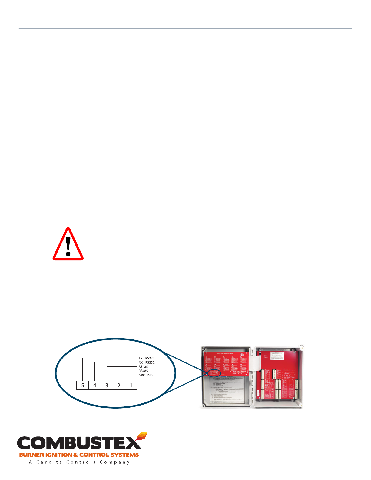
5.6 MODBUS CONNECTIONS
Five Modbus terminals are located on the front circuit board of the Combustex BMS controller: two
terminals for Modbus RS232, two terminals for Modbus RS485, and one for ground. Ensure power to the
BMS controller is o before terminating wires. A Modbus Map is available by contacting Combustex
directly.
For operational, technical or installation assistance, please contact us.
Phone: 403.342.4494 | Web: www.canaltaow.com
Call Us Toll Free: 1-855-226-2582
Page 33
Combustex BMS-2000 [5.03] Operations Manual - 5. INSTALLATION
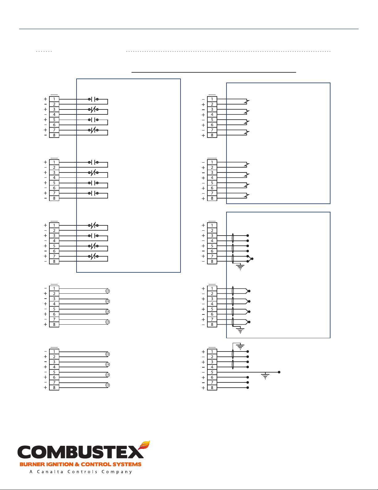
DIAGRAMS
BMS 2000 Wiring Diagram - Version 5.03 / 5.032
31
of 42
FIELD DEVICES
TS1 TS8
TS2 TS10
TS4 TS5
Note: jumper out N/C eld devices not in use.
FLAME DETECTION (BURNER #2)
PROOF OF CLOSURE (BURNER #2)
REMOTE START
REMOTE STOP
LOW BATH LEVEL S/D
AUX. HIGH BATH TEMP. S/D
FLAME DETECTION (BURNER #1)
LOW FUEL PRESSURE S/D (BURNER #1)
HIGH FUEL PRESSURE S/D (BURNER #2)
LOW FUEL PRESSURE S/D (BURNER #2)
HIGH FUEL PRESSURE S/D (BURNER #1)
PROOF OF CLOSURE (BURNER #1)
SOLENOID OUTPUTS
SOV. MAIN #1 SHUTDOWN VALVE
SOV. MAIN #1 (TEMP. CONTROL ON / OFF)
SOV. UNLATCH PILOT #1
SOV. PILOT #1
SOV. MAIN #2 SHUTDOWN VALVE
SOV. MAIN #2 (TEMP. CONTROL ON / OFF)
SOV. UNLATCH PILOT #2
SOV. PILOT #2
ANALOG INPUTS
NOT USED
SPARE 4-20mA INPUT
REMOTE SETPOINT 4-20mA INPUT
BATH TEMP. THERMOCOUPLE
TS7 TS6
BLOWER OUTPUT
SPARE OUTPUT #3
IGNITER #1 OUTPUT POWER
FLAME STATUS #1
TS9 TS3
SPARE OUTPUT #1
SPARE OUTPUT #2
IGNITER #2 OUTPUT POWER
FLAME STATUS #2
Notes
1. 4-20mA outputs are current sourcing.
2. Thermocouples (+) yellow (-) red.
3. Shielded thermocouple ext. wire must be
used for accurate readings.
4. 4-20mA inputs are current sinking (loop powered).
5. TS7, TS8, TS9 and TS10 are INTERNALLY powered outputs.
6. TS6 1&2 are dedicated to PROCESS in software version 5.032.
For operational, technical or installation assistance, please contact us.
Phone: 403.342.4494 | Web: www.canaltaow.com
SPARE #2 THERMOCOUPLE (see note 6)
PILOT #2 THERMOCOUPLE
SPARE #1 THERMOCOUPLE
PILOT #1 THERMOCOUPLE
REMOTE TEMP. INDIC. 4-20mA OUTPUT
PROP. TEMP. CONTROL 4-20mA OUTPUT
AUX. POWER OUTPUT
POWER INPUT (12-30 VDC)
Call Us Toll Free: 1-855-226-2582
Page 34
Combustex BMS-2000 [5.03] Operations Manual - 5. INSTALLATION
TS5 7&8
TS6 5&6
BURNER FLAME STATUS OUTPUT
REMOTE BATH TEMPERATURE OUTPUT
REMOTE BATH TEMPERATURE SETPOINT INPUT
TS7 7&8, TS9 7&8
TS3 1&2
TS5 5&6
12 TO 30 VDC POWER SUPPLY
REMOTE START/STOP INPUT
TS1 5&6, 7&8
TS3 7&8
TS6 1&2
TS2 1&2
7&8
1&2
7&8
TS2 3&4
TS2
TS8
TS4
T/C
(Dedicated to Process
on Version 5.032)
CONFIGURABLE ADDERS
(see manual section 3.2)
T/C
SPARE #1 TEMP.
SPARE #2 TEMP.
LLSD
BATH LOW LEVEL
Indication, Temp. Control & SD
THERMOCOUPLE INPUTS
T/C
BATH TEMP.
SAFETY INTERLOCKS
HTSD
AUX. BATH
HIGH TEMP.
CLEAN, DRY
FUEL GAS
REQUIREMENTS
MAIN BURNER
SET AS PER
(if required)
Relief Valve
LPSD
#1
of 42
32
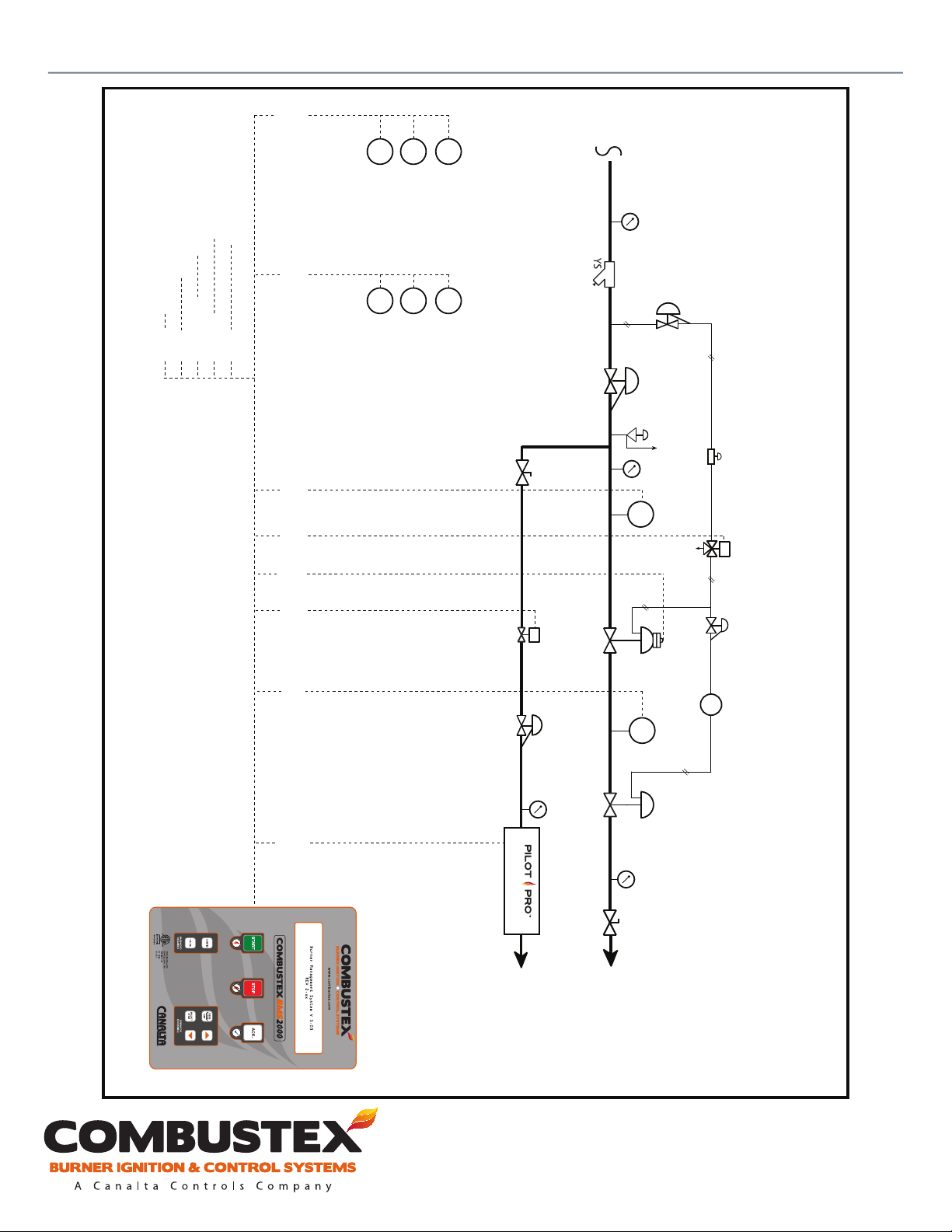
Combustex BMS-2000 P&ID-A
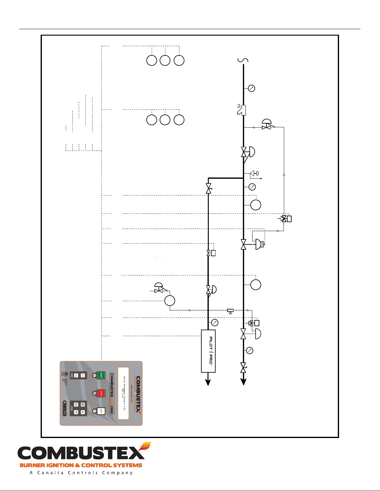
Single Burner Piping Conguration with POC Valve.
External Temperature Control.
Filter regulator set at
SSOV requirements
Speed Control
Valve
Solenoid
SSOV
E
Drawing complies with CSA B149.3-10 up to 5 MM Btuh.
Class 1 Div. 2 Hazardous Location
TS7 6
7&8
5&6
TS3 5&6
TS8
TS4
TS2 5&6
REQUIREMENTS
PILOT BURNER
See Note B
E
SET AS PER
Igniter / Pilot / FFSD
PILOT #1
Pilot Valve
Solenoid
See Note A
MAIN #1
CONTROL VALVE
REQUIREMENTS
Proof of Closure
SSOV with
HPSD
#1
Main Control
Valve
SET AS PER
T/C
Main Temp
Controller
Note A: Safety Shutdown Valve with POC compliant with
CSA ANSI Z21.21 / CGA 6.5CI / CGA 3.9 / FM7412
Note B: Z21.21 / CSA 6.5
For operational, technical or installation assistance, please contact us.
Phone: 403.342.4494 | Web: www.canaltaow.com
Call Us Toll Free: 1-855-226-2582
Page 35
Combustex BMS-2000 [5.03] Operations Manual - 5. INSTALLATION
TS5 7&8
TS6 5&6
BURNER FLAME STATUS OUTPUT
REMOTE BATH TEMPERATURE OUTPUT
REMOTE BATH TEMPERATURE SETPOINT INPUT
TS7 7&8, TS9 7&8
TS3 1&2
TS5 5&6
12 TO 30 VDC POWER SUPPLY
REMOTE START/STOP INPUT
TS1 5&6, 7&8
TS3 7&8
TS6 1&2
TS2 1&2
7&8
1&2
7&8
TS2 3&4
TS2
TS8
TS4
T/C
(Dedicated to Process
on Version 5.032)
CONFIGURABLE ADDERS
(see manual section 3.2)
T/C
SPARE #1 TEMP.
SPARE #2 TEMP.
LLSD
BATH LOW LEVEL
Indication, Temp. Control & SD
THERMOCOUPLE INPUTS
T/C
BATH TEMP.
SAFETY INTERLOCKS
HTSD
AUX. BATH
HIGH TEMP.
CLEAN, DRY
FUEL GAS
REQUIREMENTS
MAIN BURNER
SET AS PER
(if required)
Relief Valve
LPSD
#1
of 42
33
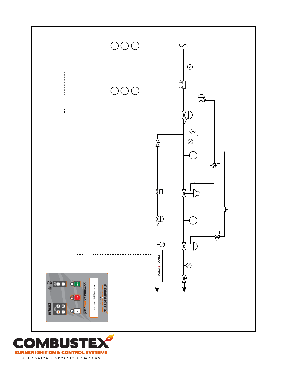
Combustex BMS-2000 P&ID-B
Single Burner Piping Conguration with
POC and ON/OFF Temperature Control
via BMS-2000.
Filter regulator set at
SSOV requirements
E
Solenoid
SD Valve
Drawing complies with CSA B149.3-10 up to 5 MM Btuh.
Class 1 Div. 2 Hazardous Location
TS7 6
7&8
5&6
3&4
TS3 5&6
TS8
TS4
TS8
TS2 5&6
REQUIREMENTS
PILOT BURNER
See Note B
E
SET AS PER
Igniter / Pilot / FFSD
PILOT #1
Pilot Valve
Solenoid
See Note A
MAIN #1
Proof of Closure
SSOV with
Speed Control
Valve
HPSD
#1
E
Main Control
Valve
ON/OFF Control
Valve Solenoid
Note A: Safety Shutdown Valve with POC compliant with
CSA ANSI Z21.21 / CGA 6.5CI / CGA 3.9 / FM7412
Note B: Z21.21 / CSA 6.5
For operational, technical or installation assistance, please contact us.
Phone: 403.342.4494 | Web: www.canaltaow.com
Call Us Toll Free: 1-855-226-2582
Page 36
Combustex BMS-2000 [5.03] Operations Manual - 5. INSTALLATION
TS5 7&8
TS6 5&6
BURNER FLAME STATUS OUTPUT
REMOTE BATH TEMPERATURE OUTPUT
REMOTE BATH TEMPERATURE SETPOINT INPUT
TS7 7&8, TS9 7&8
TS3 1&2
TS5 5&6
12 TO 30 VDC POWER SUPPLY
REMOTE START/STOP INPUT
TS1 5&6, 7&8
TS3 7&8
TS6 1&2
TS2 1&2
7&8
1&2
7&8
7&8
TS2 3&4
TS2
TS8
TS4
TS8
T/C
(Dedicated to Process
on Version 5.032)
CONFIGURABLE ADDERS
(see manual section 3.2)
T/C
SPARE #1 TEMP.
SPARE #2 TEMP.
LLSD
BATH LOW LEVEL
Indication, Temp. Control & SD
THERMOCOUPLE INPUTS
T/C
BATH TEMP.
SAFETY INTERLOCKS
HTSD
AUX. BATH
HIGH TEMP.
See Note B
of 42
34
CLEAN, DRY
FUEL GAS
Filter regulator set at
SSOV requirements
REQUIREMENTS
MAIN BURNER
SET AS PER
(if required)
Relief Valve
LPSD
#1
Solenoid
SSOV
E
Proof of Closure
SSOV with
Pilot Valve
Solenoid
E
See Note A
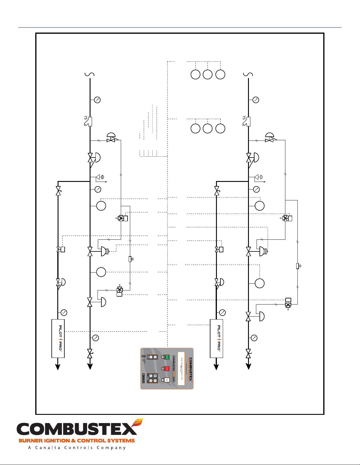
Single Burner Piping Conguration with POC Valve.
PID Temperature Control via BMS-2000.
Combustex BMS-2000 P&ID-C
Drawing complies with CSA B149.3-10 up to 5 MM Btuh.
Class 1 Div. 2 Hazardous Location.
TS7 6
5&6
3&4
3&4
TS3 5&6
TS4
TS3
TS8
TS2 5&6
REQUIREMENTS
PILOT BURNER
A/S
I/P
SET AS PER
Control
Speed
Valve
Igniter / Pilot / FFSD
PILOT #1
#1
MAIN #1
HPSD
E
Main Control
Valve
Note A: Safety Shutdown Valve with POC compliant with
CSA ANSI Z21.21 / CGA 6.5CI / CGA 3.9 / FM7412
Note B: Z21.21 / CSA 6.5
For operational, technical or installation assistance, please contact us.
Phone: 403.342.4494 | Web: www.canaltaow.com
Call Us Toll Free: 1-855-226-2582
Page 37
Combustex BMS-2000 [5.03] Operations Manual - 5. INSTALLATION
TS5 7&8
TS6 5&6
CLEAN, DRY
FUEL GAS
REQUIREMENTS
MAIN BURNER
SET AS PER
12 TO 30 VDC POWER SUPPLY
REMOTE START/STOP INPUT
BURNER FLAME STATUS OUTPUT
REMOTE BATH TEMPERATURE OUTPUT
REMOTE BATH TEMPERATURE SETPOINT INPUT
Filter regulator set at
SSOV requirements
TS7 7&8, TS9 7&8
TS1 5&6, 7&8
TS3 7&8
TS3 1&2
TS5 5&6
TS6 1&2
TS2 1&2
TS2 3&4
T/C
(Dedicated to Process
on Version 5.032)
CONFIGURABLE ADDERS
(see manual section 3.2)
SPARE #2 TEMP.
T/C
SPARE #1 TEMP.
LLSD
BATH LOW LEVEL
of 42
35
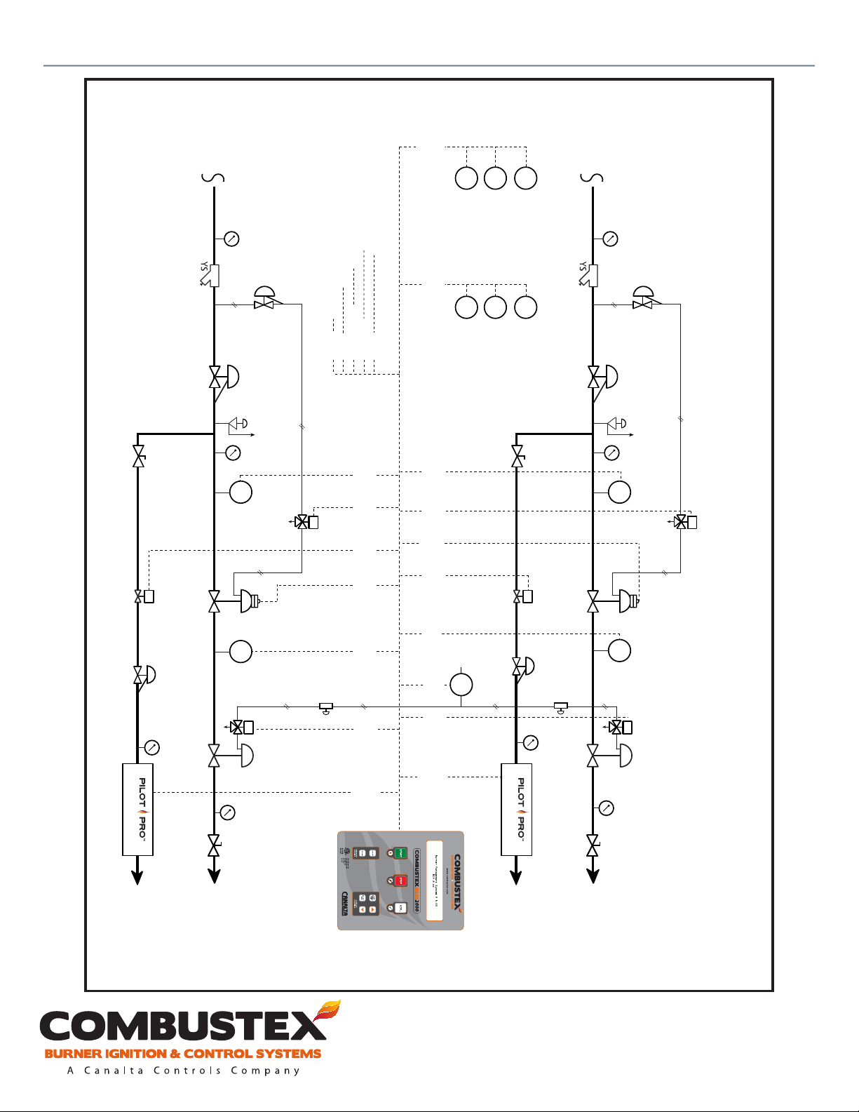
Combustex BMS-2000 P&ID-D
Dual Burner Independent Parallel
Piping Conguration with POC Valve.
ON/OFF Temp. Control via BMS-2000.
Indication, Temp. Control & SD
THERMOCOUPLE INPUTS
CLEAN, DRY
FUEL GAS
T/C
BATH TEMP.
Filter regulator set at
SSOV requirements
SAFETY INTERLOCKS
HTSD
AUX. BATH
HIGH TEMP.
REQUIREMENTS
MAIN BURNER
SET AS PER
Drawing complies with CSA B149.3-10 up to 5 MM Btuh.
See Note B
E
Igniter / Pilot / FFSD
Pilot Valve
Solenoid
REQUIREMENTS
PILOT BURNER
SET AS PER
Proof of Closure
SSOV with
(if required)
Relief Valve
7&8
1&2
TS2
TS8
3&4
TS4
LPSD
#2
1&2
TS10
E
Solenoid
SSOV
TS10
7&8
3&4
TS1
Main Temp. ON/OFF
Speed Control
Valve
1&2
TS4
TS10
3&4
TS1 1&2
TS3 5&6
TS9 6
Note A
See
HPSD
#2
E
Main Control
Valve
Control Solenoid
TS7 6
7&8
7&8
5&6
3&4
TS4
TS8
TS4
TS8
TS2 5&6
TS3 5&6
REQUIREMENTS
PILOT BURNER
See Note B
E
SET AS PER
Igniter / Pilot / FFSD
Pilot Valve
Solenoid
See Note A
(if required)
Relief Valve
LPSD
#1
E
Solenoid
SSOV
Proof of Closure
SSOV with
Speed Control
Valve
HPSD
#1
E
Note A: Safety Shutdown Valve with POC compliant with
CSA ANSI Z21.21 / CGA 6.5CI / CGA 3.9 / FM7412
Main Control
Valve
Main Temp. ON/OFF
Control Solenoid
Note B: Z21.21 / CSA 6.5
Class 1 Div. 2 Hazardous Location.
PILOT #2
MAIN #2
PILOT #1
MAIN #1
For operational, technical or installation assistance, please contact us.
Phone: 403.342.4494 | Web: www.canaltaow.com
Call Us Toll Free: 1-855-226-2582
Page 38
Combustex BMS-2000 [5.03] Operations Manual - 5. INSTALLATION
TS5 7&8
TS6 5&6
CLEAN, DRY
FUEL GAS
12 TO 30 VDC POWER SUPPLY
REMOTE START/STOP INPUT
BURNER FLAME STATUS OUTPUT
REMOTE BATH TEMPERATURE OUTPUT
REMOTE BATH TEMPERATURE SETPOINT INPUT
TS6 1&2
on Version 5.032)
T/C
SPARE #2 TEMP.
(Dedicated to Process
T/C
SPARE #1 TEMP.
T/C
of 42
36
Combustex BMS-2000 P&ID-E
Dual Burner Independent Parallel Piping
Conguration with POC Valve. PID Temp.
Control via BMS-2000.
Indication, Temp. Control & SD
THERMOCOUPLE INPUTS
BATH TEMP.
CLEAN, DRY
FUEL GAS
REQUIREMENTS
MAIN BURNER
(if required)
Relief Valve
SSOV requirements
SET AS PER
Proof of Closure
SSOV with
Filter regulator set at
E
Solenoid
SSOV
Filter regulator set at
SSOV requirements
TS2 3&4
TS2 1&2
SAFETY INTERLOCKS
HTSD
CONFIGURABLE ADDERS
(see manual section 3.2)
A/S
I/P
LLSD
BATH LOW LEVEL
REQUIREMENTS
PILOT BURNER
See Note B
SET AS PER
AUX. BATH
HIGH TEMP.
LPSD
#1
Pilot Valve
Solenoid
E
Valve
Control
Speed
See Note A
HPSD
#1
TS7 7&8, TS9 7&8
TS1 5&6, 7&8
TS3 7&8
TS3 1&2
TS5 5&6
REQUIREMENTS
MAIN BURNER
SET AS PER
(if required)
Relief Valve
7&8
5&6
1&2
7&8
7&8
3&4
TS2
TS8
TS4
TS8
TS4
TS3
3&4
TS4
LPSD
#2
Solenoid
SSOV
E
See Note B
E
Pilot Valve
Solenoid
REQUIREMENTS
PILOT BURNER
Proof of Closure
SET AS PER
SSOV with
Note A
See
HPSD
#2
Control
Valve
Speed
1&2
7&8
3&4
1&2
TS10
TS10
TS1
TS4
Drawing complies with CSA B149.3-10 up to 5 MM Btuh.
Class 1 Div. 2 Hazardous Location.
Igniter / Pilot / FFSD
PILOT #2
MAIN #2
3&4
TS7 6
TS8
TS2 5&6
TS3 5&6
Igniter / Pilot / FFSD
PILOT #1
MAIN #1
E
Control Valve
Main Temp.
Note A: Safety Shutdown Valve with POC compliant with
CSA ANSI Z21.21 / CGA 6.5CI / CGA 3.9 / FM7412
Note B: Z21.21 / CSA 6.5
TS10
TS9 6
3&4
TS1 1&2
TS3 5&6
E
Control Valve
Main Temp.
For operational, technical or installation assistance, please contact us.
Phone: 403.342.4494 | Web: www.canaltaow.com
Call Us Toll Free: 1-855-226-2582
Page 39

Combustex BMS-2000 [5.03] Operations Manual - 6. TROUBLESHOOTING
TROUBLESHOOTING SHUTDOWN CONDITIONS
6.1 ERROR MESSAGES AND SHUTDOWN CONDITIONS
System function errors resulting from equipment failure or faulty wiring (including BMS hardware) are
indicated in one of two ways:
• An error message is displayed on the BMS 2000 LCD screen (e.g. Flame #1 T/C Failed indicating a
faulty thermocouple on pilot #1).
• A shutdown cannot be cleared from the annunciation screen despite having it’s condition satised
(e.g. Bath High Temp. cannot be cleared when actual bath temperature falls below the preset
HTSD value).
Note: All shutdowns are factory set to YES by default. If a specic shutdown is not required, it must
be manually set to NO in the Conguration Menu (see Section 3 pp. 15 - 24). If a specic shutdown is
congured to YES but no eld device device is terminated to its slot at the BMS controller, a shutdown
message will be displayed and the controller will NOT be permitted to START.
37
of 42
DI Test 01 is a generic procedure to test the function of all discrete inputs on the BMS controller, and
should be used if the recommended corrective actions described below fail to remedy the problem.
To perform the test, disconnect both wires from the DI terminal (refer to the BMS 2000 wiring diagram
p. 31). If the specic shutdown is enabled in the conguration menu, the DI will be activated. Use a
wire to jumper the +/- terminal of the DI. Note: Power down the controller when removing wires and
installing jumper wire. With acknowledgement, the S/D should automatically clear from the shutdown
list on display Page 1. The test result is classied as positive if the DI functions as above. If the DI fails to
perform as above, the test result is classied as negative and may indicate a hardware malfunction on
the BMS controller. Contact Combustex for assistance, service or warranty.
NO.
BMS ERROR MESSAGE /
SHUTDOWN
1 Auxiliary Bath High Temp
2 Bath High Temp.
ERROR SOURCE /
DESCRIPTION
Bath Aux. Contact sensor
indicating high temperature of
vessel.
(BMS TS2 #3-4)
Bath T/C probe indicating
High Temperature Alarm. Bath
temp from T/C at TS5 #7-8 has
exceeded the HTSD value.
CORRECTIVE ACTION
If S/D is activated and there is no indication by other sensors that alarm
level was crossed, check wiring of DI Bath HTSD. If wiring is OK, check
bath temperature sensor’s contact switch. Replace if switch is faulty.
Otherwise, wait for Bath Temperature to fall below preset alarm level and
shutdown should be satised. If problem persists, perform DI Test 01.
If bath temperature (indicated by a reference gauge) falls below
preset HTSD value (set in CONFIG menu) and S/D cannot be cleared,
check wiring and condition of Bath T/C with a mV or T/C calibrator. If
T/C is faulty, replace with new one. If T/C and wiring is OK, perform a
eld calibration to Bath T/C input. If proper tools are not accessible or
problems persist, contact Combustex for repair request.
For operational, technical or installation assistance, please contact us.
Phone: 403.342.4494 | Web: www.canaltaow.com
Call Us Toll Free: 1-855-226-2582
Page 40

Combustex BMS-2000 [5.03] Operations Manual - 6. TROUBLESHOOTING
38
of 42
NO.
BMS ERROR MESSAGE /
SHUTDOWN
3 Bath T/C Failed
4 Flame 1 Failed On 1st Level
5
6
Flame 1 Failed On 2nd
Level
Flame 1 Failed During
Relite
Flame 1 O
7
or
Flame 1 Failed to Ignite
ERROR SOURCE /
DESCRIPTION
Bath T/C sensor indicates OPEN
thermocouple state.
Pilot 1 failed to reach 1st level
(usually 250˚C) within Trial for
Ignition Timer value
Pilot 1 failed to reach 2nd level
(usually 450˚C) within Flame T/C
2nd Level Timer value.
Pilot 1 failed to ignite within all
preset relite attempts.
Contact Type ame detection
on pilot 1 failed to conrm
ame within Trial for Ignition
Timer value.
CORRECTIVE ACTION
Message indicates open/faulty thermocouple on T/C input TS5 #7-8.
Check wiring of thermocouple to BMS and ensure wires are securely
and properly terminated. Check T/C condition with mV meter or T/C
calibrator. If T/C is faulty, replace with new one. If wiring and T/C are OK,
disconnect T/C and jumper terminals. If S/D is still active with terminal
jumpered, contact Combustex for replacment of T/C modules.
Verify thermocouple condition with mV source or T/C calibrator. If T/C
is faulty, replace with new one. If T/C is in good condition, check the
position of the T/C in the pilot head to ensure it is getting good exposure
to ame. Also, ensure pilot assembly is correctly installed and aligned
with main burner. Note: Flame T/C levels and timers may need to be
adjusted slightly to best suit pilot and burner conditions.
Verify thermocouple condition with mV source or T/C calibrator. If T/C
is faulty, replace with new one. If T/C is in good condition, check the
position of the T/C in the pilot head to ensure it is getting good exposure
to ame. Also, ensure pilot assembly is correctly installed and aligned
with main burner. NOTE: Flame T/C levels and timers may need to be
adjusted slightly to best suit pilot and burner conditions.
Verify thermocouple condition with mV source or T/C calibrator. If T/C
is faulty, replace with new one. If T/C is in good condition, check the
position of the T/C in the pilot head to ensure it is getting good exposure
to ame. Also, ensure pilot assembly is correctly installed and aligned
with main burner. Verify spark plug is producing strong spark. If spark
plug is faulty, replace with new one.
Check wiring of Ignition Module or Flame Scanner back to BMS at TS2 #5-
6. Refer to Model 900 or 550 manual for Ignition Module to BMS wiring
schematic. If wiring is OK, check condition of pilot ignition module
for burner 1 or 3rd party ame sensing equipment (Flame Scanner).
Also check condition and installation of all pilot assembly equipment.
Replace any faulty piece of equipment as required. Contact Combustex if
problems persist.
8 Flame 1 T/C Failed
9 Flame 2 Failed On 1st Level
10
Flame 2 Failed On 2nd
Level
Pilot 1 Flame T/C sensor
indicates OPEN thermocouple
state.
Pilot 2 failed to reach 1st level
(usually 250˚C) within Trial for
Ignition Timer value
Pilot 2 failed to reach 2nd level
(usually 450˚C) within Flame T/C
2nd Level Timer value.
Phone: 403.342.4494 | Web: www.canaltaow.com
Message indicates open/faulty thermocouple on T/C input TS6 #7-8.
Check wiring of thermocouple to BMS and ensure wires are securely
and properly terminated. Check T/C condition with mV meter or T/C
calibrator. If T/C is faulty, replace with new one. If wiring and T/C are OK,
disconnect T/C and jumper terminals. If S/D is still active with terminal
jumpered, contact Combustex for replacement of T/C modules.
Verify thermocouple condition with mV source or T/C calibrator. If T/C
is faulty, replace with new one. If T/C is in good condition, check the
position of the T/C in the pilot head to ensure it is getting good exposure
to ame. Also, ensure pilot assembly is correctly installed and aligned
with main burner. NOTE: Flame T/C levels and timers may need to be
adjusted slightly to best suit pilot and burner conditions.
Verify thermocouple condition with mV source or T/C calibrator. If T/C
is faulty, replace with new one. If T/C is in good condition, check the
position of the T/C in the pilot head to ensure it is getting good exposure
to ame. Also, ensure pilot assembly is correctly installed and aligned
with main burner. NOTE: Flame T/C levels and timers may need to be
adjusted slightly to best suit pilot and burner conditions.
For operational, technical or installation assistance, please contact us.
Call Us Toll Free: 1-855-226-2582
Page 41

Combustex BMS-2000 [5.03] Operations Manual - 6. TROUBLESHOOTING
39
of 42
NO.
11
BMS ERROR MESSAGE /
SHUTDOWN
Flame 2 Failed During
Relite
Flame 2 O
12
or
Flame 2 Failed to Ignite
13 Flame 2 T/C Failed
14 High Fuel Press. 1
ERROR SOURCE /
DESCRIPTION
Pilot 2 failed to ignite within all
preset relite attempts.
Contact Type ame detection
on pilot 2 failed to conrm
ame within Trial for Ignition
Timer value.
Pilot 2 Flame T/C sensor
indicates OPEN thermocouple
state.
Gas supply signal for Main
Burner 1 indicating high input
fuel pressure.
(BMS TS4 #5-6)
CORRECTIVE ACTION
Verify thermocouple condition with mV source or T/C calibrator. If T/C
is faulty, replace with new one. If T/C is in good condition, check the
position of the T/C in the pilot head to ensure it is getting good exposure
to ame. Also, ensure pilot assembly is correctly installed and aligned
with main burner. Verify spark plug is producing strong spark. If spark
plug is faulty, replace with new one.
Check wiring of Ignition Module or Flame Scanner back to BMS at TS1 #1-
2. Refer to Model 900 or 550 manual for Ignition Module to BMS wiring
schematic. If wiring is OK, check condition of pilot ignition module
for burner #1 or 3rd party ame sensing equipment (Flame Scanner).
Also check condition and installation of all pilot assembly equipment.
Replace any faulty piece of equipment as required. Contact Combustex if
problems persist.
Message indicates open/faulty thermocouple on T/C input TS6 #3-4.
Check wiring of thermocouple to BMS and ensure wires are securely
and properly terminated. Check T/C condition with mV meter or T/C
calibrator. If T/C is faulty, replace with new one. If wiring and T/C are OK,
disconnect T/C and jumper terminals. If S/D is still active with terminal
jumpered, contact Combustex for replacment of T/C modules.
Check wiring of High Fuel Pressure Switch. If wiring is OK, check High
Fuel Pressure sensor. Replace sensor if faulty. If problem persists,
perform DI Test 01.
15 High Fuel Press. 2
16 Local Manual S/D
17 Low Bath Level
18 Low Fuel Press. 1
Gas supply signal for Main
Burner 2 indicating high input
fuel pressure.
(BMS TS4 #1-2)
Local STOP Key on BMS 2000
was pressed to S/D unit from
Normal Operation.
Level sensor indicating Low
Bath Level.
(BMS TS2 #1-2)
Gas supply signal for Main
Burner 1 indicating low input
fuel pressure.
(BMS TS2 #7-8)
Check wiring of High Fuel Pressure Switch. If wiring is OK, check High
Fuel Pressure sensor. Replace sensor if faulty. If problem persists,
perform DI Test 01.
If STOP key was NOT hit and Local Manual S/D cannot be cleared from
annunciation screen, call Combustex. Problem could be a faulty keypad
or main front board circuitry.
Check wiring of Low Bath sensor to BMS. If wiring is OK, check Low level
sensor contact. Replace Low level sensor if contact is faulty. If problem
persists, perform DI Test 01.
Check wiring of Low Fuel Pressure Switch. If wiring is OK, check Low Fuel
Pressure sensor. Replace sensor if faulty. If problem persists, perform DI
Test 01.
For operational, technical or installation assistance, please contact us.
Phone: 403.342.4494 | Web: www.canaltaow.com
Call Us Toll Free: 1-855-226-2582
Page 42

Combustex BMS-2000 [5.03] Operations Manual - 6. TROUBLESHOOTING
40
of 42
NO.
BMS ERROR MESSAGE /
SHUTDOWN
19 Low Fuel Press. 2
20 Low Input Voltage
21 P.O.Closure 1 Failed
22 P.O.Closure 2 Failed
ERROR SOURCE /
DESCRIPTION
Gas supply signal for Main
Burner 2 indicating low input
fuel pressure.
(BMS TS4 #3-4)
BMS-2000 Input Power Voltage
fell below preset value.
Proof of closure contact failed
to close, indicating OPEN status
of main P.O.C. valve 1.
(BMS TS4 #7-8)
Proof of Closure contact failed
to close, indicating Open status
of Main P.O.C. valve 2.
(BMS TS1 #3-4)
CORRECTIVE ACTION
Check wiring of Low Fuel Pressure Switch. If wiring is OK, check Low Fuel
Pressure sensor. Replace sensor if faulty. If problem persists, perform DI
Test 01.
Press ACK key to see if error clears. If still active, measure input voltage at
TS3 # 7-8 and conrm that it’s value matches the Supply Voltage reading
on display Page 4 of the BMS. If values do not coincide, a calibration is
required. Contact Combustex. Refer to CONFIG menu for preset Low
Power S/D value and if supply voltage is below set value, check power
supply to controller for problem. If input has been re-calibrated and
voltage is still below set value, contact Combustex for controller repair.
Check wiring of P.O.C. limit switch to the BMS and the condition of the
switch itself. If wiring is OK, check P.O.C. contact function. Replace limit
switch if contact is faulty. If problem persists, perform DI Test 01.
Check wiring of P.O.C. Limit Switch to the BMS and the condition of the
switch itself. If wiring is OK, check P.O.C. contact function. Replace Limit
Switch if contact is faulty. If problem persists, perform DI Test 01.
23 Remote Shutdown
24 Spare 1 High Temp.
25 Spare 1 T/C Failed
26 Spare 2 High Temp.
Remote S/D discrete input
signal is activated from remote
location.
(BMS TS1 #7-8)
Spare T/C 1 input indicates T/C
reading has exceeded preset
S/D temp
Spare 1 T/C sensor indicates
OPEN thermocouple state.
Spare T/C 2 input indicates T/C
reading has exceeded preset
S/D temp
If Remote S/D indicated but not issued by Remote Stop source, check
wiring of DI and verify the source of REMOTE STOP is NORMALLY CLOSED
and not triggered. If problem persists, perform DI Test 01.
If Spare #1 temperature (indicated by a reference gauge) falls below
preset HTSD value (set in CONFIG menu) and S/D cannot be cleared,
check wiring and condition of Spare #1 T/C with a mV or T/C calibrator. If
T/C is faulty, replace with new one. If T/C and wiring is OK, perform a eld
calibration to Spare #1 T/C input. If proper tools are not accessible or
problems persist, contact Combustex for repair request.
Message indicates open/faulty thermocouple on T/C input TS6 #5-6.
Check wiring of thermocouple to BMS and ensure wires are securely
and properly terminated. Check T/C condition with mV meter or T/C
calibrator. If T/C is faulty, replace with new one. If wiring and T/C are OK,
disconnect T/C and jumper terminals. If S/D is still active with terminal
jumpered, contact Combustex for replacement of T/C modules.
If Spare 2 temperature (indicated by a reference gauge) falls below
preset HTSD value (set in CONFIG menu) and S/D cannot be cleared,
check wiring and condition of Spare #2 T/C with a mV or T/C calibrator. If
T/C is faulty, replace with new one. If T/C and wiring is OK, perform a eld
calibration to Spare #2 T/C input. If proper tools are not accessible or
problems persist, contact Combustex for repair request.
For operational, technical or installation assistance, please contact us.
Phone: 403.342.4494 | Web: www.canaltaow.com
Call Us Toll Free: 1-855-226-2582
Page 43

Combustex BMS-2000 [5.03] Operations Manual - 6. TROUBLESHOOTING
41
of 42
NO.
BMS ERROR MESSAGE /
SHUTDOWN
27 Spare 2 T/C Failed
28 Spare Analog #1 S/D
ERROR SOURCE /
DESCRIPTION
Spare 2 T/C sensor indicates
OPEN thermocouple state.
Spare 4-20 mA analog input
value has exceeded preset S/D
limit.
(BMS TS5 #3-4)
CORRECTIVE ACTION
Message indicates open/faulty thermocouple on T/C input TS6 #1-2.
Check wiring of thermocouple to BMS and ensure wires are securely
and properly terminated. Check T/C condition with mV meter or T/C
calibrator. If T/C is faulty, replace with new one. If wiring and T/C are OK,
disconnect T/C and jumper terminals. If S/D is still active with terminal
jumpered, contact Combustex for replacment of T/C modules.
If analog signal drops back below the preset S/D level and error still
does not clear (after ACK is pressed), check the wiring of the 4-20 mA
transmitter back to the BMS. If wiring is OK, check proper functioning
of transmitter and calibration of BMS by measuring the 4-20 signal with
mA meter and compare to BMS reading. If required, perform a eld
calibration. If proper tools are not accessible and/or problems still persist,
contact Combustex for repair request.
For operational, technical or installation assistance, please contact us.
Phone: 403.342.4494 | Web: www.canaltaow.com
Call Us Toll Free: 1-855-226-2582
Page 44

Combustex BMS-2000 [5.03] Operations Manual
NOTES
42
of 42
Combustex BMS 2000 Manual Online (.indd/.pdf)
THIS MANUAL REV 2.4 - 10/2013
The “Canalta,” “Combustex Burner Ignition & Control Systems” and “Pilot Pro” names and logos are trademarks of Canalta Controls Ltd. All other trademarks are
the property of their respective owners.
Due to Canalta’s commitment to quality and innovation, all product designs, specications and information materials, including the contents of this publication,
are subject to change without notice. Responsibility for the proper selection, maintenance and use of any product remains with the customer. SAFETY FIRST.
© 2011 Canalta Controls Ltd. All rights reserved. Unauthorized reproduction in whole or in part is prohibited.
For operational, technical or installation assistance, please contact us.
Phone: 403.342.4494 | Web: www.canaltaow.com
Call Us Toll Free: 1-855-226-2582
 Loading...