

CAN FC Series, FC1336, FC1345, FC1347, FC1348 Installation, Use And Maintenance Instruction Manual
...
CAN S.r.l.
Via Nazionale 65,
25080 - Puegnago del Garda (BS) ITALY
T. +39 0365 555909
F. +39 0365 651822
info@cansrl.com
www.cansrl.com
DE
HANDBUCH FÜR INSTALLATION,
GEBRAUCH UND WARTUNG
serie FC
IT
MANUALE DI ISTRUZIONI
INSTALLAZIONE-USO-MANUTENZIONE
EN
INSTALLATION, USE AND
MAINTENANCE INSTRUCTION MANUAL
FR
MANUEL D’INSTRUCTIONS D’INSTALLATIOND’UTILISATION-ET D’ENTRETIEN
ES
MANUAL DE INSTRUCCIONES
INSTALACIÓN-USO-MANTENIMIENTO
2
ENGLISHENGLISH
GAS HOB UNITS WITH GLASS RECESSED LID ▪ FC series
Thank you for having purchased our cooking device CAN S.r.l.
This is a quality appliance, made in Italy, that reliably and safely accompanies you throughout your vacation
and leisure time, always guaranteeing high level performance.
Installation and use of the device are simple and straightforward.
Please read this manual carefully: this will allow you to install and use your appliance correctly, always
keeping it in perfect working order for years. The instructions in this booklet only apply to the Country
of destination. The gas supply systems must meet current national standards.
The following symbols have been used in the manual to make it easier to read:
SAFETY-RELATED WARNINGS FOR INSTALLERS AND USERS
Failure to comply with these warnings can cause material damage and jeopardise operation of
the appliance.
GENERAL INFORMATION
Additional information for installers and users.
CAN S.r.l., as the manufacturer of the appliance, reserves the right to make changes to its products and to
this manual considered appropriate, without being obliged to give prior notice. The drawings, installation
diagrams and tables in the manual must be considered as guides and exclusively for explanatory purposes.
CAN S.r.l. prohibits fully or partially copying or reproducing the contents of this manual or forwarding it to
third parties without the consent of the Manufacturer.
revision index
Edition 07/2018
Revision 00
3
ENGLISH
DECLARATION OF CONFORMITY
CAN S.r.l.
Italian company with headquarters at:
Via Nazionale, 65 – 25080, Puegnago del Garda ( BS) – ITALY
VAT NO. 03607980988 – REA BS548442
DECLARES THAT
the products called
GAS HOB UNITS WITH GLASS RECESSED LID
FC SERIES – TYPE: FC133X – FC134X – FC135X
Meet all the essential requirements of the GAD Directive – 2009/142/EEC of 30/11/2009 and also the
subsequent GAR regulation - 2016/426/EU of 09/03/2016, as well as the following regulations:
• EC regulation 1935/2004
• EU Regulation no.65/2014 – “ENERGY LABEL”
• EU Regulation no.66/2014 – “ECODESIGN”
Our devices are also manufactured in compliance with all relevant harmonised technical standards for the
sector, in particular:
• EN 30-1-1: 2008 + A3 02/2013
• EN 30-2-1: 2015
We hereby declare that all the products of the FC SERIES are built according to the specifications of the
appliances described in:
TYPE TEST CERTIFICATE no. 51CO4387 issued by IMQ S.p.a.
as notified body, with identification number 0051
The undersigned, Lorenzo Bellini, as director of the company CAN S.r.l., assumes full responsibility for the
truthfulness of the declarations herein.
Puegnago del Garda, 26/03/2018
Signature: Lorenzo Bellini
4
ENGLISH
TABLE OF CONTENTS
TECHNICAL DATA SHEET: FC1336 6
TECHNICAL DATA SHEET: FC1337 8
TECHNICAL DATA SHEET: FC1343 10
TECHNICAL DATA SHEET: FC1344 12
TECHNICAL DATA SHEET: FC1345 14
TECHNICAL DATA SHEET: FC1347 16
TECHNICAL DATA SHEET: FC1348 18
TECHNICAL DATA SHEET: FC1349 20
TECHNICAL DATA SHEET: FC1350 22
TECHNICAL DATA SHEET: FC1352 24
GENERAL SAFETY WARNINGS 26
INTENDED USE 27
OBLIGATIONS AND PROHIBITIONS 27
OBLIGATIONS 27
PROHIBITIONS 27
IDENTIFICATION OF THE APPLIANCE 28
RECEIVING THE APPLIANCE 29
CONTROL AND HANDLING 29
DISPOSING OF THE PACKAGING 29
GENERAL PRELIMINARY INFORMATION 26
5
ENGLISHENGLISH
Installation, use and maintenance instruction manual ▪ Ed. 07/2018 Rev. 00
INSTRUCTIONS FOR THE INSTALLER 30
INSTALLATION ROOM 30
FEATURES OF INSTALLATION ROOM 30
FLUE GAS EXHAUST 30
INSTALLATION ON SUPPORT STRUCTURE 31
RECESSED HOLE 31
SAFETY DISTANCES 32
POSITIONING THE APPLIANCE 33
GAS CONNECTION 34
GAS CATEGORIES 34
CONNECTION PIPE REQUIREMENTS 34
GAS CONNECTION PROCEDURE 35
ELECTRICAL CONNECTION (ONLY FOR E VERSION) 35
TROUBLESHOOTING AFTER INSTALLATION 36
INSTRUCTIONS FOR USE 37
SPARE PARTS 54
DESCRIPTION 37
SAFETY WARNINGS DURING USE 48
USE 48
LIGHTING THE BURNERS 49
ADJUSTING THE FLAME 50
COOKING OR WARMING UP FOOD 50
SWITCHING OFF THE BURNER 51
OPERATING FAULTS 51
WHAT TO DO IN CASE OF MALFUNCTIONING 51
MAINTENANCE AND CLEANING 52
LONG IDLE PERIODS 53
WASTE DISPOSAL 53
WARRANTY 53
SPARE PARTS - FC1336 54
SPARE PARTS - FC1337 55
SPARE PARTS - FC1343 56
SPARE PARTS - FC1344 56
SPARE PARTS - FC1345 57
SPARE PARTS - FC1347 58
SPARE PARTS - FC1348 59
SPARE PARTS - FC1349 59
SPARE PARTS - FC1350 60
SPARE PARTS - FC1352 61
6
ENGLISHENGLISH
GAS HOB UNITS WITH GLASS RECESSED LID ▪ FC series
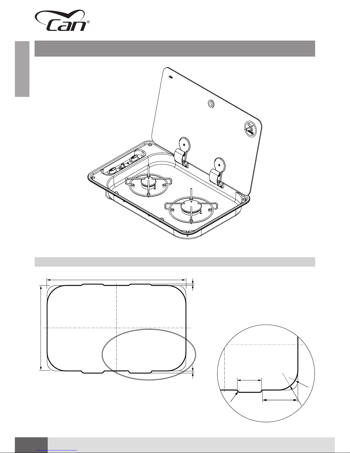
TECHNICAL DATA SHEET: FC1336
RECESSED HOLE FC1336
C
A
B
5 mm
8 mm
Detail C
85 mm
R10
128 mm
R32
R70
7
ENGLISHENGLISH
Installation, use and maintenance instruction manual ▪ Ed. 07/2018 Rev. 00
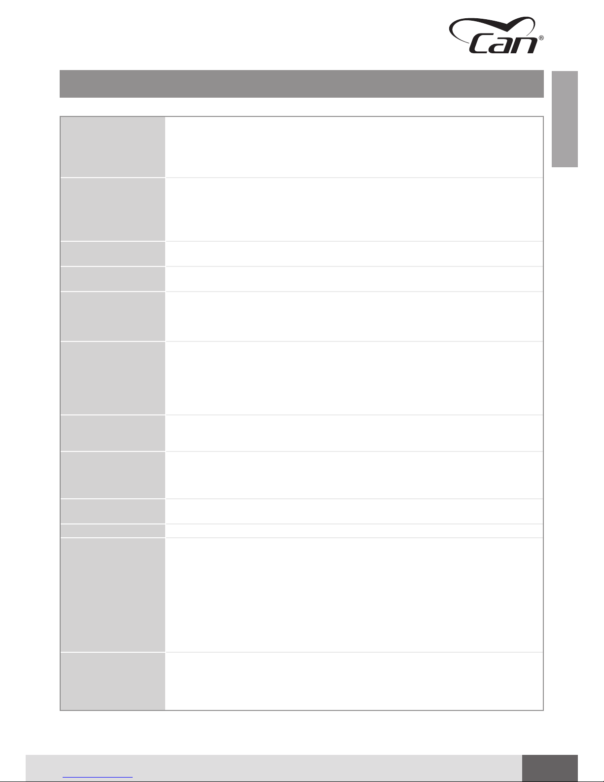
Dimensions Width 530 mm
Depth 340 mm
Height 48 mm (hob area)
105 mm (valves area)
Weight 3.6 kg
Hob Unit
(straight valves with
bypass Ø 0.36 mm)
Nominal values:
1 x AUXILIARY burner (AUX)
Pn 1.00 kW – injector ø 0.50 mm – consumption 72.50 g/h
1 x SEMIRAPID burner (SR):
Pn 1.75 kW – injector ø 0.65 mm – consumption 127.0 g/h
Device Class
(EN 30-1-1 4.3)
CLASS 3 – Recessed hob unit
Device Category
(EN 30-1-1 5.1.1.2)
CATEGORY I
Admitted Gases
family
(EN 437)
(EN 30-1-1 4.2.2.4)
GAS OF THE THIRD FAMILY
▪ I3 B/P
▪ I3+
Gas Supply CATEGORY I3 B/P
▪ Butane (G30) 30 mbar
▪ Propane (G31) 30 mbar
CATEGORY I3+
▪ Butane (G30) 28-30 mbar
▪ Propane (G31) 37 mbar
Electric Connection
(only for “E” version with
electronic lighting)
ELECTRIC CONNECTION IN EXTRA-LOW VOLTAGE - 12V / DC
Lighting ▪ S (MANUAL) – using external igniter
▪ E (ELECTRONIC) - 12 V/DC GENERATOR - SPARK - 10Kv @ 30 pF
▪ P (PIEZOELECTRIC) – Mechanically/manually operated piezoelectric igniter inserted
in hob unit
Gas Connection
Galvanised steel train: Ø 8 mm - 1 mm thick
smooth end piece (30 mm) suitable for press fitting connecting with rigid / flexible hose
Gas Capillaries Copper capillary pipes: Ø 4 mm – 0.5 mm thick
Materials ▪ Stainless steel AISI 304
▪ Glass
▪ Chromium-plated iron
▪ Zama
▪ Brass
▪ Copper
▪ Galvanised steel
▪ Aluminium alloy
▪ Enamelled steel
▪ Epdm
Declaration of
Conformity
(GAR 2016/426/EC)
▪ no asbestos
▪ suitable materials according to chapters 2 and 3 (Annex I)
▪ there are no welds with melting point lower than 450°C
▪ flammable materials were not used
▪ the materials are suitable according to the requirements of chapter 3.7
TECHNICAL DATA SHEET: FC1336
8
ENGLISHENGLISH
GAS HOB UNITS WITH GLASS RECESSED LID ▪ FC series
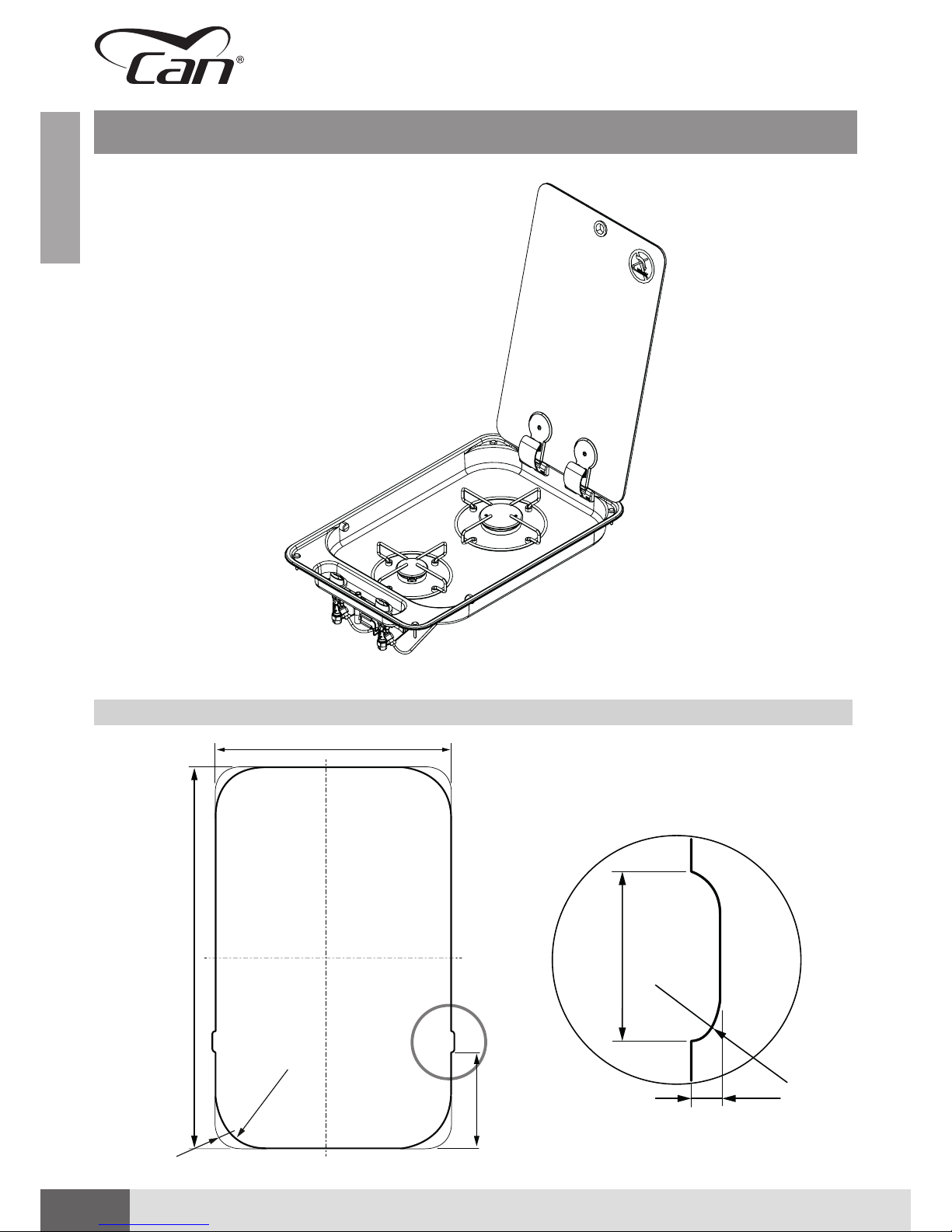
TECHNICAL DATA SHEET: FC1337
RECESSED HOLE FC1337
C
Detail C
A
B
R32
R70
130 mm
30 mm
R8
5

9
ENGLISHENGLISH
Installation, use and maintenance instruction manual ▪ Ed. 07/2018 Rev. 00
TECHNICAL DATA SHEET: FC1337
Dimensions Width 340 mm
Depth 530 mm
Height 48 mm (hob area)
105 mm (valves area)
Weight 3.8 kg
Hob Unit
(straight valves with
bypass Ø 0.36 mm)
Nominal values:
1 x AUXILIARY burner (AUX)
Pn 1.00 kW – injector ø 0.50 mm – consumption 72.50 g/h
1 x SEMIRAPID burner (SR):
Pn 1.75 kW – injector ø 0.65 mm – consumption 127.0 g/h
Device Class
(EN 30-1-1 4.3)
CLASS 3 – Recessed hob unit
Device Category
(EN 30-1-1 5.1.1.2)
CATEGORY I
Admitted Gases
family
(EN 437)
(EN 30-1-1 4.2.2.4)
GAS OF THE THIRD FAMILY
▪ I3 B/P
▪ I3+
Gas Supply CATEGORY I3 B/P
▪ Butane (G30) 30 mbar
▪ Propane (G31) 30 mbar
CATEGORY I3+
▪ Butane (G30) 28-30 mbar
▪ Propane (G31) 37 mbar
Electric Connection
(only for “E” version with
electronic lighting)
ELECTRIC CONNECTION IN EXTRA-LOW VOLTAGE - 12V / DC
Lighting ▪ S (MANUAL) – using external igniter
▪ E (ELECTRONIC) - 12 V/DC GENERATOR - SPARK - 10Kv @ 30 pF
▪ P (PIEZOELECTRIC) – Mechanically/manually operated piezoelectric igniter inserted
in hob unit
Gas Connection
Galvanised steel train: Ø 8 mm - 1 mm thick
smooth end piece (30 mm) suitable for press fitting connecting with rigid / flexible hose
Gas Capillaries Copper capillary pipes: Ø 4 mm – 0.5 mm thick
Materials ▪ Stainless steel AISI 304
▪ Glass
▪ Chromium-plated iron
▪ Zama
▪ Brass
▪ Copper
▪ Galvanised steel
▪ Aluminium alloy
▪ Enamelled steel
▪ Epdm
Declaration of
Conformity
(GAR 2016/426/EC)
▪ no asbestos
▪ suitable materials according to chapters 2 and 3 (Annex I)
▪ there are no welds with melting point lower than 450°C
▪ flammable materials were not used
▪ the materials are suitable according to the requirements of chapter 3.7

10
ENGLISHENGLISH
GAS HOB UNITS WITH GLASS RECESSED LID ▪ FC series
TECHNICAL DATA SHEET: FC1343
A
B
R32
R80
R340
RECESSED HOLE FC1343

11
ENGLISHENGLISH
Installation, use and maintenance instruction manual ▪ Ed. 07/2018 Rev. 00
TECHNICAL DATA SHEET: FC1343
Dimensions Width 480 mm
Depth 480 mm
Height 105 mm
Weight 5.5 kg
Hob Unit
(straight valves with
bypass Ø 0.36 mm)
Nominal values:
1 x AUXILIARY burner (AUX)
Pn 1.00 kW – injector ø 0.50 mm – consumption 72.50 g/h
2 x SEMIRAPID burner (SR):
Pn 1.75 kW – injector ø 0.65 mm – consumption 127.0 g/h
Device Class
(EN 30-1-1 4.3)
CLASS 3 – Recessed hob unit
Device Category
(EN 30-1-1 5.1.1.2)
CATEGORY I
Admitted Gases
family
(EN 437)
(EN 30-1-1 4.2.2.4)
GAS OF THE THIRD FAMILY
▪ I3 B/P
▪ I3+
Gas Supply CATEGORY I3 B/P
▪ Butane (G30) 30 mbar
▪ Propane (G31) 30 mbar
CATEGORY I3+
▪ Butane (G30) 28-30 mbar
▪ Propane (G31) 37 mbar
Electric Connection
(only for “E” version with
electronic lighting)
ELECTRIC CONNECTION IN EXTRA-LOW VOLTAGE - 12V / DC
Lighting ▪ S (MANUAL) – using external igniter
▪ E (ELECTRONIC) - 12 V/DC GENERATOR - SPARK - 10Kv @ 30 pF
Gas Connection
Galvanised steel train: Ø 8 mm - 1 mm thick
smooth end piece (30 mm) suitable for press fitting connecting with rigid / flexible hose
Gas Capillaries Copper capillary pipes: Ø 4 mm – 0.5 mm thick
Materials ▪ Stainless steel AISI 304
▪ Glass
▪ Chromium-plated iron
▪ Zama
▪ Brass
▪ Copper
▪ Galvanised steel
▪ Aluminium alloy
▪ Enamelled steel
▪ Epdm
Declaration of
Conformity
(GAR 2016/426/EC)
▪ no asbestos
▪ suitable materials according to chapters 2 and 3 (Annex I)
▪ there are no welds with melting point lower than 450°C
▪ flammable materials were not used
▪ the materials are suitable according to the requirements of chapter 3.7
12
ENGLISHENGLISH
GAS HOB UNITS WITH GLASS RECESSED LID ▪ FC series
TECHNICAL DATA SHEET: FC1344
RECESSED HOLE FC1344
A
B
R32
R80
R340

13
ENGLISHENGLISH
Installation, use and maintenance instruction manual ▪ Ed. 07/2018 Rev. 00
TECHNICAL DATA SHEET: FC1344
Dimensions Width 480 mm
Depth 480 mm
Height 105 mm
Weight 5.5 kg
Hob Unit
(straight valves with
bypass Ø 0.36 mm)
Nominal values:
1 x AUXILIARY burner (AUX)
Pn 1.00 kW – injector ø 0.50 mm – consumption 72.50 g/h
2 x SEMIRAPID burner (SR):
Pn 1.75 kW – injector ø 0.65 mm – consumption 127.0 g/h
Device Class
(EN 30-1-1 4.3)
CLASS 3 – Recessed hob unit
Device Category
(EN 30-1-1 5.1.1.2)
CATEGORY I
Admitted Gases
family
(EN 437)
(EN 30-1-1 4.2.2.4)
GAS OF THE THIRD FAMILY
▪ I3 B/P
▪ I3+
Gas Supply CATEGORY I3 B/P
▪ Butane (G30) 30 mbar
▪ Propane (G31) 30 mbar
CATEGORY I3+
▪ Butane (G30) 28-30 mbar
▪ Propane (G31) 37 mbar
Electric Connection
(only for “E” version with
electronic lighting)
ELECTRIC CONNECTION IN EXTRA-LOW VOLTAGE - 12V / DC
Lighting ▪ S (MANUAL) – using external igniter
▪ E (ELECTRONIC) - 12 V/DC GENERATOR - SPARK - 10Kv @ 30 pF
Gas Connection
Galvanised steel train: Ø 8 mm - 1 mm thick
smooth end piece (30 mm) suitable for press fitting connecting with rigid / flexible hose
Gas Capillaries Copper capillary pipes: Ø 4 mm – 0.5 mm thick
Materials ▪ Stainless steel AISI 304
▪ Glass
▪ Chromium-plated iron
▪ Zama
▪ Brass
▪ Copper
▪ Galvanised steel
▪ Aluminium alloy
▪ Enamelled steel
▪ Epdm
Declaration of
Conformity
(GAR 2016/426/EC)
▪ no asbestos
▪ suitable materials according to chapters 2 and 3 (Annex I)
▪ there are no welds with melting point lower than 450°C
▪ flammable materials were not used
▪ the materials are suitable according to the requirements of chapter 3.7
14
ENGLISHENGLISH
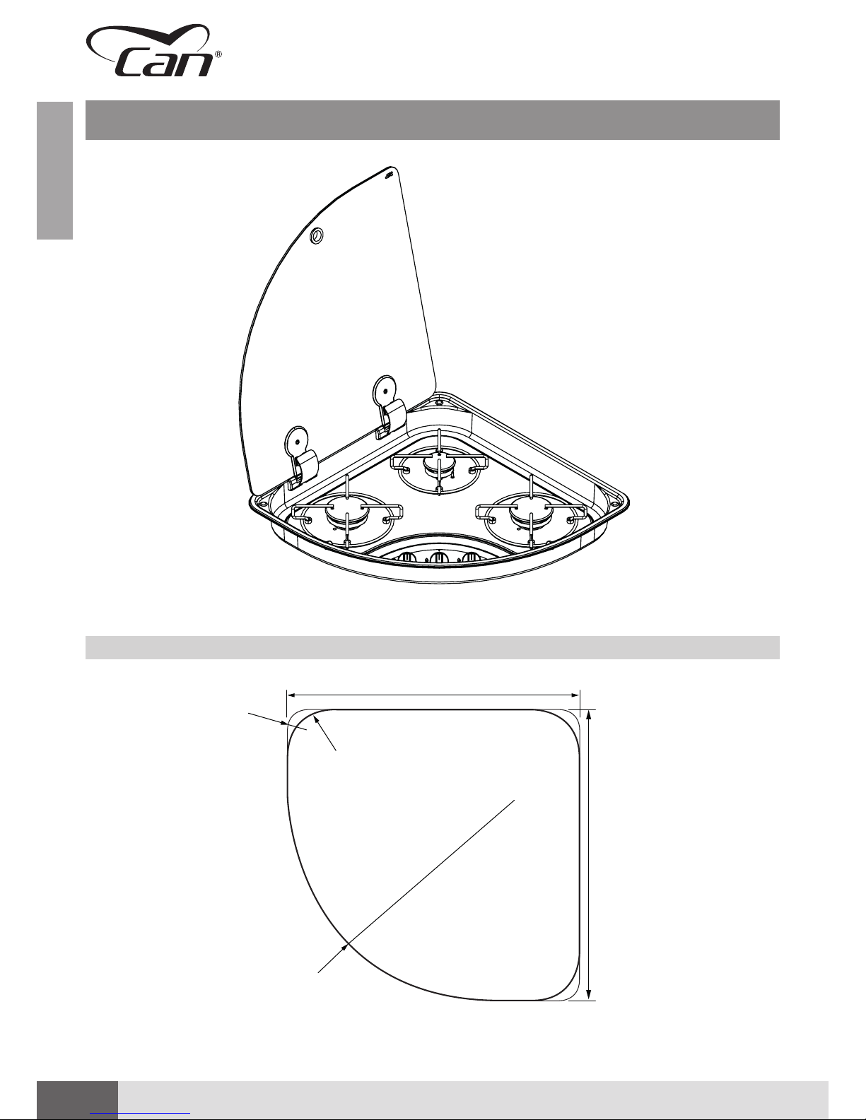
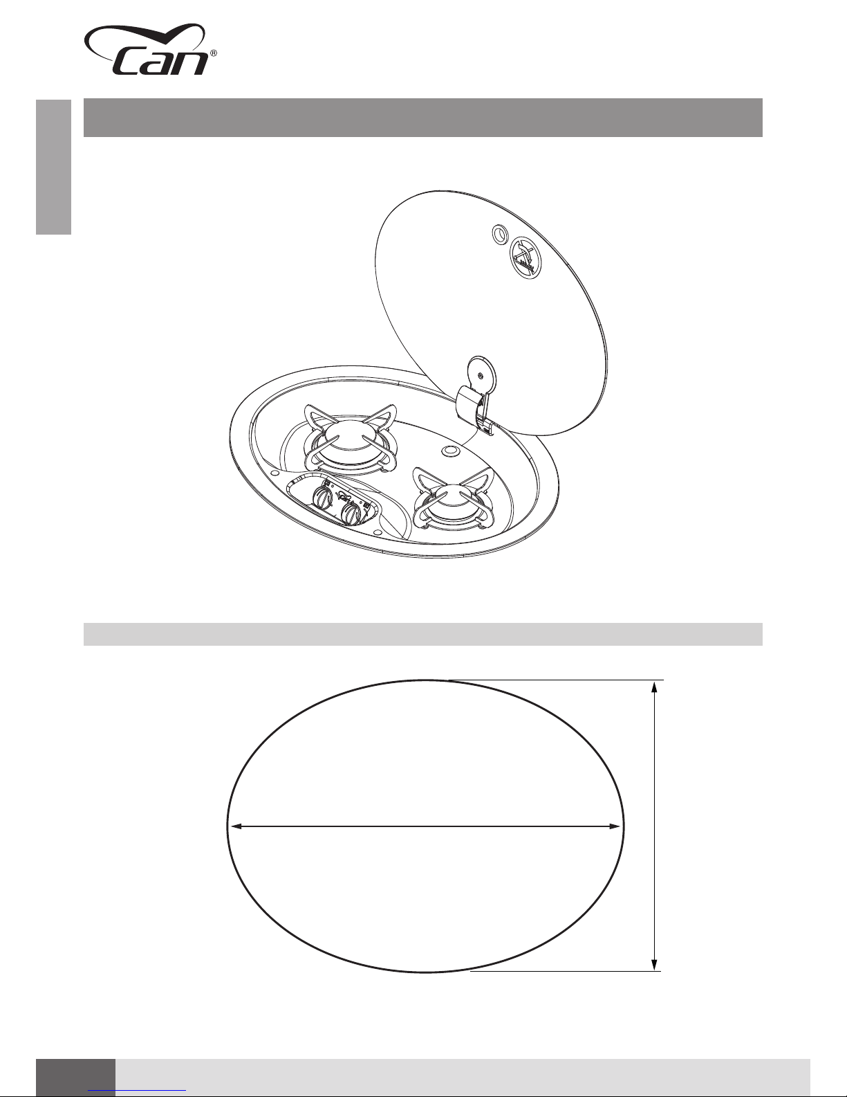
GAS HOB UNITS WITH GLASS RECESSED LID ▪ FC series
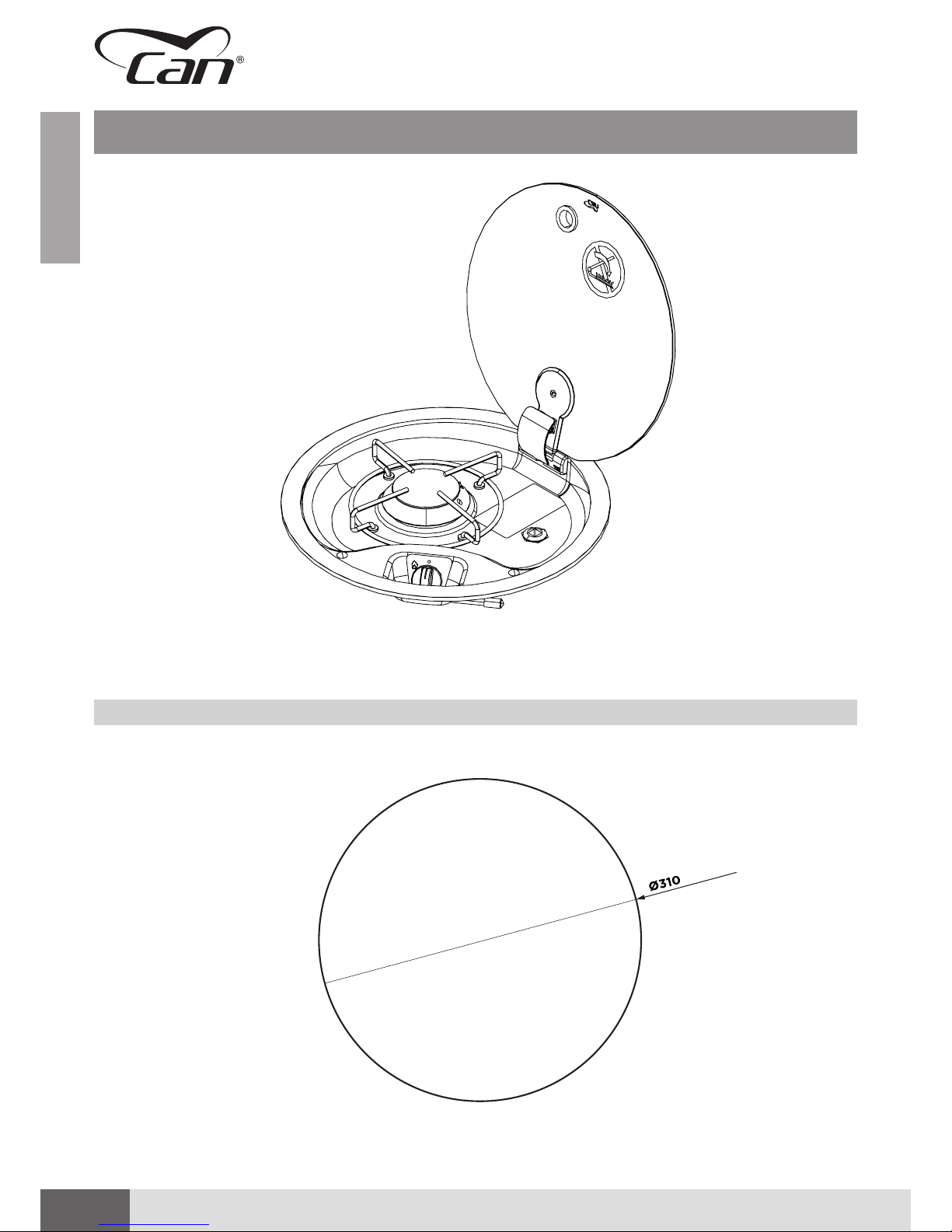
TECHNICAL DATA SHEET: FC1345
RECESSED HOLE FC1345
Please note: secured with adhesive.
15
ENGLISHENGLISH
Installation, use and maintenance instruction manual ▪ Ed. 07/2018 Rev. 00
TECHNICAL DATA SHEET: FC1345
Dimensions External Diameter (Ø) 340 mm
Height 80 mm
Weight 2.1 kg
Hob Unit
(straight valves with
bypass Ø 0.36 mm)
Nominal values:
1 x SEMIRAPID burner (SR):
Pn 2.00 kW – injector ø 0.70 mm – consumption 145.50 g/h
Device Class
(EN 30-1-1 4.3)
CLASS 3 – Recessed hob unit
Device Category
(EN 30-1-1 5.1.1.2)
CATEGORY I
Admitted Gases
family
(EN 437)
(EN 30-1-1 4.2.2.4)
GAS OF THE THIRD FAMILY
▪ I3 B/P
▪ I3+
Gas Supply CATEGORY I3 B/P
▪ Butane (G30) 30 mbar
▪ Propane (G31) 30 mbar
CATEGORY I3+
▪ Butane (G30) 28-30 mbar
▪ Propane (G31) 37 mbar
Electric Connection
(only for “E” version with
electronic lighting)
ELECTRIC CONNECTION IN EXTRA-LOW VOLTAGE - 12V / DC
Lighting ▪ S (MANUAL) – using external igniter
▪ E (ELECTRONIC) - 12 V/DC GENERATOR - SPARK - 10Kv @ 30 pF
Gas Connection Galvanised steel train: Ø 8 mm - 1 mm thick
smooth end piece (30 mm) suitable for press fitting connecting with rigid / flexible hose
Gas Capillaries Copper capillary pipes: Ø 4 mm – 0.5 mm thick
Materials ▪ Stainless steel AISI 304
▪ Glass
▪ Chromium-plated iron
▪ Zama
▪ Brass
▪ Copper
▪ Galvanised steel
▪ Aluminium alloy
▪ Enamelled steel
▪ Epdm
Declaration of
Conformity
(GAR 2016/426/EC)
▪ no asbestos
▪ suitable materials according to chapters 2 and 3 (Annex I)
▪ there are no welds with melting point lower than 450°C
▪ flammable materials were not used
▪ the materials are suitable according to the requirements of chapter 3.7

16
ENGLISHENGLISH
GAS HOB UNITS WITH GLASS RECESSED LID ▪ FC series
TECHNICAL DATA SHEET: FC1347
RECESSED HOLE FC1347
A
B
R60
R100
17
ENGLISHENGLISH
Installation, use and maintenance instruction manual ▪ Ed. 07/2018 Rev. 00
TECHNICAL DATA SHEET: FC1347
Dimensions Width 440 mm
Depth 440 mm
Height 80 mm
Weight 5.3 kg
Hob Unit
(straight valves with
bypass Ø 0.36 mm)
Nominal values:
1 x AUXILIARY burner (AUX):
Pn 1.10 kW – injector ø 0.52 mm – consumption 80.00 g/h
2 x SEMIRAPID burner (SR):
Pn 2.00 kW – injector ø 0.70 mm – consumption 145.50 g/h
Device Class
(EN 30-1-1 4.3)
CLASS 3 – Recessed hob unit
Device Category
(EN 30-1-1 5.1.1.2)
CATEGORY I
Admitted Gases
family
(EN 437)
(EN 30-1-1 4.2.2.4)
GAS OF THE THIRD FAMILY
▪ I3 B/P
▪ I3+
Gas Supply CATEGORY I3 B/P
▪ Butane (G30) 30 mbar
▪ Propane (G31) 30 mbar
CATEGORY I3+
▪ Butane (G30) 28-30 mbar
▪ Propane (G31) 37 mbar
Electric Connection
(only for “E” version with
electronic lighting)
ELECTRIC CONNECTION IN EXTRA-LOW VOLTAGE - 12V / DC
Lighting ▪ S (MANUAL) – using external igniter
▪ E (ELECTRONIC) - 12 V/DC GENERATOR - SPARK - 10Kv @ 30 pF
Gas Connection
Galvanised steel train: Ø 8 mm - 1 mm thick
smooth end piece (30 mm) suitable for press fitting connecting with rigid / flexible hose
Gas Capillaries Copper capillary pipes: Ø 4 mm – 0.5 mm thick
Materials ▪ Stainless steel AISI 304
▪ Glass
▪ Chromium-plated iron
▪ Zama
▪ Brass
▪ Copper
▪ Galvanised steel
▪ Aluminium alloy
▪ Enamelled steel
▪ Epdm
Declaration of
Conformity
(GAR 2016/426/EC)
▪ no asbestos
▪ suitable materials according to chapters 2 and 3 (Annex I)
▪ there are no welds with melting point lower than 450°C
▪ flammable materials were not used
▪ the materials are suitable according to the requirements of chapter 3.7
18
ENGLISHENGLISH
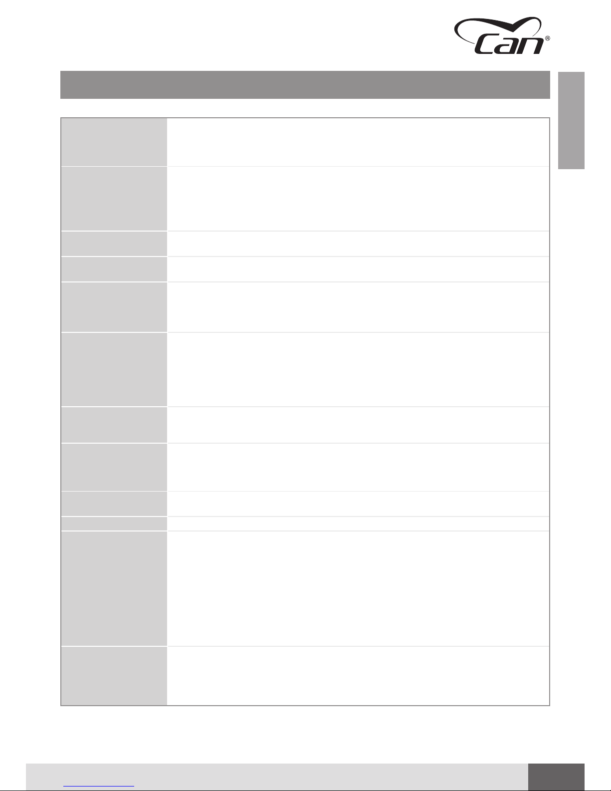
GAS HOB UNITS WITH GLASS RECESSED LID ▪ FC series
TECHNICAL DATA SHEET: FC1348
RECESSED HOLE FC1348
340
460
Please note: secured with adhesive.
19
ENGLISHENGLISH
Installation, use and maintenance instruction manual ▪ Ed. 07/2018 Rev. 00
TECHNICAL DATA SHEET: FC1348
Dimensions Width 510 mm (maximum overall dimension)
Depth 390 mm (maximum overall dimension)
Height 80 mm
Weight 3.8 kg
Hob Unit
(straight valves with
bypass Ø 0.36 mm)
Nominal values:
1 x AUXILIARY burner (AUX):
Pn 1.10 kW – injector ø 0.52 mm – consumption 80.00 g/h
1 x SEMIRAPID burner (SR):
Pn 2.00 kW – injector ø 0.70 mm – consumption 145.50 g/h
Device Class
(EN 30-1-1 4.3)
CLASS 3 – Recessed hob unit
Device Category
(EN 30-1-1 5.1.1.2)
CATEGORY I
Admitted Gases
family
(EN 437)
(EN 30-1-1 4.2.2.4)
GAS OF THE THIRD FAMILY
▪ I3 B/P
▪ I3+
Gas Supply CATEGORY I3 B/P
▪ Butane (G30) 30 mbar
▪ Propane (G31) 30 mbar
CATEGORY I3+
▪ Butane (G30) 28-30 mbar
▪ Propane (G31) 37 mbar
Electric Connection
(only for “E” version with
electronic lighting)
ELECTRIC CONNECTION IN EXTRA-LOW VOLTAGE - 12V / DC
Lighting ▪ S (MANUAL) – using external igniter
▪ E (ELECTRONIC) - 12 V/DC GENERATOR - SPARK - 10Kv @ 30 pF
▪ P (PIEZOELECTRIC) – Mechanically/manually operated piezoelectric igniter inserted
in hob unit
Gas Connection
Galvanised steel train: Ø 8 mm - 1 mm thick
smooth end piece (30 mm) suitable for press fitting connecting with rigid / flexible hose
Gas Capillaries Copper capillary pipes: Ø 4 mm – 0.5 mm thick
Materials ▪ Stainless steel AISI 304
▪ Glass
▪ Chromium-plated iron
▪ Zama
▪ Brass
▪ Copper
▪ Galvanised steel
▪ Aluminium alloy
▪ Enamelled steel
▪ Epdm
Declaration of
Conformity
(GAR 2016/426/EC)
▪ no asbestos
▪ suitable materials according to chapters 2 and 3 (Annex I)
▪ there are no welds with melting point lower than 450°C
▪ flammable materials were not used
▪ the materials are suitable according to the requirements of chapter 3.7
 Loading...