

CAN FC Series, FC1336, FC1345, FC1347, FC1348 Installation, Use And Maintenance Instruction Manual
...Page 1
CAN S.r.l.
Via Nazionale 65,
25080 - Puegnago del Garda (BS) ITALY
T. +39 0365 555909
F. +39 0365 651822
info@cansrl.com
www.cansrl.com
DE
HANDBUCH FÜR INSTALLATION,
GEBRAUCH UND WARTUNG
serie FC
IT
MANUALE DI ISTRUZIONI
INSTALLAZIONE-USO-MANUTENZIONE
EN
INSTALLATION, USE AND
MAINTENANCE INSTRUCTION MANUAL
FR
MANUEL D’INSTRUCTIONS D’INSTALLATIOND’UTILISATION-ET D’ENTRETIEN
ES
MANUAL DE INSTRUCCIONES
INSTALACIÓN-USO-MANTENIMIENTO
Page 2
2
ENGLISHENGLISH
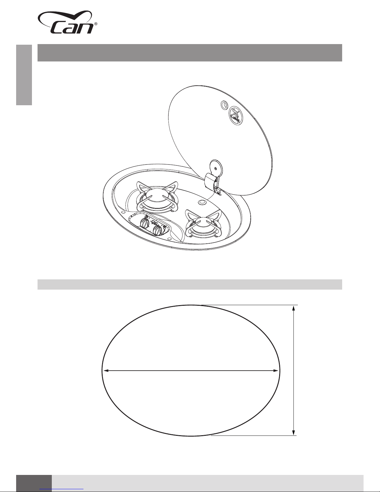
GAS HOB UNITS WITH GLASS RECESSED LID ▪ FC series
Thank you for having purchased our cooking device CAN S.r.l.
This is a quality appliance, made in Italy, that reliably and safely accompanies you throughout your vacation
and leisure time, always guaranteeing high level performance.
Installation and use of the device are simple and straightforward.
Please read this manual carefully: this will allow you to install and use your appliance correctly, always
keeping it in perfect working order for years. The instructions in this booklet only apply to the Country
of destination. The gas supply systems must meet current national standards.
The following symbols have been used in the manual to make it easier to read:
SAFETY-RELATED WARNINGS FOR INSTALLERS AND USERS
Failure to comply with these warnings can cause material damage and jeopardise operation of
the appliance.
GENERAL INFORMATION
Additional information for installers and users.
CAN S.r.l., as the manufacturer of the appliance, reserves the right to make changes to its products and to
this manual considered appropriate, without being obliged to give prior notice. The drawings, installation
diagrams and tables in the manual must be considered as guides and exclusively for explanatory purposes.
CAN S.r.l. prohibits fully or partially copying or reproducing the contents of this manual or forwarding it to
third parties without the consent of the Manufacturer.
revision index
Edition 07/2018
Revision 00
Page 3
3
ENGLISH
DECLARATION OF CONFORMITY
CAN S.r.l.
Italian company with headquarters at:
Via Nazionale, 65 – 25080, Puegnago del Garda ( BS) – ITALY
VAT NO. 03607980988 – REA BS548442
DECLARES THAT
the products called
GAS HOB UNITS WITH GLASS RECESSED LID
FC SERIES – TYPE: FC133X – FC134X – FC135X
Meet all the essential requirements of the GAD Directive – 2009/142/EEC of 30/11/2009 and also the
subsequent GAR regulation - 2016/426/EU of 09/03/2016, as well as the following regulations:
• EC regulation 1935/2004
• EU Regulation no.65/2014 – “ENERGY LABEL”
• EU Regulation no.66/2014 – “ECODESIGN”
Our devices are also manufactured in compliance with all relevant harmonised technical standards for the
sector, in particular:
• EN 30-1-1: 2008 + A3 02/2013
• EN 30-2-1: 2015
We hereby declare that all the products of the FC SERIES are built according to the specifications of the
appliances described in:
TYPE TEST CERTIFICATE no. 51CO4387 issued by IMQ S.p.a.
as notified body, with identification number 0051
The undersigned, Lorenzo Bellini, as director of the company CAN S.r.l., assumes full responsibility for the
truthfulness of the declarations herein.
Puegnago del Garda, 26/03/2018
Signature: Lorenzo Bellini
Page 4
4
ENGLISH
TABLE OF CONTENTS
TECHNICAL DATA SHEET: FC1336 6
TECHNICAL DATA SHEET: FC1337 8
TECHNICAL DATA SHEET: FC1343 10
TECHNICAL DATA SHEET: FC1344 12
TECHNICAL DATA SHEET: FC1345 14
TECHNICAL DATA SHEET: FC1347 16
TECHNICAL DATA SHEET: FC1348 18
TECHNICAL DATA SHEET: FC1349 20
TECHNICAL DATA SHEET: FC1350 22
TECHNICAL DATA SHEET: FC1352 24
GENERAL SAFETY WARNINGS 26
INTENDED USE 27
OBLIGATIONS AND PROHIBITIONS 27
OBLIGATIONS 27
PROHIBITIONS 27
IDENTIFICATION OF THE APPLIANCE 28
RECEIVING THE APPLIANCE 29
CONTROL AND HANDLING 29
DISPOSING OF THE PACKAGING 29
GENERAL PRELIMINARY INFORMATION 26
Page 5
5
ENGLISHENGLISH
Installation, use and maintenance instruction manual ▪ Ed. 07/2018 Rev. 00
INSTRUCTIONS FOR THE INSTALLER 30
INSTALLATION ROOM 30
FEATURES OF INSTALLATION ROOM 30
FLUE GAS EXHAUST 30
INSTALLATION ON SUPPORT STRUCTURE 31
RECESSED HOLE 31
SAFETY DISTANCES 32
POSITIONING THE APPLIANCE 33
GAS CONNECTION 34
GAS CATEGORIES 34
CONNECTION PIPE REQUIREMENTS 34
GAS CONNECTION PROCEDURE 35
ELECTRICAL CONNECTION (ONLY FOR E VERSION) 35
TROUBLESHOOTING AFTER INSTALLATION 36
INSTRUCTIONS FOR USE 37
SPARE PARTS 54
DESCRIPTION 37
SAFETY WARNINGS DURING USE 48
USE 48
LIGHTING THE BURNERS 49
ADJUSTING THE FLAME 50
COOKING OR WARMING UP FOOD 50
SWITCHING OFF THE BURNER 51
OPERATING FAULTS 51
WHAT TO DO IN CASE OF MALFUNCTIONING 51
MAINTENANCE AND CLEANING 52
LONG IDLE PERIODS 53
WASTE DISPOSAL 53
WARRANTY 53
SPARE PARTS - FC1336 54
SPARE PARTS - FC1337 55
SPARE PARTS - FC1343 56
SPARE PARTS - FC1344 56
SPARE PARTS - FC1345 57
SPARE PARTS - FC1347 58
SPARE PARTS - FC1348 59
SPARE PARTS - FC1349 59
SPARE PARTS - FC1350 60
SPARE PARTS - FC1352 61
Page 6
6
ENGLISHENGLISH
GAS HOB UNITS WITH GLASS RECESSED LID ▪ FC series
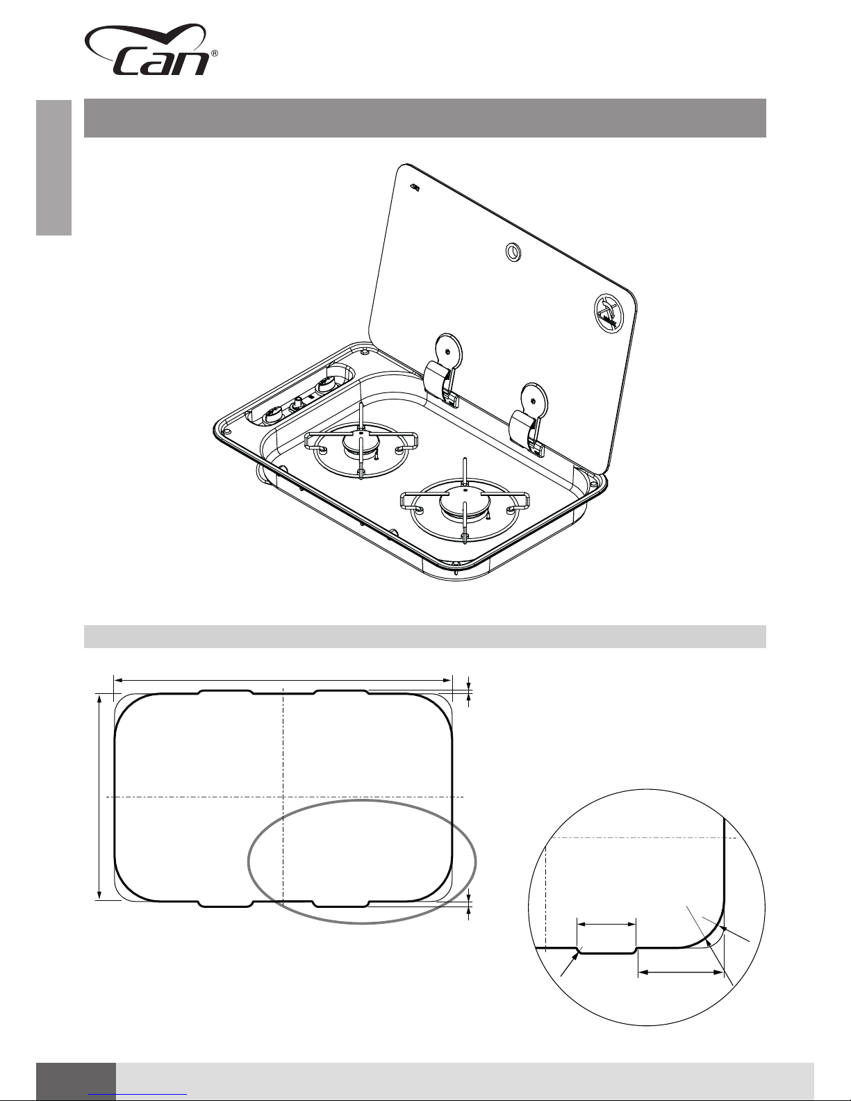
TECHNICAL DATA SHEET: FC1336
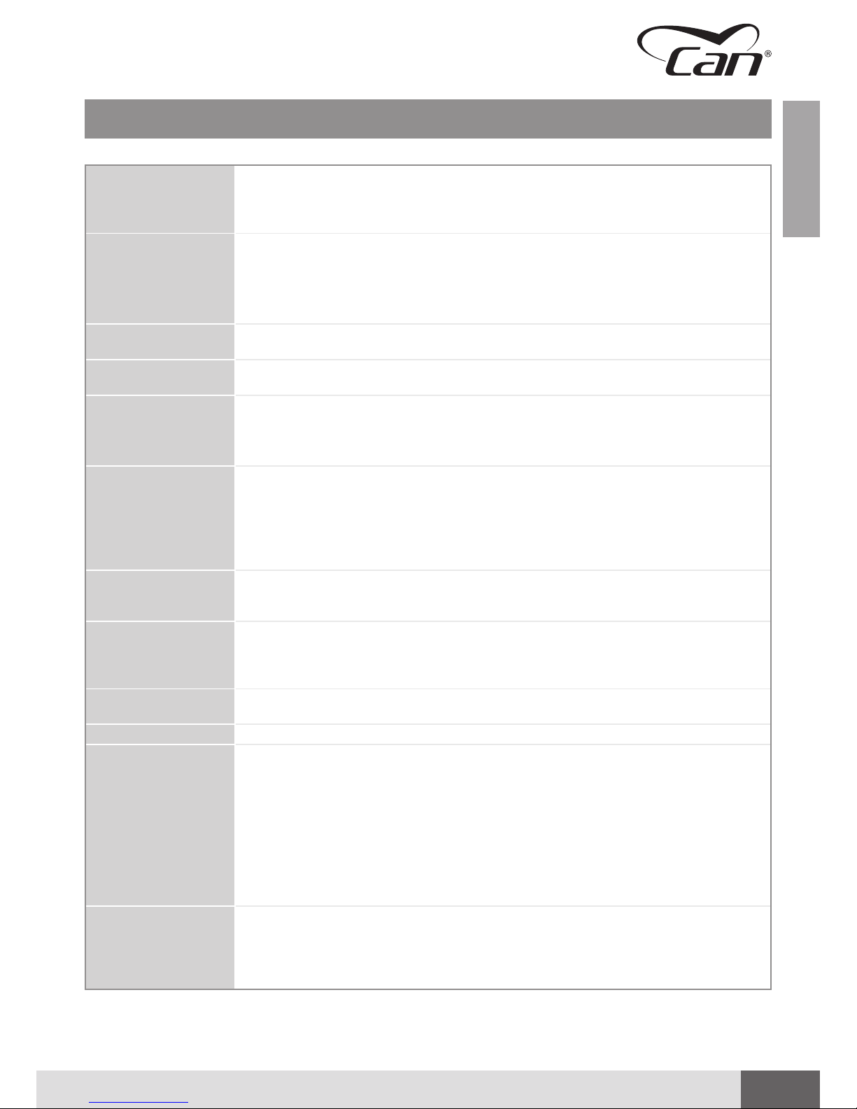
RECESSED HOLE FC1336
C
A
B
5 mm
8 mm
Detail C
85 mm
R10
128 mm
R32
R70
Page 7
7
ENGLISHENGLISH
Installation, use and maintenance instruction manual ▪ Ed. 07/2018 Rev. 00
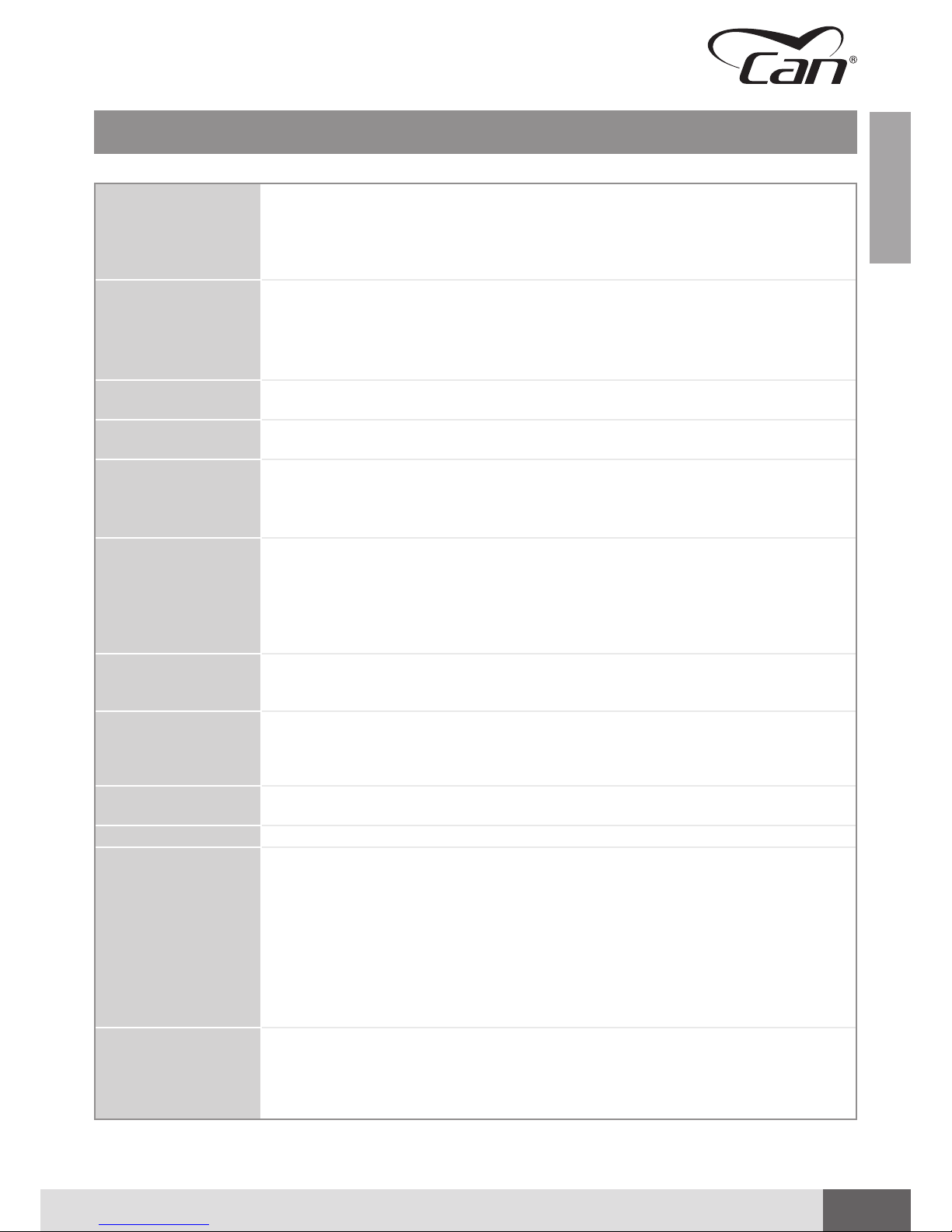
Dimensions Width 530 mm
Depth 340 mm
Height 48 mm (hob area)
105 mm (valves area)
Weight 3.6 kg
Hob Unit
(straight valves with
bypass Ø 0.36 mm)
Nominal values:
1 x AUXILIARY burner (AUX)
Pn 1.00 kW – injector ø 0.50 mm – consumption 72.50 g/h
1 x SEMIRAPID burner (SR):
Pn 1.75 kW – injector ø 0.65 mm – consumption 127.0 g/h
Device Class
(EN 30-1-1 4.3)
CLASS 3 – Recessed hob unit
Device Category
(EN 30-1-1 5.1.1.2)
CATEGORY I
Admitted Gases
family
(EN 437)
(EN 30-1-1 4.2.2.4)
GAS OF THE THIRD FAMILY
▪ I3 B/P
▪ I3+
Gas Supply CATEGORY I3 B/P
▪ Butane (G30) 30 mbar
▪ Propane (G31) 30 mbar
CATEGORY I3+
▪ Butane (G30) 28-30 mbar
▪ Propane (G31) 37 mbar
Electric Connection
(only for “E” version with
electronic lighting)
ELECTRIC CONNECTION IN EXTRA-LOW VOLTAGE - 12V / DC
Lighting ▪ S (MANUAL) – using external igniter
▪ E (ELECTRONIC) - 12 V/DC GENERATOR - SPARK - 10Kv @ 30 pF
▪ P (PIEZOELECTRIC) – Mechanically/manually operated piezoelectric igniter inserted
in hob unit
Gas Connection
Galvanised steel train: Ø 8 mm - 1 mm thick
smooth end piece (30 mm) suitable for press fitting connecting with rigid / flexible hose
Gas Capillaries Copper capillary pipes: Ø 4 mm – 0.5 mm thick
Materials ▪ Stainless steel AISI 304
▪ Glass
▪ Chromium-plated iron
▪ Zama
▪ Brass
▪ Copper
▪ Galvanised steel
▪ Aluminium alloy
▪ Enamelled steel
▪ Epdm
Declaration of
Conformity
(GAR 2016/426/EC)
▪ no asbestos
▪ suitable materials according to chapters 2 and 3 (Annex I)
▪ there are no welds with melting point lower than 450°C
▪ flammable materials were not used
▪ the materials are suitable according to the requirements of chapter 3.7
TECHNICAL DATA SHEET: FC1336
Page 8
8
ENGLISHENGLISH
GAS HOB UNITS WITH GLASS RECESSED LID ▪ FC series
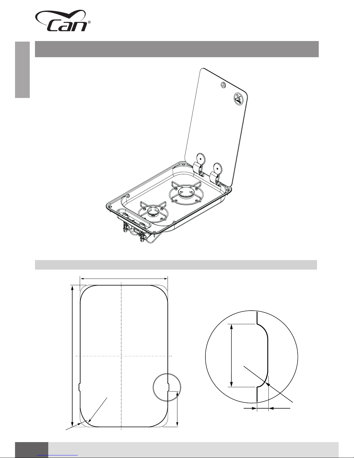
TECHNICAL DATA SHEET: FC1337
RECESSED HOLE FC1337
C
Detail C
A
B
R32
R70
130 mm
30 mm
R8
5
Page 9

9
ENGLISHENGLISH
Installation, use and maintenance instruction manual ▪ Ed. 07/2018 Rev. 00
TECHNICAL DATA SHEET: FC1337
Dimensions Width 340 mm
Depth 530 mm
Height 48 mm (hob area)
105 mm (valves area)
Weight 3.8 kg
Hob Unit
(straight valves with
bypass Ø 0.36 mm)
Nominal values:
1 x AUXILIARY burner (AUX)
Pn 1.00 kW – injector ø 0.50 mm – consumption 72.50 g/h
1 x SEMIRAPID burner (SR):
Pn 1.75 kW – injector ø 0.65 mm – consumption 127.0 g/h
Device Class
(EN 30-1-1 4.3)
CLASS 3 – Recessed hob unit
Device Category
(EN 30-1-1 5.1.1.2)
CATEGORY I
Admitted Gases
family
(EN 437)
(EN 30-1-1 4.2.2.4)
GAS OF THE THIRD FAMILY
▪ I3 B/P
▪ I3+
Gas Supply CATEGORY I3 B/P
▪ Butane (G30) 30 mbar
▪ Propane (G31) 30 mbar
CATEGORY I3+
▪ Butane (G30) 28-30 mbar
▪ Propane (G31) 37 mbar
Electric Connection
(only for “E” version with
electronic lighting)
ELECTRIC CONNECTION IN EXTRA-LOW VOLTAGE - 12V / DC
Lighting ▪ S (MANUAL) – using external igniter
▪ E (ELECTRONIC) - 12 V/DC GENERATOR - SPARK - 10Kv @ 30 pF
▪ P (PIEZOELECTRIC) – Mechanically/manually operated piezoelectric igniter inserted
in hob unit
Gas Connection
Galvanised steel train: Ø 8 mm - 1 mm thick
smooth end piece (30 mm) suitable for press fitting connecting with rigid / flexible hose
Gas Capillaries Copper capillary pipes: Ø 4 mm – 0.5 mm thick
Materials ▪ Stainless steel AISI 304
▪ Glass
▪ Chromium-plated iron
▪ Zama
▪ Brass
▪ Copper
▪ Galvanised steel
▪ Aluminium alloy
▪ Enamelled steel
▪ Epdm
Declaration of
Conformity
(GAR 2016/426/EC)
▪ no asbestos
▪ suitable materials according to chapters 2 and 3 (Annex I)
▪ there are no welds with melting point lower than 450°C
▪ flammable materials were not used
▪ the materials are suitable according to the requirements of chapter 3.7
Page 10

10
ENGLISHENGLISH
GAS HOB UNITS WITH GLASS RECESSED LID ▪ FC series
TECHNICAL DATA SHEET: FC1343
A
B
R32
R80
R340
RECESSED HOLE FC1343
Page 11

11
ENGLISHENGLISH
Installation, use and maintenance instruction manual ▪ Ed. 07/2018 Rev. 00
TECHNICAL DATA SHEET: FC1343
Dimensions Width 480 mm
Depth 480 mm
Height 105 mm
Weight 5.5 kg
Hob Unit
(straight valves with
bypass Ø 0.36 mm)
Nominal values:
1 x AUXILIARY burner (AUX)
Pn 1.00 kW – injector ø 0.50 mm – consumption 72.50 g/h
2 x SEMIRAPID burner (SR):
Pn 1.75 kW – injector ø 0.65 mm – consumption 127.0 g/h
Device Class
(EN 30-1-1 4.3)
CLASS 3 – Recessed hob unit
Device Category
(EN 30-1-1 5.1.1.2)
CATEGORY I
Admitted Gases
family
(EN 437)
(EN 30-1-1 4.2.2.4)
GAS OF THE THIRD FAMILY
▪ I3 B/P
▪ I3+
Gas Supply CATEGORY I3 B/P
▪ Butane (G30) 30 mbar
▪ Propane (G31) 30 mbar
CATEGORY I3+
▪ Butane (G30) 28-30 mbar
▪ Propane (G31) 37 mbar
Electric Connection
(only for “E” version with
electronic lighting)
ELECTRIC CONNECTION IN EXTRA-LOW VOLTAGE - 12V / DC
Lighting ▪ S (MANUAL) – using external igniter
▪ E (ELECTRONIC) - 12 V/DC GENERATOR - SPARK - 10Kv @ 30 pF
Gas Connection
Galvanised steel train: Ø 8 mm - 1 mm thick
smooth end piece (30 mm) suitable for press fitting connecting with rigid / flexible hose
Gas Capillaries Copper capillary pipes: Ø 4 mm – 0.5 mm thick
Materials ▪ Stainless steel AISI 304
▪ Glass
▪ Chromium-plated iron
▪ Zama
▪ Brass
▪ Copper
▪ Galvanised steel
▪ Aluminium alloy
▪ Enamelled steel
▪ Epdm
Declaration of
Conformity
(GAR 2016/426/EC)
▪ no asbestos
▪ suitable materials according to chapters 2 and 3 (Annex I)
▪ there are no welds with melting point lower than 450°C
▪ flammable materials were not used
▪ the materials are suitable according to the requirements of chapter 3.7
Page 12
12
ENGLISHENGLISH
GAS HOB UNITS WITH GLASS RECESSED LID ▪ FC series
TECHNICAL DATA SHEET: FC1344
RECESSED HOLE FC1344
A
B
R32
R80
R340
Page 13

13
ENGLISHENGLISH
Installation, use and maintenance instruction manual ▪ Ed. 07/2018 Rev. 00
TECHNICAL DATA SHEET: FC1344
Dimensions Width 480 mm
Depth 480 mm
Height 105 mm
Weight 5.5 kg
Hob Unit
(straight valves with
bypass Ø 0.36 mm)
Nominal values:
1 x AUXILIARY burner (AUX)
Pn 1.00 kW – injector ø 0.50 mm – consumption 72.50 g/h
2 x SEMIRAPID burner (SR):
Pn 1.75 kW – injector ø 0.65 mm – consumption 127.0 g/h
Device Class
(EN 30-1-1 4.3)
CLASS 3 – Recessed hob unit
Device Category
(EN 30-1-1 5.1.1.2)
CATEGORY I
Admitted Gases
family
(EN 437)
(EN 30-1-1 4.2.2.4)
GAS OF THE THIRD FAMILY
▪ I3 B/P
▪ I3+
Gas Supply CATEGORY I3 B/P
▪ Butane (G30) 30 mbar
▪ Propane (G31) 30 mbar
CATEGORY I3+
▪ Butane (G30) 28-30 mbar
▪ Propane (G31) 37 mbar
Electric Connection
(only for “E” version with
electronic lighting)
ELECTRIC CONNECTION IN EXTRA-LOW VOLTAGE - 12V / DC
Lighting ▪ S (MANUAL) – using external igniter
▪ E (ELECTRONIC) - 12 V/DC GENERATOR - SPARK - 10Kv @ 30 pF
Gas Connection
Galvanised steel train: Ø 8 mm - 1 mm thick
smooth end piece (30 mm) suitable for press fitting connecting with rigid / flexible hose
Gas Capillaries Copper capillary pipes: Ø 4 mm – 0.5 mm thick
Materials ▪ Stainless steel AISI 304
▪ Glass
▪ Chromium-plated iron
▪ Zama
▪ Brass
▪ Copper
▪ Galvanised steel
▪ Aluminium alloy
▪ Enamelled steel
▪ Epdm
Declaration of
Conformity
(GAR 2016/426/EC)
▪ no asbestos
▪ suitable materials according to chapters 2 and 3 (Annex I)
▪ there are no welds with melting point lower than 450°C
▪ flammable materials were not used
▪ the materials are suitable according to the requirements of chapter 3.7
Page 14
14
ENGLISHENGLISH
GAS HOB UNITS WITH GLASS RECESSED LID ▪ FC series
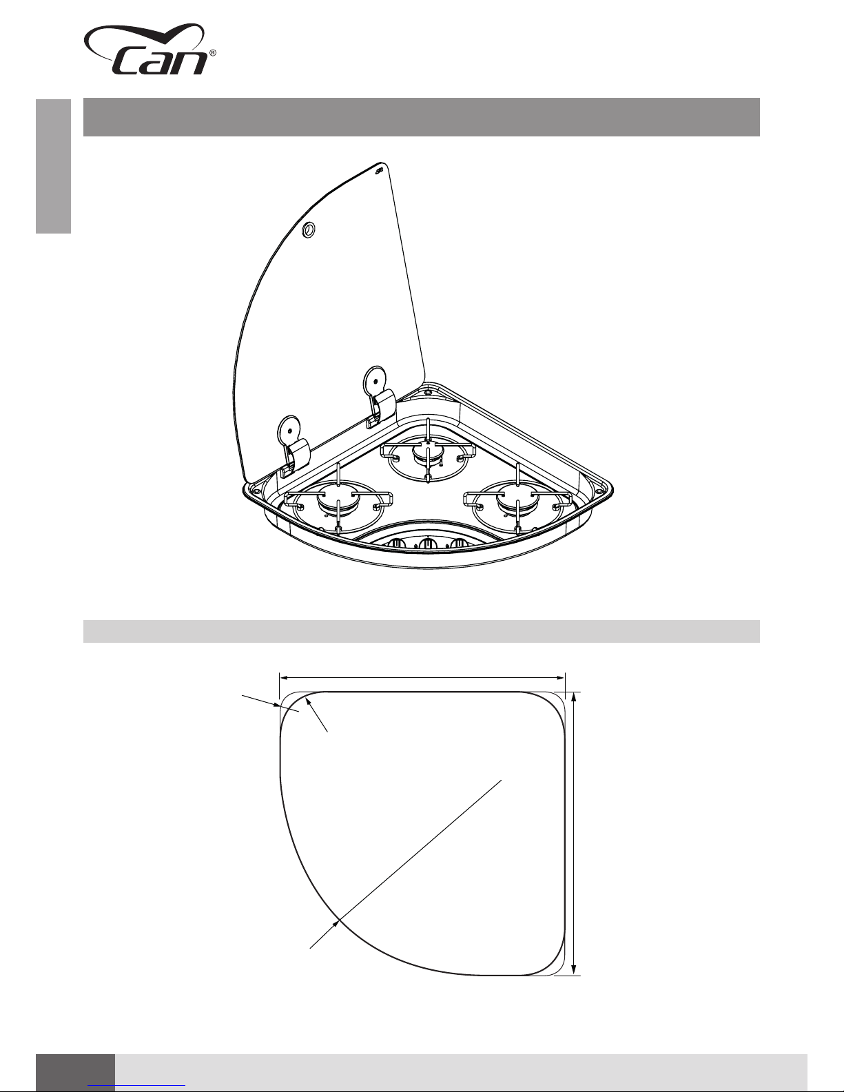
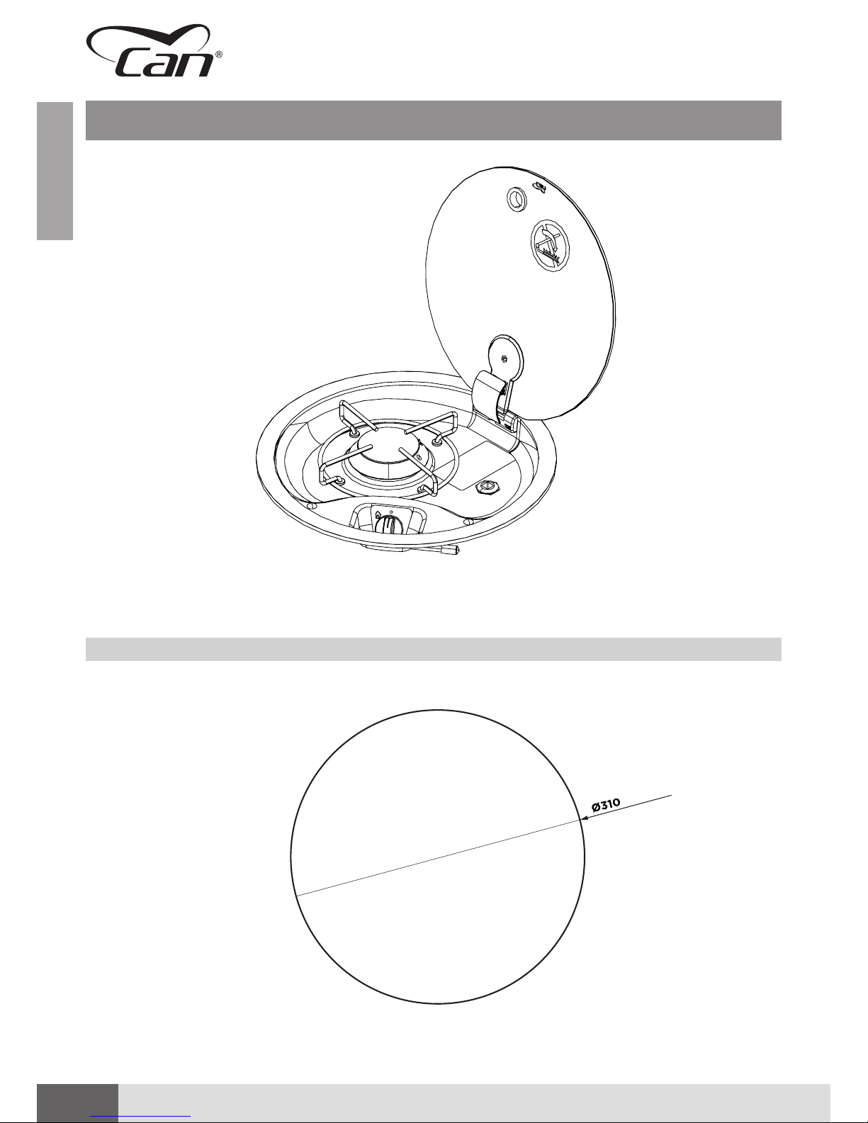
TECHNICAL DATA SHEET: FC1345
RECESSED HOLE FC1345
Please note: secured with adhesive.
Page 15
15
ENGLISHENGLISH
Installation, use and maintenance instruction manual ▪ Ed. 07/2018 Rev. 00
TECHNICAL DATA SHEET: FC1345
Dimensions External Diameter (Ø) 340 mm
Height 80 mm
Weight 2.1 kg
Hob Unit
(straight valves with
bypass Ø 0.36 mm)
Nominal values:
1 x SEMIRAPID burner (SR):
Pn 2.00 kW – injector ø 0.70 mm – consumption 145.50 g/h
Device Class
(EN 30-1-1 4.3)
CLASS 3 – Recessed hob unit
Device Category
(EN 30-1-1 5.1.1.2)
CATEGORY I
Admitted Gases
family
(EN 437)
(EN 30-1-1 4.2.2.4)
GAS OF THE THIRD FAMILY
▪ I3 B/P
▪ I3+
Gas Supply CATEGORY I3 B/P
▪ Butane (G30) 30 mbar
▪ Propane (G31) 30 mbar
CATEGORY I3+
▪ Butane (G30) 28-30 mbar
▪ Propane (G31) 37 mbar
Electric Connection
(only for “E” version with
electronic lighting)
ELECTRIC CONNECTION IN EXTRA-LOW VOLTAGE - 12V / DC
Lighting ▪ S (MANUAL) – using external igniter
▪ E (ELECTRONIC) - 12 V/DC GENERATOR - SPARK - 10Kv @ 30 pF
Gas Connection Galvanised steel train: Ø 8 mm - 1 mm thick
smooth end piece (30 mm) suitable for press fitting connecting with rigid / flexible hose
Gas Capillaries Copper capillary pipes: Ø 4 mm – 0.5 mm thick
Materials ▪ Stainless steel AISI 304
▪ Glass
▪ Chromium-plated iron
▪ Zama
▪ Brass
▪ Copper
▪ Galvanised steel
▪ Aluminium alloy
▪ Enamelled steel
▪ Epdm
Declaration of
Conformity
(GAR 2016/426/EC)
▪ no asbestos
▪ suitable materials according to chapters 2 and 3 (Annex I)
▪ there are no welds with melting point lower than 450°C
▪ flammable materials were not used
▪ the materials are suitable according to the requirements of chapter 3.7
Page 16

16
ENGLISHENGLISH
GAS HOB UNITS WITH GLASS RECESSED LID ▪ FC series
TECHNICAL DATA SHEET: FC1347
RECESSED HOLE FC1347
A
B
R60
R100
Page 17
17
ENGLISHENGLISH
Installation, use and maintenance instruction manual ▪ Ed. 07/2018 Rev. 00
TECHNICAL DATA SHEET: FC1347
Dimensions Width 440 mm
Depth 440 mm
Height 80 mm
Weight 5.3 kg
Hob Unit
(straight valves with
bypass Ø 0.36 mm)
Nominal values:
1 x AUXILIARY burner (AUX):
Pn 1.10 kW – injector ø 0.52 mm – consumption 80.00 g/h
2 x SEMIRAPID burner (SR):
Pn 2.00 kW – injector ø 0.70 mm – consumption 145.50 g/h
Device Class
(EN 30-1-1 4.3)
CLASS 3 – Recessed hob unit
Device Category
(EN 30-1-1 5.1.1.2)
CATEGORY I
Admitted Gases
family
(EN 437)
(EN 30-1-1 4.2.2.4)
GAS OF THE THIRD FAMILY
▪ I3 B/P
▪ I3+
Gas Supply CATEGORY I3 B/P
▪ Butane (G30) 30 mbar
▪ Propane (G31) 30 mbar
CATEGORY I3+
▪ Butane (G30) 28-30 mbar
▪ Propane (G31) 37 mbar
Electric Connection
(only for “E” version with
electronic lighting)
ELECTRIC CONNECTION IN EXTRA-LOW VOLTAGE - 12V / DC
Lighting ▪ S (MANUAL) – using external igniter
▪ E (ELECTRONIC) - 12 V/DC GENERATOR - SPARK - 10Kv @ 30 pF
Gas Connection
Galvanised steel train: Ø 8 mm - 1 mm thick
smooth end piece (30 mm) suitable for press fitting connecting with rigid / flexible hose
Gas Capillaries Copper capillary pipes: Ø 4 mm – 0.5 mm thick
Materials ▪ Stainless steel AISI 304
▪ Glass
▪ Chromium-plated iron
▪ Zama
▪ Brass
▪ Copper
▪ Galvanised steel
▪ Aluminium alloy
▪ Enamelled steel
▪ Epdm
Declaration of
Conformity
(GAR 2016/426/EC)
▪ no asbestos
▪ suitable materials according to chapters 2 and 3 (Annex I)
▪ there are no welds with melting point lower than 450°C
▪ flammable materials were not used
▪ the materials are suitable according to the requirements of chapter 3.7
Page 18
18
ENGLISHENGLISH
GAS HOB UNITS WITH GLASS RECESSED LID ▪ FC series
TECHNICAL DATA SHEET: FC1348
RECESSED HOLE FC1348
340
460
Please note: secured with adhesive.
Page 19
19
ENGLISHENGLISH
Installation, use and maintenance instruction manual ▪ Ed. 07/2018 Rev. 00
TECHNICAL DATA SHEET: FC1348
Dimensions Width 510 mm (maximum overall dimension)
Depth 390 mm (maximum overall dimension)
Height 80 mm
Weight 3.8 kg
Hob Unit
(straight valves with
bypass Ø 0.36 mm)
Nominal values:
1 x AUXILIARY burner (AUX):
Pn 1.10 kW – injector ø 0.52 mm – consumption 80.00 g/h
1 x SEMIRAPID burner (SR):
Pn 2.00 kW – injector ø 0.70 mm – consumption 145.50 g/h
Device Class
(EN 30-1-1 4.3)
CLASS 3 – Recessed hob unit
Device Category
(EN 30-1-1 5.1.1.2)
CATEGORY I
Admitted Gases
family
(EN 437)
(EN 30-1-1 4.2.2.4)
GAS OF THE THIRD FAMILY
▪ I3 B/P
▪ I3+
Gas Supply CATEGORY I3 B/P
▪ Butane (G30) 30 mbar
▪ Propane (G31) 30 mbar
CATEGORY I3+
▪ Butane (G30) 28-30 mbar
▪ Propane (G31) 37 mbar
Electric Connection
(only for “E” version with
electronic lighting)
ELECTRIC CONNECTION IN EXTRA-LOW VOLTAGE - 12V / DC
Lighting ▪ S (MANUAL) – using external igniter
▪ E (ELECTRONIC) - 12 V/DC GENERATOR - SPARK - 10Kv @ 30 pF
▪ P (PIEZOELECTRIC) – Mechanically/manually operated piezoelectric igniter inserted
in hob unit
Gas Connection
Galvanised steel train: Ø 8 mm - 1 mm thick
smooth end piece (30 mm) suitable for press fitting connecting with rigid / flexible hose
Gas Capillaries Copper capillary pipes: Ø 4 mm – 0.5 mm thick
Materials ▪ Stainless steel AISI 304
▪ Glass
▪ Chromium-plated iron
▪ Zama
▪ Brass
▪ Copper
▪ Galvanised steel
▪ Aluminium alloy
▪ Enamelled steel
▪ Epdm
Declaration of
Conformity
(GAR 2016/426/EC)
▪ no asbestos
▪ suitable materials according to chapters 2 and 3 (Annex I)
▪ there are no welds with melting point lower than 450°C
▪ flammable materials were not used
▪ the materials are suitable according to the requirements of chapter 3.7
Page 20

20
ENGLISHENGLISH
GAS HOB UNITS WITH GLASS RECESSED LID ▪ FC series
TECHNICAL DATA SHEET: FC1349
FC1349
RECESSED HOLE FC1349
A
B
5 mm
8 mm
C
85 mm
R10
135 mm
R32
R70
Detail C
Page 21

21
ENGLISHENGLISH
Installation, use and maintenance instruction manual ▪ Ed. 07/2018 Rev. 00
TECHNICAL DATA SHEET: FC1349
Dimensions Width 716 mm
Depth 340 mm
Height 48 mm (hob area depth)
102 mm (gas circuit depth)
Weight 5.6 kg
Hob Unit
(straight valves with
bypass Ø 0.36 mm)
Nominal values:
1 x AUXILIARY burner (AUX):
Pn 1.10 kW – injector ø 0.50 mm – consumption 72.50 g/h
2 x SEMIRAPID burner (SR):
Pn 1.75 kW – injector ø 0.65 mm – consumption 127.00 g/h
Device Class
(EN 30-1-1 4.3)
CLASS 3 – Recessed hob unit
Device Category
(EN 30-1-1 5.1.1.2)
CATEGORY I
Admitted Gases
family
(EN 437)
(EN 30-1-1 4.2.2.4)
GAS OF THE THIRD FAMILY
▪ I3 B/P
▪ I3+
Gas Supply CATEGORY I3 B/P
▪ Butane (G30) 30 mbar
▪ Propane (G31) 30 mbar
CATEGORY I3+
▪ Butane (G30) 28-30 mbar
▪ Propane (G31) 37 mbar
Electric Connection
(only for “E” version with
electronic lighting)
ELECTRIC CONNECTION IN EXTRA-LOW VOLTAGE - 12V / DC
Lighting ▪ S (MANUAL) – using external igniter
▪ E (ELECTRONIC) - 12 V/DC GENERATOR - SPARK - 10Kv @ 30 pF
Gas Connection
Galvanised steel train: Ø 8 mm - 1 mm thick
smooth end piece (30 mm) suitable for press fitting connecting with rigid / flexible hose
Gas Capillaries Copper capillary pipes: Ø 4 mm – 0.5 mm thick
Materials ▪ Stainless steel AISI 304
▪ Glass
▪ Chromium-plated iron
▪ Zama
▪ Brass
▪ Copper
▪ Galvanised steel
▪ Aluminium alloy
▪ Enamelled steel
▪ Epdm
Declaration of
Conformity
(GAR 2016/426/EC)
▪ no asbestos
▪ suitable materials according to chapters 2 and 3 (Annex I)
▪ there are no welds with melting point lower than 450°C
▪ flammable materials were not used
▪ the materials are suitable according to the requirements of chapter 3.7
Page 22

22
ENGLISHENGLISH
GAS HOB UNITS WITH GLASS RECESSED LID ▪ FC series
TECHNICAL DATA SHEET: FC1350
RECESSED HOLE FC1350
A
B
5 mm
8 mm
C
85 mm
R10
135 mm
R32
R70
Detail C
Page 23

23
ENGLISHENGLISH
Installation, use and maintenance instruction manual ▪ Ed. 07/2018 Rev. 00
TECHNICAL DATA SHEET: FC1350
Dimensions Width 716 mm
Depth 340 mm
Height 48 mm (hob area depth)
102 mm (gas circuit depth)
Weight 5.6 kg
Hob Unit
(straight valves with
bypass Ø 0.36 mm)
Nominal values:
1 x AUXILIARY burner (AUX):
Pn 1.10 kW – injector ø 0.50 mm – consumption 72.50 g/h
2 x SEMIRAPID burner (SR):
Pn 1.75 kW – injector ø 0.65 mm – consumption 127.00 g/h
Device Class
(EN 30-1-1 4.3)
CLASS 3 – Recessed hob unit
Device Category
(EN 30-1-1 5.1.1.2)
CATEGORY I
Admitted Gases
family
(EN 437)
(EN 30-1-1 4.2.2.4)
GAS OF THE THIRD FAMILY
▪ I3 B/P
▪ I3+
Gas Supply CATEGORY I3 B/P
▪ Butane (G30) 30 mbar
▪ Propane (G31) 30 mbar
CATEGORY I3+
▪ Butane (G30) 28-30 mbar
▪ Propane (G31) 37 mbar
Electric Connection
(only for “E” version with
electronic lighting)
ELECTRIC CONNECTION IN EXTRA-LOW VOLTAGE - 12V / DC
Lighting ▪ S (MANUAL) – using external igniter
▪ E (ELECTRONIC) - 12 V/DC GENERATOR - SPARK - 10Kv @ 30 pF
Gas Connection
Galvanised steel train: Ø 8 mm - 1 mm thick
smooth end piece (30 mm) suitable for press fitting connecting with rigid / flexible hose
Gas Capillaries Copper capillary pipes: Ø 4 mm – 0.5 mm thick
Materials ▪ Stainless steel AISI 304
▪ Glass
▪ Chromium-plated iron
▪ Zama
▪ Brass
▪ Copper
▪ Galvanised steel
▪ Aluminium alloy
▪ Enamelled steel
▪ Epdm
Declaration of
Conformity
(GAR 2016/426/EC)
▪ no asbestos
▪ suitable materials according to chapters 2 and 3 (Annex I)
▪ there are no welds with melting point lower than 450°C
▪ flammable materials were not used
▪ the materials are suitable according to the requirements of chapter 3.7
Page 24

24
ENGLISHENGLISH
GAS HOB UNITS WITH GLASS RECESSED LID ▪ FC series
A
B
304 mm
Ø 10
350 mm 350 mm
TECHNICAL DATA SHEET: FC1352
RECESSED HOLE FC1352
D
Detail D
C
85 mm
5
R10
8
R10
40
8
R10
40
Detail C
Page 25

25
ENGLISHENGLISH
Installation, use and maintenance instruction manual ▪ Ed. 07/2018 Rev. 00
TECHNICAL DATA SHEET: FC1352
Dimensions Width 748 mm
Depth 310 mm
Height 54 mm (hob area depth)
110 mm (gas circuit depth)
Weight 5.8 kg
Hob Unit
(straight valves with
bypass Ø 0.36 mm)
Nominal values:
1 x AUXILIARY burner (AUX):
Pn 1.10 kW – injector ø 0.52 mm – consumption 80.00 g/h
2 x SEMIRAPID burner (SR):
Pn 2.00 kW – injector ø 0.70 mm – consumption 145.50 g/h
Device Class
(EN 30-1-1 4.3)
CLASS 3 – Recessed hob unit
Device Category
(EN 30-1-1 5.1.1.2)
CATEGORY I
Admitted Gases
family
(EN 437)
(EN 30-1-1 4.2.2.4)
GAS OF THE THIRD FAMILY
▪ I3 B/P
▪ I3+
Gas Supply CATEGORY I3 B/P
▪ Butane (G30) 30 mbar
▪ Propane (G31) 30 mbar
CATEGORY I3+
▪ Butane (G30) 28-30 mbar
▪ Propane (G31) 37 mbar
Electric Connection
(only for “E” version with
electronic lighting)
ELECTRIC CONNECTION IN EXTRA-LOW VOLTAGE - 12V / DC
Lighting ▪ S (MANUAL) – using external igniter
▪ E (ELECTRONIC) - 12 V/DC GENERATOR - SPARK - 10Kv @ 30 pF
Gas Connection
Galvanised steel train: Ø 8 mm - 1 mm thick
smooth end piece (30 mm) suitable for press fitting connecting with rigid / flexible hose
Gas Capillaries Copper capillary pipes: Ø 4 mm – 0.5 mm thick
Materials ▪ Stainless steel AISI 304
▪ Glass
▪ Chromium-plated iron
▪ Zama
▪ Brass
▪ Copper
▪ Galvanised steel
▪ Aluminium alloy
▪ Enamelled steel
▪ Epdm
Declaration of
Conformity
(GAR 2016/426/EC)
▪ no asbestos
▪ suitable materials according to chapters 2 and 3 (Annex I)
▪ there are no welds with melting point lower than 450°C
▪ flammable materials were not used
▪ the materials are suitable according to the requirements of chapter 3.7
Page 26

26
ENGLISH
GENERAL PRELIMINARY INFORMATION
Read these instructions carefully before installing and/or using the appliance.
This installation, use and maintenance instruction manual is an integral part of the appliance. Keep this
documentation in a place which all users may have access for future reference. If the appliance is transferred
or sold, make sure that this booklet is also delivered to the new user in order to inform them of the installation
procedure, use and safety requirements.
GENERAL SAFETY WARNINGS
ATTENTION!
CAN S.r.l. will not be held liable for any use other than indicated. Do not use this appliance as
a room heater.
ATTENTION!
Do not modify the appliance, unless the change is authorised and carried out by the
Manufacturer or by his authorised technicians.
ATTENTION!
CAN S.r.l. will not be held liable for personal harm or property damage caused by failure to
comply with the above-mentioned provisions or resulting from tampering with even a single
part of the appliance and using non-original spare parts.
ATTENTION!
Wear the proper personal protective equipment during installation. Also follow the applicable
safety standards.
ATTENTION!
Gas and electric appliances must only be installed by qualified and certified professionals.
ATTENTION!
Make sure that the type of gas and pressure match the specifications of the appliance. The
specifications are shown on the data plate.
ATTENTION!
Pay the utmost attention to standards regarding ventilation of the installation rooms, currently
in force in the country of use.
ATTENTION!
If it is not possible to assemble the device according to the instructions herein, contact
CAN S.r.l.
ATTENTION!
Only replace failed or faulty components with original spare parts CAN S.r.l.
ATTENTION!
Do not close the glass lid when the burners are lit or still hot.
Page 27

27
ENGLISHENGLISH
Installation, use and maintenance instruction manual ▪ Ed. 07/2018 Rev. 00
ATTENTION!
Do not allow the cooking vessels to come into contact with the glass lids, the hinges or other
plastic components while the device is in use.
INTENDED USE
The appliance is intended to cook and warm up food. Any other use must be considered improper.
CAN S.r.l. will not be held liable for any use other than indicated.
▪ Do not use the appliance outdoors.
▪ Do not use this appliance as a room heater.
ATTENTION!
Using a gas fired appliance produces heat and humidity in the room it is installed in. Always
guarantee proper ventilation of the rooms keeping air vents/intakes or windows open. If this
is not enough, install a mechanical ventilation/extraction device for the combustion products
(e.g. extractor hood).
ATTENTION!
The appliance is equipped with a glass lid. Glass lids can shatter if overheated or struck by
blunt objects. Always open the lid before lighting any burner, making sure to switch the
burners off and let them cool for a few minutes before reclosing the glass lid at the end of
each operating cycle.
OBLIGATIONS AND PROHIBITIONS
OBLIGATIONS
▪ The appliance’s installation site must have a regulation ventilation system, according to standards in
the sector, be in good maintenance condition and proper working order, as well as appropriately sized
for the purpose.
▪ Follow the instructions in chapter "Instructions for the installer" when installing the appliance.
Installation must only be carried out by qualified technical personnel.
▪ The appliance must only be used with the types of gas indicated in paragraph "Gas categories".
▪ When operating the appliance, only use suitable pots and pans (refer to the specific paragraph)
on the appropriate pan supports supplied with the hob units. Make sure that these devices remain
perfectly horizontal and parallel to the hob, so that they do not tip over and risk causing burns and
scalding for the users. Burn hazard.
▪ Always monitor the hob unit while in use and especially when cooking very greasy dishes or fried
food.
PROHIBITIONS
▪ Do not install the appliance if damaged upon delivery.
▪ Never leave the appliance unattended while in use.
▪ Do not allow the appliance to be used by children younger than 14 years old or persons with reduced
physical, mental or sensory capabilities or without adequate knowledge.
▪ The cooking areas and nearby surfaces become very hot. Do not touch high temperature surfaces.
Burn hazard.
▪ Do not close the lid of the appliance while in use.
▪ Do not use vessels which are damaged, of an inappropriate size and/or which extend beyond the
edges of the hob unit or are positioned improperly.
Page 28

28
ENGLISHENGLISH
GAS HOB UNITS WITH GLASS RECESSED LID ▪ FC series
▪ Do not heat empty pans or without a sufficient amount of cooking fluid.
▪ Do not expose the appliance to air draughts. The burners could go out.
▪ Do not force the knobs if blocked. Contact the Technical Assistance Service.
▪ Do not use the hob unit as a support surface.
▪ Do not modify or tamper with the appliance in any way.
▪ Do not place heat sensitive or flammable objects (e.g. mitts, curtains, alcoholic beverages, etc.) near
the appliance.
IDENTIFICATION OF THE APPLIANCE
There is an identification label at the bottom of the appliance bearing:
▪ serial number information,
▪ typological/functional features,
▪ certification data and CE marking.
The CE marking certifies that the product meets the requirements of EU regulation 2016/426
on appliances burning gaseous fuels.
ATTENTION!
The identification plate must not be removed.
1
9
3 11
10
8 7
4 25 6
pos.
element
1
Manufacturer Logo
2
Manufacturer Address
3
Name of appliance family
4
Series and type
5
Model
6
EC certification serial number
7
Operating pressures - Type-approval parameters - Countries
8
Total power and consumption
9
Barcode - Production serial number
10
Production data
11
CE marking applied by manufacturer
Page 29

29
ENGLISHENGLISH
Installation, use and maintenance instruction manual ▪ Ed. 07/2018 Rev. 00
RECEIVING THE APPLIANCE
The appliance is delivered to the customer in a cardboard box (A), protected by shaped polystyrene shells
(B) to avoid damage during transport and storage.
In addition to the appliance, the box also contains:
▪ the installation, use and maintenance manual (C),
▪ a fixing kit (D) including screws and accessories for installation of the appliance on the support structure.
A
B
D
C
CAN S.r.l.
Via Nazionale 65,
25080 - Puegnago del Garda (BS) ITALY
T. +39 0365 555909
F. +39 0365 651822
info@cansrl.com
www.cansrl.com
DE
HANDBUCH FÜR INSTALLATION,
GEBRAUCH UND WARTUNG
serie FC
IT
MANUALE DI ISTRUZIONI
INSTALLAZIONE-USO-MANUTENZIONE
EN
INSTALLATION, USE AND
MAINTENANCE INSTRUCTION MANUAL
FR
MANUEL D’INSTRUCTIONS D’INSTALLATIOND’UTILISATION-ET D’ENTRETIEN
ES
MANUAL DE INSTRUCCIONES
INSTALACIÓN-USO-MANTENIMIENTO
CONTROL AND HANDLING
Upon receiving the appliance, proceed to unpack it.
After having removed all the packaging material and protective film, check for any faults.
Should any faults be discovered, do not install the appliance and contact your dealer within 8 days from
the date of purchase, reporting the data on the identification label of the appliance and the problems
encountered.
ATTENTION!
Do not leave unattended or release the packaging or parts of it into the environment because
they are potentially hazardous (risk of suffocation for children and animals).
Lift the appliance by hand to move it to the installation site.
ATTENTION!
During handling, take care not to damage the appliance, persons, animals or objects in the
immediate vicinity.
DISPOSING OF THE PACKAGING
The materials used for packaging are recyclable and must be collected according to local standards on
separate waste collection.
ATTENTION!
Separate the different materials making up the packaging and dispose of them in compliance
with standards in force in the Country of installation.
Page 30

30
ENGLISH
INSTRUCTIONS FOR THE INSTALLER
ATTENTION!
Installation and all the interventions on the appliance described in this instruction manual
must be carried out by qualified technical personnel and in compliance with standards in
force.
ATTENTION!
The gas connection systems and the installation rooms must be suitable and meet the safety
standards in force in the Country of use.
ATTENTION!
During installation, maintenance or repair operations, always close the main gas valves, so
that the gas supply line to the hob unit is "GAS FREE" and there is no risk of fire/explosion or
poisoning/suffocation.
ATTENTION!
Make sure the power line is also disconnected to avoid the risk of the installer being
electrocuted.
▪ Do not install or use the appliance if damaged.
▪ Respect the minimum distance from the walls and other equipment (see paragraph “Safety distances”).
▪ The appliance is not connected to a combustion product extractor device. The user must make sure
that the appliance is installed in an environment with a high ventilation rate.
INSTALLATION ROOM
FEATURES OF INSTALLATION ROOM
The appliance was not designed to work outdoors. It is not allowed to install the appliance
outdoors and directly exposed to the elements.
The appliance must be installed indoors, in a room suitable for the purpose. The room was meet the safety
standards in force in the Country of use.
ATTENTION!
The installation rooms must have a continuous air exchange or at least such to guarantee normal
and correct gas combustion (according to standard UNI 7131 or other technical standards of
reference in the sectors of use, for example EN721 - EN1645-1 - EN1646-1 - EN1949 - EN ISO 10293).
FLUE GAS EXHAUST
The appliance is not equipped with an extraction/exhaust system of flue gas and combustion products.
Always check that there are proper ventilation vents in the room.
If a hood is installed above the hob unit, refer to the installation instructions of the hood which
shows the correct distance to be respected.
Page 31

31
ENGLISHENGLISH
Installation, use and maintenance instruction manual ▪ Ed. 07/2018 Rev. 00
INSTALLATION ON SUPPORT STRUCTURE
The appliance must be mounted on a support structure, made of material resistant to heat and with all of
the sturdiness requirements indicated by the technical sector standards (for example EN14749). The work
table must be perfectly horizontal and perpendicular to all surrounding vertical panelling. The area near
the appliance could get very hot. Pay the utmost attention and do not place sockets, other household
appliances, power cables, piping and any other heat-sensitive or flammable material in this area.
ATTENTION!
The appliance must be installed in a room without air draughts which can have a negative
effect on combustion. The chosen installation position must also prevent the accumulation of
unburnt gases.
Comply with the sizes indicated in this manual. Any deviation could cause the temperature to rise excessively.
The surrounding surfaces must be able to withstand temperature rises admitted by standard EN30-1-1 and in
compliance with the design of this unit. All combustible material, such as curtains and shelves, must be kept
far away from the appliance. Check the admissible temperature of the materials used for the surrounding
surfaces to guarantee their compliance with the requirements of EN30-1-1.
RECESSED HOLE
The support structure must be provided with a suitable recessed hole. For information regarding the
dimensions of the hole of your model, refer to the table below and follow the drawings in the technical data
sheets of each model in the first section of this manual.
recessed hole sizes
model a
[mm]
b
[mm] Ø [mm]
FC1336 530 340 -
FC1337 340 530 -
FC1343 480 480 -
FC1344 480 480 -
FC1345 - - 340
FC1347 440 440 -
FC1348 510 390 -
FC1349 716 340 -
FC1350 716 340 -
FC1352 748 310 -
Refer to the drawings in the TECHNICAL DATA SHEETS for the recessing details of each model.
Page 32

32
ENGLISHENGLISH
GAS HOB UNITS WITH GLASS RECESSED LID ▪ FC series
SAFETY DISTANCES
The appliance must be kept a certain distance away from side and upper walls. Consult the following table:
dimensions and minimum safety distances for installation
model a
[mm]
b
[mm]
c
[mm]
d
[mm]
e
[mm]
FC1336
50 55 640 650 110
FC1337
50 105 550 650 110
FC1343
50 100 680 650 110
FC1344
50 100 680 650 110
FC1345
50 100 540 650 110
FC1347
50 100 640 650 110
FC1348
50 100 710 650 110
FC1349
50 55 826 650 110
FC1350
50 55 826 650 110
FC1352
50 55 858 650 110
max
150 mm
D
D
E
C
B
A
1
D
C
B
E
A
1
D
C
E
B
A
1
If the appliance is recessed above an oven or another
powered home appliance, a separation panel must
also be installed as indicated in point 1.
Remember to prepare adequate holes in the furniture
to pass through the gas, water and electrical power
pipes of the appliance, if any.
Page 33

33
ENGLISHENGLISH
Installation, use and maintenance instruction manual ▪ Ed. 07/2018 Rev. 00
POSITIONING THE APPLIANCE
Proceed as follows to position the appliance on the support structure:
step action
1 Position the gasket (sold separately) on the edges of the metal moulding or sealant paste (if present).
2 Position the appliance on the recessed hole and push it onto the support structure.
3 Secure the appliance by the fixing screws provided in the specific kit and screw them into the holes made at
the four corners of the metal moulding.
Note: make sure that the appliance is positioned properly in the slot before performing the final fixing.
The following are excluded from the aforementioned fixing system:
▪ models FC1345 and FC1348 which, since they do not have fixing holes, require an adhesive
to be placed on the external perimeter of the metal moulding for them to be glued directly
to the work table;
▪ model FC1352, which is fixed from the bottom in line with the bushings on the lower surface
of the perimeter edge of the hob unit.
ATTENTION!
There must be an opening below the hob of at least 50 x 50 mm for the passage of the gas
and electrical connections.
EQUIPMENT REQUIRED
4 x 4 x
2
1
3
Page 34

34
ENGLISHENGLISH
GAS HOB UNITS WITH GLASS RECESSED LID ▪ FC series
GAS CONNECTION
ATTENTION!
Before setting up the connection, make sure that the gas system and the installation rooms are
suitable for the purpose and comply with the standards in force in the Country of installation.
Refer to the specific technical standards regarding conformity of gas systems (LPG) for the
household (UNI CIG 7131 and 7129), nautical ( UNI EN ISO 10239) and recreational vehicles
(UNI EN 1949) sectors.
Before connecting the gas, check that:
▪ the supply line is free from obstructions and has a sufficient flow rate to guarantee correct operation
of the appliance;
▪ there is a suitable pressure regulator/reducer compliant with the gas categories used on the appliance
immediately downstream of the gas cylinder or container feeding the system;
▪ a gas shut-off valve or a valve disconnecting the system is installed on the supply line, downstream
of the regulator and immediately upstream of the appliance being connected, in a place which can
easily be accessed and inspected (Please note: this valve must always be shut during installation and
maintenance on the appliance).
ATTENTION!
Make sure that the type of gas feeding the appliance is among those allowed and listed in the
instruction booklet (see paragraph “Gas categories”).
CAN S.r.l. declines any liability for incorrect connections, not carried out in a workmanlike manner or
performed by non-professionally qualified individuals.
GAS CATEGORIES
The appliance was designed for correct operation only with the types of gas categories and operating
pressures listed below:
gas category and country of
destination
name of gas operating pressure
I3B/P (30)
AT-BE-DE-DK-FI-GB-NL-NO-PT-SE-SI
Butane (G30)
Propane (G31)
30 mbar
30 mbar
I3+ (28-30/37)
BE-CH-ES-FR-GB-IE-IT-PT-SI
Butane (G30)
Propane (G31)
28 - 30 mbar
37 mbar
CONNECTION PIPE REQUIREMENTS
ATTENTION!
The appliance must be connected to the gas pipeline by means of a suitable connection pipe
making use of certified sealed fittings of the most suitable type for the application.
It is possible to use flexible connection hoses. They must:
▪ always be able to be inspected,
▪ be protected against contact with hot parts (e.g. burner cups),
▪ be protected from the movable parts of the recessing (drawers, doors, etc.),
▪ have a length which complies with the technical standards for each sector of reference.
Avoid any type of mechanical stress on the flexible hoses during installation and use (protection against
traction, twisting, crushing, etc.).
ATTENTION!
Perform maintenance and periodically replace the flexible hose within the expiration date
written on the sheath. Do not use expired or damaged flexible hoses by any means.
Page 35

35
ENGLISHENGLISH
Installation, use and maintenance instruction manual ▪ Ed. 07/2018 Rev. 00
GAS CONNECTION PROCEDURE
The appliance is supplied with a gas train with a
smooth end section and free for at least 30 mm, fit
to house suitable press fittings. Proceed as follows
to set up the gas connection:
Please note: the fittings are not supplied with the product.
They are solely supplied and connected by the installer.
EQUIPMENT REQUIRED
step action
1 Connect the Ø 8 mm pipe to the clamp fitting of
the gas distribution network.
ATTENTION!
During the installation and connection
operations, the gas supply pipe of the
appliance must not be subject to twisting,
traction or any other mechanical stress
which could jeopardise tightness and
strength.
After having connected the appliance to the gas mains, check the tightness of the fittings with soap and
wa t er.
ATTENTION!
It is absolutely prohibited to use naked flames to check tightness and to put the device into
service! If the test is satisfactory, light all the burners to make sure that the flame is regular
and stable.
ELECTRICAL CONNECTION (only for E version)
E versions are equipped with a low voltage spark generator (12 V DC) to light the burners, generally installed
on the metal bracket at the bottom of the hob unit. To connect the generator to the local power mains,
proceed as follows:
step action
-
+
12 V DC
1
1 Power cable positive pole
2 Power cable negative pole
3 Connection cable generator
button
4 Glow plugs fast-on housing
5 Glow plugs fast-on
connectors
6 12V DC (+ -) power supply
fast-on connectors
2
3
4
44
55 5 6
1 Connect the free end of the black conductor (-)
to the negative pole of the terminals of the mains
or of a battery.
2 Connect the free end of the black conductor (+)
to the positive pole of the terminals of the mains
or of a battery.
ATTENTION!
Any type of connection of the appliance
to a power mains other than 12V and in
direct current (DC) is strictly prohibited.
Any other connection can pose a severe
danger for the user of the appliance and
cause irreversible damage to the device
itself.
Page 36

36
ENGLISHENGLISH
GAS HOB UNITS WITH GLASS RECESSED LID ▪ FC series
TROUBLESHOOTING AFTER INSTALLATION
If the appliance does not work properly after installation, perform the controls in the table.
problem possible solutions
The gas flow
seems irregular
Check that the gas cock is completely open.
Check that the fuel supply circuit has a suitable flow rate.
Check that the burner spreaders and relative caps are positioned correctly and free
from obstructions.
Check that the nozzles are suitable for the type of gas used.
Check compatibility and correct calibration of the pressure regulator, if applicable.
Check the gas supply pipe (pipe obstructed, bent/crushed, excessively long,
unsuitable, etc.).
If the appliance still does not work properly after all the checks have been made, contact the
authorised local dealer.
Page 37

37
ENGLISH
INSTRUCTIONS FOR USE
DESCRIPTION
See the exploded drawings on the following pages for the position of the components listed in
the table.
pos.
component
1
Wire pan support
2
Ring for glass lid
3
Glass lid
4
Hinge for glass lid
5
Plastic cap
6
Silent block for resting lid
7
Fixing screws cap
8
Hob unit fixing screw
9
CE label
10
Metal moulding
11
SR burner cup with injector nozzle
12
Gas capillary pipe for SR burner
13
Gas cock with safety valve
14
AUX burner cup with injector nozzle
15
Gas capillary pipe for AUX burner
16
Main gas train
17
SR burner spreader
18
SR burner cap
19
AUX burner spreader
20
AUX burner cap
21
Burner caps and spreaders fixing screws
22
Rubber feet/bushings for pan support
23
Knob for gas cock
24
Gas cock fixing nut
25
Control panel sticker
26
Piezoelectric igniter
27
Ignition glow plug
28
Thermocouple
29
Burner stud bolt
30
Thermocouple fixing nut
31
Glow plug fixing clip
32
Hinge and silentblock fixing screw
33
Glass support rubber buffer
34
Bushing for pan retaining system
35
Single-pole lighting button
Page 38

38
ENGLISHENGLISH
GAS HOB UNITS WITH GLASS RECESSED LID ▪ FC series
TYPE FC1336
detail C
29
2
4
9
detail C
16
17
18
21
22
25
3
6
5
10
26
13
12
7
8
Fixing kit
detail B
detail A
detail A
27
31
detail B
30
28
32
32
24
23
20
19
14
1
11
15
Page 39

39
ENGLISHENGLISH
Installation, use and maintenance instruction manual ▪ Ed. 07/2018 Rev. 00
TYPE FC1337
detail B
30
detail C
29
7
8
Fixing kit
detail A
27
31
28
1
23
32
4
9
11
detail A
detail B
detail C
16 14 15
13
12
26
6
32
25
24
23
17
18
21
22
20
19
Page 40

40
ENGLISHENGLISH
GAS HOB UNITS WITH GLASS RECESSED LID ▪ FC series
TYPE FC1343
15
10
11
16
22
24
detail B
28
25
detail C
29
7
8
Fixing kit
30
2
3
4
32
17
18
19
20
21
1
23
6
32
9
14
1312
detail A
27
31
detail A
detail C
detail B
Page 41

41
ENGLISHENGLISH
Installation, use and maintenance instruction manual ▪ Ed. 07/2018 Rev. 00
TYPE FC1344
15
10
11
16
22
detail B
28
25
detail C
29
7
8
Fixing kit
30
2 3
432
17
18
19
20
21
1
23
6
32
9
14
1312
detail A
27
31
24
detail A
detail B
detail C
Page 42

42
ENGLISHENGLISH
GAS HOB UNITS WITH GLASS RECESSED LID ▪ FC series
TYPE FC1345
detail B
28
30
detail A
27
31
33
32
34
11
1613
12
25
23
24
17
18
22
1
2
10
9
detail A
detail B
3
4
32
Page 43

43
ENGLISHENGLISH
Installation, use and maintenance instruction manual ▪ Ed. 07/2018 Rev. 00
TYPE FC1347
detail B
28
7
8
Fixing kit
30
detail A
27
31
2
1
22
17
18
19
20
4 32
109
23
25
11
12
13
detail A
detail B
16
15
14
3
24
Page 44

44
ENGLISHENGLISH
GAS HOB UNITS WITH GLASS RECESSED LID ▪ FC series
TYPE FC1348
detail B
28
30
detail A
27
31
15
33
34
11
1613
12
25
23
24
22
1
2
10
9
detail A
3
4
32
18
17
20
19
detail B
14
Page 45

45
ENGLISHENGLISH
Installation, use and maintenance instruction manual ▪ Ed. 07/2018 Rev. 00
TYPE FC1349
detail B
28
detail C
29
7
8
Fixing kit
30
detail A
27
31
2
17
18
19
20
4 32
10
9
23
25
11
13
detail A
detail B
16
1
3
22
21
6 5
32
detail C
Page 46

46
ENGLISHENGLISH
GAS HOB UNITS WITH GLASS RECESSED LID ▪ FC series
1
2
3
10
11
12
detail C
16
15
17
18
19
20
22
6
32 5
14
detail B
TYPE FC1350
4
32
23
24
25
13
9
detail A
21
detail B
28
detail C
29
7
8
Fixing kit
30
detail A
27
31
Page 47

47
ENGLISHENGLISH
Installation, use and maintenance instruction manual ▪ Ed. 07/2018 Rev. 00
TYPE FC1352
detail B
28
30
detail A
27
31
1
22
19
20
17
18
6
32
4
32
23
24
25
10
11
16
15
detail B
13
9
14
detail A
12
35
3
Page 48

48
ENGLISHENGLISH
GAS HOB UNITS WITH GLASS RECESSED LID ▪ FC series
SAFETY WARNINGS DURING USE
ATTENTION!
During operation and for a few minutes after use, some parts of the appliance reach very high
temperatures. Do not touch these parts without adequate personal protections. Burn hazard!
▪ Always use the supplied pan supports. Do not place pots and pans directly on the burner spreader
or caps.
▪ Do not cook food in direct contact with the flame.
▪ Do not cover the appliance or parts of it with aluminium foil or similar.
▪ Do not heat tin boxes or hermetically closed containers on the appliance as the overpressure generated
by the heat could make them explode and cause serious personal harm.
▪ Make sure that the cooking vessels sit properly on the pan support without rocking. The diameter of
the vessels must be adequate for the chosen burner and must not protrude from the pan support. The
Manufacturer will not be held liable and will not acknowledge the Warranty rights if this requirement
is neglected.
▪ Always monitor the appliance throughout operation.
▪ Switch the burner off after each use.
▪ Do not set or keep flammable liquids or materials or objects which can easily catch fire on the appliance
or in its immediate vicinity.
▪ Do not place hot pans on the controls.
▪ Do not light the burner without pans and/or with empty pans.
ATTENTION!
If cooking grease or hot oil catches fire, do not put out the flames with water, but suffocate
them with a moist rag or similar and immediately notify the fire brigade.
USE
Before using the appliance for the first time, clean it and all of its components as instructed
in the paragraph “Cleaning”.
The first few times the appliance is used, it could release smoke and unpleasant smells.
There is no reason for concern as this is due to the combustion of the grease used to process it in the
factory. We recommend airing out the rooms.
The burners are equipped with safety thermocouple.
The thermocouple is a heat sensitive device: as long as it is heated by the fire of the lit burner, it
allows gas to exit the nozzle; if the fire goes out accidentally (for example when liquid spills from
the pan), in a few seconds the thermocouple cools off and this blocks the release of gas from the
nozzle preventing the room from being saturated with unburnt gas.
use of burners
OFF
MAX
MIN
Page 49

49
ENGLISHENGLISH
Installation, use and maintenance instruction manual ▪ Ed. 07/2018 Rev. 00
LIGHTING THE BURNERS
ATTENTION!
Before use, make sure that the burner spreaders, caps and pan holders are positioned properly.
burner spreader positioning
The matching burner is indicated on each knob.
The burner can be lit:
▪ manually using the external igniter (on S versions),
▪ electronically with 12 V/DC generator (on E versions),
▪ piezoelectrically with mechanically/manually operated piezoelectric igniter (on P versions).
Proceed as follows to light the burner:
step action
1
2
1 press the knob corresponding to the burner you
want to light and turn it anticlockwise (to the
maximum symbol).
2 Simultaneously, activate the electric (or
piezoelectric) lighting device with several fast
repeated pulses.
3 When lit, keep the knob pressed all the way for
another 5 seconds (at maximum) and then release
it, adjusting the desired intensity of the flame.
Please note: this delay in releasing the knob heats
up the safety thermocouple.
If the burner does not remain lit when you release the knob, it means that the thermocouple did not heat
up sufficiently. To solve this problem, repeat the operations described in the table, holding the knob down
longer after the burner is lit.
ATTENTION!
The burner must be lit without any pan or any other object on the hob unit above the burners.
Page 50

50
ENGLISHENGLISH
GAS HOB UNITS WITH GLASS RECESSED LID ▪ FC series
ADJUSTING THE FLAME
Check that the flame is regular and stable.
To adjust the flame, turn the knob to the desired
position (MIN or MAX).
The knob can also be set in the middle, between the
maximum and minimum position. Do not place the
knob between the maximum and “off” position.
ATTENTION!
If the flame is irregular, check that the
burner spreader and caps are positioned
properly.
ATTENTION!
The flame must not extend beyond the
bottom of the pan. Use only vessels with
a flat bottom.
flame adjustment range
90°
160°
MAX
MIN
adjusting the flame
COOKING OR WARMING UP FOOD
ATTENTION!
Do not forget the burners on without vessels or with empty vessels on them.
Place the pan in the middle of the lit burner, so that it is stable on the pan support.
Use only pans, trays and accessories expressly designed for this purpose, made in material resistant to high
temperatures and suitable for contact with food.
maximum and minimum admissible diameters for pots and pans
AUX
SR
Ø MIN Ø MAX
SR 160 220 mm
AUX 80 160 mm
key:
= Ø max pots and pans
For the best efficiency of the burners, with maximum performance and minimum gas consumption,
it is recommended to use vessels of a diameter suited to the type of burner chosen.
For rational use of energy, it is recommended to cook with pans covered with the supplied lid
and to lower the flame to make and keep the water boiling, without unnecessarily overheating
the cooking liquids.
Page 51

51
ENGLISHENGLISH
Installation, use and maintenance instruction manual ▪ Ed. 07/2018 Rev. 00
SWITCHING OFF THE BURNER
When finished cooking, switch off the appliance by placing the knob at “off”.
Remove the pan from the appliance using appropriate personal safety protections.
OPERATING FAULTS
The following situations are considered operating faults and require the intervention of the Assistance
Service if:
▪ The burner flame is yellow.
▪ Soot is formed on the cooking utensils.
▪ The burners do not light correctly.
▪ The burners do not remain lit.
▪ The burners go out when the kitchen doors are opened or closed.
▪ It’s difficult to turn the gas valves.
If the appliance does not work properly, contact the authorised local Assistance Service.
WHAT TO DO IN CASE OF MALFUNCTIONING
Before contacting the nearest Assistance Centre, carry out the following operations:
▪ check that the hob unit is correctly connected to the system;
▪ check that the hob unit is correctly powered;
▪ find the appliance data on the CE plate bearing the product’s serial number;
▪ find the date and a suitable proof (invoice or till receipt) of purchase of the appliance.
ATTENTION!
While waiting to solve the problem, the appliance should not be used and should be
disconnected from all the systems it is connected to.
Do not try to repair or modify the appliance.
CAN S.r.l. will provide maximum collaboration and assistance should any technical or other type
of problem arise on any of its products.
For any information or assistance request, contact the nearest dealer or contact CAN S.r.l.
Page 52

52
ENGLISHENGLISH
GAS HOB UNITS WITH GLASS RECESSED LID ▪ FC series
MAINTENANCE AND CLEANING
No specific maintenance procedures are required for the appliance aside from correct and regular
cleaning.
ATTENTION!
Before cleaning the appliance, make sure that the burner is off.
Always wait for the appliance to completely cool down.
▪ Clean the appliance on a regular basis to prevent the materials making up the surface from deteriorating.
▪ Disconnect the power (if on) and close the gas supply cocks before any cleaning operation or when
expected to remain idle for a long time. Make sure that all the knobs are always in the “off” position
when you are finished using the appliance.
▪ Do not use steam appliances or direct water jets to clean the hob unit.
ATTENTION!
Do not use hydrochloric acid (muriatic acid and/or detergents containing chlorides) on the
stainless steel surfaces.
ATTENTION!
Not use abrasive powder detergents which could ruin the appearance of the surface finish.
If some particularly acidic substances (e.g. vinegar, lemon juice, etc.) remain on the appliance
for a long time, they could corrode the surfaces creating unsightly rings which however do not
jeopardise appliance operation.
type of cleaning description
STAINLESS STEEL SURFACES
Use a soft cloth slightly soaked in specific neutral detergent or warm
vinegar. Rinse with warm water and dry.
Please note: follow the manufacturer’s instructions to see how to use the
cleaning products.
BURNER SPREADER/CAPS
Remove the components from their housing and wash them with warm
water and dishwashing soap. Stubborn filth on the enamelled components
can be removed using a slightly abrasive sponge and a degreaser, taking
care not to damage the surfaces.
Rinse with warm water and dry. Afterwards, put the components back in
place with the utmost attention.
KNOBS
Use a soft cloth slightly soaked in neutral detergent.
Make sure that the detergent does not leak under the knobs.
Do not remove the knobs from the pin they are mounted on.
Please note: follow the manufacturer’s instructions to see how to use the
cleaning products.
ATTENTION!
During and after cleaning, check that no nozzle hole is obstructed by impurities or whether
any detergent residues remain at the bottom of the burner cups. If so, remove the impurities
and residues by vacuuming them, without using liquid detergent or similar.
Only for products with steel or chrome-plated iron pan holders: progressive burnishing of the
pan holders is caused by normal use of the appliance and does not jeopardise its performance.
Page 53

53
ENGLISHENGLISH
Installation, use and maintenance instruction manual ▪ Ed. 07/2018 Rev. 00
After cleaning, make sure that the pan holders have been put back in place correctly, paying attention not
to invert them or couple them to different burners. The pan holders must always be stable and sit without
rocking on the hob unit or be set firmly inside the specific fixing seats.
LONG IDLE PERIODS
If you do not expect to use the appliance for a long period of time (beyond 2-3 weeks) proceed as follows:
▪ clean the appliance thoroughly;
▪ disconnect or safely interrupt the electrical and gas supply.
WASTE DISPOSAL
The symbol of a crossed out bin indicates that the product must be sent to suitable separate
waste collection facilities. Do not dispose of the appliance bearing this symbol together with
normal household waste.
ATTENTION!
Unlawful or incorrect disposal of the product entails application of the sanctions set forth by
current legal standards.
Abide by the standards in force in your country. Make the appliance intended for disposal unusable by
removing the power cables.
WARRANTY
The warranty terms and conditions set forth by law apply. If the product should be found to be faulty,
contact the nearest Authorised Assistance Centre or your Dealer.
To have the appliance repaired, you must send the following documentation:
▪ copy of the invoice with the date of purchase of the product;
▪ description of the fault.
Page 54

54
ENGLISH
SPARE PARTS
ATTENTION!
Use only original spare parts. The use of components other than those supplied by the
Manufacturer terminates the Warranty and could cause personal harm or damage the appliance.
ATTENTION!
Parts must be replaced safely by authorised and qualified personnel.
To make it easier to recognise the spare parts, read the tables below together with the exploded
drawings shown in paragraph "Description".
SPARE PARTS - FC1336
The column "Pos." refers to the exploded drawing "TYPE FC1336" on page 38.
P VERSION - PIEZOELECTRIC LIGHTING
code
component
pos.
component
2000008 4
Hinge for glass lids
3000506 3
Glass lid FC1336
3000083 22
Tall rubber bushing for pan holders
3000073 1
Wire pan holder for AUX burner
3000074 1
Wire pan holder for SR burner
3000454 6
Silentblock Ø 15
4000026 29
2nd series lid stud bolt
4000170 2
Glass lid cable gland
4000224 7
Intense black screw cap
4000260 23
Black/chrome knob Ø 34
4000031 30
Universal nut for thermocouple
4000069 28
Thermocouple for fast-on magnet cock
4000025 19
Burner spreader for 2nd series AUX burner
4000021 20
Ø 55 perforated and enamelled cover 2nd series AUX burner
4000024 17
Burner spreader for 2nd series SR burner
4000019 18
Ø 75 perforated and enamelled cover 2nd series SR burner
4000153 5
Cap for blind holes Ø 5.5 PE black
4000318 21
Countersunk flat head screw + M2.5 x 18 DIN EN ISO 7046 GV
4000223 8
Chipboard screw to secure the hob unit
7000138 -
Glass lid flame label
4000253 26
Short piezo igniter 18 x 1.5 mm
4000321 27
Burner lighting glow plug L 410
4000232 27
Burner lighting glow plug L 350
4000137 31
Clip for glow plug
4000229 32
5 x 6 CH screw to secure the hinge and silentblock
Page 55

55
ENGLISHENGLISH
Installation, use and maintenance instruction manual ▪ Ed. 07/2018 Rev. 00
E VERSION - ELECTRONIC LIGHTING
code
component
pos.
component
4000319 -
Single-pole button 3A red key
2000147 -
12V generator kit + assembly bracket
4000168 -
Universal lighting cable (-)
4000169 -
IGN lighting cable L320
4000297 -
IGN lighting cable 2 (+)
4000232 27
Burner lighting glow plug L350
4000321 27
Burner lighting glow plug L410
4000137 31
Clip for glow plug
SPARE PARTS - FC1337
The column "Pos." refers to the exploded drawing "TYPE FC1337" on page 39.
P VERSION - PIEZOELECTRIC LIGHTING
code
component
pos.
component
2000008 4
Hinge for glass lids
3000495 3
Glass lid FC1337
3000083 22
Tall rubber bushing for pan holders
3000073 1
Wire pan holder for AUX burner
3000074 1
Wire pan holder for SR burner
3000454 6
Silentblock Ø 15
4000026 29
2nd series lid stud bolt
4000170 2
Glass lid cable gland
4000224 7
Intense black screw cap
4000260 23
Black/chrome knob Ø 34
4000031 30
Universal nut for thermocouple
4000069 28
Thermocouple for fast-on magnet cock
4000025 19
Burner spreader for 2nd series AUX burner
4000021 20
Ø 55 perforated and enamelled cover 2nd series AUX burner
4000024 17
Burner spreader for 2nd series SR burner
4000019 18
Ø 75 perforated and enamelled cover 2nd series SR burner
4000318 21
Countersunk flat head screw + M2.5 x 18 DIN EN ISO 7046 GV
4000223 8
Chipboard screw to secure the hob unit
7000138 -
Glass lid flame label
4000253 26
Short piezo igniter 18 x 1.5 mm
4000321 27
Burner lighting glow plug L 410
4000232 27
Burner lighting glow plug L 350
4000137 31
Clip for glow plug
4000229 32
5 x 6 CH screw to secure the hinge and silentblock
E VERSION - ELECTRONIC LIGHTING
code
component
pos.
component
4000319 -
Single-pole button 3A red key
2000147 -
12V generator kit + assembly bracket
4000168 -
Universal lighting cable (-)
4000169 -
IGN lighting cable L320
4000297 -
IGN lighting cable 2 (+)
4000232 27
Burner lighting glow plug L350
Page 56

56
ENGLISHENGLISH
GAS HOB UNITS WITH GLASS RECESSED LID ▪ FC series
4000321 27
Burner lighting glow plug L 410
4000137 31
Clip for glow plug
SPARE PARTS - FC1343
The column "Pos." refers to the exploded drawing "TYPE FC1343" on page 40.
VERSION S - MANUAL LIGHTING
code
component
pos.
component
2000008 4
Hinge for glass lids
3000430 3
Glass lid FC1343
3000083 22
Tall rubber bushing for pan holders
3000073 1
Wire pan holder for AUX burner
3000074 1
Wire pan holder for SR burner
3000453 6
Silentblock Ø 11
4000026 29
2nd series lid stud bolt
4000170 2
Glass lid cable gland
4000224 7
Intense black screw cap
4000008 23
Standard black knob
4000031 30
Universal nut for thermocouple
4000069 28
Thermocouple for fast-on magnet cock
4000025 19
Burner spreader for 2nd series AUX burner
4000021 20
Ø 55 perforated and enamelled cover 2nd series AUX burner
4000024 17
Burner spreader for 2nd series SR burner
4000019 18
Ø 75 perforated and enamelled cover 2nd series SR burner
4000318 21
Countersunk flat head screw + M2.5 x 18 DIN EN ISO 7046 GV
4000223 8
Chipboard screw to secure the hob unit
7000138 -
Glass lid flame label
4000229 32
5 x 6 CH screw to secure the hinge and silentblock
E VERSION - ELECTRONIC LIGHTING
code
component
pos.
component
4000015 -
Single-pole button 3A red key
2000147 -
12V generator kit + assembly bracket
4000168 -
Universal lighting cable (-)
4000169 -
IGN lighting cable L320
4000297 -
IGN lighting cable 2 (+)
4000232 27
Burner lighting glow plug L350
4000137 31
Clip for glow plug
SPARE PARTS - FC1344
The column "Pos." refers to the exploded drawing "TYPE FC1344" on page 41.
VERSION S - MANUAL LIGHTING
code
component
pos.
component
2000008 4
Hinge for glass lids
3000507 3
Glass lid FC1344
Page 57

57
ENGLISHENGLISH
Installation, use and maintenance instruction manual ▪ Ed. 07/2018 Rev. 00
3000083 22
Tall rubber bushing for pan holders
3000073 1
Wire pan holder for AUX burner
3000074 1
Wire pan holder for SR burner
3000453 6
Silentblock Ø 11
4000026 29
2nd series lid stud bolt
4000170 2
Glass lid cable gland
4000224 7
Intense black screw cap
4000008 23
Standard black knob
4000031 30
Universal nut for thermocouple
4000069 28
Thermocouple for fast-on magnet cock
4000025 19
Burner spreader for 2nd series AUX burner
4000021 20
Ø 55 perforated and enamelled cover 2nd series AUX burner
4000024 17
Burner spreader for 2nd series SR burner
4000019 18
Ø 75 perforated and enamelled cover 2nd series SR burner
4000318 21
Countersunk flat head screw + M2.5 x 18 DIN EN ISO 7046 GV
4000223 8
Chipboard screw to secure the hob unit
7000138 -
Glass lid flame label
4000229 32
5 x 6 CH screw to secure the hinge and silentblock
E VERSION - ELECTRONIC LIGHTING
code
component
pos.
component
4000015 -
Single-pole button 3A red key
2000147 -
12V generator kit + assembly bracket
4000168 -
Universal lighting cable (-)
4000169 -
IGN lighting cable L320
4000297 -
IGN lighting cable 2 (+)
4000232 27
Burner lighting glow plug L350
4000137 31
Clip for glow plug
SPARE PARTS - FC1345
The column "Pos." refers to the exploded drawing "TYPE FC1345" on page 42.
VERSION S - MANUAL LIGHTING
code
component
pos.
component
2000008 4
Hinge for glass lids
3000319 3
Glass lid FC1345
3000072 22
Rubber bushing for pan holders
3000074 1
Wire pan holder for SR burner
4000170 2
Glass lid cable gland
4000008 23
Standard black knob
4000031 30
Universal nut for thermocouple
4000069 28
Thermocouple for fast-on magnet cock
4000181 17
Burner spreader for 3rd series SR burner
4000185 18
Ø 70 enamelled cover 3rd series SR burner
7000138 -
Glass lid flame label
4000229 32
5 x 6 CH screw to secure the hinge and silentblock
Page 58

58
ENGLISHENGLISH
GAS HOB UNITS WITH GLASS RECESSED LID ▪ FC series
E VERSION - ELECTRONIC LIGHTING
code
component
pos.
component
4000015 -
Single-pole button 3A red key
2000147 -
12V generator kit + assembly bracket
4000168 -
Universal lighting cable (-)
4000169 -
IGN lighting cable L320
4000297 -
IGN lighting cable 2 (+)
4000232 27
Burner lighting glow plug L350
4000137 31
Clip for glow plug
SPARE PARTS - FC1347
The column "Pos." refers to the exploded drawing "TYPE FC1347" on page 43.
VERSION S - MANUAL LIGHTING
code
component
pos.
component
2000008 4
Hinge for glass lids
3000080 3
Glass lid FC1347
3000083 22
Tall rubber bushing for pan holders
3000073 1
Wire pan holder for AUX burner
3000074 1
Wire pan holder for SR burner
4000170 2
Glass lid cable gland
4000224 7
Intense black screw cap
4000008 23
Standard black knob
4000031 30
Universal nut for thermocouple
4000069 28
Thermocouple for fast-on magnet cock
4000182 19
Burner spreader for 3rd series AUX burner
4000184 20
Ø 50 enamelled cover 3rd series AUX burner
4000181 17
Burner spreader for 3rd series SR burner
4000185 18
Ø 70 enamelled cover 3rd series SR burner
4000318 21
Countersunk flat head screw + M2.5 x 18 DIN EN ISO 7046 GV
4000223 8
Chipboard screw to secure the hob unit
7000138 -
Glass lid flame label
4000229 32
5 x 6 CH screw to secure the hinge and silentblock
E VERSION - ELECTRONIC LIGHTING
code
component
pos.
component
4000015 -
Single-pole button 3A red key
2000147 -
12V generator kit + assembly bracket
4000168 -
Universal lighting cable (-)
4000169 -
IGN lighting cable L320
4000297 -
IGN lighting cable 2 (+)
4000232 -
Burner lighting glow plug L350
4000137 -
Clip for glow plug
Page 59

59
ENGLISHENGLISH
Installation, use and maintenance instruction manual ▪ Ed. 07/2018 Rev. 00
SPARE PARTS - FC1348
The column "Pos." refers to the exploded drawing "TYPE FC1348" on page 44.
VERSION S - MANUAL LIGHTING
code
component
pos.
component
2000008 4
Hinge for glass lids
3000002 3
Glass FC1348
3000072 22
Rubber bushing for pan holders
2000096 1
SR stainless steel pan support for steel hob units
2000095 1
AUX stainless steel pan support for steel hob units
4000170 2
Glass lid cable gland
4000008 23
Standard black knob
4000031 30
Universal nut for thermocouple
4000069 28
Thermocouple for fast-on magnet cock
4000181 17
Burner spreader for 3rd series SR burner
4000185 18
Ø 70 enamelled cover 3rd series SR burner
4000182 19
Burner spreader for 3rd series AUX burner
4000184 20
Ø 50 enamelled cover 3rd series AUX burner
7000138 -
Glass lid flame label
4000229 32
5 x 6 CH screw to secure the hinge and silentblock
E VERSION - ELECTRONIC LIGHTING
code
component
pos.
component
4000015 -
Single-pole button 3A red key
2000147 -
12V generator kit + assembly bracket
4000168 -
Universal lighting cable (-)
4000169 -
IGN lighting cable L320
4000297 -
IGN lighting cable 2 (+)
4000232 27
Burner lighting glow plug L350
4000137 31
Clip for glow plug
SPARE PARTS - FC1349
The column "Pos." refers to the exploded drawing "TYPE FC1349" on page 45.
VERSION S - MANUAL LIGHTING
code
component
pos.
component
2000008 4
Hinge for glass lids
3000410 3
RH glass lid FC1349
3000411 3
RH glass lid FC1349
3000083 22
Tall rubber bushing for pan holders
3000073 1
Wire pan holder for AUX burner
3000074 1
Wire pan holder for SR burner
3000454 6
Silentblock Ø 15
4000026 29
2nd series lid stud bolt
4000170 2
Glass lid cable gland
Page 60

60
ENGLISHENGLISH
GAS HOB UNITS WITH GLASS RECESSED LID ▪ FC series
4000224 7
Intense black screw cap
4000260 23
Black/chrome knob Ø 34
4000031 30
Universal nut for thermocouple
4000069 28
Thermocouple for fast-on magnet cock
4000025 19
Burner spreader for 2nd series AUX burner
4000021 20
Ø 55 perforated and enamelled cover 2nd series AUX burner
4000024 17
Burner spreader for 2nd series SR burner
4000019 18
Ø 75 perforated and enamelled cover 2nd series SR burner
4000153 5
Cap for blind holes Ø 5.5 PE black
4000318 21
Countersunk flat head screw + M2.5 x 18 DIN EN ISO 7046 GV
4000223 8
Chipboard screw to secure the hob unit
7000138 -
Glass lid flame label
4000229 32
5 x 6 CH screw to secure the hinge and silentblock
E VERSION - ELECTRONIC LIGHTING
code
component
pos.
component
4000319 -
Single-pole button 3A red key
2000147 -
12V generator kit + assembly bracket
4000168 -
Universal lighting cable (-)
4000169 -
IGN lighting cable L320
4000297 -
IGN lighting cable 2 (+)
4000232 27
Burner lighting glow plug L350
4000137 31
Clip for glow plug
SPARE PARTS - FC1350
The column "Pos." refers to the exploded drawing "TYPE FC1350" on page 46.
VERSION S - MANUAL LIGHTING
code
component
pos.
component
2000008 4
Hinge for glass lids
3000505 3
Glass lid FC1350
3000083 22
Tall rubber bushing for pan holders
3000073 1
Wire pan holder for AUX burner
3000074 1
Wire pan holder for SR burner
3000454 6
Silentblock Ø 15
4000026 29
2nd series lid stud bolt
4000170 2
Glass lid cable gland
4000224 7
Intense black screw cap
4000260 23
Black/chrome knob Ø 34
4000031 30
Universal nut for thermocouple
4000069 28
Thermocouple for fast-on magnet cock
4000025 19
Burner spreader for 2nd series AUX burner
4000021 20
Ø 55 perforated and enamelled cover 2nd series AUX burner
4000024 17
Burner spreader for 2nd series SR burner
4000019 18
Ø 75 perforated and enamelled cover 2nd series SR burner
4000153 5
Cap for blind holes Ø 5.5 PE black
4000318 21
Countersunk flat head screw + M2.5 x 18 DIN EN ISO 7046 GV
4000223 8
Chipboard screw to secure the hob unit
Page 61

61
ENGLISHENGLISH
Installation, use and maintenance instruction manual ▪ Ed. 07/2018 Rev. 00
7000138 -
Glass lid flame label
4000229 32
5 x 6 CH screw to secure the hinge and silentblock
E VERSION - ELECTRONIC LIGHTING
code
component
pos.
component
4000319 -
Single-pole button 3A red key
2000147 -
12V generator kit + assembly bracket
4000168 -
Universal lighting cable (-)
4000169 -
IGN lighting cable L320
4000297 -
IGN lighting cable 2 (+)
4000232 -
Burner lighting glow plug L350
4000137 -
Clip for glow plug
SPARE PARTS - FC1352
The column "Pos." refers to the exploded drawing "TYPE FC1352" on page 47.
VERSION S - MANUAL LIGHTING
code
component
pos.
component
2000008 4
Hinge for glass lids
3000348 3
Glass lid FC1352
3000083 22
Tall rubber bushing for pan holders
3000073 1
Wire pan holder for AUX burner
3000074 1
Wire pan holder for SR burner
3000453 6
Silentblock Ø 11
4000260 23
Black/chrome knob Ø 34
4000031 30
Universal nut for thermocouple
4000069 28
Thermocouple for fast-on magnet cock
4000295 28
Long thermocouple for fast-on magnet cock
4000182 19
Burner spreader for 3rd series AUX burner
4000184 20
Ø 50 enamelled cover 3rd series AUX burner
4000181 17
Burner spreader for 3rd series SR burner
4000185 18
Ø 70 enamelled cover 3rd series SR burner
7000138 -
Glass lid flame label
4000229 32
5 x 6 CH screw to secure the hinge and silentblock
E VERSION - ELECTRONIC LIGHTING
code
component
pos.
component
4000015 -
Single-pole button 3A red key
2000147 -
12V generator kit + assembly bracket
4000168 -
Universal lighting cable (-)
4000169 -
IGN lighting cable L320
4000297 -
IGN lighting cable 2 (+)
4000232 27
Burner lighting glow plug L350
4000137 31
Clip for glow plug
Page 62

 Loading...