

Page 1
Cam Spray
520 Brooks Road
Iowa Falls, IA 50126
toll free: 1.800.648.6007
direct: 1.641.648.5011
fax: 1.641.648.5013
e-mail: [email protected]
Cam Spray Hot Water Models
Electric-powered, diesel-fired hot water power washers
MMooddeell
1450SHDE
1000SHDE
1000QE
1500SHDE
1500QE
20005SHDE
2000SHDE
2000QE
3000SHDE
3000QE
2000TRDE
3000TRDE
4000QE
HHoorrsseeppoowweerr
2.0 Elec
2.0 Elec
2.0 Elec
3.0 Elec
3.0 Elec
5.0 elec
5.0 Elec
5.0 Elec
7.5 Elec
7.5 Elec
5.0 Elec
7.5 Elec
10.0 Elec
FFuueell ttyyppee
For all:
No. 1
diesel,
No. 2
diesel,
or
kerosene
WWeeiigghhtt ((llbbss))
350
350
350
350
350
360
570
525
600
550
670
600
575
VVoollttss//AAmmppss
120/20
120/20
120/20
220/20
220/20
220/20
220/25
220/25
220/34
220/34
220/25
220/34
220/41
GGPPMM
2.0
3.0
3.0
3.0
3.0
3.0
4.0
4.0
4.0
4.0
4.0
4.0
4.0
PPSSII
1450
1000
1000
1500
1500
2000
2000
2000
3000
3000
2000
3000
4000
1
OPERATORS MANUAL
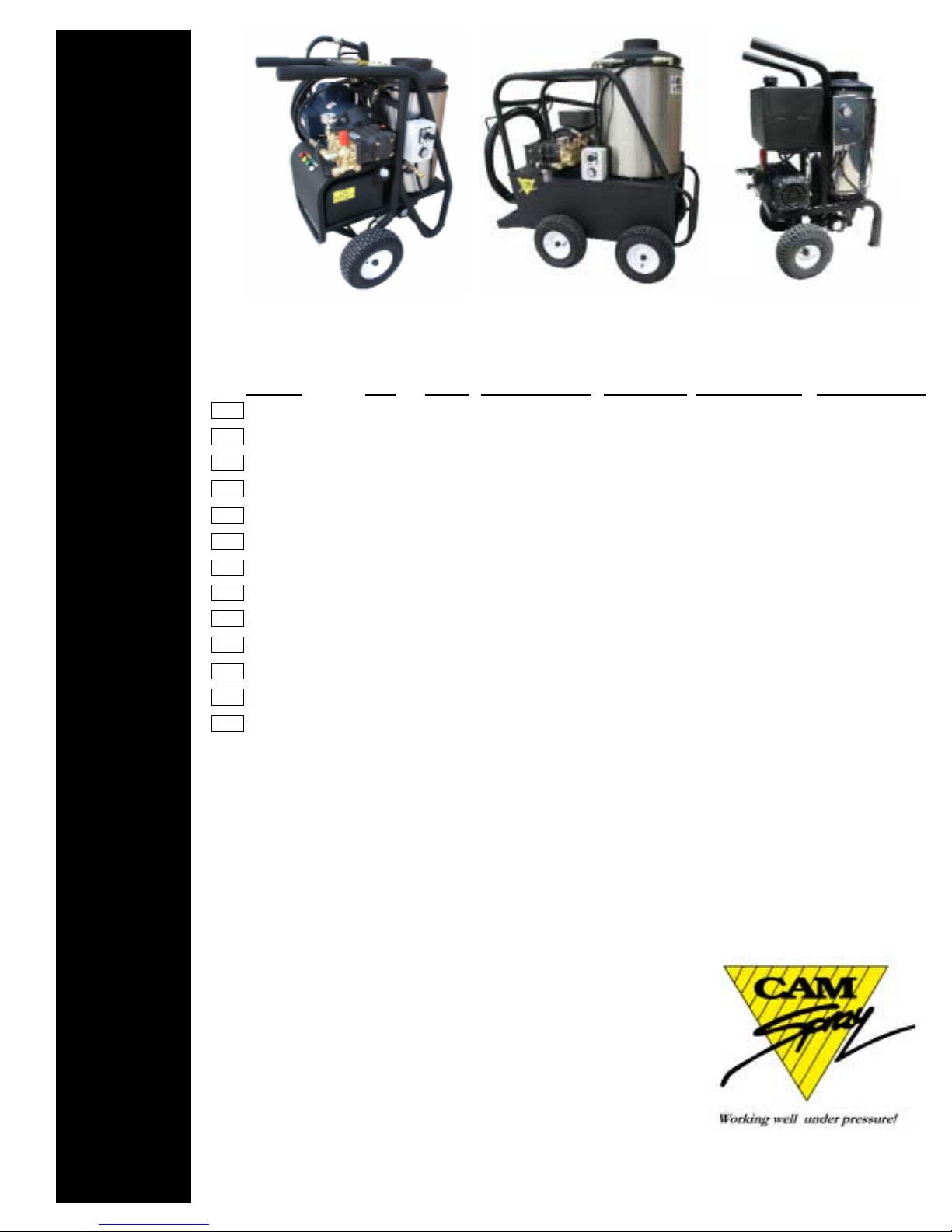
Images, from left, illustrate SH, QE & 1450SH-style pressure washers.
Page 2

Engine exhaust from this product contains chemicals known
to the State of California to cause cancer, birth defects, or
other reproductive harm.
Thank you
Thank you for selecting our products. Our personnel have proudly made every effort to ensure
that your new pressure washer is of the quality you expect. But things do occasionally go wrong.
This is why every pressure washer is covered by a limited warranty. Among other things, this warranty provides for the replacement of parts found to be defective during the operation of your new
pressure washer. Please note that the owner/operator has certain obligations under the terms of
the warranty. Be sure to read this manual for directions on proper installation, start-up, use, and
storage of your pressure washer.
Your new pressure washer was tested after production for proper pressure and flow. Please note
that this process will sometimes leave a water residue in the pump. The dealer you have purchased
your new machine from should review with you the proper installation, start-up, use, and storage.
Most ‘big’ problems occur when shortcuts are taken in one of these processes. If a problem occurs
that you need some assistance with, please feel free to contact us at the listing below:
Warranty Service Center
520 Brooks Road
Iowa Falls, IA 50126
1.800.648.6007
Be familiar with the model plate located on your machine. Have the model and code number with you
when you call for service. (Located on engine).
2
Please make note of Model Identification
Model #
Code #
Serial #
Always have this information when calling
Warranty Service Center.
Page 3
The manufacturer of this product agrees to repair or replace designated par ts that prove defective within the warranty period listed in the chart below. Specific limitations and exclusions apply. This warranty covers defects in material and
workmanship and not failure due to normal wear, depreciation, abuse, accidental damage, negligence, improper use, maintenance or storage. To make claim under the terms of the warranty, all parts said to be defective must be returned to a designated Warranty Ser vice Center for war ranty inspection. The judgments and decisions of the factory-authorized personnel
concerning the validity of warranty claims are final.
Many components are covered by warranties given by their respective manufacturers. These warranties pass through to the
end user. As a factory authorized and trained warranty ser vice center the factory will honor the ter ms of all component
warranties and satisfy claims of the appropriate warranty provisions.
Normal wear items include but are not limited to: hoses, nozzles, filter, valves, seals and are not covered by this warranty.
This warranty is in lieu of all other warranties, express or implied, including without limitation any warranties of
merchantability or fitness for a particular purpose and all such warranties are hereby disclaimed and excluded by the
Manufacturer. The Manufacturer's warranty obligation is limited to repair and replacement of defective products as provided herein and the Manufacturer shall not be liable for any further loss, damages or expenses, including damages from shipping, accident, abuse, acts of God, misuse or neglect. Neither is damage from repairs using par ts not purchased from the
Manufacturer or alterations performed by non-factory authorized personnel. Failure to install and operate equipment
according to the guidelines put forth in the instruction manual shall void warranty.
Manufacturer Warranty Period and Details
AR Pump 2 year 1 year on Pump/Motor units
Cat Pump 5 year on 2SF and 4SF models
2 year on 5DX models
General Pump 5 year on pumps
Lifetime on brass manifold against freezing
1 year on the aluminum manifold
1 year on Pump/Motor units
Udor Pumps 5 year
Briggs and Stratton 1 year on standard engines
2 year on Intek and Vanguard products
Hatz Diesel Engines 1 year
Honda Engines 2 year on GX series Engines
2 year on GC products for personal use
90 days on GC products in commercial use
Robin Engines 2 year
Baldor Electric Motors 1 year from date of purchase
Leeson Electric Motors 1 year from date of purchase
Burners 1 Year from date of purchase
Hot Water Coils 5 year from date of purchase
Machine Frame 1 year from date of purchase
Accessories:Includes tips, guns, wands, hoses, injectors, unloaders, sandblasters, flat surface cleaners, hose
reels, turbo nozzles, drain nozzles, brushes, foamers, GFCI units, thermal relief, filters, tanks, etc. 90 days
Statement of Warranty
Page 4
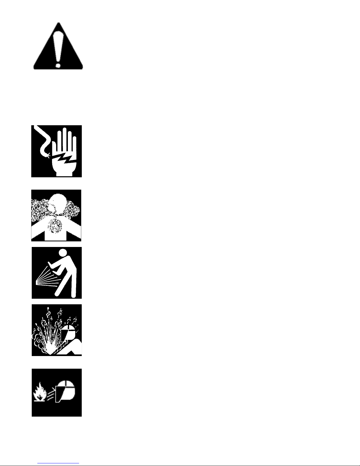
WARNING
The following warnings must be followed.Failure to follow these warnings could result in
serious personal injury or death!
Never allow children or untrained personnel to operate machinery.
Gun kicks back--hold with both hands.
Electrical equipment can cause shock and sparks.
Do not bypass or remove the grounding prong in any electrical plug.
Keep electrical plugs, connections, and cords out of water and moisture.
Disconnect from power source before servicing.
Inspect and repair damaged or exposed electrical components prior to use.
Never splice electrical cords on pressure washers.
Be sure electrical service is adequately sized for the equipment.
Exhaust fumes contain harmful gasses.
Exhaust gasses can cause death or serious injury.
Use only in well ventilated areas or vent the exhaust to the outside.
High pressure water can cause death or serious injury.
Warning--high temperature water.
Wear protective clothing and face shield.
Do not direct water stream toward self or others.
All hoses should be secured in the lines to be cleaned at least five feet.
Pressurized fluid streams and ruptured pressure vessels can cause death or serious
injury.
High pressure fluid can create a high pressure stream or ruptured vessel.
Wear a safety face shield.
Relieve pressure before servicing.
Do not modify, repair, or rework vessel or change safety relief or pressure setting.
Do not direct stream toward self or others.
Fire can cause death or serious injury.
Kerosene, fuel oil, and gasoline will bur n when ignited.
Wear face shield and protective clothing.
Do not expose fuel to flames, sparks, or other sources of ignition.
Use in well ventilated area or vent to outside area.
Save these instructions
3
Page 5

Initial setup and operation of your new pressure washer
When you receive your pressure washer, be sure you check for concealed freight damage. Any
damage should be noted with the delivering carrier. If you have any questions related to freight,
call the 800 number listed in the front of the manual.
Check all oil levels in the pump or engine, if applicable. Failure to check all levels will result in
equipment damage. Most pumps are shipped with oil from factory and the crankcase are sealed,
you may have to remove a shipping plug and install a dipstick in the pump.
Most engines are
shipped without oil, be sure to check these oil levels.
Your water supply must provide water to the equipment that exceeds the Gallon Per Minute
(GPM) rate of your machine. You can check your GPM by using a five gallon bucket and a
timer. If your machine is five GPM or less and the bucket fills in less than a minute you have
adequate supply. Some systems are effected by things like washing machines, livestock watering systems, and flushing toilets. Be sure the supply is still adequate when these operations are
taking place. The water temperature cannot exceed 145 degrees Fahrenheit. Water pressure
should not exceed 60 PSI.
Failure to secure adequate water supply will result in pump
damage. Do not run pump dry.
Your water should not contain particles larger than 80 microns. Although there are small filters
installed on pressure washers that filter the water, they can only filter poor quality water for a
short period of time before they clog. Clogging would result in damage to the machine.
Therefore you should insure no sand or scale particles are present in the water supply.
Hook a garden hose from the hydrant to the machine, when doing this be sure to check the
inlet water filter or screen. This hose should be at least 5/8’ diameter and a length at least 15
feet. This 15 foot length helps isolate the water supply from pulsations from the pump.
Many
states require a Vacuum Break or backflow preventer be installed at the hydrant
,
before the garden hose, to insure the water source cannot be contaminated. Be sure to check
local and state regulations upon installation.
Turn on the water supply and open the trigger gun, this will purg e all the air from the system.
Look for water leaks and stop any leak found. Leaks can cause erratic pump behavior.
Turn equipment off and allow time to cool before refueling. Fill the bur ner tank labeled ‘fuel’.
Be sure the fuel is clean and free from moisture and particles.
Use only No. 1, No. 2 or
kerosene, no other fuel should be used!
There is a fuel filter in the line. Check this filter
prior to operation. Do not run fuel pump dry, doing so will damage the fuel pump.
Prior to starting the motor, check the oil in the pump. Be sure it is at the proper operating level
and that the correct oil is being used. Check the pump breakdown for the proper type of oil.
Inspection
for freight
damage
Inspection
of oil levels
Water supply
Water quality
Supply hose
Purge air
Burner fuel
Pump
4
Page 6

Shut down procedure
Initial setup and operation of your new pressure washer, cont.
The pressure was set at the factory during the testing procedure, no adjustments to the machine
should be required for operation. During operation the burner may cycle on and off. The
adjustable thermostat may be set to desired temperature. Water temperature will not ex ceed 190
degrees, the safety switches will shut the burner down.
During operation do not leave the
machine running for more than two minutes without the trigger gun being pulled.
Although your machine has a by-pass v alve on it and may have a thermal relief system, this can
cause extensive pump damage.
If machine will not be discharging water for more than
two minutes, shut the machine off.
Your machine is supplied with interchangeable spray tips. The colored tips are for high-pressure rinse at different spray angles. The red tip sprays at zero degrees; yellow, fifteen degrees;
green, twenty-five degrees; and white, for ty degrees. T he yellow tip is used for most standard
applications. Be sure the quick coupler is fully engaged before pulling the trigger
gun. Failure to do so may result in the tip becoming a projectile and may be lost and damage
to property and persons may occur.
Your pressure washer is supplied with a downstream chemical injector. The 1/4” clear vinyl
tube is to be inserted into the desired chemical to apply. T he chemical injector will only open
up and allow chemical into the line when the forward handle (see wand breakdo wn page 10) on
the wand is turned counter clock wise.This enables the pressure to drop to approximately 250
PSI and draw chemical, this is a valve that allows the water to flow through the wand and
through the chemical tip. The rate of injection can also be set by turning the knob that the
clear vinyl tube attaches to.
Be sure to flush injection system with clear water after use.
If an accurate injection rate is desired, use this formula.
(GPM x 128) / ounces drawn in one minute = x: 1
IE: If a 2.0 GPM machine draws eight ounces of chemical in one minute: 2 x 128
8 = 32:1
1. Turn off the power switch on the burner. Continue to run the pressure washer and pull
the trigger to circulate water through to cool the coil.
2. After several minutes when water is cool, shut off the pressure washer motor.
3. Shut off water supply and disconnect garden hose.
4. Be sure to double check for water leaks or oil leaks that should be repaired before the next
operation.
If you are going to store the machine for extended period of times in cold climates be sure to
winterize the equipment. A fifty percent anti-freeze solution may be drawn in through the inlet
of the pump using a short remnant of garden hose. This fluid should be run through the pump
and coil. When the f luid is discharged from the coil discharge your machine is winterized.
Do
not allow machine to freeze.
The pump oil should be changed after the first fifty hours of operation, then every year for
average service or more frequently for extensive use or hostile environments (dusty or high
moisture).
During
operation
Interchange-
able tips
Chemical
injector use
Calibration
Storage
Winter
storage
Pump
5
Page 7

Troubleshooting: common problems and solutions
Cause
-Switch in ‘off’ position
-Machine not plugged in
-GFCI tripped
-Overload on motor tripped
-Circuit breaker tripped
-Water supply not turned on
-Plugged nozzle on wand
-Trigger gun off or malfunctioning
-Plugged spray nozzle
-Inlet screen is plugged
-Insufficient water supply
-Unloader valve stuck open
-Plugged inlet or discharge hose
-Use of additional lengths of hose
-Partially plugged spray nozzle
-Worn nozzle
-Soap (low pressure tip installed)
-Restricted or leaking water hose
-Cavitation (inadequate water supply)
-Worn pump packings
-Fouled inlet or discharge valves
-Broken valve spring
-Worn or restricted unloader valve
-Restricted discharge
-Valve on gun/wand not open
-Injector valve not turned on
-Discharge hose too long
-Clogged injector pick-up hose
-Clogged injector
-Worn plungers or packings
-All valves fouled
-Unloader valve seat fouled
-Leak in trigger or discharge
-High humidity or direct water spray
-Worn seals
Malfunction
PPrreessssuurree wwaasshheerr wwiillll nnoott rruunn
UUnniitt rruunnss bbuutt nnoo wwaatteerr ddiiss-
cchhaarrggeess
LLooww nnoozzzzllee pprreessssuurree
SSuurrggiinngg pprreessssuurree oorr ddrroopp iinn
pprreessssuurree
PPrreessssuurree aatt ppuummpp bbuutt llooww ddiiss-
cchhaarrggee pprreessssuurree aatt gguunn
CChheemmiiccaall iinnjjeeccttoorr nnoott wwoorrkkiinngg
pprrooppeerrllyy
WWaatteerr lleeaakkss ffrroomm ppuummpp mmaannii-
ffoolldd
UUnnllooaaddeerr ddooeess nnoott bbyyppaassss
UUnnllooaaddeerr ccyycclleess wwhheenn gguunn iiss
sshhuutt ooffff
WWaatteerr iinn ccrraannkkccaassee
Remedy
-Turn switch to ‘on’ position
-Plug machine into adequate service
-Reset GFCI
-Allow automatic overload to cool or push the
reset button located on motor to reset
-Reset circuit breaker in main panel
-Turn on water supply
-Remove, clean, or replace nozzle
-Remove, repair, or replace trigger gun
-Remove nozzle and clean or replace
-Remove filter and clean or replace
-Secure adequate water supply
-Disassemble and clean; repair or replace
-Flush or replace hoses
-Reduce discharge hose length.
-Remove nozzle and clean or replace
-Remove and replace nozzle
-Remove and install one of the nozzles
-Check inlet hose and filter; clean or replace
-Secure adequate water supply
-Inspect and replace worn packings
-Inspect valves and clean or replace
-Inspect and replace valve spring
-Inspect unloader and repair or replace
-Check for discharge obstructions in injector,
hose, wand, and unloader
-Open valve by turning forward handle counterclockwise. (see wand breakdown page 10)
-Turn on injector by turning fitting on injector
-Reduce hose length or reposition injector to
within forty feet of trigger gun
-Remove and clean or replace
-Disassemble, clean, and reassemble
-Inspect and replace
-Inspect valves and clean or replace
-Inspect and clean or replace
-Inspect leaking fittings and repair or replace
-Reduce oil change intervals
-Replace seals
Despite the complexity of your power washing equipment, a number of common complaints stem from relatively simple problems. With guidance, the user can identify and remedy many common problems.
Always disconnect the power supply before attempting to service any equipment.
6
Page 8
Cause
-Burner switch in ‘off’ position
-Burner switch on but pump switch off
-Inadequate fuel supply
-Plugged fuel filter
-Trigger gun not pulled on
-Thermostat turned off
Malfunction
WWiillll nnoott pprroodduuccee hhoott wwaatteerr
Remedy
-Turn burner switch on
-Turn on pump switch (must be on for heater to
operate properly)
-Fill tank with kerosene, no. 1 or no. 2 diesel
-Replace fuel filter
-Pull trigger gun (water flow must go through
coil to operate heater)
-Turn thermostat dial to the ‘on’ position
Troubleshooting: common problems and solutions, cont.
For problems beyond those listed, refer to flow chart included with the burner breakdown.
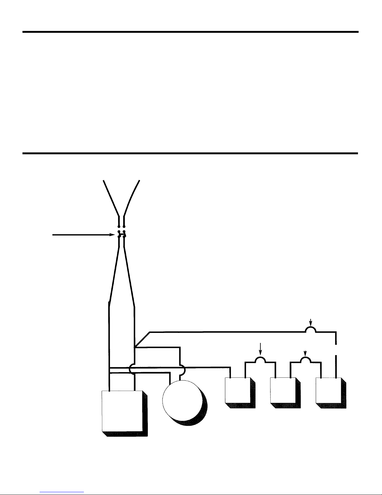
AC Wiring Diagram
7
Transformer
Burner Motor
Fuel
Solenoid
Yellow male/Yellow female
Black female/Black male
Black wire
Black wire
Terminal 4
Line(black)
Line (white)
Terminal 1 Terminal 2
White wire
White wire
Black
wire
Temp
Switch
Flow
Switch
Power switch
Terminal 3
Orange male/Orange female
Page 9
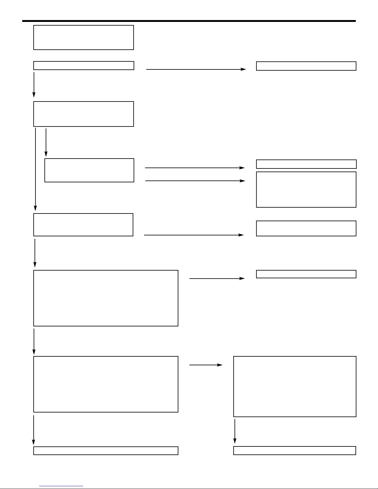
Burner troubleshooting
Pump is running
Burner is running
Burner will not fire
Check fuel supply
Check transformer by arching an
insulated handle across contacts.
Disconnect power supply. Is fuel filter
clean? Does fuel flow freely? Is fuel at
bleeder on fuel pump?
Test fuel solenoid circuit:
1. Disconnect power supply
2. Unplug black & yellow leads
3. Plug black female into yellow male
4. Connect power supply
5. Start machine using normal procedure
Does burner fire?
Test Thermostat circuit:
1. Disconnect power supply
2. Connect the yellow leads together
3. Plug orange male into black female
4. Connect power supply
5. Start machine using normal procedure
Does burner fire
Replace thermostat
While machine is running, disconnect
fuel line at burner housing. Is fuel
flowing?
Fill fuel tank
Replace transformer
Check for plugged burner nozzle and
properly spaced electrodes. If ok,
replace electrodes.
Clean or replace filter. Clean or look
for pinched hoses.
Clean or replace fuel solenoid
Test flow switch circuit:
1. Disconnect power supply
2. Connect the black leads together
3.Plug the yellow male into the orange
female
4. Connect power supply
5. Start machine using normal procedure
Does burner fire?
Tank empty
Tank full
Transformer does not operate
No
No
No
Transformer operates
No
Yes
Yes
Yes
Yes
Clean or replace flow switch
Yes
8
Page 10
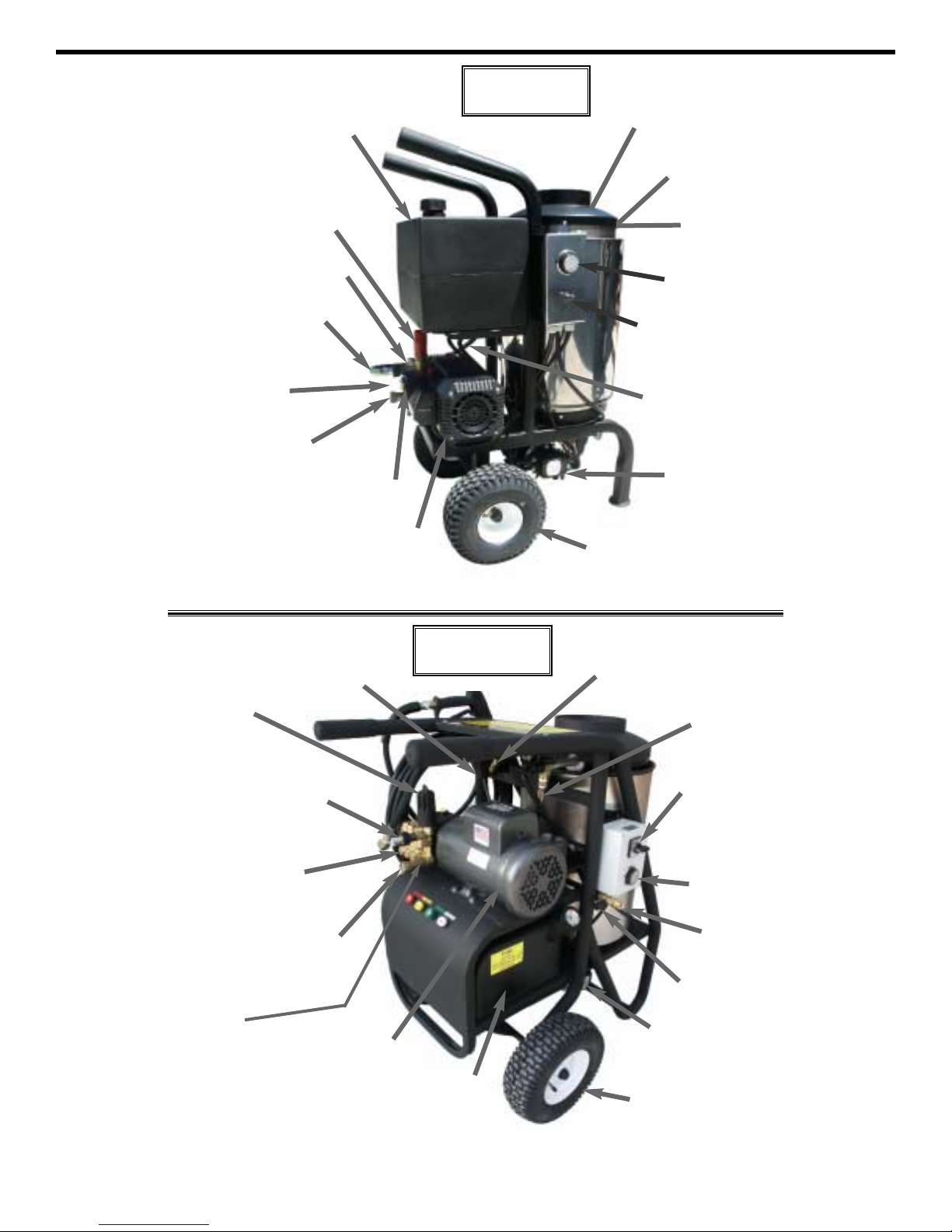
Tank, FFuel ww/cap
(540175)
Filter, ffuel
(509117)
Unloader aassly
(see pump breakdown)
Unloader aassly
1000-20005
(See pump breakdown)
2000-3000 (UB-22)
Thermal vvalve
509309
Thermal vvalve
509309 (3/8” 1000psi)
509306 (1/2” 2000-4000psi)
Coupler ffittings
527810 F x F
527715 M x F
Coupler ffittings
527810 F x F
527715 M x F
Inlet ffitting
GEN 680006
Inlet ffitting
GEN 680006 (1000-20005psi)
GEN 100649 (2000-4000psi)
Motor
521308.1 (2hp)
509992.4 (3hp)
509992.2 (5hp small)
521320 (5hp large)
510001 (7.5hp)
Pump aassly
TP2530X34UI (1000,1500)
TP2530J34UI (20005)
MD4.0/20U (2000,3000)
Tank, ffuel
540172
Cap, ffuel
524374
Wheel
524518
Cap, wwheel
509570
Switch, mmotor
93507000
Pump/Motor
GEN 190399
Wheel
524518
Cap, WWheel
509570
Switch, bburner
526300
Hose, jjumper
(pump/coil) 509096
Burner aassly
CAM 103
Thermostat
540116.1
Thermostat
540116.1
Injector, cchemical
509555 (not shown)
Pop ooff vvalve
515500 (not shown)
1450 SSHDE
1000-33000 SSH
Hose, jjumper
(pump/coil)
509096 (24” x 3/8”)
509097 (18” x 3/8”)
Pop ooff vvalve
515500
Flow sswitch
GEN 100809
Injector, cchemical
509556
Switch, 33 wway
526340(1000)
526342(1500,20005)
526344(2000,3000)
Coupler ffitting
527715 M x F
Reference
Burner aassly
CAM104 (1000)
CAM204 (1500-3000)
Coupler ffitting
527715 M x F (not shown)
Flow sswitch
GEN 100809
Page 11
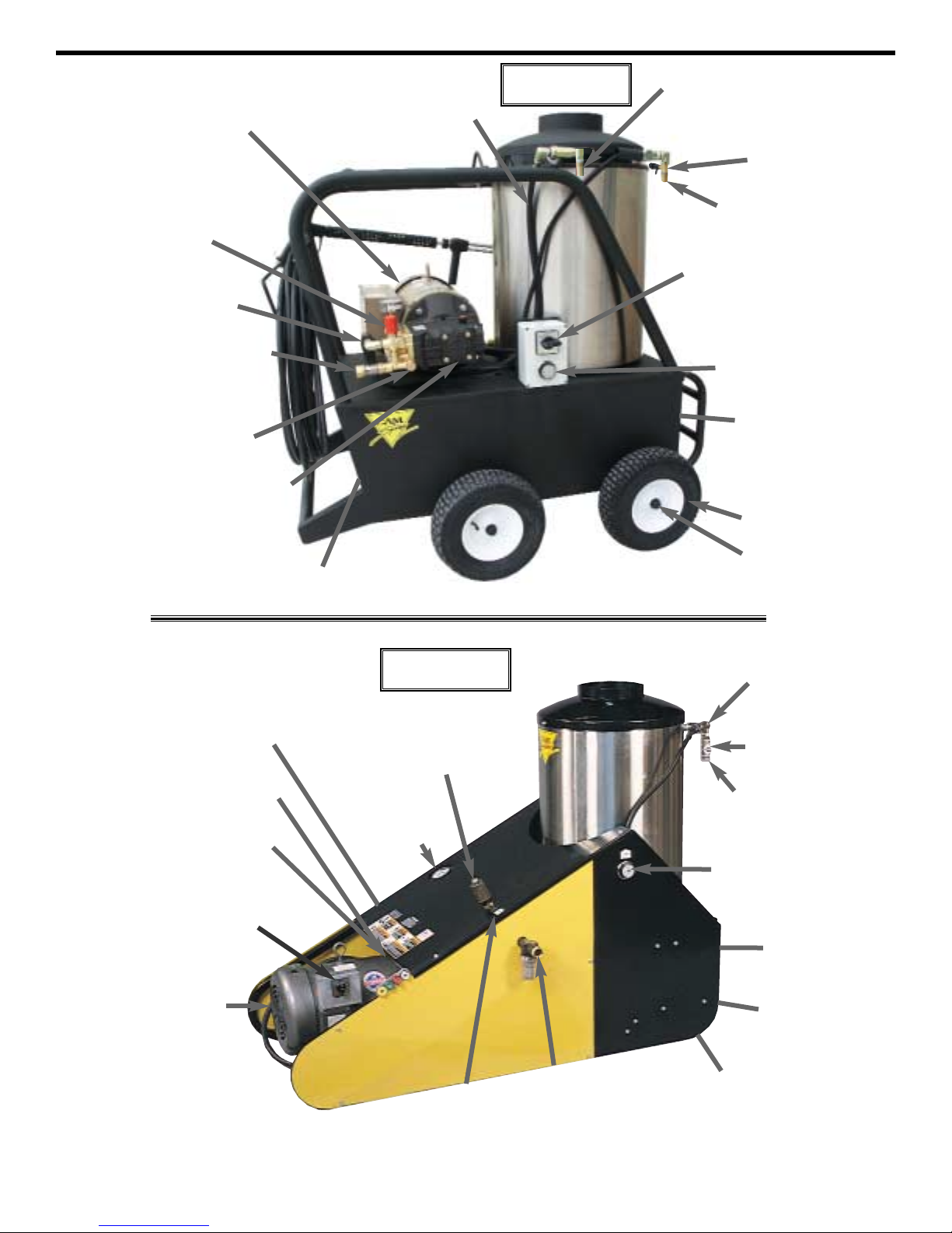
Reference
9
Flow sswitch
GEN 100809
Inlet ffitting
GEN 680006 (1000-1500psi)
GEN 100649 (2000-4000psi)
Motor
521308.1 (2hp)
509992.4 (3hp)
521320 (5hp)
510001 (7.5hp)
Pump aassly
TP2530X34UI (1000,1500)
MD4.0/20-U (2000,3000)
XWA4G40N (4000)
Switch, 33 wway
526340(1000)
526342(1500,20005)
526344(2000,4000)
Wheel
524518
Cap, wwheel
509570
Burner aassly
CAM104 (1000)
CAM401 (1500-4000)
Thermostat
540116.1
Pop ooff vvalve
515500 (1000-3000)
CAT 33961 (4000)
Tank, ffuel
540178
Unloader aassly
UB-22 (2000,3000)
YU2140 (4000)
Hose, jjumper
(pump/coil)
509094(30”)
Injector, cchemical
509555
Coupler ffitting
527715 M x F
1000-44000 QQE
Injector, cchemical
509555
Coupler ffitting
527715 M x F
Thermostat, aadjustable
540116.1
Burner aassly
CAM 201
Switch, mmotor
526312 (5hp)
526324 (7.5hp)
Motor
521320 (5hp)
510001 (7.5hp)
Pump aassly
RKA4G20E-F17 (2000)
MD4.0/20-U (3000)
Switch, bburner
526300
Pop ooff vvalve
515500
Flow sswitch
540110 (not shown)
Inlet ffitting
GEN 100649
Tank, ffuel
540091
Thermal vvalve
509306 (1/2”)
Fuel sseparator
510562
2000-33000 TTR
Thermal vvalve
509306
Unloader aassly
515810
Gauge
520902
Page 12
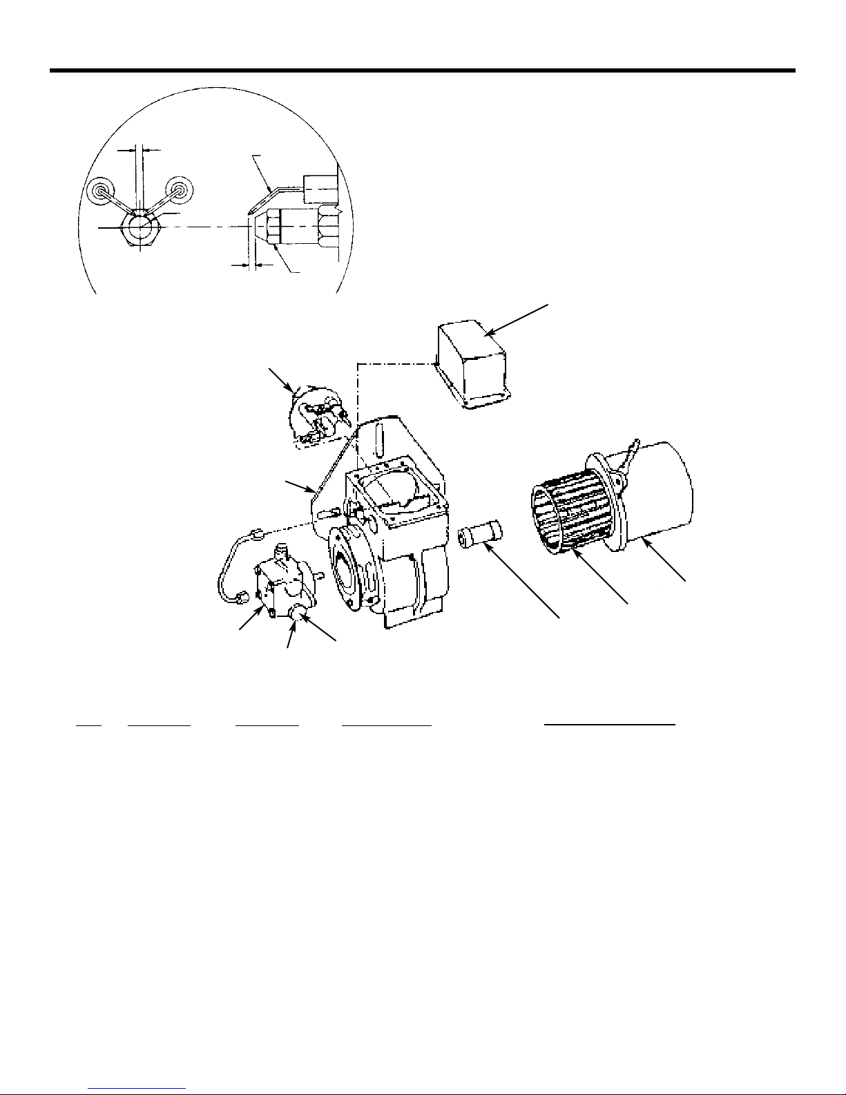
Model AFG 120 Volt/230 Volt 60 Hertz Burner
Electrode adjustments
5/32
1/4
Electrode
Nozzle
5/32
No.
1
2
3
4
5
6
7
8
9
N/S
115 Volt AC
P
art No.
B21844U
B21755U
B21877U
B5780
540138
B2456U
B2454
B2999
B3616
B51843U
Description
Fuel pump with valve
Valve coil
Valve stem
Electrode set
Transformer
Motor
Coupler
Blower wheel
Gasket
Strainer kit
230 Volt AC
P
art No.
B21844U
B21756U
B21877U
B5780
540138.1
B21174
B2454
B2999
B3616
B51843U
8
6
9
5
7
3
1
2
4
10
Burner assembly
1450SH 115V - (CAM 103)
SH frame 115V - (CAM 104)
SH frame 230V - (CAM 204)
TR frame 230V - (CAM 201)
Q frame 115V - (CAM 104)
Q frame 230V - (CAM 204)
Page 13
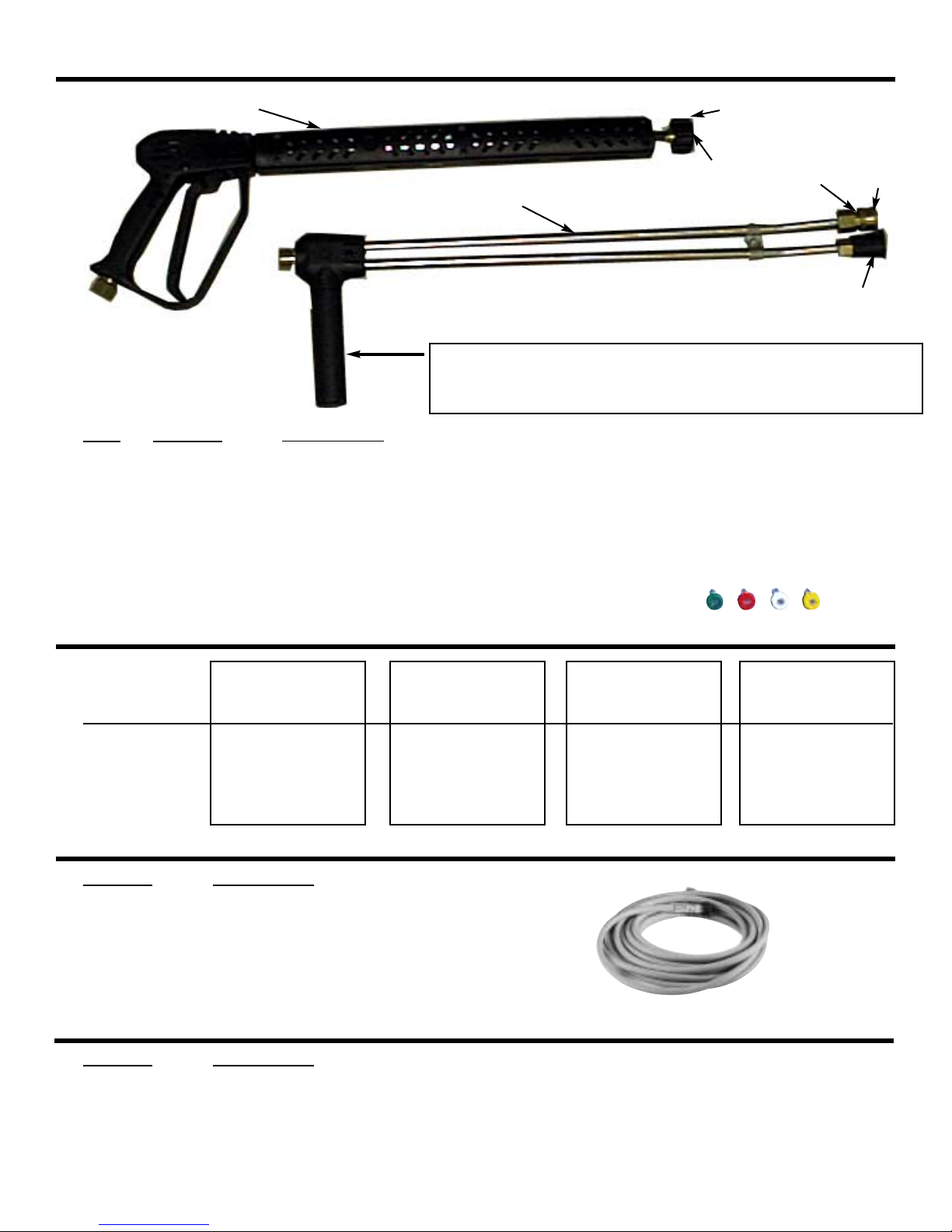
Wand breakdown
Replacement tips for all units
Replacement Hoses
Hose Extensions (with coupler ends)
Part no.
AR AL200
542002
510100
510065
527800
510065
4030
1/4 meg
P
os.
1
2
3
4
5
6
7
Model
Red
Yellow
Green
White
P
art no.
509073
509074
509080
509085
509081
P
art no.
527650
527651
527653
527660
Description
20’ x 3/8”
30’ x 3/8”
40’ x 3/8”
50’ x 3/8”
100’ x 3/8”
Description
20’ x 3/8”
40’ x 3/8”
50’ x 3/8”
100’ x 3/8”
1450SHDE
00035 Q Meg
15035 Q Meg
25035 Q Meg
40035 Q Meg
1000, 20005,
and 3000 SH,
QE, and TR
0004 Q Meg
1504 Q Meg
2504 Q Meg
4004 Q Meg
Forward ggrip/soap ccontrol vvalve.
Activates chemical injector by lowering pressure and allowing
water to go through soap tip. (Turn handle counter clockwise)
1500SHDE
0005 Q Meg
1505 Q Meg
2505 Q Meg
4005 Q Meg
2000 SH, QE,
and TR
0006 Q Meg
1506 Q Meg
2506 Q Meg
4006 Q Meg
Description
Gun section of wand
Dual wand 1 1/2
“O” ring for QC and TF
1/4 quick coupler
Twistfast coupler socket
Quick coupler socket
Soap tip
11
1
2
7
6
5
3
4
 Loading...