

Page 1
-20ºC
÷
+55ºC
9 V DC
÷
14 V DC
SMA
ANTENNA
CONNECTOR
IP65
8
CHANNELS
BNC
VIDEO
UTP
VIDEO
5,8
GHz
25
mW
FM
PAL
NTSC
VIDEO:
10
CHANNELS
869
MHz
300
mW
GFSK
RS-485
DATA:
Operating manual
Warranty Terms
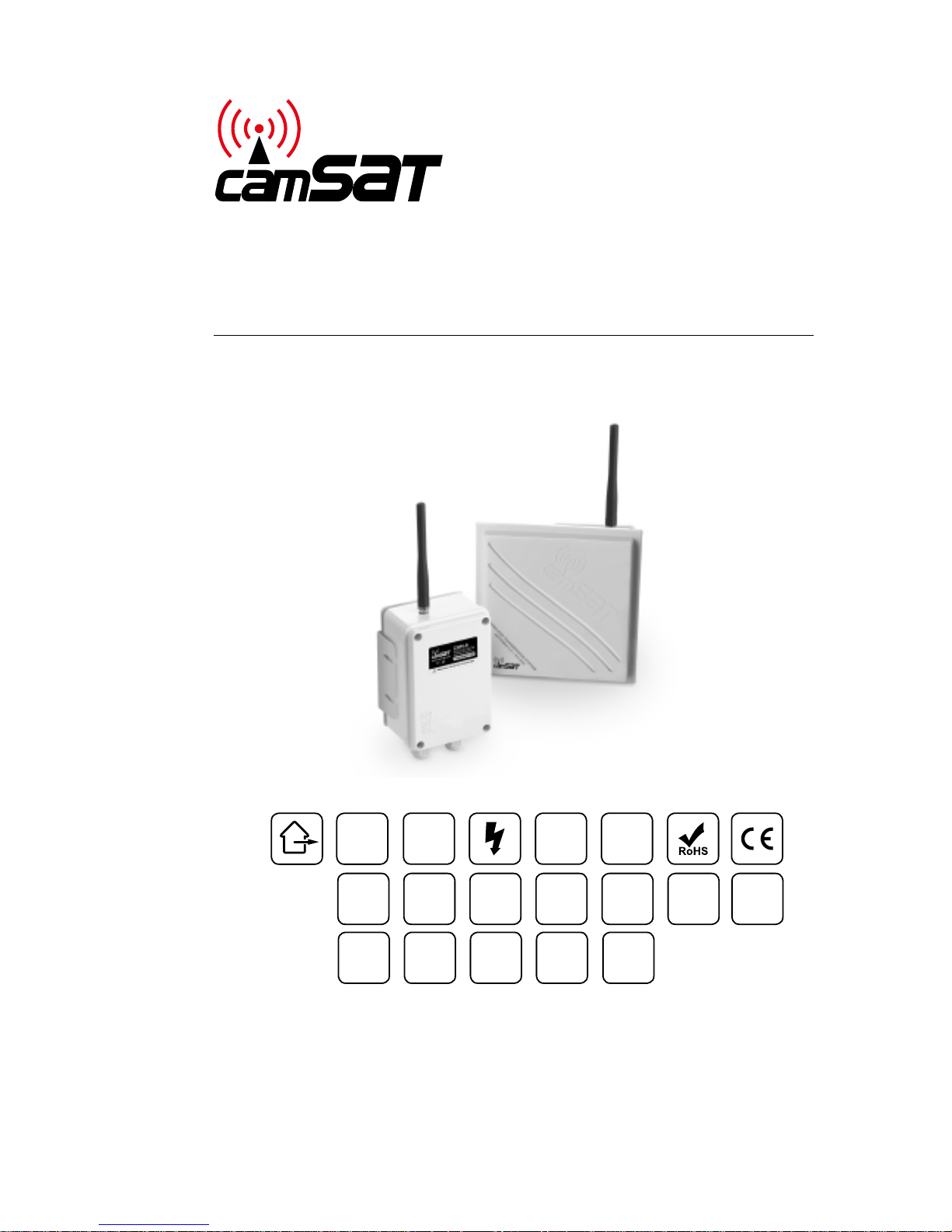
CAM-9
Wireless system for simultaneous transmission of
video, audio and control for PTZ cameras
Page 2

Table of contents
Product features..................................................... 4
Kit contents.......................................................... 4
Recommendations .................................................. 5
Technical data . . . . . . . . . . . . . . . . . . . . . . . . . . . . . . . . . . . . . . . . . . . . . . . . . . . . . . . 6
Switch settings ...................................................... 8
Installation .......................................................... 8
Basic settings........................................................ 9
Operating the dip-switch............................................. 9
Video transmission settings ......................................... 9
Data transmission settings........................................... 9
Setting the data transmission operating channel ..................... 9
Advanced settings................................................... 11
Procedure for assigning transmitters to the receiver memory . . . . . . . . . 11
Setting the video operating channel remotely ........................ 12
Setting the data transmission parameters remotely .................. 12
Advanced settings................................................... 12
Testing the data link................................................. 12
Removing a transmitter from the CAM-9 Rx receiver memory ....... 13
Restoring the device to default settings............................ 13
General warranty terms............................................. 14
Device disposal ...................................................... 15
Page 3
4 5
Product features
The CA M-9 ki t is an in tegrated t ransmission sys tem com pris ed of
a modul e for vi deo tr ansmi ssion and dat a transmis sion to a nd from
indus trial came ras in a s ingle c ompac t cas e.
Kit contents
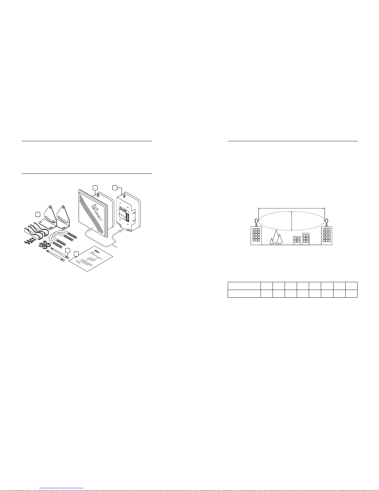
The kit includes:
1
3
5
4
2
ANTENNA SIDE
1. Video/audio receiver (Rx) with an IP65 antenna x 1 pcs.
2. Video/audio transmitter (Tx) with an IP65 antenna x 1 pcs.
3. 35-50mm pole mount x 2pcs.
4. 869 MHz antenna x 2 pcs.
5. Operating manual, warranty terms
Recommendations
1. Larger systems consisting of a few kits should be started up and set up
one after another, i.e. the power supply should be connected to the next
kit only after the previous kit has been set up precisely.
2. It is recommended to install CAM-9 receivers at least 7 m away from
digital receivers (CDS-5021, CDS-5IP and other).
3. It is not permitted to power devices without antenna cables screwed
into the SMA connectors.
In orde r to ensu re a stable ra dio ra nge, the ante nnas ha ve to see
each other optically. One hundred percent optical visibility should be
provi ded in t he rs t Fresn el zone.
d - 7,2 m
D - 1 km
At the freque ncy of 5.8 GHz and the dis tance of 1 km, f ree sp ace wi th the
diame ter of a t leas t 7.2 m should be provi ded fo r the ra dio beam.
A few ready-made ca lcula tion s for CA M-9 ar e pres ented below
Distance [km] 0.4 0.8 1 1.2 1.6 2 2.5 3
Diameter [m] 4.5 6.4 7.2 7.9 9.1 10.2 11.4 12.5
Larg er dire cti onal an tennas can be plugged into t he con nectors (R x)
in orde r to extend th e rang es.
Page 4
6 7
Technical data
DANE AUDIO-WIDEO
Frequency
869 MHz 5.8 GHz
Numbe r of oper ating chann els 10 8/16*
Radio link modulation GFSK FM
EIRP radiated power 300 mW 25 mW
Receiver sensitivity −118 dBm@1200 bps /
−114 dBm@960 0 bps
≤ −85 dBm
Antenna connectors SMA-RP F 50 Ω SMA-RP F 50 Ω
Antenna characteristics
omnidirectional
36 0° H/15 °V
Tx: direc tional –
30°H/30°V
Rx: direc tion al –
20°H/20°V
Antenna gain 2.15 dBi Tx: 5 dBi; Rx : 19 dBi
Device range 3 km (with the option to e xtend the r ange to 5 k m)
Video interface BNC 1Vp- p (75 Ω) + screw t erminal for U TP (100 Ω)
Video format PAL/N TSC
Audio interface Screw ter minal , ster eo audio in/out 2Vp-p (2 kΩ)
Audio frequency response 50–15000 Hz
Data interface RS-485 (A+, B−)
Supported protocols Ale c, Ar itech, Baxal, Bosch Biph ase (wit h addi tional
conve rter), COP-1, COP-2, D-Max , Dyna color, Ganz,
Kalat el, LG, L ongcomit y, Molyn x, Multix, P anaso nic,
Pelco D, P elco P, Sams ung, Sa ntac hi, Sensorm atic ,
Ultr ak, VCL , Vicon and ma ny other
Data format 8 n1, 8 o1, 8 e1
Data transmission rate 1200, 2400, 4800, 96 00, 19200 [bp s]
Power supply voltage 9–14 V **
Maximum power consumption 310 mA* *
Case pr otec tion class IP65 (external application)
Operating temperature from −20°C to +55°C
Warranty 2 years
Certicates CE
Device external dimensions Tx: 152 × 103 × 60 [mm]; Rx: 164 × 164 × 80 [mm]
*The num ber of usable cha nnels depends o n the regulatio ns in the specic co untry. The
use of 8 cha nnels is p ermitt ed in the Eur opean Union cou ntries, while i n many countries
outsid e of the Union 16 channe ls can be used.
**We reco mmend us ing high q uality p ower supplies (h igh-ecie ncy trans former-based
or impul se ones, with low cu rrent ripplin g), with cur rent eci ency of at least 40 0 mA
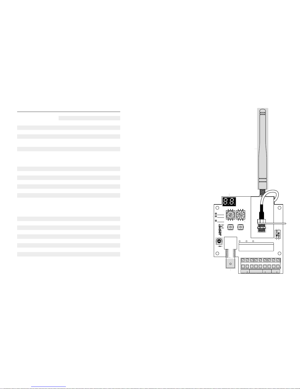
[A] - 869 MHz antenna
[B] - L ED display
[C] - PO WER dio de
[D] - L INK dio de
[E] - diode signalling data transmission
[F] - rotary switch for se tting
video channels
[G] - rot ary s witc h for se tting data chann els
[H] - S ET butt on
[I] - ENTER button
[J] - on/o s witch for the 120 Ω
termin ator on the RS -485 line
[K] -
changing the operating frequency band
[L] - a djust ing th e vide o signa l level
The video signal can be connected through:
[M] - v ideo coaxial cabl e
[N] - UTP t wis ted pair cabl e
[O] - aud io sign als connect or
[P] - R S-4 85 signals
connec tor
[R] - +12 V DC
power supply
7
6
5
4
3
2
1
0
9
8
A
9
8
7
6
5
4
3
2
1
0
F
E
D
C
B
ON
1 2
VIDEO CH.
SET ENTER
BNC VIDEO
V-Reg
DATA CH.
CHANNELS
PWR
T×D
R×D
LINK
UTP VIDEO AUDIO RS48 5 SUPPLY
- AL B-R GND GND 12
WIRELESS VIDEO & TELEMETRY
BASIC: F1 - baud rate set | F 2 - data format s et
ADVANCED: F3 - pairing | F4 - video chann el set
F5 - testing | F6 - remov e TXs (RX only)
MENU
TERM 120Ω
ON/OFF
OFF - EU
ON - non EU
CAM-9
www.camsat.com
RX-M RX-S TX
-
A
B
C
D
E
F
G
I
H
JK
L
M
N O P R
Page 5
8 9
Switch settings
Installation
1. Fasten the transmitter and receiver to a stable pole with the mounts.
2. Screw the 869 MHz [A] antennas into SMA antenna connectors at the
top of the case.
3. Connect the video cables with the coaxial cable [M], or the UTP twisted
pair cable [N].
4. Connect the audio cables [O] (right channel, left channel,
signal ground).
5. Connect the RS-485 cables [P] (A+, B-).
6. Connect the 9-14V DC power supply [R].
Basic settings
Operating the dip-switch
SWI TCH 1 [J] – enables / disa bles t he 120 Ω resis tor (termina tor) in
parallel wi th the R S-4 85 int erf ace te rmina ls. This resi stor should always
be added at the end of ev ery R S-4 85 line t o avoid inter fere nce. In o rder
to enab le the resistor (RS-485 l ine ter minator), it sh ould be s et to th e
ON posi tion; in orde r to disa ble it , it should be se t to the O FF position.
SWI TCH 2 [K] – changes the frequency band for video signal
tran smiss ion. The devi ce can o pera te in tw o freq uenc y rang es:
5.733 – 5.866 G Hz (8 oper atin g chann els – ISM b and, p ermi tted w ithi n the
Europ ean Uni on) and 5.705 – 5.945 G Hz (16 operati ng channels – ca n be
used on ly in sel ected countries outsi de of the Europ ean Unio n).
In orde r to chan ge the f requ ency b and fo r video transmiss ion, us e swit ch
no. 2: OFF po siti on – 8 oper atin g channels, ON po siti on – 16 operating
channels (permi tted only in selected countries outside of t he EU).
Video transmission settings
Setting the video transmission operating channel
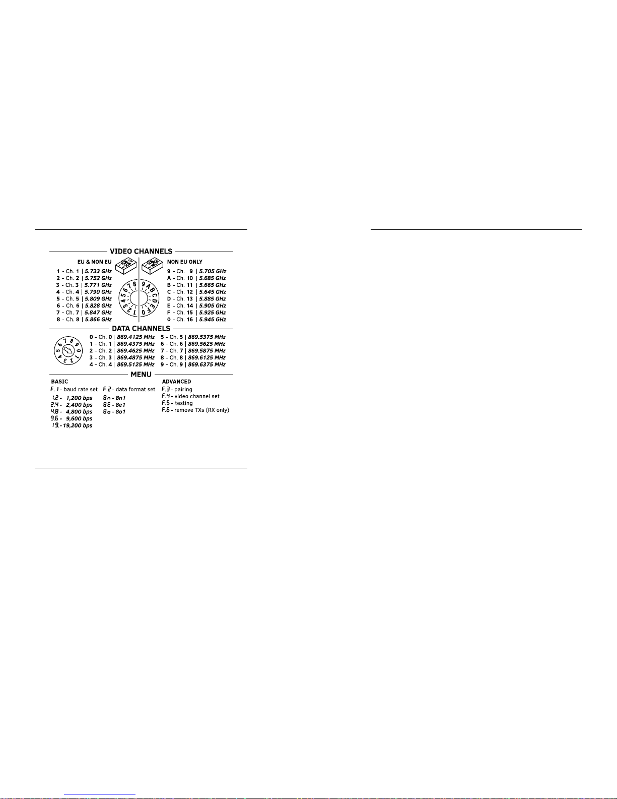
1. In order to set the video transmission operating channel, turn the rotary
switch, labelled “VIDEO CH.” [F], to the desired position.
2. The display will show the number of the currently selected channel.
3. After selecting the proper channel, the display will start blinking,
indicating that the settings are being saved to the device memory. Then,
the display will turn o by itself.
Data transmission settings
Setting the data transmission operating channel
1. In order to set the data transmission operating channel, turn the rotary
switch, labelled “DATA CH.” [G], to the desired position.
2. The display will show the number of the currently selected channel.
3. After selecting the proper channel, the display will start blinking, indicating that the
settings are being saved to the device memory. Then, the display will turn o by itself.
Page 6

10 11
Method f or setting the tr ansmis sion rat e and data f ormat
1. In order to get to the settings, enter the device menu by holding the
ENTER button [I] for three seconds (until appears on the display).
2. You can switch between the menu options (
, ,
) by pressing the
ENTER button [I] shortly.
3. To enter a specic submenu, press the SET button [H].
4. To exit a menu (return to the main menu), hold the ENTER button [I]
again for 3 seconds (until the display turns o).
Setting the transmission rate
In orde r to set t he transmission r ate, s elec t the ,
option from the menu. The d isplay will show the cu rren tly se t tra nsmis sion
rate in the following format: - 1200 bps; - 2400 bp s; - 48 00 bps;
- 9600 bps; - 19 200 bp s
Select the p rope r opti on wit h a shor t press of the ENTER b utto n
[I]
. To
conr m the selec tion , hold the SET butto n [H] for 3 seconds; the dis play
will start blink ing, in dica ting t hat th e settings a re being save d to the
device memo ry. The n, the device w ill re turn to t he main MENU.
Setting the data format
In orde r to set t he dat a form at, se lec t the option fro m the me nu. Th e
display will sh ow the c urrently s et dat a form at:
- 8n1; - 8o1; - 8e1
Select the p rope r opti on wit h a shor t press of the ENTER b utto n [I]. To
conr m the selec tion , hold the SET butto n [H] for 3 seconds; the dis play
will start blink ing, in dica ting t hat th e set tings a re being save d to the
device memo ry. The n, the device w ill re turn to t he main MENU.
Advanced settings
In orde r to use the advanced o ptio ns, devices o perating a t the same
build ing sho uld be paired t oget her. All th e CAM-9 Tx trans mitters sh ould
be assi gned to the CA M-9 M R x rece iver me mor y.
Procedure for assigning transmitters to the receiver memory
1. Select the option from the main menu in the receiver. Menu options
are selected by pressing the SET button [H] shortly.
2. The display in the receiver will show the number of transmitters
currently entered into memory. This value will blink, indicating that the
assigning procedure is active.
3. Select the option from the main menu in the transmitter. The value
on the display will start blinking. After a moment, the blue LINK diode
[D], will light up, indicating that the pairing procedure was completed
successfully. The identication number, received by each transmitter
in the network, will appear on the display. It should be noted down, in
order to identify that transmitter later. After a few seconds, the device
will return to the main menu.
4. The procedure from section 3 should be repeated for each CAM-9
Tx transmitter.
5. In order to end the assigning procedure, turn o the function in the
receiver by holding the ENTER button [I]. The device will return to the
main menu. The LINK diode [D] on the receiver will remain lit.
A properly conducted assigning procedure enables the following:
- setting the video transmission operating channels remotely (from the
CAM- 9 M Rx re ceiver leve l),
- testing l inks – bo th from the transm itt er and re ceiv er leve ls,
- setting the data tra nsmis sion parameters (data ra te, dat a form at)
remotely.
WARNING: Wh en tran smitters are as signed to a speci c receiv er and have
their id enti cation numbers (the LIN K diode is lit), th e function of se ttin g
the dat a transmis sion parame ters (rate and f ormat) and set ting the vid eo
transmissi on operati ng channel is locked in t hem. All these func tions are
congured rem otely, from the CAM -9 M Rx receiver leve l.
Page 7

12 13
Setting the video operating channel remotely
In orde r to set t he vid eo transmis sion opera ting channe l (for a spe cic
tran smit ter) rem otel y from t he CAM -9 M Rx r ecei ver lev el,
do the f ollow ing:
1. Select the option from the main menu.
2. Select the identication number of the transmitter whose video
transmission operating channel you intend to change with the ENTER
button [I] and then conrm the selection by holding the SET button [H].
3. The receiver will communicate with the transmitter and the video
transmission operating channel currently set in the transmitter will
appear on the display.
4. Select the desired operating channel with the ENTER button [I] and then
conrm it with the SET button [H].
5. If the selected operating channel appears on the display [B] blinking,
then it has been congured properly. If the , symbol appears instead,
it indicates a transmission error (repeat steps from 1 to 4)
6. The device will return to the main menu.
Setting the data transmission parameters remotely
In orde r to set t he dat a transmission pa rame ters (data rat e and for mat)
remotely fr om the C AM-9 M Rx receive r level , follo w the instructi ons
in the [Method for setting the transmission rate and data format]
section at page 10. Whe n the ra dio lin k para mete rs are b eing se t, th e
receiver, if it s memo ry co ntains transmit ters assig ned to it, automaticall y
commu nicates wit h the tr ansmitte rs and the enti re net work is c ongured
accor ding to t he CAM-9 M/S R x rece iver parameters.
Advanced settings
Testing the data link
In orde r to tes t the co rrec tne ss of da ta transmission b etween the CAM9 M Rx receive r and th e CAM-9 transmit ters, sele ct th e option from
the mai n menu. The pro cedu re will c ommence aut omat icall y. Testing c an
be cond ucted bot h from t he rec eiver a nd transmi tter s levels.
When t he tes ting is completed, the result wi ll appe ar on the display. The
display method depends on whether the testing was conducted from the
tran smit ter or receiver level.
Testing fro m the CAM-9 Tx transmitter level
- If, after te sti ng is com pleted, the displa y alternate s bet ween (OK)
and the transmit ter’s ID number, it indic ates a correct tr ansmi ssion .
- If , appears on the di splay, it i ndicates a t ransmission erro r (check
the connec tions and tes t agai n).
Testing fro m the CAM-9 M Rx recei ver level
- If, after te sti ng is com pleted, the displa y alternate s bet ween (OK)
and the numbe r of tra nsmitter s entered into memo ry, it indicates
a correct transmission.
- If the display alternates bet ween an d a numbe r, it indic ates
a tran smiss ion error betwee n the re ceiver and th e transmit ter wi th
this ID n umber.
Removing a transmitter from the CAM-9 Rx receiver memory
- If there is a ne ed to turn one of the tr ansmi tte rs o pe rmanently
(remova l, dama ge), it shou ld be deleted from t he CAM -9 M Rx
receiver me mor y. In order t o do this , sele ct th e opt ion fr om the
main me nu in the recei ver.
- Next, select t he ID number of t he tr ansmi tter to be del eted w ith the
ENTER button [I] and conrm the selec tio n by hold ing th e SET bu tton
[H]. The tr ansmitte r will be delet ed fro m the de vice memor y and wi ll
no long er be vi sible d uring t est ing, se tting par amet ers, e tc.
Restoring the device to default settings
- In order to re set th e transmit ter or r ecei ver to the def ault sett ings,
disco nnec t the device’s power supply, pr ess th e ENTER b utt on and
conne ct th e power supply again.
- The display will count from 5 to 1, the ENT ER but ton sh ould be
held du ring t hat entire t ime. Th e devi ce will r eset i tse lf to the
default settings.
Page 8

14
The war ranty does n ot cover
- Mechanic al damage of de vice s and fa ilure s occurring due to
for tuito us even ts, su ch as: r e, power grid o verv olta ge, ele ctr ical
disch arges, powe r suppl y, eec ts of chemic al subs tances.
- Damage occ urri ng due to: i mproper han dling o f the de vice, u sing the
device against it s inte nded us e or the o perating m anual , cust omer’s
negli gence, improper us e (tempe ratu re, hum idit y, oodin g, dus t,
sanding up, improper power supply voltage).
- Claims on account o f the te chnic al par amet ers, i f they a re cons iste nt
with t hose i ndicated by t he manufac ture r.
- Marks created du ring us age, s uch as sc ratc hes, s oilin g and loc alis ed
wear ar e not cov ered by warr anty.
In cases not regula ted by the term s of this warr anty sheet, the
appro pria te prov ision s of the C ivil C ode are a pplic able
Device disposal
The mark presented to the left informs that this electrical or
electronic device, after its use has ended, cannot be thrown
together with household refuse. The device should be
delivered to a specialised collection point. Detailed
information about the closest collection point is available
from local authorities.
The proper disposal of this device allows for preserving
precious resources and avoiding the negative impact on health and
environment, which may be endangered if the waste is handled improperly.
Improper waste disposal is subject to penalties provided for in the
appropriate regulations.
General warranty terms
Cams at gra nts a 24 m onth w arra nty f or the C am-9 t rans missi on kit
1. If the device is not be operating properly, make sure, before returning
the device for servicing, that everything was done according to the
operating manual.
2. If the faulty device is returned or send in for repairs, a thorough written
description of the signs of the device’s faulty operation, including the
operating environment and the manner in which they appear, should
be enclosed.
3. The prerequisite for exercising the warranty rights is enclosing the
proof of purchase, including the purchase date and description of
damage, with the faulty device.
4. Warranty repairs cover only faults occurring due to reasons inherent to
the sold device.
5. Warranty repairs will be carried out in the shortest possible amount of
time not exceeding 14 days, counting from the moment of accepting
the device for servicing. If parts need to be imported, the repair
deadline may be extended. After the repairs have been carried out, the
warranty period will be extended by the repair time.
6. The warrantor is not responsible for the loss of the device conguration
settings resulting from device repair or malfunction.
7. The warrantor may refuse to carry out warranty repairs or terminate
the warranty if it is determined that the seals placed on devices or
components comprising it are damaged.
8. All repair services resulting from the warranty are carried out at the
Camsat service exclusively.
15
Page 9

Manufacturer:
CAMSAT Gralak Przemysław
Ul. Ogrodowa 2a
86-050 Solec Kujawski
Product oer and information: www.camsat.com
Service: [email protected]
 Loading...