

Page 1

USE AND CARE GUIDE
ISLAND HOOD
Page 2
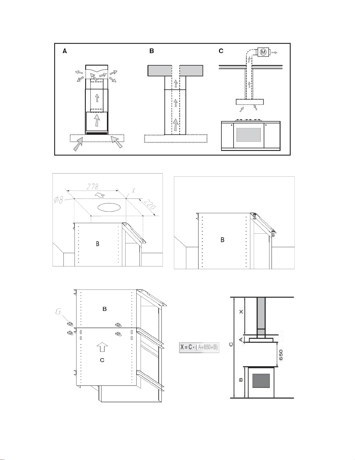
Fig.1
Fig.2 Fig.3
Fig.4 Fig.5
Page 3
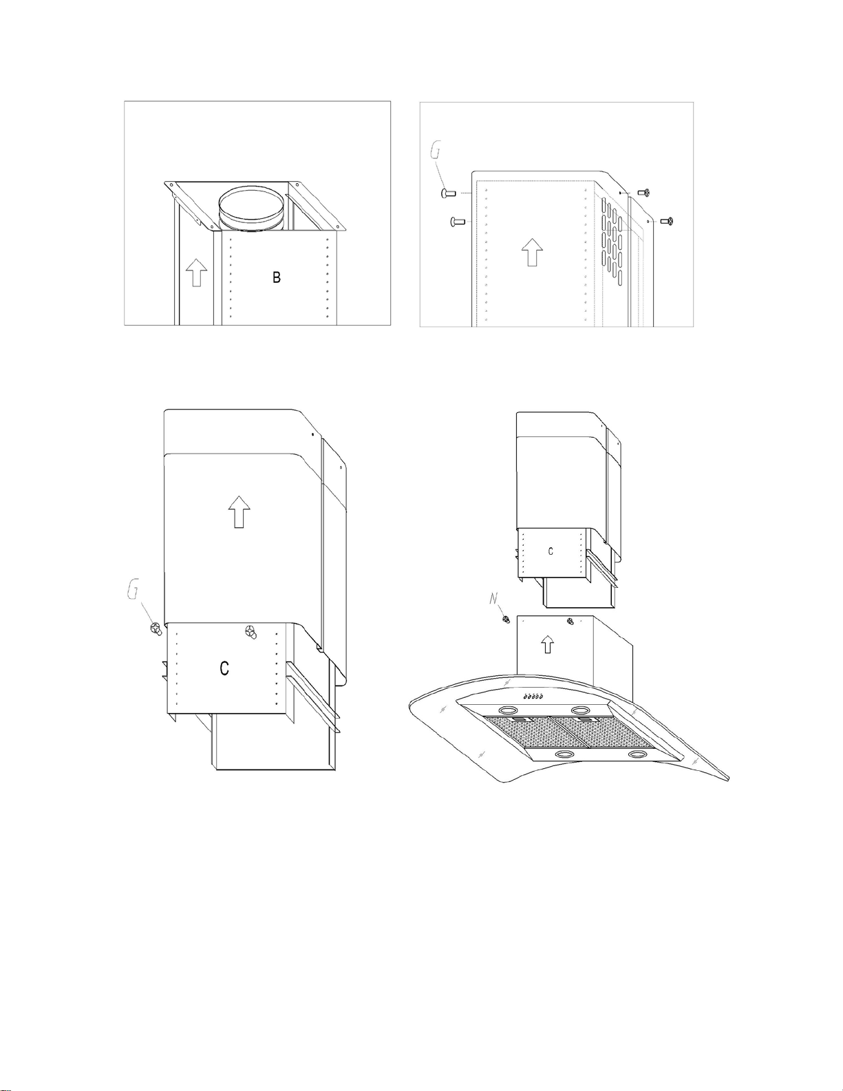
Fig.6 Fig.7
Fig.8 Fig.9
Page 4
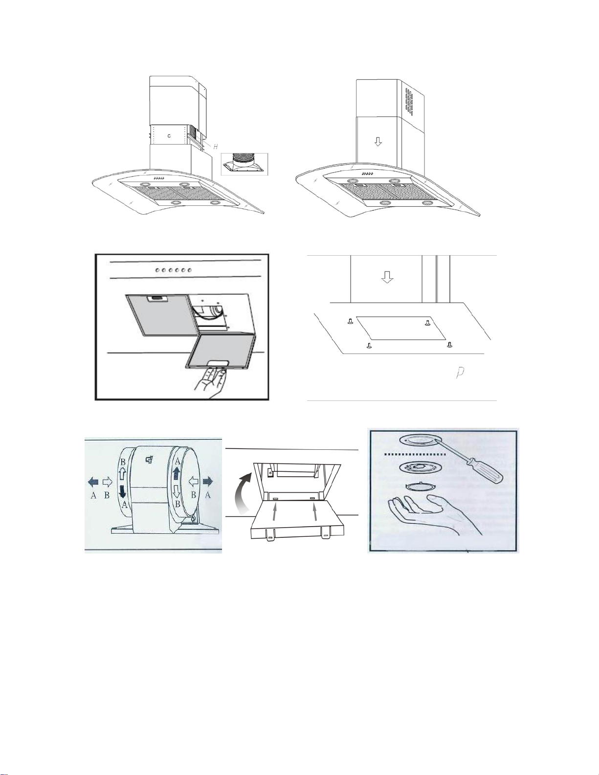
Fig.10 Fig.11
Fig.12 Fig.13
A B
Fig.14 Fig.15
Page 5
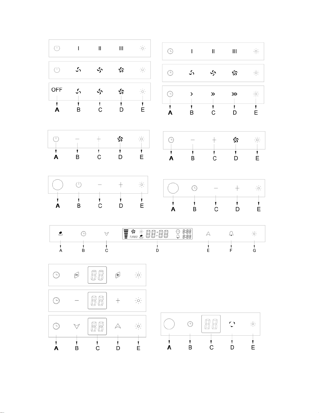
Fig.16 Fig.17
Fig.18 Fig.19
Fig.20 Fig.21
Fig.22
Fig.23 Fig.24
Page 6

Fig.25 Fig.26
GENERAL
Carefully read the following important information regarding installation
safety and maintenance. Keep this information booklet accessible for further
consultations.
The appliance has been designed for use in the ducting version (air exhaust
to the outside – Fig.1B), filtering version (air circulation on the inside –
Fig.1A) or with external motor (Fig.1C).
SAFETY PRECAUTION
1. Take care when the cooker hood is operating simultaneously with an
open fireplac e or burner that depend on the air in the environ men t a nd are
supplied by other than electrical energy, as the cooker hood removes the
air from the environment which a burner or fireplac e need for combustion.
The negative pressure in the environment must not exceed 4Pa (4x10⁻⁵
bar). Provide adequate ventilation in the environment for a safe operation
of the cooker hood.Follow the local laws applicable for external air
evacuation.
Before connecting the model to the electricity network:
- control the data plate (positioned inside the app liance) to ascertain that the
Page 7

voltage and power correspond to the network and the socket is suitable. If in
doubt ask a q ua lif ie d ele c tr ici an.
2. WARNING !
In certain c ircumstances electri cal appliances may be a danger hazar d.
A) Do not check the status of the filt ers while the cooker hood is operating
B) Do not touch bulbs or adjacent areas, during or straight after prolonged
use of the lighting in s tal la ti o n.
C) Flambè cooking is prohibited un derneath t he cooker hood
D) Avoid fre e flame, as it is damaging for the filters and a fire hazard
E) Constantly check food frying to avoid that the overheated oil may
become a fire hazard
F) Disconne ct the electrical plug prior to any maintenance.
G) This appliance is not intended for use by young children or infirm
persons without supervision
H) Young children should be supervised to ensure they do not play with the
appliance
I) There shall be adequate ventilation of the room when the range hood is
used at the sa me time as a ppliances burning gas or other fuels
J) There is a risk of fire if cleaning is not carried out in accordance with the
instructions
INSTALLATION INSTRUCTIONS
Assembly and electrical connections must be carried out by specialised
personnel.
• Electric Connection
Page 8

The appliance has been manufactured as a class I, therefore earth cable is
IEC227
North America
L=live
Brown
Black
N=neutral
Blue
White
E=earth
Green/Yellow
Green
necessary.
The connec tion to the mains is carried out as follows:
If not provided, connect a plug for the electrical load indicated on the
description label. Where a plug is provided,
the cooker hood must be installed in order that the plug is easily accessi ble.
An omnipolar switch with a minimum opening of 3mm
between contacts, in line with the electrical load and local standards, must be
placed between the appliance and the network in the case of direct
connection to the electri cal network.
• The minimum distance betwe en the support surfaces of the cooking pots on
the cooker top and the lowest part of the cooker hood must be at least 65 cm.
If a connect ion tube composed of two parts is used, the
upper part must be placed outside the lower part. Do not connect the cooker
hood exhaust to the same conductor used to circulate hot air or for
evacuating fumes from other appliances generated by other than an electrical
source. Before proceeding with the assembly operations, remove the
anti-grease filter(s) (Fig.12) so that the unit is easier to handle. In the case of
assembly of the appliance in the suction version prepare the hole for
evacuatio n of the air.
• Hood assembly
Remove the structure from the packaging and separate the upper part from
Page 9

the lower part.
- Please attention that the arrow is positioned on the same side as the
appliance controls. Make 4, Ø8 holes in the ceiling and drive in 3 screws
without completely tightening them(Fig2). Pay attention not to insert the
screw into the hole marked with an X on the hole template (the screws and
expansion p lugs must be suitable for the type of wall).
- Take the upper part of the structure B and insert the 3 slots onto the 3
screws that are not completely tightened. (Fig3)
Rotate slightly to fit.
Drive in the fourth screw X and tighten the remaining 3 to a llow definitive
blocking of the upp er part of str uc tur e B.
- Take the lower part of the telescopic structure C and insert it into the
upper struct ure B.
- Adjust the height (Fig.5) by referring to the amounts indicated in and
block it using the 8 unit screws G that a re supplied (Fig.4)
- Suction version: fix the flexible pipe to the prepared air evacuation hole
(Fig.6).
- Take the upper chimney piec e and fix it with 4 unit screw s G. (Fig.7)
- Take the lower chimney and fix it with 2 unit screws G, drive in hood to
avoid it down .(Fig.8)
- Insert the suction unit inside the structure and set in 4 mounting hole,
drive in 4 unit screw N (Fig. 9) .
- Fix the air evacuation pipe H (not supplied) onto the connection flange
(Fig.10)
- Unscrew the 2 screws G.and rest the lower chimney piece above the
cooker hood ( Fig.11).
Page 10

- If the cooker hood is supplied with a lower chimney piece that must be
fixed to the hood body with screws, remove the anti-grease filters from
the hood by acting on the relevant handles (Fig.12). T hen screw the lower
chimney piece pipe to the inside of the hood, using screws P(Fig.13).
Re-locate the filters in t heir seat.
USE AND MAINTENANCE
• It is recommended to operate the appliance prior to cooking.
It is recommended to leave the appliance in operation for 15 minutes after
cooking is terminated in order to completely eliminate cooking vapours and
odours.
The proper function of the cooker hood is conditioned by the regularity of
the mainten an ce oper ati o ns, in pa r tic u lar, the active carbon filter.
• The anti -grease filters capture the grease particles suspended in the air, and
are therefore subject to clogging according to the frequency of the use of the
appliance.
In order to prevent fire hazard, it is recommendable to clean the filter at a
maximum of 2 months by carrying out the following instructions:
- Remove the filters from the cooker hood and wash them in a solution of
water and neutra l li quid de te r gen t, leav i ng to soak.
- Rinse thoroughly with warm water and leave to dry.
- The filters may also be washed in the dishwas her.
The aluminum panels may alter in color after several washes. This is not
cause for cu stomer complaint nor r e pla cement of panels.
• The active carbon filters purify the air that is replaced in the environment.
The filters are not washable nor reuseable and must be replaced at maximum
Page 11

every four months. The saturation of the active carbon filter depends on the
•COMMANDS: (Fig.17)
E =LIGHT
frequency of use of the appliance, by the type of cooking and the reg ularity
of cleaning the antigrease filters. (Fig.14) To remove the charcoal filters
place on hand on one filter at a time and turn it toward the front part. The
charcoal filter can now be removed. Always ensure to replace both filters at
the same time .
• Clean the fan and other surfaces of the cooker hood regularly using a cloth
moistened with denatured alcohol or non abrasive liquid detergent.
• The illumination installation is designed for use during cooking and not for
prolonged general illumination of the environment. Prolonged use of the
illumination installation notably reduces the duration of the bulb. Use a
one-edged screwdriver or any other appropriate tool to lift and remove the
overhead light fixture. Replace the damaged lamp. Use only halogen lamps
as the original specification, avoiding contact with hands. Return the light
fixture to its position (snap fastening). (Fig. 15)
• COMMANDS: (Fig.16)
A = OFF
B = SPEED I / OFF
C = SPEED II / OFF
D = SPEED III / OFF
E = LIGHT
• If your appliance does not have the INTENSIVE speed function, press key
A for two seconds and it will be activated for 15 minutes after which it will
return to the previously set speed. When the function is active the LED
flashes.
By pressing any key for the exclusion of the hoo d light the hood wi ll return
immediately to its normal functioning.
The “automatic stop timer” delays stopping of the hood, which will
continue functioning for 15 minutes at the operating speed set at the
time this function is activated.
A= TIMER – 15 MINUTES
B= SPEED I
C= SPEED II
D= SPEED III
Page 12

FUNCTION KEYS: (Fig.18)
A == OFF
B == SPEED 1/“-”Control
C == SPEED 2/“+”Control
D == SPEED 4
E == LIGHT
By pressing key B、C or D individually, the speed for each key will be the
same as above table. At the same time indicated light will flash on the each
function key button. To stop the speed function pres s key A.
If Speed 3 is r equired,press key C adjust“+”. At Speed 3 program both key
B and key C in dication light will flash on each function key button.
To on the light press key E. To off the light press key E again.
FUNCTION KEYS: (Fig.19)
A == Automatic Stop T im er —15 minutes
B == Speed 1/“-”Control
C == Speed 2/“+”Control
D == Speed 4
E == Light
By pressing key B、C or D individually, the speed for each key will be the
same as above table. At the same time indicated light will flash on the each
function key butt ons. To stop the speed function press key A.
If Speed 3 is r equired,press key C adjust“+”. At Speed 3 program both key
B and key C in dication light will flash on each function key button.
To on the light press key E. To off the light press key E again.
When the appliance and light are ON together or separately, press key A the
Automatic Stop Timer will start the 15 minutes count down. Indication light
on the key A button will flash for the duration. To stop the Automatic Stop
Timer Function before 15 minutes time frame, pr ess key A again.
FUNCTION KEYS: (Fig.20, Fig.25)
A == Infrared Remote Control
B == Off
C == Speed 1/“-”Control
D == Speed 2/“+”Control
E == Light
By pressing key C or D individually, the speed for each key will be the same
as above table. At the same time indication light will flash on the each
Page 13

function key button. To stop the speed function pr ess key B.
If Speed 3 is r equired,press key D and adjust“+”. At Speed 3 program both
key C and key D indication light will flash on each function ke y button.
To on the light press key E. To off the light press key E again.
FUNCTION KEYS: (Fig.21, Fig.26)
A == Infrared Remote Control
B == Automatic Stop Timer —15minutes
C == Speed 1/“-”Control
D == Speed 2/“+”Control
E == Ligh
By pressing key C or D individually, the speed for each key will be the same
as above table. At the same time indicated light will flash on the each
function key buttons. To stop the speed function press key B. If using
Remote Control just press the“OFF”button
If Speed 3 is r equired,press key D and adjust“+”. At Speed 3 program both
key C and key D indication light will flash on each function key button. If
Speed 4 function is available, when Speed 4 function is ON key C and D
indication light will flash. If using Remote Control pre ss the “
”key.
To on the light press key E. To off the light press key E again.
When the appliance and light are ON together or separately, press key A the
Automatic Stop Timer will start the 15 minutes count down. Indication light
on the key A button will flash for the duration. To stop the Automatic Stop
Timer Function before 15 minutes time frame, press key A again.
•COMANDS PATTERN :( Fig.22)
A= Filterin g system / Set clock
B= Delay Timer
C= Speed 1/ “-” adjust / off
D= Digital display
E= Speed 1/ “+” adjust / off
F= Alarm
G= Light
When the Key A is flashing, at the same time “
”is flashing on the
digital display, it reminds the user to clean the filters. After it’s cleaned and
then assemble back, push the key A till the light is off to set the function
again.
When pushing key A for 3 seconds, the clock “
”on the digital
Page 14

display flashing, push key A to switch to set hours and minutes, and then
push C or E to s et the correct time. The Clock’s system is 24 hours.
When the motor is on, push the key B, the light is on, at the same time it
shows “
” is flashing as well on the digita l display,and to push
key B to switch hours and minutes, and it’s to set the time to
automatically shut off the motor by pushing key C or E. Push key B for 3
seconds to s top the delay timer.
Push key C or E, the first speed is on, and it shows “
display,and push key C once again to turn off;To run the 2
” o n the digital
nd
, 3rd and
“Turbo” speed, then push Key E. If it’s “Turbo”speed on, then push E
rd
once again to turn off; and to push key C down to 3
, 2nd and 1st
speed.
Push the key F, the light is flashing, and it shows“
” flashing on
the digital disp lay ,to push key F to switch hours and minutes,and to set
the alarm time by pushing the key C or E. To stop the alarm, push the
key F. And to cancel the alarm set, then push the key F for 3 sec onds.
Push the key G, the light is on, and it shows“
” on the digital display,
and push the G again to turn off the light.
•COMMANDS: (Fig.23)
A= Timer (a utomatic shut off)
B= Speed 1 / adjust / switch off
C= digital display screen (showi ng timer and speed)
D= Speed 3 / adjust / swi tch off
E= Light
When pushing A, digita l display sc reen shows "15 minutes" for timer, and
the minutes can be adj usted by pushing "+" or "-" on B and D. And the first
speed is on, pushin g A once to switch off, the digital disp lay shows "00".
When pushing B, it show s " F1" on the digital display screen, and the first
speed is on. Pushing B on ce to switch off, and the d igital display shows
"00".
When pushing D, it shows "F 3" on the d ig i tal di spl a y scree n, a nd the thir d
speed is on. Pushing D twice to swit ch off, and it shows "00" o n the scre en.
The second speed F2 and Turbo speed F4 can be adjusted by pushi ng B or
D.
When pushing E, the butt ons li g ht is on an d the light is on, only push E once
again to switch off th e lig ht.
Page 15

If the motor, light are working together , or only motor is working, pushing A,
Problem
Possible re ason
Solution
Hood doesn’ t work
No electric supply
Check the plug is connected
Check the main switch i s turned on
Poor airflow
Aluminum grease
filters clogged
Clean the filters and replace when
dry
Charcoal filters
clogged
Replace the charcoal filters
Motor running but no
air flow
Butterfly valve jammed
Contact techn ic ia n
Motor cuts after a
High temperature
safety devi ce activated
The kitchen is not sufficiently
ventilated
The hood is installed
The hood must be least 65cm from
automatic switch off timer is on, an d it will dela y 15 minutes to turn off the
motor and light. To push B or D to adju st the time, and to push A again to
stop the timer.
FUNCTION KEYS: (Fig.24, Fig.26)
A == Infrared Remote Control
B == Timer (Automatic Sh ut Off)
C == Digital Display(Timer/Speed)
D == Speed F1 /Cycle Control Adjustment/Off
E == Light
When key B is pressed, digital display screen will display 15 minutes. For
cycle control adjustment and Speed F1 press key D. To stop the operation
press key B again the digital display screen will show 00. If using remote
control pre ss “OFF” button.
When key D is being pressed, the digital display screen will show F1 and
speed 1 will ON. To stop F1 function press key D until the digital display
screen shown 00.
The F2, F3 Or F4 (Turbo) function can be adj ust e d thr u key D.
For ON/OFF l ight press key E.
When the appliance and light are ON together or separately, press key B the
Automatic Stop Timer will start the 15 minutes count down. Key D can also
be used to extend the time of Automatic Stop Timer. To stop the Automatic
Stop Timer Function before 15 minutes time frame, pr ess key B again.
Troubleshooting
few minutes
Page 16

too near the cooking
stove
stove
Strong cooking smell
Charcoal filters not
installed
In re-circulating mode, charcoal
filters must be installe d
Oil dripping onto
stove
Oil cup missing or not
Remove aluminum filter and
Aluminum grease filter
saturated
Wash the aluminum grease filters
Whirring sou nd
Something in contact
with fan blade
Contact with te c hnician
installed
replace oil cup
THE MANUFACTURORY DECLINES ALL RESPONSIBILITY FOR
EVENTUAL DAMAGES CAUSED BY BREACHING THE ABOVE
WARNINGS.
 Loading...