

Page 1

Revision: 01/2021
Copyright© 2014 – 2021
Campbell Scientific, Inc.
Page 2

Table of contents
1. Introduction 1
2. Precautions 1
3. Initial inspection 2
4. QuickStart 2
5. Overview 5
6. Specifications 5
6.1 Wind direction 6
6.2 Wind speed 6
7. Installation 6
7.1 WindSonic4 wiring 6
7.2 Data logger programming 7
7.2.1 Programming 8
7.3 Siting 9
7.4 Mount the sensor 9
8. Operation 10
8.1 Sensor configuration 10
8.2 SDI-12 measurement details 11
8.3 Long cables 11
9. Maintenance and troubleshooting 12
9.1 Troubleshooting 12
9.2 Maintenance 12
10. Siting references 13
Appendix A. Importing Short Cut code into CRBasic Editor 14
Appendix B. Determining True North and sensor orientation 15
B.1 Online magnetic declination calculator 17
Appendix C. SDI-12 sensor support 19
C.1 SDI-12 command basics 19
Table of Contents - i
Page 3

C.1.1 Acknowledge active command (a!) 20
C.1.2 Send identification command (al!) 20
C.1.3 Start verification command (aV!) 21
C.1.4 Address query command (?!) 21
C.1.5 Change address command (aAb!) 21
C.1.6 Start measurement commands (aM!) 22
C.1.7 Start concurrent measurement commands (aC!) 22
C.1.8 Start measurement commands with cyclic redundancy check (aMC! and aCC!) 24
C.1.9 Stopping a measurement command 24
C.1.10 Send data command (aD0! … aD9!) 24
C.1.11 Continuous measurement command (aR0! … aR9!) 25
C.2 SDI-12 transparent mode 25
C.2.1 Changing an SDI-12 address 26
Table of Contents - ii
Page 4
1. Introduction
The WindSonic4 is a two-dimensional ultrasonic anemometer for measuring wind speed and
wind direction. It provides an alternative to traditional mechanical cup and vane or propeller and
vane anemometers. Unlike mechanical anemometers, the WindSonic4 has no moving parts that
need to be periodically replaced—minimizing routine maintenance costs.
The WindSonic4 outputs an SDI-12 signal.
NOTE:
This manual provides information only for CRBasic data loggers. For retired Edlog data logger
support, see an older manual at www.campbellsci.com/old-manuals.
2. Precautions
l READ AND UNDERSTAND the Safety section at the back of this manual.
l The WindSonic4 is not recommended for conditions where rime, ice, or horizontal snow
will occur. It is not heated.
l The WindSonic4 is a precision instrument. Please handle it with care.
l If the WindSonic4 is to be installed at heights over 2 m (6 ft), be familiar with tower safety
and follow safe tower climbing procedures.
l DANGER—Use extreme care when working near overhead electrical wires. Check for
overhead wires before mounting the WindSonic4 or before raising a tower.
l The black outer jacket of the cable is Santoprene® rubber. This compound was chosen for
its resistance to temperature extremes, moisture, and UV degradation. However, this jacket
will support combustion in air. It is rated as slow burning when tested according to U.L. 94
H.B. and will pass FMVSS302. Local fire codes may preclude its use inside buildings.
WindSonic4 Two-Dimensional Sonic Anemometer 1
Page 5

3. Initial inspection
l Upon receipt of the WindSonic4, inspect the packaging and contents for damage. File
damage claims with the shipping company. Immediately check package contents against
the shipping documentation. Contact Campbell Scientific about any discrepancies.
l The model number and cable length are printed on a label at the connection end of the
cable. Check this information against the shipping documents to ensure the expected
product and cable length are received.
4. QuickStart
A video that describes data logger programming using Short Cut is available at:
www.campbellsci.com/videos/cr1000x-data logger-getting-started-program-part-3 . Short Cut
is an easy way to program your data logger to measure the sensor and assign data logger wiring
terminals. Short Cut is available as a download on www.campbellsci.com. It is included in
installations of LoggerNet, RTDAQ, and PC400.
The following procedure also shows using Short Cut to program the WindSonic4.
1. Open Short Cut and click Create New Program.
2. Double-click the data logger model.
WindSonic4 Two-Dimensional Sonic Anemometer 2
Page 6
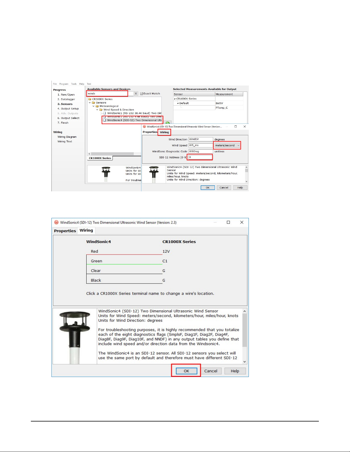
3. In the Available Sensors and Devices box, type WindSonic1 or locate the sensor in the
Sensors > Meteorological > Wind Speed & Direction folder. Double-click the WindSonic4
(SDI-12) Two Dimensional Ultrasonic Wind Sensor. The wind speed defaults to meters per
second. This can be changed by clicking the Wind Speed box and selecting one of the
other options. Type the correct SDI-12 Address; default is 0.
4. Click the Wiring tab to see how the sensor is to be wired to the data logger. Click OK after
wiring the sensor.
5. Repeat steps 3 and 4 for other sensors.
WindSonic4 Two-Dimensional Sonic Anemometer 3
Page 7
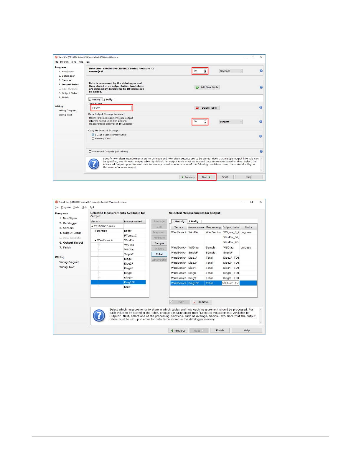
6. In Output Setup, type the scan rate, meaningful table names, and Data Output Storage
Interval. Click Next.
7. Select the measurement and its associated output option.
8. Click Finish and save the program. Send the program to the data logger if the data logger
is connected to the computer.
9. If the sensor is connected to the data logger, check the output of the sensor in data display
in LoggerNet, RTDAQ, PC400, or PC200W to make sure it is making reasonable
measurements.
WindSonic4 Two-Dimensional Sonic Anemometer 4
Page 8

5. Overview
The WindSonic4 is manufactured by Gill Instruments, Ltd. It is an ultrasonic anemometer for
measuring wind direction and wind speed. Two pairs of orthogonally oriented transducers sense
horizontal wind. The transducers bounce the ultrasonic signal from a hood, minimizing the
effects of transducer shadowing and flow distortion.
The WindSonic4 outputs data using the SDI-12 interface, which is compatible with all
contemporary data loggers as well as the CR200(X)-series and CR5000. SDI-12 is a three-wire
digital interface standard used by processor-based sensors and digital recording devices.
The WindSonic4 includes a user-specified cable to interface to a Campbell Scientific data logger.
A serial cable (WINDSONICRCBL-L) is available for interfacing a WindSonic4 to a computer
running the manufacturer’s computer support software. The cable and software are used during
troubleshooting. A copy of this computer support software is available at
www.gill.co.uk/main/software.html. WindView is used for WindSonic4 anemometers with serial
numbers of 0810001 or greater, and WindCom is used for WindSonic4 anemometers with serial
numbers that are less than 0810001.
Features:
l Low maintenance—no moving parts significantly reduces maintenance cost and time
l Minimum detectable wind speed of 0.01meters per second
l Compatible with Campbell Scientific CRBasic data loggers: CR6, CR3000, CR1000X, CR800
series, CR300 series, CR1000, CR200(X) series, and CR5000
6. Specifications
Output signal:
Output variables:
Measurement frequency:
Current drain:
Operating temperature:
SDI-12 version 1.3; address factory set to 0
wind direction, wind speed, and diagnostic or ux, uy, and
diagnostic
40Hz block averaged to a programmable output frequency,
factory set to 1Hz
<12 mA @ 12 V
–35 to 70 °C
WindSonic4 Two-Dimensional Sonic Anemometer 5
Page 9

Storage temperature:
–40 to 80 °C
Dimensions:
Weight:
Operating humidity:
142 x 160 mm (5.6 x 6.3 in)
500 g (1.1 lb)
<5% to 100% RH
6.1 Wind direction
Operating range:
Accuracy:
Output resolution:
0 to 359° (no dead band)
±3°
1°
6.2 Wind speed
Operating range:
Accuracy:
Output resolution:
0 to 60 m/s
±2% @ 12 m/s
0.01 m/s
7. Installation
If you are programming your data logger with Short Cut, skip WindSonic4 wiring (p. 6) and Data
logger programming (p. 7). Short Cut does this work for you. See QuickStart (p. 2) for a Short Cut
tutorial.
7.1 WindSonic4 wiring
The WindSonic4 interfaces to a Campbell Scientific data logger using SDI-12 (Table 7-1 (p. 7)).
WindSonic4 Two-Dimensional Sonic Anemometer 6
Page 10
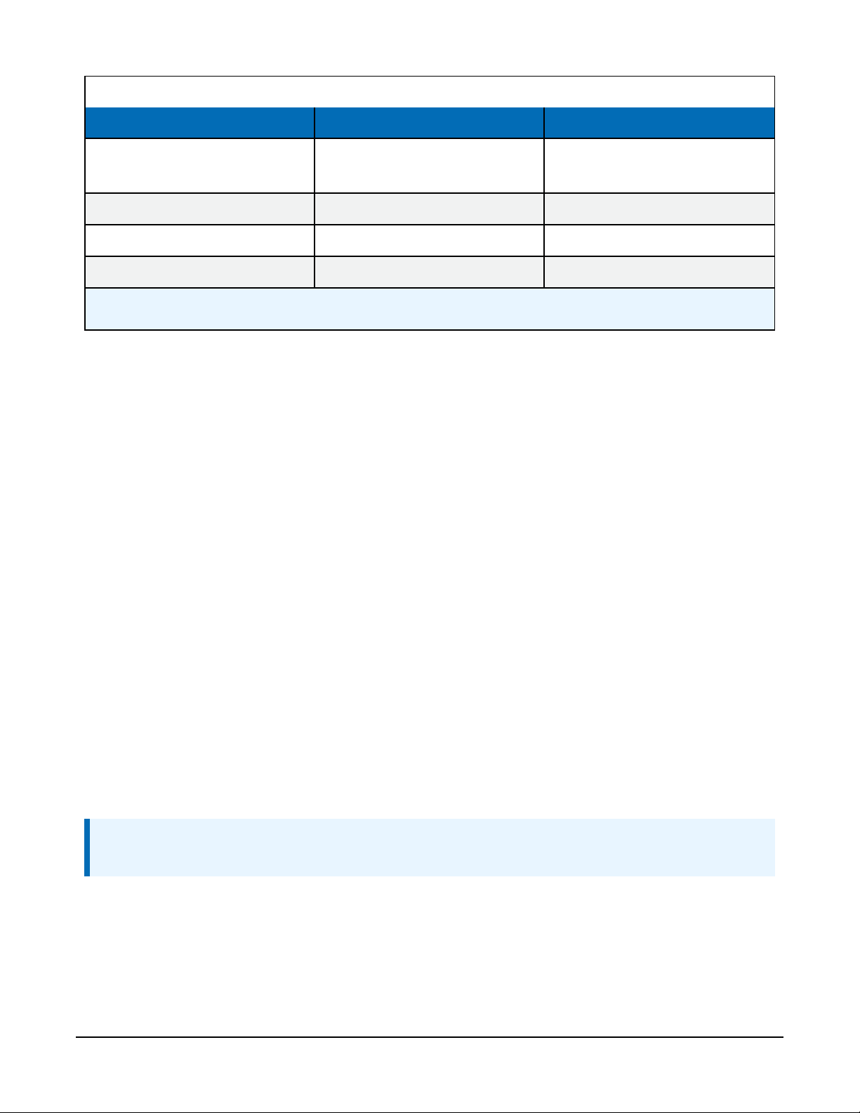
Table 7-1: WindSonic4 to data logger connections
Description Color Data logger
SDI-12 Data Green
SDI-12 Power Red 12V
SDI-12 Reference Black G
Shield Clear ⏚ (analog ground)
1
U and C terminals are automatically configured by the measurement instruction for Campbell Scientific CR6 data
logger.
To use more than one sensor per data logger, either connect the different sensors to different
terminals on the data logger or change the SDI-12 addresses of the sensors and wire them to the
same terminal. Each SDI-12 sensor connected to the same terminal must have a unique SDI-12
address. The factory-set address for the WindSonic4 is 0. Possible addresses are a number from 0
to 9. Using unique SDI-12 addresses reduces the use of terminals on the data logger and allows
sensors to be connected in a daisy-chain fashion that can minimize cable runs in some
applications. At a 1Hz measurement rate, a maximum of four WindSonic4s can be measured by a
data logger.
For the CR6 and CR1000X, triggering conflicts may occur when a companion terminal is used for
a triggering instruction such as TimerInput(), PulseCount(), or WaitDigTrig(). For
example, if the WindSonic4 is connected to C3 on a CR1000X, C4 cannot be used in the
TimerInput(), PulseCount(), or WaitDigTrig() instructions.
U configured for SDI-12
C, SDI-12,
1
7.2 Data logger programming
Short Cut is the best source for up-to-date programming code for Campbell Scientific data
loggers. If your data acquisition requirements are simple, you can probably create and maintain a
data logger program exclusively with Short Cut. If your data acquisition needs are more complex,
the files that Short Cut creates are a great source for programming code to start a new program
or add to an existing custom program.
NOTE:
Short Cut cannot edit programs after they are imported and edited in CRBasic Editor.
A Short Cut tutorial is available in QuickStart (p. 2). If you wish to import Short Cut code into
CRBasic Editor to create or add to a customized program, follow the procedure in Importing
Short Cut code into CRBasic Editor (p. 14). Programming basics for CRBasic data loggers are
WindSonic4 Two-Dimensional Sonic Anemometer 7
Page 11
provided in the following section. Downloadable example programs are available at
www.campbellsci.com/downloads/windsonic4-program-examples.
7.2.1 Programming
The WindSonic4 updates the SDI-12 output at a frequency of 1 Hz. The SDI12Recorder()
CRBasic instruction programs the data loggers to measure the WindSonic4. This instruction sends
a request to the sensor to make a measurement and then retrieves the measurement from the
sensor. For the most data loggers, the SDI12Recorder() instruction has the following syntax:
SDI12Recorder(Destination, SDIPort, SDIAddress, “SDICommand”, Multiplier,
Offset, FillNAN, WaitonTimeout)
For the SDIAddress, alphabetical characters need to be enclosed in quotes (for example, “A”).
Also enclose the SDICommand in quotes as shown. The most appropriate SDI-12 command to
retrieve data from the WindSonic4 is the Ro!, where o is the data format option (Table 7-2 (p.
8)). When using the "Ro!" command, the Destination parameter needs to be a variable
array with three elements.
FillNAN and WaitonTimeout are optional parameters (refer to CRBasic Help for more
information).
When using a CR200(X)-series data logger, the SDI12Recorder() instruction has the
following syntax:
SDI12Recorder(Destination,"OutString",Multiplier,Offset)
OutString consists of the SDI-12 address and command. Enclose the OutString in quotes
as shown.
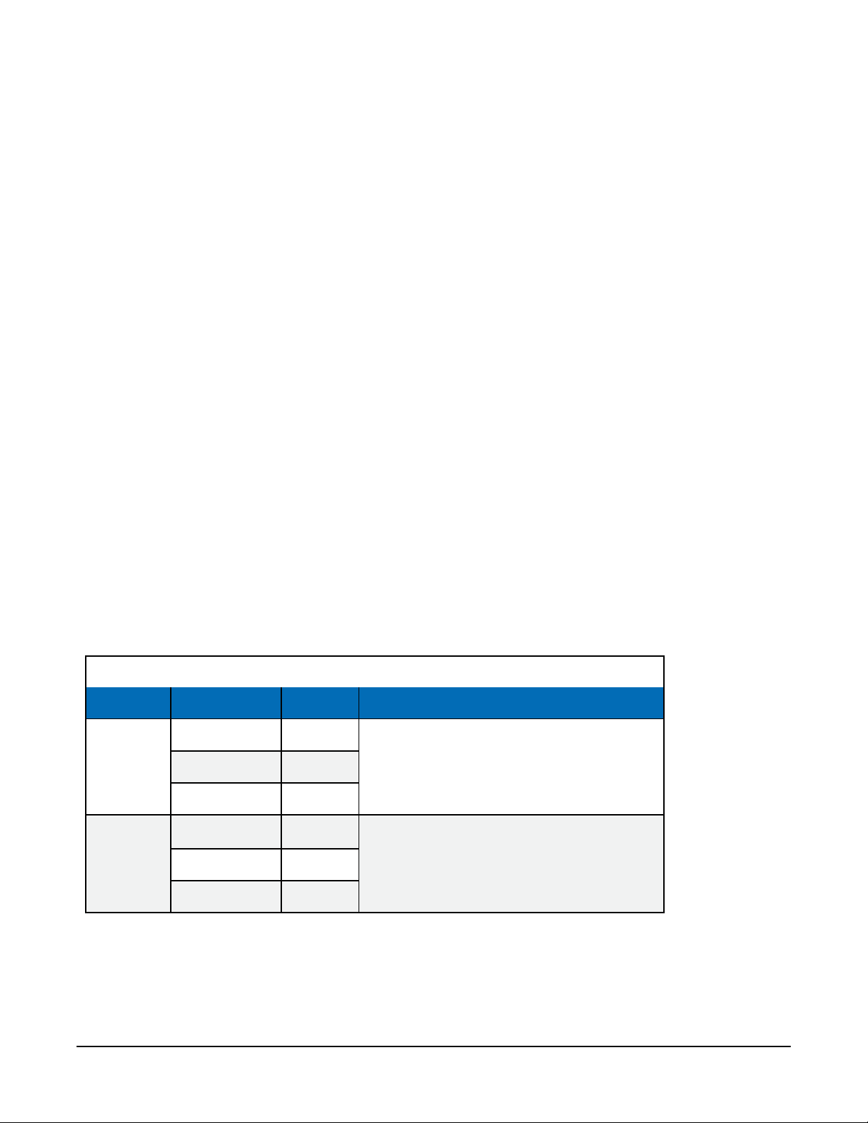
Table 7-2: WindSonic4 data format option
Option (o) Output Units Comment
wind direction degrees
0
status unitless
uxwind
1
uywind m/s
status unitless
m/s
Compass polar coordinate systemwind speed m/s
Orthogonal right hand coordinate system
WindSonic4 Two-Dimensional Sonic Anemometer 8
Page 12

NOTE:
To support the Ro! command, a CR200(X)-series or CR5000 data logger need a current
operating system. The most current data logger operating systems are available on the
Campbell Scientific website at: www.campbellsci.com/downloads.
See SDI-12 measurement details (p. 11) for more information about this instruction.
7.3 Siting
Locate the WindSonic4 away from obstructions such as trees and buildings. The distance
between wind sensors and the nearest obstruction should be ten times the height of the
obstruction. If it is necessary to mount the WindSonic4 on the roof of a building, the height of
the sensor, above the roofline, should be at least 1.5 times the height of the building. See Siting
references (p. 13) for a list of references that discuss siting wind direction and speed sensors.
7.4 Mount the sensor
Mount the WindSonic4 using the WindSonic Mounting Pipe Kit, which consists of an aluminum
mounting tube, three pan truss screws, CM220 Right Angle Mounting bracket, two U-bolts, and
four nuts.
1. Thread the connector end of the cable through the mounting tube; start at the end without
the three threaded holes.
2. Attach the female mating connector on the cable to the male mating connector located on
the bottom of the WindSonic4.
3. Secure the WindSonic4 to the mounting tube using the three pan-head screws.
4. Attach the mounting tube to a crossarm using the the CM220 Right Angle Mounting
bracket, U-bolts, and nuts (see FIGURE 7-1 (p. 10)).
5. Mount the crossarm to the tripod or tower.
6. Orient the WindSonic4 so that the colored North marker arrows point to True North (see
FIGURE 7-1 (p. 10)). See Determining True North and sensor orientation (p. 15) for more
information.
WindSonic4 Two-Dimensional Sonic Anemometer 9
Page 13

FIGURE 7-1. WindSonic4 mounted on a crossarm
7. Route the sensor cable along the underside of the crossarm to the tripod or tower, and to
the instrument enclosure.
8. Secure the cable to the crossarm and tripod or tower using cable ties.
8. Operation
This section discusses the following:
8.1 Sensor configuration 10
8.2 SDI-12 measurement details 11
8.3 Long cables 11
8.1 Sensor configuration
To mimic a mechanical anemometer, the WindSonic4 output frequency must match the data
logger scan frequency. The factory setting for the WindSonic4 is 1 Hz, which is 1 output per
second. The data output frequency of the WindSonic4 cannot be changed.
WindSonic4 Two-Dimensional Sonic Anemometer 10
Page 14

8.2 SDI-12 measurement details
The WindSonic4 typically uses an R0! or R1! command. When the data logger issues an R0! or
R1! command, the WindSonic4 immediately begins transmitting the most current wind
measurements to the data logger. After receiving the R0! or R1! command, it takes the
WindSonic4 approximately 190 milliseconds ±10 milliseconds to transmit the data.
The WindSonic4 can also use an M0! or M1! command. When using an M0! or M1! command,
the data logger waits for the time specified by the sensor, sends the D! command, pauses its
operation, and waits until either it receives the data from the sensor or the sensor timeout
expires. If the data logger receives no response, it will send the command a total of three times,
with three retries for each attempt, or until a response is received. The M0! or M1! command will
take slightly longer to retrieve the data because of the additional handshaking required. For all
practical purposes, a data logger can measure up to four WindSonic4s at 1 Hz.
The WindSonic4 also supports the R0C!, R1C!, M0C!, and MC! commands, which are the same
as the R! and M! commands, but a cyclic redundancy check (CRC) is performed that validates
the data. Use of the checksum option is only necessary for long cable runs.
NOTE:
This section briefly describes using the SDI-12 commands. For additional SDI-12 information,
refer to SDI-12 sensor support (p. 19). A complete list of SDI-12 commands supported by the
WindSonic4 is available in the Gill WindSonic manual at
www.gill.co.uk/products/anemometer/windsonic.htm.
8.3 Long cables
Although the SDI-12 standard specifies the maximum total cable length to be 61 m (200 ft), the
WindSonic4 can have cable lengths up to 90 m (300 ft). Digital data transfer eliminates offset
errors due to cable lengths. However, digital communications can break down when cables are
too long, resulting in either no response from the sensor or corrupted readings.
WindSonic4 Two-Dimensional Sonic Anemometer 11
Page 15

9. Maintenance and troubleshooting
NOTE:
All factory repairs and recalibrations require a returned material authorization (RMA) and
completion of the “Statement of Product Cleanliness and Decontamination” form. Refer to
the Assistance page at the end of this manual for more information.
9.1 Troubleshooting
The WindSonic4 outputs a status code (Table 9-1 (p. 12)) along with each wind direction and
speed measurement. The data logger program can filter out data when the status code is not 00.
If the WindSonic4 is not powered, not connected, is using the wrong COM port/SDI-12 address,
or has missed a sample, the wind direction and speed measurement will be NaN. The program
can filter out these values and report the number of good samples that were used in computing
the online statistics. If the total number of good samples is less than 98% of the expected
samples, send the WindSonic4 to the factory for repair (see Assistance).
Table 9-1: Status codes
Code Status Comment
00 Okay All okay
01 Axis 1 failed Insufficient samples, possible path obstruction
02 Axis 2 failed Insufficient samples, possible path obstruction
04 Both axes failed Insufficient samples, possible path obstruction
08 NVM error Nonvolatile Memory checksum failed
09 ROM error Read Only Memory checksum failed
10 Maximum gain Questionable wind measurements
9.2 Maintenance
There are no user-serviceable parts on the WindSonic4. Keep the transducer paths clear of any
obstructions.
WindSonic4 Two-Dimensional Sonic Anemometer 12
Page 16

CAUTION:
When clearing the transducer paths, do not remove or damage the rubber caps on the
transducers.
Use a cloth and mild detergent to gently clean the transducers.
CAUTION:
Do not use solvents and avoid scratching or damaging the rubber caps.
If the WindSonic4 is damaged, fails to output data, or sends a nonzero status number (Table 9-1
(p. 12)), return it to Campbell Scientific for repair (see Assistance).
10. Siting references
The following references give detailed information on siting wind direction and wind speed
sensors.
EPA, 1987: On-Site Meteorological Program Guidance for Regulatory Modeling Applications,
EPA-450/4-87-013, Office of Air Quality Planning and Standards, Research Triangle Park, NC,
27711.
EPA, 1989: Quality Assurance Handbook for Air Pollution Measurements System, Office of
Research and Development, Research Triangle Park, NC, 27711.
The State Climatologist, 1985: Publication of the American Association of State Climatologists:
Height and Exposure Standards, for Sensors on Automated Weather Stations, vol. 9, No. 4.
WMO, 1983: Guide to Meteorological Instruments and Methods of Observation, World
Meteorological Organization, No. 8, 5th edition, Geneva, Switzerland.
WindSonic4 Two-Dimensional Sonic Anemometer 13
Page 17

Appendix A. Importing Short
Cut code into CRBasic Editor
Short Cut creates a .DEF file that contains wiring information and a program file that can be
imported into the CRBasic Editor. By default, these files reside in the C:\campbellsci\SCWin
folder.
Import Short Cut program file and wiring information into CRBasic Editor:
1. Create the Short Cut program. After saving the Short Cut program, click the Advanced tab
then the CRBasic Editor button. A program file with a generic name will open in CRBasic.
Provide a meaningful name and save the CRBasic program. This program can now be
edited for additional refinement.
NOTE:
Once the file is edited with CRBasic Editor, Short Cut can no longer be used to edit the
program it created.
2. To add the Short Cut wiring information into the new CRBasic program, open the .DEF file
located in the C:\campbellsci\SCWin folder, and copy the wiring information, which is at
the beginning of the .DEF file.
3. Go into the CRBasic program and paste the wiring information into it.
4. In the CRBasic program, highlight the wiring information, right-click, and select Comment
Block. This adds an apostrophe (') to the beginning of each of the highlighted lines, which
instructs the data logger compiler to ignore those lines when compiling. The Comment
Block feature is demonstrated at about 5:10 in the CRBasic | Features video .
WindSonic4 Two-Dimensional Sonic Anemometer 14
Page 18

Appendix B. Determining True North and sensor orientation
The orientation of the WindSonic4 north arrow markers is found by reading a magnetic compass
and applying the site-specific correction for magnetic declination; where the magnetic
declination is the number of degrees between true north and magnetic north. Obtain the
magnetic declination for a specific site from a USGS map, local airport, or through a NOAA web
calculator (Online magnetic declination calculator (p. 17)). A general map showing magnetic
declination for the Conterminous United States is shown in FIGURE B-1 (p. 15).
FIGURE B-1. Magnetic declination for the conterminous United States (2015)
Declination angles east of True North are considered negative, and are subtracted from 360
degrees to get True North as shown FIGURE B-2 (p. 16) (0° and 360° are the same point on a
compass). Declination angles west of True North are considered positive, and are added to 0
degrees to get True North as shown in FIGURE B-3 (p. 16).
WindSonic4 Two-Dimensional Sonic Anemometer 15
Page 19

For example, the declination for Longmont, CO (10 June 2006) is 9.67°, thus True North is 360° –
9.67°, or 350.33° as read on a compass. Likewise, the declination for McHenry, IL (10 June 2006) is
–2.68°, and True North is 0° – (–2.68°), or 2.68° as read on a compass.
FIGURE B-2. A declination angle east of True North (positive) is subtracted from
360 (0) degrees to find True North
FIGURE B-3. A declination angle west of True North (negative) is subtracted from
0 (360) degrees to find True North
WindSonic4 Two-Dimensional Sonic Anemometer 16
Page 20

B.1 Online magnetic declination calculator
The magnetic declination web calculator published by NOAA’s Geophysical Data Center is
available at www.ngdc.noaa.gov/geomag-web. This web page calculates declination based on
the latitude and longitude. You can look up your site’s latitude and longitude by entering the
Zip Code or the Country and City, and then clicking the Get & Add Lat/Lon button (FIGURE B-4
(p. 17)). Click the Calculate button to get the magnetic declination.
FIGURE B-4. NOAA web calculator
FIGURE B-5 (p. 18) shows that the calculated declination for Logan, UT is 11.78 degrees (11 August
2015). The declination for Utah is positive (east of north), so True North for this site is 360 – 11.78,
or 348.22 degrees. The annual change is 6 minutes west per year.
WindSonic4 Two-Dimensional Sonic Anemometer 17
Page 21

FIGURE B-5. NOAA calculated declination using HTML result format
WindSonic4 Two-Dimensional Sonic Anemometer 18
Page 22

Appendix C. SDI-12 sensor support
SDI-12, Serial Data Interface at 1200 baud, is a protocol developed to simplify sensor and data
logger compatibility. Only three wires are necessary — serial data, ground, and 12 V. With unique
addresses, multiple SDI-12 sensors can connect to a single SDI-12 terminal on a Campbell
Scientific data logger.
This appendix discusses the structure of SDI-12 commands and the process of querying SDI-12
sensors. For more detailed information, refer to version 1.4 of the SDI-12 protocol, available at
www.sdi-12.org.
For additional information, refer to the SDI-12 Sensors | Transparent Mode and SDI-12 Sensors |
Watch or Sniffer Mode videos.
C.1 SDI-12 command basics
SDI-12 commands have three components:
l Sensor address (a) – a single character and the first character of the command. Use the
default address of zero (0) unless multiple sensors are connected to the same port.
l Command body – an upper case letter (the “command”), optionally followed by one or
more alphanumeric qualifiers.
l Command termination (!) – an exclamation mark.
An active sensor responds to each command. Responses have several standard forms and always
terminate with <CR><LF> (carriage return and line feed). Standard SDI-12 commands are listed
in Table C-1 (p. 19).
Table C-1: Campbell Scientific sensor SDI-12 command and response set
Name Command
Acknowledge Active
Send Identification
Start Verification
Address Query
a!
aI!
aV!
?!
Response
a<CR><LF>
allccccccccmmmmmmvvvxxx...xx
<CR><LF>
atttn <CR><LF>
a<CR><LF>
1
WindSonic4 Two-Dimensional Sonic Anemometer 19
Page 23

Table C-1: Campbell Scientific sensor SDI-12 command and response set
Name Command
Change Address
Start Measurement
Start Measurement
and Request CRC
Start Concurrent Measurement
StartConcurrentMeasurement
and Request CRC
Send Data
Continuous Measurement
Continuous Measurement
and Request CRC
aAb!
aM!
aM1!...aM9!
aMC!
aMC1!...aMC9!
aC!
aC1!...aC9!
aCC!
aCC1!...aCC9!
aD0!...aD9!
aR0!...aR9!
aRC0!...aRC9!
Response
b<CR><LF>
atttn<CR><LF>
atttn <CR><LF>
atttnn<CR><LF>
atttnn<CR><LF>
a<values><CR><LF> or
a<values><CRC><CR><LF>
a<values><CR><LF>
a<values><CRC><CR><LF>
1
Extended Commands
1
Information on each of these commands is given in the following sections.
aXNNN!
a<values><CR><LF>
C.1.1 Acknowledge active command (a!)
The Acknowledge Active command (a!) is used to test a sensor on the SDI-12 bus. An active
sensor responds with its address.
C.1.2 Send identification command (al!)
Sensor identifiers are requested by issuing command aI!. The reply is defined by the sensor
manufacturer but usually includes the sensor address, SDI-12 version, manufacturer’s name, and
sensor model information. Serial number or other sensor specific information may also be
included.
aI!
a Sensor SDI-12 address
ll SDI-12 version number (indicates compatibility)
allccccccccmmmmmmvvvxxx...xx<CR><LF>
cccccccc 8-character vendor identification
WindSonic4 Two-Dimensional Sonic Anemometer 20
Page 24

mmmmmm 6 characters specifying the sensor model
vvv 3 characters specifying the sensor version (operating system)
xxx…xx
<CR><LF>
Source: SDI-12: A Serial-Digital Interface Standard for Microprocessor-Based Sensors (see References).
Up to 13 optional characters used for a serial number or other specific
sensor information that is not relevant for operation of the data logger
Terminates the response
C.1.3 Start verification command (aV!)
The response to a Start Verification command can include hardware diagnostics, but like the aI!
command, the response is not standardized.
Command: aV!
Response: atttn<CR><LF>
a = sensor address
ttt = time, in seconds, until verification information is available
n = the number of values to be returned when one or more subsequent D! commands are issued
C.1.4 Address query command (?!)
Command ?! requests the address of the connected sensor. The sensor replies to the query with
the address, a. This command should only be used with one sensor on the SDI-12 bus at a time.
C.1.5 Change address command (aAb!)
Multiple SDI-12 sensors can connect to a single SDI-12 terminal on a data logger. Each device on
a single terminal must have a unique address.
A sensor address is changed with command aAb!, where a is the current address and b is the
new address. For example, to change an address from 0 to 2, the command is 0A2!. The sensor
responds with the new address b, which in this case is 2.
NOTE:
Only one sensor should be connected to a particular terminal at a time when changing
addresses.
WindSonic4 Two-Dimensional Sonic Anemometer 21
Page 25

C.1.6 Start measurement commands (aM!)
A measurement is initiated with the M! command. The response to each command has the form
atttn<CR><LF>, where
a = sensor address
ttt = time, in seconds, until measurement data is available. When the data is ready, the sensor
notifies the data logger, and the data logger begins issuing D commands.
n = the number of values returned when one or more subsequent D commands are issued. For
the aM! command, n is an integer from 0 to 9.
When the aM! is issued, the data logger pauses its operation and waits until either it receives the
data from the sensor or the time, ttt, expires. Depending on the scan interval of the data logger
program and the response time of the sensor, this may cause skipped scans to occur. In this case
make sure your scan interval is longer than the longest measurement time (ttt).
Table C-2: Example aM! sequence
0M!
00352<CR><LF>
0<CR><LF>
0D0!
0+.859+3.54<CR><LF>
The data logger makes a request to sensor 0 to start a measurement.
Sensor 0 immediately indicates that it will return two values within
the next 35 seconds.
Within 35 seconds, sensor 0 indicates that it has completed the
measurement by sending a service request to the data logger.
The data logger immediately issues the first D command to collect
data from the sensor.
The sensor immediately responds with the sensor address and the two
values.
C.1.7 Start concurrent measurement commands (aC!)
A concurrent measurement (aC!) command follows the same pattern as the aM! command with
the exception that it does not require the data logger to pause its operation, and other SDI-12
sensors may take measurements at the same time. The sensor will not issue a service request to
notify the data logger that the measurement is complete. The data logger will issue the aD0!
command during the next scan after the measurement time reported by the sensor has expired.
To use this command, the scan interval should be 10 seconds or less. The response to each
command has the form atttn<CR><LF>, where
a = the sensor address
ttt = time, in seconds, until the measurement data is available
WindSonic4 Two-Dimensional Sonic Anemometer 22
Page 26

nn = the number of values to be returned when one or more subsequent D commands are
issued.
See the following example. A data logger has three sensors wired into terminal C1. The sensors
are addresses X, Y, and Z. The data logger will issue the following commands and receive the
following responses:
Table C-3: Example aC! sequence
XC!
X03005<CR><LF>
YC!
Y04006<CR><LF>
ZC!
Z02010<CR><LF>
ZD0!
The data logger makes a request to sensor X to start
a concurrent measurement.
Sensor X immediately indicates that it will have 5
(05) values ready for collection within the next 30
(030) seconds.
The data logger makes a request to sensor Y to start
a concurrent measurement.
Sensor Y immediately indicates that it will have 6
(06) values ready for collection within the next 40
(040) seconds.
The data logger makes a request to sensor Z to start
a concurrent measurement.
Sensor Z immediately indicates that it will have 10
values ready for collection within the next 20 (020)
seconds.
After 20 seconds have passed, the data logger starts
the process of collecting the data by issuing the first
D command to sensor Z.
Z+1+2+3+4+5+6+7+8+9+10<CR><LF>
XD0!
X+1+2+3+4+5<CR><LF>
Sensor Z immediately responds with the sensor
address and the 10 values.
10 seconds later, after a total of 30 seconds have
passed, the data logger starts the process of
collecting data from sensor X by issuing the first D
command.
The sensor immediately responds with the sensor
address and the 5 values.
WindSonic4 Two-Dimensional Sonic Anemometer 23
Page 27

Table C-3: Example aC! sequence
YD0!
Ten seconds later, after a total of 40 seconds have
passed, the data logger starts the process of
collecting data from sensor Y by issuing the first D
command.
Y+1+2+3+4+5+6<CR><LF>
The sensor immediately responds with the sensor
address and the 6 values.
C.1.8 Start measurement commands with cyclic redundancy check (aMC! and aCC!)
Error checking is done by using measurement commands with cyclic redundancy checks (aMC!
or aCC!). This is most commonly implemented when long cable lengths or electronic noise may
impact measurement transmission to the data logger. When these commands are used, the data
returned in response to D or R commands must have a cyclic redundancy check (CRC) code
appended to it. The CRC code is a 16-bit value encoded within 3 characters appended before the
<CR><LF>. This code is not returned in the data table but checked by the data logger as it
comes. The code returned is based on the SDI-12 protocol. See the SDI-12 communication
specification for version 1.3 available at www.sdi-12.org to learn more about how the CRC code is
developed.
C.1.9 Stopping a measurement command
A measurement command (M!) is stopped if it detects a break signal before the measurement is
complete. A break signal is sent by the data logger before most commands.
A concurrent measurement command (C!) is aborted when another valid command is sent to the
sensor before the measurement time has elapsed.
C.1.10 Send data command (aD0! … aD9!)
The Send Data command requests data from the sensor. It is issued automatically with every type
of measurement command (aM!, aMC!, aC!, aCC!). When the measurement command is aM!
or aMC!, the data logger issues the aD0! command once a service request has been received
from the sensor or the reported time has expired. When the data logger is issuing concurrent
commands (aC! or aCC!), the Send Data command is issued after the required time has elapsed
(no service request will be sent by the sensor). In transparent mode (see SDI-12 transparent mode
(p. 25) ), the user asserts this command to obtain data.
Depending on the type of data returned and the number of values a sensor returns, the data
logger may need to issue aD0! up to aD9! to retrieve all data. A sensor may return up to 35
WindSonic4 Two-Dimensional Sonic Anemometer 24
Page 28

characters of data in response to a D command that follows an M! or MC! command. A sensor
may return up to 75 characters of data in response to a D command that follows a C! or CC!
command. Data values are separated by plus or minus signs.
Command: aD0! (aD1! … aD9!)
Response: a<values><CR><LF> or a<values><CRC><CR><LF>
where:
a = the sensor address
<values> = values returned with a polarity sign (+ or –)
<CR><LF> = terminates the response
<CRC> = 16-bit CRC code appended if data was requested with aMC! or aCC!.
C.1.11 Continuous measurement command (aR0! … aR9!)
Sensors that are able to continuously monitor the phenomena to be measured can be read
directly with the R commands (R0! … R9!). The response to the R commands mirrors the Send
Data command (aD0!). A maximum of 75 characters can be returned in the <values> part of the
response to the R command.
C.2 SDI-12 transparent mode
System operators can manually interrogate and enter settings in probes using transparent mode.
Transparent mode is useful in troubleshooting SDI-12 systems because it allows direct
communication with probes. Data logger security may need to be unlocked before activating the
transparent mode.
Transparent mode is entered while the computer is communicating with the data logger through
a terminal emulator program. It is accessed through Campbell Scientific data logger support
software or other terminal emulator programs. Data logger keyboards and displays cannot be
used.
The terminal emulator is accessed by navigating to the Datalogger list in PC200W, the Tools list
in PC400, or the Datalogger list in the Connect screen of LoggerNet.
Watch the video: SDI-12 Sensors | Transparent Mode.
Data loggers from other manufacturers will also have a transparent mode. Refer to those manuals
on how to use their transparent mode.
WindSonic4 Two-Dimensional Sonic Anemometer 25
Page 29

The following examples show how to enter transparent mode and change the SDI-12 address of
an SDI-12 sensor. The steps shown in Changing an SDI-12 address (p. 26) are used with most
Campbell Scientific data loggers.
C.2.1 Changing an SDI-12 address
This example was done with a CR1000X, but the steps are only slightly different for CR6, CR3000,
CR800-series, CR300-series, CR1000 data loggers.
1. Connect an SDI-12 sensor to the CR1000X.
2. In LoggerNet Connect, under Datalogger, click Terminal Emulator. The terminal emulator
window opens.
3. Under Select Device, located in the lower left side of the window, select the CR1000X
4. Click Open Terminal.
5. Select All Caps Mode.
6. Press Enter until the data logger responds with the CR1000X> prompt.
7. Type SDI12 and press Enter.
8. At the Select SDI12 Port prompt, type the number corresponding to the control port where
the sensor is connected and press Enter. The response Entering SDI12 Terminal indicates
that the sensor is ready to accept SDI-12 commands.
WindSonic4 Two-Dimensional Sonic Anemometer 26
Page 30

9. To query the sensor for its current SDI-12 address, type ?! and press Enter. The sensor
responds with its SDI-12 address. If no characters are typed within 60 seconds, the mode is
exited. In that case, simply type SDI12 again, press Enter, and type the correct control port
number when prompted.
10. To change the SDI-12 address, type aAb!, where a is the current address from the previous
step and b is the new address. Press Enter. The sensor changes its address and responds
with the new address. In the following example, the sensor address is changed from 0 to B.
11. To exit SDI-12 transparent mode, click Close Terminal.
NOTE:
The transparent mode for the CR6, CR3000, CR800-series, CR300-series, and CR1000 data
loggers is similar to that shown for the CR1000X.
WindSonic4 Two-Dimensional Sonic Anemometer 27
Page 31

Limited warranty
Products manufactured by Campbell Scientific are warranted by Campbell Scientific to be free
from defects in materials and workmanship under normal use and service for twelve months from
the date of shipment unless otherwise specified on the corresponding product webpage. See
Product Details on the Ordering Information pages at www.campbellsci.com. Other
manufacturer's products, that are resold by Campbell Scientific, are warranted only to the limits
extended by the original manufacturer.
Refer to www.campbellsci.com/terms#warranty for more information.
CAMPBELL SCIENTIFIC EXPRESSLY DISCLAIMS AND EXCLUDES ANY IMPLIED WARRANTIES OF
MERCHANTABILITY OR FITNESS FOR A PARTICULAR PURPOSE. Campbell Scientific hereby
disclaims, to the fullest extent allowed by applicable law, any and all warranties and conditions
with respect to the Products, whether express, implied or statutory, other than those expressly
provided herein.
Page 32

Assistance
Products may not be returned without prior authorization.
Products shipped to Campbell Scientific require a Returned Materials Authorization (RMA) or
Repair Reference number and must be clean and uncontaminated by harmful substances, such as
hazardous materials, chemicals, insects, and pests. Please complete the required forms prior to
shipping equipment.
Campbell Scientific regional offices handle repairs for customers within their territories. Please
see the back page for the Global Sales and Support Network or visit
www.campbellsci.com/contact to determine which Campbell Scientific office serves your country.
To obtain a Returned Materials Authorization or Repair Reference number, contact your
CAMPBELL SCIENTIFIC regional office. Please write the issued number clearly on the outside of
the shipping container and ship as directed.
For all returns, the customer must provide a “Statement of Product Cleanliness and
Decontamination” or “Declaration of Hazardous Material and Decontamination” form and
comply with the requirements specified in it. The form is available from your CAMPBELL
SCIENTIFIC regional office. Campbell Scientific is unable to process any returns until we receive
this statement. If the statement is not received within three days of product receipt or is
incomplete, the product will be returned to the customer at the customer’s expense. Campbell
Scientific reserves the right to refuse service on products that were exposed to contaminants that
may cause health or safety concerns for our employees.
Page 33

Safety
DANGER — MANY HAZARDS ARE ASSOCIATED WITH INSTALLING, USING, MAINTAINING, AND WORKING ON OR AROUND TRIPODS, TOWERS,
AND ANY ATTACHMENTS TO TRIPODS AND TOWERS SUCH AS SENSORS, CROSSARMS, ENCLOSURES, ANTENNAS, ETC. FAILURE TO PROPERLY
AND COMPLETELY ASSEMBLE, INSTALL, OPERATE, USE, AND MAINTAIN TRIPODS, TOWERS, AND ATTACHMENTS, AND FAILURE TO HEED
WARNINGS, INCREASES THE RISK OF DEATH, ACCIDENT, SERIOUS INJURY, PROPERTY DAMAGE, AND PRODUCT FAILURE. TAKE ALL
REASONABLE PRECAUTIONS TO AVOID THESE HAZARDS. CHECK WITH YOUR ORGANIZATION'S SAFETY COORDINATOR (OR POLICY) FOR
PROCEDURES AND REQUIRED PROTECTIVE EQUIPMENT PRIOR TO PERFORMING ANY WORK.
Use tripods, towers, and attachments to tripods and towers only for purposes for which they are designed. Do not exceed design limits. Be
familiar and comply with all instructions provided in product manuals. Manuals are available at www.campbellsci.com. You are responsible for
conformance with governing codes and regulations, including safety regulations, and the integrity and location of structures or land to which
towers, tripods, and any attachments are attached. Installation sites should be evaluated and approved by a qualified engineer. If questions or
concerns arise regarding installation, use, or maintenance of tripods, towers, attachments, or electrical connections, consult with a licensed and
qualified engineer or electrician.
General
l Protect from over-voltage.
l Protect electrical equipment from water.
l Protect from electrostatic discharge (ESD).
l Protect from lightning.
l Prior to performing site or installation work, obtain required approvals and permits. Comply with all governing structure-height
regulations.
l Use only qualified personnel for installation, use, and maintenance of tripods and towers, and any attachments to tripods and towers.
The use of licensed and qualified contractors is highly recommended.
l Read all applicable instructions carefully and understand procedures thoroughly before beginning work.
l Wear a hardhat and eye protection, and take other appropriate safety precautions while working on or around tripods and towers.
l Do not climb tripods or towers at any time, and prohibit climbing by other persons. Take reasonable precautions to secure tripod and
tower sites from trespassers.
l Use only manufacturer recommended parts, materials, and tools.
Utility and Electrical
l You can be killed or sustain serious bodily injury if the tripod, tower, or attachments you are installing, constructing, using, or
maintaining, or a tool, stake, or anchor, come in contact with overhead or underground utility lines.
l Maintain a distance of at least one-and-one-half times structure height, 6 meters (20 feet), or the distance required by applicable law,
whichever is greater, between overhead utility lines and the structure (tripod, tower, attachments, or tools).
l Prior to performing site or installation work, inform all utility companies and have all underground utilities marked.
l Comply with all electrical codes. Electrical equipment and related grounding devices should be installed by a licensed and qualified
electrician.
l Only use power sources approved for use in the country of installation to power Campbell Scientific devices.
Elevated Work and Weather
l Exercise extreme caution when performing elevated work.
l Use appropriate equipment and safety practices.
l During installation and maintenance, keep tower and tripod sites clear of un-trained or non-essential personnel. Take precautions to
prevent elevated tools and objects from dropping.
l Do not perform any work in inclement weather, including wind, rain, snow, lightning, etc.
Maintenance
l Periodically (at least yearly) check for wear and damage, including corrosion, stress cracks, frayed cables, loose cable clamps, cable
tightness, etc. and take necessary corrective actions.
l Periodically (at least yearly) check electrical ground connections.
Internal Battery
l Be aware of fire, explosion, and severe-burn hazards.
l Misuse or improper installation of the internal lithium battery can cause severe injury.
l Do not recharge, disassemble, heat above 100 °C (212 °F), solder directly to the cell, incinerate, or expose contents to water. Dispose of
spent batteries properly.
WHILE EVERY ATTEMPT IS MADE TO EMBODY THE HIGHEST DEGREE OF SAFETY IN ALL CAMPBELL SCIENTIFIC PRODUCTS, THE CUSTOMER
ASSUMES ALL RISK FROM ANY INJURY RESULTING FROM IMPROPER INSTALLATION, USE, OR MAINTENANCE OF TRIPODS, TOWERS, OR
ATTACHMENTS TO TRIPODS AND TOWERS SUCH AS SENSORS, CROSSARMS, ENCLOSURES, ANTENNAS, ETC.
Page 34

Campbell Scientific regional offices
Australia
Location:
Phone:
Email:
Website:
Brazil
Location:
Phone:
Email:
Website:
Canada
Location:
Phone:
Email:
Website:
China
Location:
Phone:
Email:
Website:
Garbutt, QLD Australia
61.7.4401.7700
info@campbellsci.com.au
www.campbellsci.com.au
São Paulo, SP Brazil
11.3732.3399
vendas@campbellsci.com.br
www.campbellsci.com.br
Edmonton, AB Canada
780.454.2505
dataloggers@campbellsci.ca
www.campbellsci.ca
Beijing, P. R. China
86.10.6561.0080
info@campbellsci.com.cn
www.campbellsci.com.cn
France
Location:
Phone:
Email:
Website:
Germany
Location:
Phone:
Email:
Website:
India
Location:
Phone:
Email:
Website:
South Africa
Location:
Phone:
Email:
Website:
Vincennes, France
0033.0.1.56.45.15.20
info@campbellsci.fr
www.campbellsci.fr
Bremen, Germany
49.0.421.460974.0
info@campbellsci.de
www.campbellsci.de
New Delhi, DL India
91.11.46500481.482
info@campbellsci.in
www.campbellsci.in
Stellenbosch, South Africa
27.21.8809960
sales@campbellsci.co.za
www.campbellsci.co.za
Thailand
Location:
Phone:
Email:
Website:
UK
Location:
Phone:
Email:
Website:
USA
Location:
Phone:
Email:
Website:
Bangkok, Thailand
66.2.719.3399
info@campbellsci.asia
www.campbellsci.asia
Shepshed, Loughborough,
UK
44.0.1509.601141
sales@campbellsci.co.uk
www.campbellsci.co.uk
Logan, UT USA
435.227.9120
info@campbellsci.com
www.campbellsci.com
Costa Rica
Location:
Phone:
Email:
Website:
San Pedro, Costa Rica
506.2280.1564
info@campbellsci.cc
www.campbellsci.cc
Spain
Location:
Phone:
Email:
Website:
Barcelona, Spain
34.93.2323938
info@campbellsci.es
www.campbellsci.es
 Loading...