

Page 1
Product Manual
11/2020
Copyright © 2020
Campbell Scientific
CSL I.D - 1360
Page 2

Page 3

Guarantee
This equipment is guaranteed against defects in materials and workmanship.
We will repair or replace products which prove to be defective during the
guarantee period as detailed on your invoice, provided they are returned to us
prepaid. The guarantee will not apply to:
Equipment which has been modified or altered in any way without the
written permission of Campbell Scientific
Batteries
Any product which has been subjected to misuse, neglect, acts of God or
damage in transit.
Campbell Scientific will return guaranteed equipment by surface carrier
prepaid. Campbell Scientific will not reimburse the claimant for costs incurred
in removing and/or reinstalling equipment. This guarantee and the Company’s
obligation thereunder is in lieu of all other guarantees, expressed or implied,
including those of suitability and fitness for a particular purpose. Campbell
Scientific is not liable for consequential damage.
Please inform us before returning equipment and obtain a Repair Reference
Number whether the repair is under guarantee or not. Please state the faults as
clearly as possible, and if the product is out of the guarantee period it should
be accompanied by a purchase order. Quotations for repairs can be given on
request. It is the policy of Campbell Scientific to protect the health of its
employees and provide a safe working environment, in support of this policy a
“Declaration of Hazardous Material and Decontamination” form will be
issued for completion.
When returning equipment, the Repair Reference Number must be clearly
marked on the outside of the package. Complete the “Declaration of
Hazardous Material and Decontamination” form and ensure a completed copy
is returned with your goods. Please note your Repair may not be processed if
you do not include a copy of this form and Campbell Scientific Ltd reserves
the right to return goods at the customers’ expense.
Note that goods sent air freight are subject to Customs clearance fees which
Campbell Scientific will charge to customers. In many cases, these charges are
greater than the cost of the repair.
Campbell Scientific Ltd,
80 Hathern Road,
Shepshed, Loughborough, LE12 9GX, UK
Tel: +44 (0) 1509 601141
Fax: +44 (0) 1509 270924
Email: support@campbellsci.co.uk
www.campbellsci.co.uk
Page 4

Page 5

About this manual
Please note that this manual was originally produced by Campbell Scientific Inc. primarily for the North
American market. Some spellings, weights and measures may reflect this origin.
Some useful conversion factors:
Area: 1 in2 (square inch) = 645 mm2
Length: 1 in. (inch) = 25.4 mm
1 ft (foot) = 304.8 mm
1 yard = 0.914 m
1 mile = 1.609 km
In addition, while most of the information in the manual is correct for all countries, certain information
is specific to the North American market and so may not be applicable to European users.
Differences include the U.S standard external power supply details where some information (for
example the AC transformer input voltage) will not be applicable for British/European use. Please note,
however, that when a power supply adapter is ordered it will be suitable for use in your country.
Reference to some radio transmitters, digital cell phones and aerials may also not be applicable
according to your locality.
Some brackets, shields and enclosure options, including wiring, are not sold as standard items in the
European market; in some cases alternatives are offered. Details of the alternatives will be covered in
separate manuals.
Part numbers prefixed with a “#” symbol are special order parts for use with non-EU variants or for
special installations. Please quote the full part number with the # when ordering.
Mass: 1 oz. (ounce) = 28.35 g
1 lb (pound weight) = 0.454 kg
Pressure: 1 psi (lb/in2) = 68.95 mb
Volume: 1 UK pint = 568.3 ml
1 UK gallon = 4.546 litres
1 US gallon = 3.785 litres
Recycling information
At the end of this product’s life it should not be put in commercial or domestic refuse but
sent for recycling. Any batteries contained within the product or used during the
products life should be removed from the product and also be sent to an appropriate
recycling facility.
Campbell Scientific Ltd can advise on the recycling of the equipment and in some cases
arrange collection and the correct disposal of it, although charges may apply for some
items or territories.
For further advice or support, please contact Campbell Scientific Ltd, or your local agent.
Campbell Scientific Ltd, 80 Hathern Road, Shepshed, Loughborough, LE12 9GX,
UK Tel: +44 (0) 1509 601141 Fax: +44 (0) 1509 270924
Email: support@campbellsci.co.uk
www.campbellsci.co.uk
Page 6

Page 7

Safety
DANGER — MANY HAZARD S ARE ASSOCIATED WITH INSTALLING, USING, M AINTAINING, AND WORKING ON
OR AROUND TRIPODS, TOWERS, AND ANY ATTACHMENTS TO TRIPODS AND TOWERS SUCH AS SENSORS,
CROSSARMS, ENCLOSURES, ANTENNAS, ETC. FAILURE TO PROPERLY AND COM P LE TE LY ASS E M BLE ,
INSTALL, OPERATE, USE, AND MAINTAIN TRIPODS, TOWERS, AND ATTACHMENTS, AND FAILURE TO HEED
WARNINGS, INCREASES THE RISK OF DEATH, ACCIDENT, SERIOUS INJURY, PROPERTY DAMAGE, AND
PRODUCT FAILURE. TAKE ALL REASONABLE PRECAUTIONS TO AVOID THESE HAZARDS. CHECK WITH YOUR
ORGANIZATION'S SAFETY COORDINATOR (OR POLICY) FOR PROCEDURES AND REQUIRED PROTECTIVE
EQUIPMENT PRIOR TO PERFORMING ANY WORK.
Use tripods, towers, and attachments to tripods and towers only for purposes for which they are designed. Do not
exceed design limits. Be familiar and comply with all instructions provided in product manuals. Manuals are
available at www.campbellsci.eu or by telephoning +44(0) 1509 828 888 (UK). You are responsible for conformance
with governing codes and regulati ons, including safety regulati ons, and the integrity and locati on of structures or land
to which towers, tripods, and any attachments are attached. Installation sites should be evaluated and approved by a
qualified engineer. If questions or co ncerns arise regarding installation, use, or maintenance of tripods, towers,
attachments, or electrical connections, consult with a licensed and qualified engineer or electrician.
General
• Prior to performing site or installation work, obtain required approvals and permits. Comply with all
governing structure-height regulations, such as those of the FAA in the USA.
• Use only qualified personnel for installation, use, and maintenance of tripods and towers, and any
attachments to tripods and towers. The use of licensed and qualified contractors is highly recommended.
• Read all applicable instructions carefully and understand procedures thoroughly before beginning work.
• Wear a hardhat and eye protection, and take other appropriate safety precautions while working on or
around tripods and towers.
• Do not climb tripods or towers at any time, and prohibit climbing by other persons. Take reasonable
precautions to secure tripod and tower sites from trespassers.
• Use only manufacturer recommended parts, materials, and tools.
Utility and Electrical
• You can be killed or sustain serious bodily injury if the tripod, tower, or attachments you are installing,
constructing, using, or maintaining, or a tool, stake, or anchor, come in contact with overhead o
nderground utility lines.
u
• Maintain a distance of at least one-and-one-half times structure height, or 20 feet, or the distance
r
equired by applicable law, whichever is greater, between overhead utility lines and the structure (tripod,
tower, attachments, or tools).
• Prior to performing site or installation work, inform all utility companies and have all underground utilities
marked.
• Comply with all electrical codes. Electrical equipment and related grounding devices should be installed
by a licensed and qualified electrician.
r
Elevated Work and Weather
• Exercise extreme caution when performing elevated work.
• Use appropriate equipment and safety practices.
• During installation and maintenance, keep tower and tripod sites clear of un-trained or non-essential
personnel. Take precautions to prevent elevated tools and objects from dropping.
• Do not perform any work in inclement weather, including wind, rain, snow, lightning, etc.
Maintenance
• Periodically (at least yearly) check for wear and damage, including corrosion, stress cracks, frayed cables,
loose cable clamps, cable tightness, etc. and take necessary corrective actions.
• Periodically (at least yearly) check electrical ground connections.
WHILE EVERY ATTEMPT IS MADE TO EMBODY THE HIGHEST DEGREE OF SAFETY IN ALL CAMPBELL
SCIENTIFIC PRODUCTS, THE CUSTOMER ASSUMES ALL RISK FROM ANY INJURY RESULTING FROM IMPROPER
INSTALLATION, USE, OR MAINTENANCE OF TRIPODS, TOWERS, OR ATTACHMENTS TO TRIPODS AND TOWERS
SUCH AS SENSORS, CROSSARMS, ENCLOSURES, ANTENNAS, ETC.
Page 8

Page 9

Table of contents
1. System description 1
2. Siting and setup 3
2.1 Siting considerations 3
2.1.1 Compass accuracy 3
2.1.2 Proper wind measurement 4
2.1.3 Radio transmission 4
2.1.4 GPS operation 4
2.2 System assembly 4
2.2.1 INTERCEPT display connections 4
2.2.2 Connecting to a computer with USB to serial converter 6
2.2.3 Connecting to a computer with the Ethernet port 6
2.2.4 Tripod and WEATHERPAKM setup 7
3. System operation 10
3.1 INTERCEPT display functions and operation 10
3.2 Observer section 10
3.2.1 Weather Summary 10
3.2.2 WEATHERPAK 11
3.2.3 Display theme 12
3.2.4 Help 13
3.2.5 Logs 14
3.2.6 Graphs 14
3.3 Maintenance 15
3.3.1 Maintenance Dashboard 15
3.3.2 Settings 16
4. WEATHERPAKM and plume modelling software
4.1 ALOHA data line interpretation
5. Maintenance
5.1 Periodic maintenance schedule
5.2 Troubleshooting
5.2.1 WEATHERPAKM 21
16
20
21
21
21
Table of Contents - i
Page 10

5.2.2 Data receipt 22
5.2.3 Computer 22
5.3 Replacing tower batteries and fuse 23
5.3.1 Tower batteries 23
5.3.2 Tower fuse 24
Appendix A. Vehicle mounting a WEATHERPAKM 25
Appendix B. WEATHERPAKM USB connection and set up 27
Appendix C. Important information for North American users 29
Table of Contents - ii
Page 11
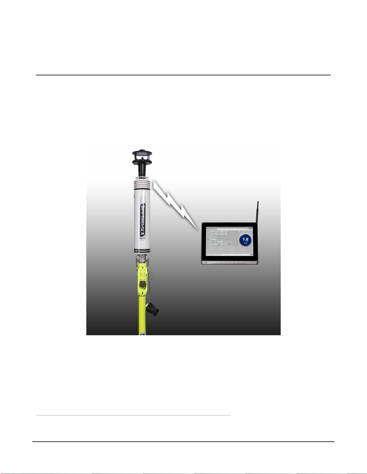
1. System description
The WEATHERPAK®M1measures wind speed and wind direction, air temperature, relative
humidity, and barometric pressure. In addition, the WEATHERPAKM calculates the wind stability
class and provides location information. Atmospheric conditions are sampled every second and
the system computes a 5-minute running average. Data is then transmitted every 30 seconds to
the display and plume model.
FIGURE 1-1. WEATHERPAKM with INTERCEPT Display
1
WEATHERPAK is a registered trademark of Campbell Scientific.
WEATHERPAK M 1
Page 12

WEATHERPAKM was specifically designed for use by Hazardous Materials Responders. The
following is a list of some of the features that make the WEATHERPAKM unique:
l WEATHERPAKM features an advanced electronic interface and unique automatic
networking capability. The advanced electronic interface allows the use of GPS and
SmartDetect™ and future enhancements.
l The ultrasonic wind sensor has no moving parts, is very accurate (particularly at very low
wind speeds), and does not require periodic calibration.
WEATHERPAKM features a multi-function, 10.1-inch full colour, flat panel touch
l
screen display (INTERCEPT®1 Display). Multiple windows display data from different
WEATHERPAKM weather stations.
Automatically updates CAMEO®/ALOHA®2 and most other plume modelling
l
software programs.
l Built-in electronic compass allows the WEATHERPAKM to be set up in any orientation –
will automatically determine True North and give you true wind direction.
l Set-up time is less than one minute.
l
The electrical connections are designed to be intrinsically safe and the housing and tower
are constructed of 6061-T6 aluminium, a non-corrosive and non-sparking alloy.
l Designed to withstand decontamination procedures. The WEATHERPAKM housing is
double O-ring sealed and dried with a desiccant to protect the electronics against
moisture.
l All electronics are grounded at a single point to protect the WEATHERPAKM against EMI
(electro-magnetic interference) and RFI (radio frequency interference), thus assuring
reliable data and transmission.
This manual will familiarize you with the installation, operation, and maintenance of the
WEATHERPAKM. Please read all of the instructions before attempting to operate or troubleshoot
the system.
1
INTERCEPT is a registered trademark of Campbell Scientific.
2
Both ALOHA and CAMEO are registered by National Oceanic and Atmospheric Administration (NOAA) U.S.
Department of Commerce FEDERAL AGENCY UNITED STATES.
WEATHERPAK M 2
Page 13

WEATHERPAKM components:
l Ultrasonic wind sensor
l Barometer
l Air temperature and relative sensor
l INTERCEPT display
l Display power supply and power cable
l Receiver/display box
l Communications options:
o
Wired serial—includes serial cable
o
UHF radio—includes two UHF radios, narrow band antenna, and cables
o
Spread spectrum radio—includes two spread spectrum radios, spread antenna, and
cable
l Mounting options:
o Portable 3 metre quick-deploy tripod—includes tripod and carry case
o Portable telescopic mast—includes mast and carry case
l WEATHERPAKM carry case
l WEATHERPAKM Quick Deploy Guide for assembly and ALOHA
2. Siting and setup
2.1 Siting considerations
The following siting considerations must be addressed:
2.1.1 Compass accuracy
The WEATHERPAKM contains an electronic compass for automatic alignment to True North. To
prevent erroneous compass readings, install the WEATHERPAKM at least 30 metres (99 feet)
laterally from large vans, buses, cranes, or other large magnetic objects. (The top of a van is
suitable, but next to it is not an ideal location).
WEATHERPAK M 3
Page 14

2.1.2 Proper wind measurement
Locate the WEATHERPAKM away from obstructions such as trees and buildings. The distance
between wind sensors and the nearest obstruction should be ten times the height of the
obstruction.
2.1.3 Radio transmission
Deploy the WEATHERPAKM as close as safety permits to the hot zone. The WEATHERPAKM
UHF radio has a range of 5 to 7 miles line-of-sight.
CAUTION:
Do not attempt to transmit through structures containing steel, or through hills.
2.1.4 GPS operation
There is a GPS receiver inside the INTERCEPT display and a GPS receiver inside the
WEATHERPAKM. These GPS receivers work together and provide data to the SmartDetect™
firmware, which in turn furnishes direction and distance information for additional
WEATHERPAKM stations operating in the vicinity.
The GPS in the INTERCEPT display must be connected to an external GPS antenna. The receiver
will automatically begin to search for and track GPS satellite signals at power up. The antenna
must have good exposure to the sky.
The performance of a GPS receiver at power-up is determined largely by the availability and
accuracy of the satellite ephemeris data and the availability of a GPS system almanac. When the
WEATHERPAKM is powered-up, the GPS searches for satellites from a cold start (no almanac).
The GPS will begin to compute position solutions within the first two minutes.
NOTE:
Immediately power up the WEATHERPAKM system as soon as you arrive on site to allow the
GPS to find the satellite and computer position.
2.2 System assembly
2.2.1 INTERCEPT display connections
The INTERCEPT display is only available for the WEATHERPAKM. It contains the radio receiver.
The radio antenna receives the signal from the WEATHERPAKM using narrow band UHF or
spread spectrum. In addition, a GPS antenna and electronics allow the WEATHERPAKM location
to be shown in relation to the display location.
WEATHERPAK M 4
Page 15

1. Connect the external GPS and radio antennas to the appropriate connectors on the side of
the INTERCEPT display (see FIGURE 2-1 (p. 5)).
FIGURE 2-1. Side of INTERCEPT display
2. When outputting data to the CAMEO/ALOHA plume modelling software, connect the USB
to serial data cable. (The Ethernet connection will only be used in rare instances where the
INTERCEPT display will be connected to a network).
3. Plug the INTERCEPT display power supply into an AC power source then insert the power
supply barrel connector into the power jack on the bottom of the display and tighten.
FIGURE 2-2. Bottom of INTERCEPT display
WEATHERPAK M 5
Page 16

4. The power indicator light on the bezel illuminates as the display starts up. The INTERCEPT
application will automatically launch and begin receiving data from any WEATHERPAKM
units available.
FIGURE 2-3. Front of INTERCEPT display
2.2.2 Connecting to a computer with USB to serial converter
The INTERCEPT display comes with a USB-to-serial converter cable. Use this cable to connect the
display to a computer or server. The INTERCEPT software can be configured to output ALOHA
messages to the display USB ports.
2.2.3 Connecting to a computer with the Ethernet port
This method is to be employed only if the INTERCEPT display must be connected to a network.
Please contact Campbell Scientific for further information. Refer to the About this manual page
at the beginning of this document for the procedure of returning components to Campbell
Scientific.
WEATHERPAK M 6
Page 17

2.2.4 Tripod and WEATHERPAKM setup
Assemble the tower in the following manner:
1. Insert and lock the legs onto the bottom section of the tower, forming the tower tripod
base.
2. Align the slot on the WEATHERPAKM with the guide pin on the quick release and push
straight in. The cam lock provides a precision sealed fit and may require an extra push to
seat the WEATHERPAKM properly.
CAUTION:
DO NOT screw the WEATHERPAKM onto the cam lock connector.
WEATHERPAK M 7
Page 18

3. Once the weather station is properly seated, press the arms of the cam lock down to assure
a tight fit. The battery indicator light (on the tower junction box) should illuminate when
the WEATHERPAKM is properly seated into the cam lock.
4. Place the entire unit (upper tower section and WEATHERPAKM) onto the tripod, engage
the twist-lock and turn clockwise a quarter turn.
5. The WEATHERPAKM is now running and sampling data. When the WEATHERPAKM is
removed from the cam lock connector, it will stop sampling and shut itself off.
WEATHERPAK M 8
Page 19

FIGURE 2-4. Tower setup
WEATHERPAK M 9
Page 20

3. System operation
Once set up, the WEATHERPAKM automatically begins sampling weather conditions and
transmits data to the INTERCEPT display every 30 seconds. The INTERCEPT display takes
approximately 20 to 30 seconds to complete a startup routine. When this process is complete,
the plume modelling software requires five minutes of data before a valid plume can be
presented.
3.1 INTERCEPT display functions and operation
The INTERCEPT display is configured at the factory with the ID of the accompanying
WEATHERPAKM and display units. The display can receive and display data from multiple
WEATHERPAKM units, but the factory configured ID will act as the primary WEATHERPAKM.
The touch screen provides access to multiple windows that display weather data in a variety of
ways. There are two sections: Observer and Maintenance (click on either at the upper right
corner). The Observer section is where weather data is displayed. The Maintenance section is
where system status can be checked. In the Observer section there is a tab for Weather Summary
and WEATHERPAK. Additional WEATHERPAKM stations may be added by the user, and a new
tab would be added.
3.2 Observer section
3.2.1 Weather Summary
The Weather Summary tab shows the current, instantaneous values from all reporting
WEATHERPAKM systems available to the INTERCEPT display.
WEATHERPAK M 10
Page 21

FIGURE 3-1. Weather summary
3.2.2 WEATHERPAK
The WEATHERPAK tab is where current values from the primary WEATHERPAKM system are
displayed. Data from additional WEATHERPAKM systems are displayed in subsequent tabs,
identified by the WEATHERPAKM ID.
FIGURE 3-2. Current values from the primary WEATHERPAKM system
WEATHERPAK M 11
Page 22

3.2.3 Display theme
The display can be viewed in night or day theme. To change theme, click Display in the upper left
corner. A pop-up window will appear. Choose the desired theme then click Submit.
FIGURE 3-3. Display pop-up window
WEATHERPAK M 12
Page 23

3.2.4 Help
Click the Help tab and select Contents to display the Help Contents. Navigate to any section to
get instructions and explanations of the software.
FIGURE 3-4. Help contents
WEATHERPAK M 13
Page 24

3.2.5 Logs
Click the Logs tab and select View Logs. The Log View pop-up will display system data logs.
FIGURE 3-5. Logs
3.2.6 Graphs
Click the Graphs tab and select WEATHERPAK to display the desired graph.
FIGURE 3-6. Graphs
WEATHERPAK M 14
Page 25

3.3 Maintenance
3.3.1 Maintenance Dashboard
Select the Maintenance Dashboard tab to see a graphical display of the overall system status.
Green lights indicate normal conditions. A red light indicates an alarm for that particular item.
Click the icon for detailed information about the alarm.
FIGURE 3-7. Maintenance Dashboard
FIGURE 3-8. Maintenance Dashboard with message displayed
WEATHERPAK M 15
Page 26

3.3.2 Settings
Select the Settings tab to adjust specific system information.
FIGURE 3-9. Settings
4. WEATHERPAKM and plume
modelling software
When the WEATHERPAKM is assembled and operational and a computer is connected to the
INTERCEPT display, real-time data is available to run air dispersion plume modelling software.
The following shows of the steps taken to produce an ALOHA plume model on a computer. This
section assumes the user is familiar with ALOHA and that the program is properly loaded onto
the computer. Campbell Scientific recommends consulting the ALOHA website and/or a certified
CAMEO/ALOHA instructor for training, program details, and limitations.
1. Click the ALOHA desktop icon or select ALOHA from the Windows® Programs menu. An
Air Model Limitations dialogue box will appear with important notes on program
limitations. Read and click OK.
WEATHERPAK M 16
Page 27

2. Confirm that your Site Data information provided in the Text Summary window is correct. If
required, use the SiteData drop-down menu to change data.
3. Go to SetUp > Chemical and select the appropriate chemical.
4. Select SetUp > Atmospheric > SAM Station to display series of dialogue boxes that require
user observations or assumptions.
NOTE:
Relative humidity is not captured automatically by the ALOHA model but may be
entered manually using data from the WEATHERPAKM display.
5. (Optional) To confirm that WEATHERPAKM data is being delivered to ALOHA, go to SAM
Options > Processed Data and the Processed SAM Data window will display the data
delivered to ALOHA.
NOTE:
The user gets a warning message in both the Text Summary and Processed SAM Data
windows if the WEATHERPAKM has been collecting data for less than five minutes.
6. ALOHA requires the SAM station to be operating for five minutes before selecting the
source of release (tank, pipe, direct, etc.). Go to SetUp > Source and select the leak source
such as tank. A series of dialogue boxes will appear requiring user observations or
assumptions.
7. Select Display > Threat Zone and the Level of Concern window will display the default
ERPG ranges. Select OK to show the plume footprint. Displaying the footprint in ALOHA is
essential before the plume can be overlaid on a MARPLOT® or other street map.
WEATHERPAK M 17
Page 28

8. (Optional) Select the Display menu to produce graphs for source strength and
concentration.
FIGURE 4-1. ALOHA window
WEATHERPAK M 18
Page 29

9. Select the Sharing menu to plot the plume onto a MARPLOT (or other) map. As weather
conditions change, the plume size and position will change on the map, shortly after the
WEATHERPAKM provides updated data.
NOTE:
MARPLOT software requires that the ALOHA window overlay the map window for the
map-plume to update automatically (FIGURE 4-2 (p. 19)).
FIGURE 4-2. ALOHA with MARPLOT map
WEATHERPAKM reads the sensors every second and calculates five-minute running averages.
The running averages are included with the INSTANTANEOUS data on the INTERCEPT display,
and subsequently the plume model. In addition, the WEATHERPAK calculates Sigma Theta,
which is an air turbulence measurement that affects the mixing or dispersion of a chemical in the
atmosphere. Sigma Theta is also referred to as stability.
The INSTANTANEOUS data is the last direct sensor reading prior to the thirty-second update and
the battery voltage. The operator may detect a trend such as wind shift by comparing the 5
MINUTE RUNNING AVERAGE and INSTANTANEOUS data. The WEATHERPAKM battery voltage
is also transmitted.
NOTE:
Replace the WEATHERPAKM batteries when the battery voltage falls below 10.7 VDC.
To display the ASCll data being sent by the WEATHERPAKM, go to Main > SAM Options and
select Raw Data. The data should be similar to the following:
421, 0.9, 225, 1.0, 23.9, 1.0, 226, 23.9, 14.0, 1917, 999, 46, 2536
WEATHERPAK M 19
Page 30

Most of these numbers also appear in the Processed SAM Data window in ALOHA. The
differences are no labels and some additional numbers. In addition, this raw data is delivered in
metric units (millibars, m/s, °C), whereas the processed data is converted to standard English
units (inches, MPH, °F).
Two checksums are performed to ensure the message was sent correctly. The computer adds up
the ASCII value of the data line (each character, such as numbers, letters, and punctuation, have
a numeric value universal to all computers) to make sure the computer received the same
number that the WEATHERPAKM transmitted.
4.1 ALOHA data line interpretation
The data line fields are as follows:
ID, MW, MD, ST, AT, SI, DI, TI, BV, CKSUM1, BP, RH, CKSUM2
ID –
MW –
MD –
ST –
AT –
SI –
DI –
TI –
BV –
CKSUM1 –
BP –
RH –
CKSUM2 –
WEATHERPAKM
5 minute averaged wind speed in metres per second
5 minute averaged wind direction in degrees
Stability class in degrees
5 minute averaged air temperature in degrees Celsius
Instantaneous wind speed in metres per second
Instantaneous wind direction in degrees
Instantaneous air temperature in degrees Celsius
Battery voltage in volts
First checksum
Barometric pressure in millibars
Relative humidity in percent
Second checksum
unique identification number
WEATHERPAK M 20
Page 31

5. Maintenance
NOTE:
All factory repairs and recalibrations require a returned material authorization (RMA) number
and completion of the “Statement of Product Cleanliness and Decontamination” form. Refer
to the About this manual page at the beginning of this document for more information.
5.1 Periodic maintenance schedule
Perform routine maintenance on the WEATHERPAKM every 12 to 24 months to ensure that the
overall system and its sensors are within specification. In addition, the entire WEATHERPAK
should be examined for wear, damage, or other non-conforming variances.
5.2 Troubleshooting
CAUTION:
Taking the WEATHERPAKM or the INTERCEPT Display apart will void the warranty. If the
following procedures do not solve the problem, contact Campbell Scientific.
5.2.1 WEATHERPAKM
When completely assembled, the WEATHERPAKM system automatically powers up, locates True
North, and begins sampling the atmospheric conditions; it then transmits weather data every 30
seconds. If it does not, check the following:
l Confirm the WEATHERPAKM is properly secured in the cam lock connector on the tripod
tower.
l Check the batteries in the tower. The red LED voltage indicator light on the tripod tower
will remain illuminated when the battery voltage is higher than 10.7 VDC. If the LED
indicator is not illuminated or if it is flashing, replace the batteries with fresh alkaline Dcells. When replacing tower batteries, use only high-quality alkaline batteries.
CAUTION:
Do not use rechargeable or bargain batteries.
l Check the fuse. The in-line fuse holder is in the junction box at the top of the tripod tower.
Access the fuse by removing the two screws on the junction box cover. If the fuse is blown,
WEATHERPAK M 21
Page 32

replace with an AGC3 fuse. If the fuse blows repeatedly, contact Campbell Scientific. See
Replacing tower batteries and fuse (p. 23).
If the INTERCEPT display does not illuminate shortly after the on/off button is pressed, check the
following:
l Be sure the INTERCEPT Display is plugged in and turned on. Double check the power cord
connections at the wall, power supply and bottom of the INTERCEPT Display. If this does
not correct the problem, contact Campbell Scientific.
5.2.2 Data receipt
If the WEATHERPAKM data does not update on the INTERCEPT display and the WEATHERPAK is
within range, check the following:
l Double check the power cord. Be certain the INTERCEPT display is plugged in and turned
on. Check the power indicator light on the On/Off button on the front panel.
l Make certain you have direct line-of-sight to the WEATHERPAKM, that it is within 5 to 7
miles, and not blocked by an obstruction such as hills, vehicles, or steel buildings.
l Check to see that both the WEATHERPAKM antenna and the receiving antenna are
securely connected.
l Reset the system by removing the WEATHERPAKM from the cam lock connector on the
tripod tower. Wait 10 seconds, then replace the WEATHERPAKM on the tower.
l Check the tripod battery voltage and ensure the batteries are properly aligned (positive
towards the top of the tower). Replace batteries if necessary. (Replacing tower batteries and
fuse (p. 23).)
5.2.3 Computer
If the INTERCEPT display shows data, but your computer is not receiving the data, do the
following:
l Check all the connections from the INTERCEPT display to the computer.
l Ensure that the most recent version of ALOHA software is installed on the computer. Some
earlier versions of ALOHA (e.g. ver. 5.2.1) need to be upgraded to work with an automatic
weather station like the WEATHERPAKM. The U.S. EPA provides CAMEO/ALOHA software
downloads, support, and information at its web site: www.epa.gov/cameo.
l Ensure that the virtual COM port configuration is not being used by another device.
ALOHA must receive data on COM 1, 2, 3 or 4. If these ports are used by other devices or if
Windows® has assigned ALOHA a port other than COM 1, 2, 3 or 4, the software will not
WEATHERPAK M 22
Page 33

receive the weather station. For more information, refer to WEATHERPAKM USB
connection and set up (p. 27).
Error messages while running the plume model are coming from the plume modelling software.
If you get an error message:
l Consult the CAMEO/ALOHA web site: www.epa.gov/cameo.
l Contact Campbell Scientific. Although not certified CAMEO/ALOHA trainers or
representatives, we may be able to help.
5.3 Replacing tower batteries and fuse
WARNING:
Do not leave batteries in tower when storing or shipping tower assembly. Batteries may leak
causing damage to upper tower section.
5.3.1 Tower batteries
The WEATHERPAKM uses ten alkaline D-cell batteries, located in the upper vertical section of
the tower. Rechargeable and bargain batteries do not perform well in the WEATHERPAKM.
Always use high quality alkaline batteries. (See FIGURE 5-1 (p. 23).)
FIGURE 5-1. Battery Replacement
Remove the battery plug using a large screwdriver. Insert the blade of the screwdriver into the
slotted plug, gently push the spring-loaded plug, then rotate the plug one-quarter turn either
direction. The plug and spring will come out followed by the batteries. Insert the new batteries by
tilting the tower section at an angle of approximately 45 degrees. A steeper angle will cause the
batteries to impact the top terminal too forcefully denting the positive terminal of the batteries.
This may cause the batteries to leak or create a faulty electrical connection. Slide the batteries in,
positive end first, then replace the spring-loaded plug using the reverse procedure.
WEATHERPAK M 23
Page 34

The red LED voltage indicator light on the tripod tower will remain illuminated when the battery
voltage is higher than 10.7VDC. View the precise battery voltage using the Weatherpak Status
window on the INTERCEPT display. If monitoring multiple WEATHERPAKM stations, ensure that
the status window for the appropriate WEATHERPAKM station is viewed by using the ALOHA
plume model. To use ALOHA, open it on the computer, and go to MISC > Processed SAM Data.
One of the items shown is battery voltage. With new batteries installed, the voltage should be
between approximately 13 and 15 volts.
5.3.2 Tower fuse
The in-line fuse is located in the tower junction box (see FIGURE 5-2 (p. 24)). Gain access to the
fuse holder by removing the two machine screws on the junction box faceplate; then carefully
separate the faceplate from the junction box. Inspect the in-line fuse and replace if necessary
with an AGC3 fuse.
FIGURE 5-2. Fuse location
WEATHERPAK M 24
Page 35

Appendix A. Vehicle mounting
a WEATHERPAKM
The WEATHERPAKM weather station is primarily designed to be deployed in (or near) a Hazmat
hot zone and the system includes a portable 3-metre tower for this purpose. However,
customers have found it convenient to mount the system on a vehicle (or trailer) when the
WEATHERPAKM is used for other applications, such as wildland or structure fires. Any
WEATHERPAKM can be vehicle mounted; typically, one of the following methods is used:
1. Campbell Scientific offers a professional, turnkey vehicle mounting solution for the
WEATHERPAKM. We have modified a side mount telescopic pole (Model 530), provided
by Fire Resources Corporation, Inc., a premier manufacturer of emergency lighting
products, to accept the WEATHERPAKM. (See FIGURE A-1 (p. 25).) Please contact the
Campbell Scientific Sales Department for pricing and more information.
FIGURE A-1. Side mount “push-up” mast
WEATHERPAK M 25
Page 36

2. Campbell Scientific also sells an accessory that allows the user to adapt the
WEATHERPAKM to a mast of your choice. (See FIGURE A-2 (p. 26).) The WEATHERPAKM
Vehicle Adapter is a cam lock Quick-Release with a male 1 1/2-inch NPT (national pipe
thread) on the bottom and 25-foot cable.
FIGURE A-2. Vehicle mount adapter
Both options arrive with two-conductor bare wire connections that must be terminated on a
12VDC source. While we are available to advise you, it is ultimately the customers’ responsibility
to determine the best way to install these devices on their vehicle.
To use these mounting solutions, the WEATHERPAKM must be serial number 1325 or higher,
have radio telemetry, and a 17-pin cam lock connector.
WEATHERPAK M 26
Page 37

Appendix B. WEATHERPAKM
USB connection and set up
Depending upon the type of connection, when the WEATHERPAKM system is first connected to
a computer, Windows® automatically establishes a communications link between the
WEATHERPAKM INTERCEPT display and the computer, which allows data to pass to the plume
model or other software. USB or Ethernet connections may require additional drivers.
1. Verify that data is being received from the WEATHERPAKM. Start ALOHA on the computer
and set the COM port to the com port the cable is plugged in to. Be certain the most recent
version of ALOHA is running. Check or download the most current version from the U.S.
EPA web site: www.epa.gov/cameo.
2. With the WEATHERPAKM set up and transmitting, open the ALOHA Text Summary
window. It should look similar to this:
WEATHERPAK M 27
Page 38

If errors appear on this window, verify the computer is receiving data. To do this, in ALOHA,
go to SAM Options on the top menu bar and select Raw Data. A window displays a string
of numbers similar to the following. The data line should refresh every 30 seconds (window
blinks and overwrites the previous data string).
WEATHERPAK M 28
Page 39

Appendix C. Important information for North American users
The following Note pertains to WEATHERPAKM stations using the wired serial communication
option.
NOTE:
This equipment has been tested and found to comply with the limits for a Class A digital
device, pursuant to part 15 of the FCC Rules. These limits are designed to provide reasonable
protection against harmful interference when the equipment is operated in a commercial
environment. This equipment generates, uses, and can radiate radio frequency energy and, if
not installed and used in accordance with the instruction manual, may cause harmful
interference to radio communications. Operation of this equipment in a residential area is
likely to cause harmful interference, in which case the user will be required to correct the
interference at his own expense.
The following Note and Warning pertain to WEATHERPAKM stations using the UHF or 900MHz
radio options.
NOTE:
This equipment has been tested and found to comply with the limits for a Class B digital
device, pursuant to part 15 of the FCC Rules. These limits are designed to provide reasonable
protection against harmful interference in a residential installation. This equipment
generates, uses and can radiate radio frequency energy and, if not installed and used in
accordance with the instructions, may cause harmful interference to radio communications.
However, there is no guarantee that interference will not occur in a particular installation. If
this equipment does cause harmful interference to radio or television reception, which can be
determined by turning the equipment off and on, the user is encouraged to try to correct the
interference by one or more of the following measures:
l Reorient or relocate the receiving antenna.
l Increase the separation between the equipment and receiver.
WEATHERPAK M 29
Page 40

l Connect the equipment into an outlet on a circuit different from that to which the
receiver is connected.
l Consult the dealer or an experienced radio/TV technician for help.
WARNING:
Changes or modifications to this device not expressly approved by Campbell Scientific could
void the user’s authority to operate this equipment.
WEATHERPAK M 30
Page 41

Page 42

Campbell Scientific regional offices
Australia
Location:
Phone:
Email:
Website:
Brazil
Location:
Phone:
Email:
Website:
Canada
Location:
Phone:
Email:
Website:
China
Location:
Phone:
Email:
Website:
Garbutt, QLD Australia
61.7.4401.7700
info@campbellsci.com.au
www.campbellsci.com.au
São Paulo, SP Brazil
11.3732.3399
vendas@campbellsci.com.br
www.campbellsci.com.br
Edmonton, AB Canada
780.454.2505
dataloggers@campbellsci.ca
www.campbellsci.ca
Beijing, P. R. China
86.10.6561.0080
info@campbellsci.com.cn
www.campbellsci.com.cn
France
Location:
Phone:
Email:
Website:
Vincennes, France
0033.0.1.56.45.15.20
info@campbellsci.fr
www.campbellsci.fr
Germany
Location:
Phone:
Email:
Website:
Bremen, Germany
49.0.421.460974.0
info@campbellsci.de
www.campbellsci.de
India
Location:
Phone:
Email:
Website:
New Delhi, DL India
91.11.46500481.482
info@campbellsci.in
www.campbellsci.in
South Africa
Location:
Phone:
Email:
Website:
Stellenbosch, South Africa
27.21.8809960
sales@campbellsci.co.za
www.campbellsci.co.za
Thailand
Location:
Phone:
Email:
Website:
UK
Location:
Phone:
Email:
Website:
USA
Location:
Phone:
Email:
Website:
Bangkok, Thailand
66.2.719.3399
info@campbellsci.asia
www.campbellsci.asia
Shepshed, Loughborough, UK
44.0.1509.601141
sales@campbellsci.co.uk
www.campbellsci.co.uk
Logan, UT USA
435.227.9120
info@campbellsci.com
www.campbellsci.com
Costa Rica
Location:
Phone:
Email:
Website:
San Pedro, Costa Rica
506.2280.1564
info@campbellsci.cc
www.campbellsci.cc
Spain
Location:
Phone:
Email:
Website:
Barcelona, Spain
34.93.2323938
info@campbellsci.es
www.campbellsci.es
 Loading...