

Page 1

INSTRUCTION MANUAL
Vosponder Voice Radio Interface
for Use with Campbell Scientific
Dataloggers
3/05
Copyright (c) 2004-2005
Campbell Scientific, Inc.
Page 2

Warranty and Assistance
The VOSPONDER VOICE RADIO INTERFACE is warranted by
CAMPBELL SCIENTIFIC, INC. to be free from defects in materials and
workmanship under nor mal use and service for twelve (12) months from date of
shipment unless specifi ed otherwise. Batteries have no warranty. CAMPBELL
SCIENTIFIC, INC.'s obligation under this warranty is limited to repairing or
replacing (at CAMPBELL SCIENTIFIC, INC.'s option) defective products.
The customer shall assume all costs of removing, reinstalling, and shipping
defective products to CAMPBELL SCIENTIFIC, INC. CAMPBELL
SCIENTIFIC, INC. will return such products by surface carrier prepaid. This
warranty shall not apply to any CAMPBELL SCIENTIFIC, INC. products
which have been subjected to modification, misuse, neglect, accidents of
nature, or shipping damage. This warranty is in lieu of all other warranties,
expressed or implied, including warranties of merchantability or fitness for a
particular purpose. CAMPBELL SCIENTIFIC, INC. is not liable for special,
indirect, incidental, or consequential damages.
Products may not be returned without prior authorization. The following
contact information is for US and International customers residing in countries
served by Campbell Scientific, Inc. directly. Affiliate companies handle repairs
for customers wi thin their territories. Please visi t www.campbellsci.com to
determine which Campbell Scientific company serves your country. To obtain
a Returned Materials Authorization (RMA), contact CAMPBELL
SCIENTIFIC, INC., phone (435) 753-2342. After an applications engineer
determines the nature of the problem, an RMA number will be issued. Please
write this number clearly on the outside of the shipping container.
CAMPBELL SCIENTIFIC's shipping address is:
CAMPBELL SCIENTIFIC, INC.
RMA#_____
815 West 1800 North
Logan, Utah 84321-1784
CAMPBELL SCIENTIFIC, INC. does not accept collect calls.
Page 3

Disclaimer
This manual is intended to present application, product, and technical data to
assist the user in selecting and using Vosponder data to speech translation
devices. However, users should independently evaluate the suitability of, and
test each product for their application. DACOM TECHNOLOGIES INC.,
makes no warranties as to the accuracy or completeness of the information in
this manual and disclaims any liability resulting from its use. In no case will
DACOM TECHNOLOGIES INC., be liable for any incidental, indirect, or
consequential damages arising from the sale, resale, use, or misuse of its
products.
DACOM TECHNOLOGIES INC., reserves the right to change or update,
without notice, any information contained in this manual; to change, without
notice, the design, construction, materials, processing, or specification of any
products; and to discontinue or limit production or distribution of any products.
Without express written consent, DACOM TECHNOLOGIES INC., does not
authorize the use of any of its products as components in nuclear facility
applications, aerospace, or in critical life support systems or devices where the
failure of the product in the application might be reasonably expected to cause
the failure or malfunction of the system or device.
SDI-12 is not currently registered by any professional society, standards
organization, or Government agency. Document copies, current document
status, and other information may be obtained by contacting the SDI-12
Support Group at 165 East 500 South, River Heights, Utah 84321, PHONE:
435-752-4200, FAX: 435-752-1691.
Page 4

This is a blank page.
Page 5

Vosponder Table of Contents
PDF viewers note: These page numbers refer to the printed version of this document. Use
the Adobe Acrobat® bookmarks tab for links to specific sections.
Overview.................................................................... OV-1
1. Hardware..................................................................1-1
1.1 SDI-12 Bus and Power Input ................................................................ 1-1
1.2 Two-Way Radio Interface..................................................................... 1-2
1.3 RS-232C Terminal Interface................................................................. 1-3
2. Programming the Datalogger..................................2-1
2.1 Send Data Command............................................................................ 2-2
2.2 Speak Text Command........................................................................... 2-4
2.2.1 ASCII Table................................................................................ 2-5
2.3 Speak Now Command........................................................................... 2-6
3. Developing the Voice Image File............................3-1
3.1 Purpose of the Voice Image.................................................................. 3-1
3.2 Creating a Voice Image File................................................................. 3-1
3.3 Using the Voice Image Development Software.................................... 3-3
3.3.1 Building the Voice Image File .................................................... 3-4
3.3.2 Editing the Voice Image File.......................................................3-5
4. Vosponder Configuration and Progr amming ........4-1
4.1 Communicating with the Vosponder..................................................... 4-1
4.2 Entering Commands.............................................................................. 4-2
4.2.1 Main Menu Command................................................................. 4-3
4.2.2 View Menu Commands............................................................... 4-5
4.2.3 Edit Menu Commands ................................................................. 4-7
4.2.4 Uploaded Menu (Transfer the Voice Image File......................... 4-9
4.3 Configuring the Vosponder Settings................................................... 4-10
4.3.1 Steps for Configuration and Testing the Vosponder................. 4-10
5. Testing and Troubleshooting..................................5-1
5.1 ERROR Codes...................................................................................... 5-1
5.2 Frequently Asked Questions ................................................................. 5-1
Appendices
A. SDI-12 Interface......................................................A-1
A.1 SDI-12 Modes......................................................................................A-1
i
Page 6

Vosponder Table of Contents
B. Cabling and Connections ......................................B-1
C. Audio Level Controls .............................................C-1
D. Terminal Commands Menu Tree ...........................D-1
E. The Anatomy of the Voice Image File ...................E-1
F. Datalogger Program Example................................ F-1
G. Specifications.........................................................G-1
A.2 SDI-12 Slave Mode Commands.......................................................... A-1
A.3 Master Mode for SDI-12 Sensors........................................................ A-2
A.4 SDI-12 Master Mode........................................................................... A-2
Figures
1-1. J1, SDI-12 Bus Interface Connector ....................................................1-1
1-2. J6, Radio Interface Port .......................................................................1-2
1-3. J5, RS-232C Terminal Interface ..........................................................1-3
4-1 Terminal Command Mode - Main Menu Prompt..................................4-2
4-3. Terminal Command Mode - View Menu Prompt (With Help)............4-5
4-4. Terminal Command Mode - Edit Menu Prompt (With Help...............4-7
4-5 Terminal Command Mode - View | Image | Voice Screen.................. 4-11
A-1. SDI-12 Slave Mode Commands......................................................... A-1
B-1. Terminal Interface Cable (Null Modem............................................. B-1
B-2. SDI-12 Data and Power Interface Connector..................................... B-1
B-3. RS-232C Terminal Interface Connector............................................. B-1
B-4. Radio Interface Connector (Partial Schematic).................................. B-2
C-1. Audio Level Controls......................................................................... C-1
Table
5-1. Terminal Error Codes..........................................................................5-1
Examples
2-1. Program to send three data values to the Vosponder ...........................2-2
2-2. Character Count...................................................................................2-3
2-3. Program to send seven data values to the Vosponder..........................2-3
2-4. Program to send text string to the Vosponder......................................2-4
2-5. Program to initiate immediate broadcast of the most recent
E-1. Voice image file..................................................................................E-1
data values.....................................................................................2-6
ii
Page 7

Vosponder Overview
The Vosponder converts raw digital data input from a datalogger to natural
human speech. The model VSP3 is designed to connect via an industry
standard SDI-12 serial digital interface to data acquisition systems such as the
Campbell Scientific, Inc. CR510, CR10X, and CR23X series dataloggers. The
Vosponder also interfaces to a two-way radio system to broadcast the
information to the user over the radio link.
The voice message broadcast sequence starts when the selected data values are
sent from the datalogger and stored temporarily in the Vonsponder’s memory.
The Vosponder uses what is called a “voice image” to determine what text
string to associate with each data value, how to speak the decimal point, and
how many numbers after the decimal point to speak. The combined text and
data values are then broadcast over the radio link.
A voice message can be initiated in several ways.
• Based on a DTMF tone sequence from a radio handset - Anyone with a
two-way radio which has DTMF features, can request the current data
from a datalogger. This is done by entering a pre-set key press sequence
on the radio handset’s keypad. The Vosponder is also addressable, so a
user may request data from multiple stations simply by entering the
different numeric key press sequences (DTMF codes) that are assigned to
various Vosponders.
• Based on a user set interval - This option allows for transmission of the
stored data at predefined intervals (i.e., you can have your data broadcast
every 15 minutes).
• Based on events or conditions - Standard voice messages as well as voice
alarm messages can be broadcast based on events (i.e., if the battery
voltage gets low, the station can report a low battery alarm).
Programming the datalogger and conf iguring the Vosponder requires four
steps. One of the steps is covered in each of the first four sections of this
manual.
1. Hardware connections to the datalogger and radio (Section 1)
2. Programming the datalogger to output the data values to the
Vosponder (Section 2)
3. Developing a voice image file for the Vosponder (Section 3)
4. Setup and testing of the Vosponder (Section 4)
Two modes of operation are supported. These modes relate to the SDI-12
specification and are referred to as ‘slave’ and ‘master’ mode.
The Vosponder defaults to the SDI-12 slave mode. In this mode the
Vosponder responds to commands issued by the datalogger over the SDI-12
bus. This is the method best used with Campbell Scientific dataloggers.
OV-1
Page 8

Vosponder Overview
Several special “extended SDI-12 commands” are used to deliver data from the
datalogger to the Vosponder for verbalization through the radio telemetry link.
The SDI-12 master mode can be used to interface the Vosponder directly to
any SDI-12-compatible sensor or other SDI-12 compatible devices. Some
information about this mode is covered in Appendix A. However, detailed use
and configuration instructions are not included in this manual. If you want to
use the master mode, please contact DACOM Technologies at (435) 755-0300
or request this information by e-mail via support@dacomtechnologies.com.
OV-2
Page 9
Section 1. Hardware
► 1. Hardware connections to the datalogger and radio (Section 1)
2. Programming the datalogger to output the data values to the
Vosponder (Section 2)
3. Developing a voice image file for the Vosponder (Section 3)
4. Setup and testing of the Vosponder (Section 4)
Understanding how to connect the various hardware components is the first
step in the setuup process. The Vosponder has three input connectors. These
include an SDI-12 bus interface, a radio interface, and an RS-232C terminal
serial interface. Before the Vosponder can be used it must be connected to a
datalogger, a power supply, and a radio. The RS-232C serial interface is only
used when the Vosponder is connected directly to a computer for
configuration. Following is a description of each connection and its purpose.
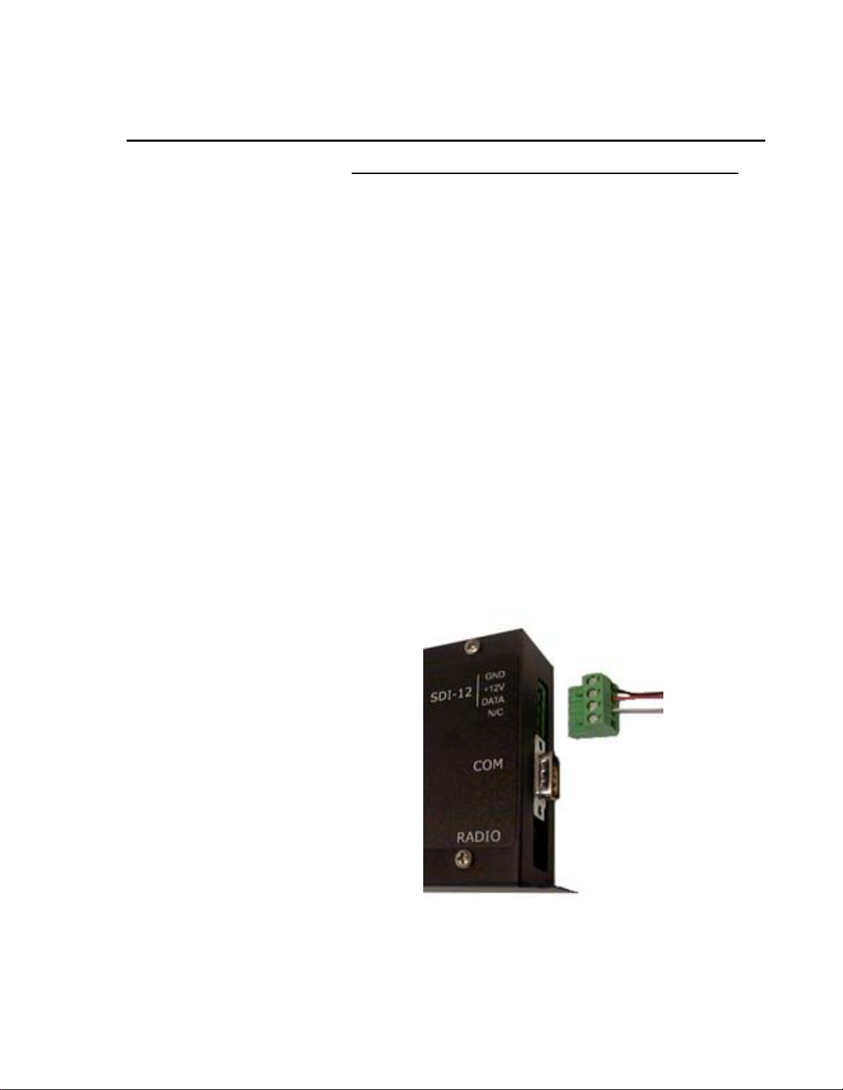
1.1 SDI-12 Bus and Power Input
This connection provides an interface to the datalogger and power to the
Vosponder. The Vosponder is designed to operate from the nominal +12 Volt
DC provided via the SDI-12 interface cable. J1 is a four place, right angle,
5 mm screw terminal that facilitates the mechanical connections as shown in
Figure 1-1. A schematic of the connector can be found in Appendix B, Figure
B-2.
FIGURE 1-1. J1, SDI-12 Bus Interface Connector
1-1
Page 10
Section 1. Hardware
The SDI-12 interface cable is wired between Vosponder and a CSI datalogger
as follows:
Vosponder Color Purpose CSI Datalogger
Terminal 1 Black Ground G
Terminal 2 Red +12 VDC 12V
Terminal 3 White Data Control Port
Terminal 4 No Connection
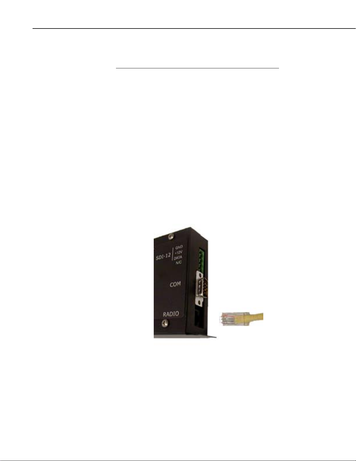
1.2 Two-Way Radio Interface
This connection provides an interface from the Vosponder to a two-way radio.
The Vosponder interfaces to most any two-way radio system through J6 which
is an 8 x 8 (8 pin, 8 pin used) RJ45 modular connector, shown in Figure 1-2.
Each cable must be designed for a specific radio, and is therefore provided as a
separate item. Several standard cables are available for Maxon, ICOM, and
Bendix King radios. A custom cable can be ordered for any radio by
contacting a technical support representative at (435) 755-0300, or by emailing your request to support@dacomtechnologies.com.
Users can also build their own radio interface cable. A schematic of this
connectio n can be found in Appendix B, Figure B-4.
FIGURE 1-2. J6, Radio Interface Port
1-2
Page 11
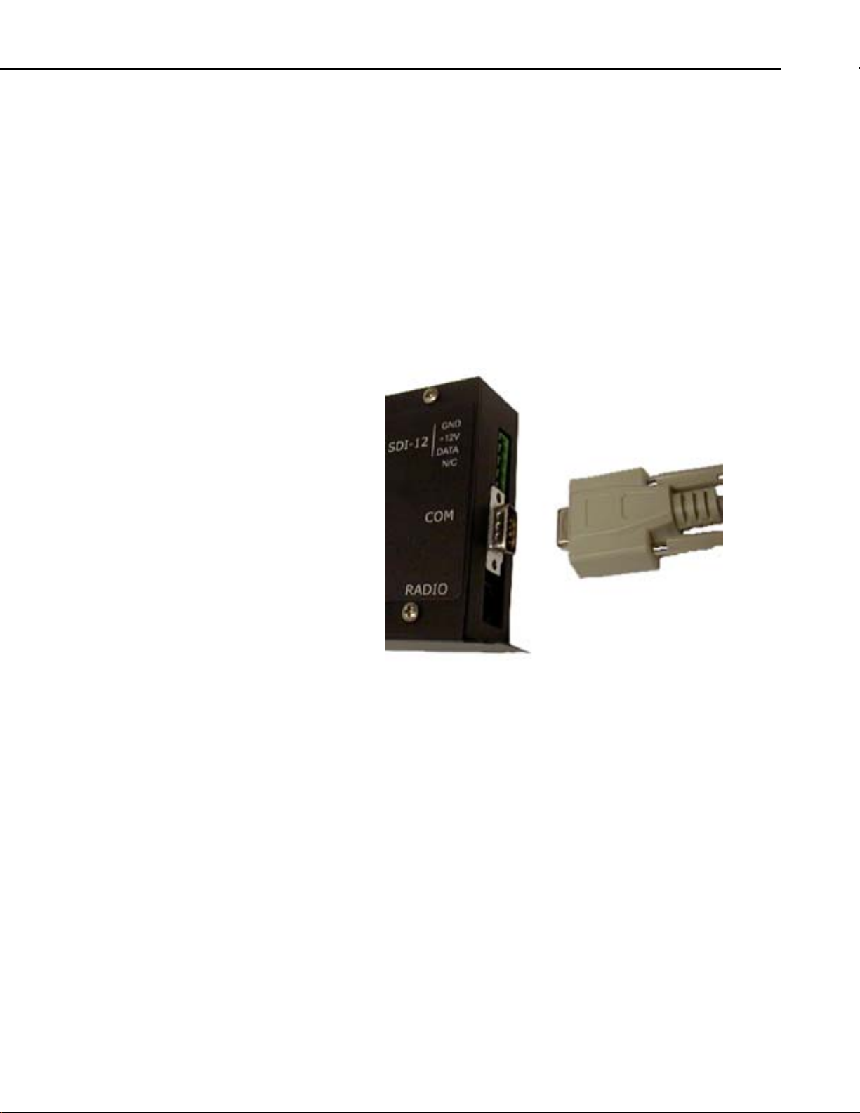
1.3 RS-232C Terminal Interface
This connection provides an interface from the Vosponder to a computer. The
connection is made using a 9-pin female to 9-pin female null modem cable, as
shown in Figure 1-3.
This allows a user to configure various operational parameters, upload the
voice image file, view existing settings, and view incoming DTMF tones and
SDI-12 commands. The terminal interface is time-out protected, which means
that it will return the Vosponder to its runtime mode after 60 seconds of
inactivity on the terminal keyboard. This is done to prevent inadvertent system
lock-ups. A schematic of the connector can be found in Appendix B, Figure
B-3.
Section 1. Hardware
FIGURE 1-3. J5, RS-232C Terminal Interface
1-3
Page 12

Section 1. Hardware
This is a blank page.
1-4
Page 13

Section 2. Programming the Datalogger
1. Hardware connections to the datalogger and radio (Section 1)
► 2. Programming the datalogger to output the data values to the
Vosponder (Section 2)
3. Developing a voice image file for the Vosponder (Section 3)
4. Setup and testing of the Vosponder (Section 4)
The datalogger should now be connected to the Vosponder via the SDI-12
interface cable and the Voponder should be connected to the radio via the radio
interface cable.
The second step is to develop or modify an existing datalogger program so that
it includes the instructions that will output the desired data values to the
Vosponder. There are three commands that will be described in this section,
each has a different purpose and all can be used in a datalogger program to
maximize the benefits of the Vosponder. These three commands are:
• Send Data Command (XD); transfers the current data values to the
Vosponder so that they can be associated with specified text strings and
then broadcast.
• Speak Text Command (X T) ; sends text strings to the Vosponder to be
broadcast. This command is useful for creating customized alarm
messages.
• Speak Now Command (XS); causes the most recent data values and their
associated text strings that are stored on the Vosponder to be broadcast
immediately. This command is useful for causing voice alarms to be
issued based on events or conditions.
This manual assumes that the user is familiar with writing programs for
Campbell Scientific dataloggers. This manual in no wa y covers all of the
possible programming instructions and program configurations that could be
used to initiate a voice message broadcast from a datalogger.
Several examples are provided to give the user the basic programming
concepts and program structure necessary to send data, text, or commands from
the datalogger through the Vosponder and over the radio link. If you just want
to get a quick idea of how the Vosponder works, then create a program in
EDLOG that is exactly like the one shown in Example 2-1 and then move on to
Section 3. Otherwise, develop your own datalogger program using any or all
of the instructions demonstrated in this section and then move on to Section 3.
IMPORTANT: The data values that you want the Vosponder to verbalize
must be located in consecutive input locations in the datalogger program.
2-1
Page 14

Section 2. Programming the Datalogger
2.1 Send Data Command
The following example depicts an EDLOG program for a CSI datalogger that
sends the battery voltage, internal datalogger temperature, and the time to the
Vosponder. The Vosponder is assumed to have been set up with an SDI-12
address of 1 and the SDI-12 data line (white wire) to be wired into the
dataloggers control port 1 (C1).
Example 2-1. Program to send three data values to the Vosponder
*Table 1 Program
01: 10 Execution Interval(seconds)
1: Batt Voltage (P10)
1: 1 Loc [ BatVolts ]
2: Internal Temperature (P17)
1: 2 Loc [ IntTemp ]
3: Time (P18)
1: 1 Minutes into current day (maximum 1440)
2: 0 Mod/By
3: 3 Loc [ Time ]
4: SDI-12 Recorder (P105)
1: 1 SDI-12 Address; Vosponder SDI-12 Address
2: 0 Start Measurement (aM0!)
3: 1 Port ;Control Port C1
4: 1 Loc [ BatVolts ] ;Location of the first data point to be sent
5: 1.0 Mult
6: 0.0 Offset
5: Extended Parameters 4 Digit (P68)
1: 88 Option ;Send “X” to indicate an extended command
2: 68 Option ;Send “D” to indicate that data is to follow
3: 128 Option ;Send the first data value (BatVolts)
4: 128 Option ;Send the second data value (IntTemp)
5: 128 Option ;Send the third data value (Time)
6: 0000 Option ;End of command marker
7: 0000 Option
8: 0000 Option
The above program will issue the SDI-12 command “1XD” then transfer three
data values to the Vosponder. This will take place every execution interval
(i.e., ten seconds in our example).
IMPORTANT:
2-2
• It is critical that all of the data values you will be sending to the Vosponder
are in consecutive input locations.
• The position that follows the last 128 must have “0000” (zeros) in it. If
the eighth position in the P68 is filled with a 128, then you will need to
issue another P68 with just “0000” (zeros) in it.
Page 15

Section 2. Programming the Datalogger
Additional data values (input locations) can be sent to the Vosponder by adding
P68 commands consecutively, as shown in Example 2-3. The number of data
value characters is limited to no more than 102. For example, you could
transmit as many as 17 data values that each had 6 characters. When
calculating the total number of characters, the positive and negative sign (+/-)
and the decimal point are included.
Example 2-2. Character Count
Input Locations: Possible Value Characters
1. BatVolts +10.51 6
2. IntTemp -15.6126 8
3. Time +1012 5
------------------------------------------------------------------------------Total Characters 19
Example 2-3 shows only the program section that would send the data values
from the datalogger to the Vosponder. The measurement instructions for all of
the data values would need to be added prior to this section. The code shown
will issue the SDI-12 command “1XD” then transfer nine data values to the
Vosponder.
Example 2-3. Program to send seven data values to the Vosponder
4: SDI-12 Recorder (P105)
1: 1 SDI-12 Address
2: 0 Start Measurement (aM0!)
3: 1 Port ;C1
4: 1 Loc [ BatVolts ] ;Location of the first data point to be sent
5: 1.0 Mult
6: 0.0 Offset
5: Extended Parameters 4 Digit (P68)
1: 88 Option ;Send “X” to indicate an extended command
2: 68 Option ;Send “D” to indicate that data is to follow
3: 128 Option ;Send the first data value (BatVolts)
4: 128 Option ;Send the second data value (IntTemp)
5: 128 Option ;Send the third data value (Time)
6: 128 Option ;Send the fourth data value (AirTemp_C)
7: 128 Option ;Send the fifth data value (Rel_Humid)
8: 128 Option ;Send the sixth data value (Wind_Spd)
6: Extended Parameters 4 Digit (P68)
1: 128 Option ;Send the seventh data value (Wind Dir)
2: 128 Option ;Send the eighth data value (Solar_Rad)
3: 128 Option ;Send the ninth data value (Baro_Pres)
4: 0000 Option ;End of command marker
5: 0000 Option
6: 0000 Option
7: 0000 Option
8: 0000 Option
IMPORTANT: The position that follows the last 128 must have “0000”
(zeros) in it. If the eighth position in the P68 is filled with a 128, then you will
need to issue another P68 with just “0000” (zeros) in it.
2-3
Page 16

Section 2. Programming the Datalogger
2.2 Speak Text Command
The speak text command can be used for alarming conditions. Example 2-4 is
a program that shows how the speak text command could be formatted.
Example 2-4. Program to send text string to the Vosponder
*Table 1 Program
01: 10 Execution Interval(seconds)
1: Batt Voltage (P10)
1: 1 Loc [ BatVolts ]
;IF BATTERY VOLTAGE IS LESS THA N 1 0.5 VOLTS…
1: If (X<=>F) (P89)
1: 1 X Loc [BatVolts ]
2: 4 <
3: 10.5 F
4: 30 Then Do
;EVERY FIVE MINUTES
2: If time is (P92)
1: 0 Minutes (Seconds --) into a
2: 5 Interval (same units as above)
3: 30 Then Do
;INITIATE AN ALARM MESSAGE OVER THE RADIO LINK
11: SDI-12 Recorder (P105)
1: 1 SDI-12 Address
2: 0 Start Measurement (aM0!)
3: 1 Port ;Control Port C1
4: 1 Loc [ BatVolts ] ;Starting location, but ignored
5: 1.0 Mult ;in “Speak Text” mode
6: 0.0 Offset
12: Extended Parameters 4 Digit (P68)
1: 88 Option ;Send “X” to indicate an extended command
2: 84 Option ;Send “T”, Speak Text Command
3: 32 Option ;Send a Space Character
4: 83 Option ;Send “S”
5: 73 Option ;Send “I”
6: 84 Option ;Send “T”
7: 69 Option ;Send “E”
8: 32 Option ;Send a Space Character
13: Extended Parameters 4 Digit (P68)
1: 51 Option ;Send “3”
2: 49 Option ;Send “1”
3: 32 Option ;Send a Space Character
4: 76 Option ;Send “L”
5: 79 Option ;Send “o”
6: 87 Option ;Send “w”
7: 32 Option ;Send a Space Character
8: 66 Option ;Send “B”
2-4
Page 17

Section 2. Programming the Datalogger
14: Extended Parameters 4 Digit (P68)
1: 65 Option ;Send “A”
2: 84 Option ;Send “T”
3: 84 Option ;Send “T”
4: 69 Option ;Send “E”
5: 82 Option ;Send “R”
6: 32 Option ;Send a Space Charter
7: 69 Option ;Send “E”
8: 0000 Option ;End of command marker
6: End (P95)
7: End (P95)
The program in Example 2-4 will issue the SDI-12 command “1XT” which
causes the Vosponder to say “Site 31 Low Battery” every five minutes, when
the battery voltage measurement is less than 10.5 volts. This message will
continue to be sent through the Vosponder every time the instruction executes
as long as the condition remains true.
The speak text command can be useful for creating custom alarm conditions
and specific text beyond the standard data strings. The speak text instructions
should typically be put after a conditional “IF” statement (i.e., P89 IF X=F) or
be based on the condition of a flag or port. This allows the user to maintain
control of how often the message is broadcast. Putting the voice text section of
the code inside a P92 (IF Time) instruction or a counter loop, can also be used
to limit the number of times a message is broadcast. This keeps the system
from continuously broadcasting and tying up the radio link and draining the
power supply.
2.2.1 ASCII Table
ASCII value
& character
32 (space)
33 !
34 "
35 #
36 $
37 %
38 &
39 '
40 (
41 )
42 *
43 +
ASCII value
& character
44 ,
45 46 .
47 /
48 0
49 1
50 2
51 3
52 4
53 5
54 6
55 7
This table is used to determine the ASCII value for the characters that will be
spoken. The corresponding numbers are entered into the P68 instruction as
shown in Examples 2-1 and 2-3. USE ONLY UPPER CASE CHARACTERS;
lower case characters WILL NOT BE RECOGNIZED BY THE
VOSPONDER.
ASCII value
& character
56 8
57 9
58 :
59 ;
60 <
61 =
62 >
63 ?
64 @
65 A
66 B
67 C
ASCII value
& character
68 D
69 E
70 F
71 G
72 H
73 I
74 J
75 K
76 L
77 M
78 N
79 O
ASCII value
& character
79 O
80 P
81 Q
82 R
83 S
84 T
85 U
86 V
87 W
88 X
90 Y
91 Z
ASCII value
& character
92 [
93 \
94 ]
95 ^
96 _
97 `
98 a
99 b
100 c
101 d
102 e
103 f
ASCII value
& character
104 g
105 h
106 i
107 j
108 k
109 l
110 m
111 n
112 o
113 p
114 q
115 r
ASCII value
& character
116 s
117 t
118 u
119 v
120 w
121 x
122 y
123 z
124 {
125 |
126 }
127 ~
2-5
Page 18

Section 2. Programming the Datalogger
2.3 Speak Now Command
The speak now command can be used for outputting a voice data string upon
conditions determined by the datalogger. This command will do nothing
unless a speak data or speak text command has been implemented in the
program. Example 2-5 is a program that shows how the speak now command
could be formatted. The conditions for using the speak now command might
be a timed interval (i.e., P92 IF Time), a conditional “IF” statement (i.e., P89
IF X=F), or a flag or port condition. This allows the user to maintain control of
how often the message is broadcast. This keeps the system from continuously
broadcasting and tying up the radio link and draining the power supply.
If you were to create a dat alogger program using the instructions shown in
Example 2-1 followed by the instructions shown in Example 2-5, the
Vosponder would speak the three data values (battery voltage, datalogger
temperature, and time) every 60 minutes.
Example 2-5. Program to initiate immediate broadcast of the most recent
data values
;AT THE START OF EVERY HOUR
2: If time is (P92)
1: 0 Minutes (Seconds --) into a
2: 60 Interval (same units as above)
3: 30 Then Do
;SEND DATA VALUES OVER VOICE RADIO LINK
3: SDI-12 Recorder (P105)
1: 1 SDI-12 Address
2: 0 Start Measurement (aM0!)
3: 1 Port ; Control Port 1
4: 1 Loc [ BatVolts ] ;Starting location, but ignored
5: 1.0 Mult ;in “Speak Now” mode
6: 0.0 Offset
4: Extended Parameters 4 Digit (P68)
1: 88 Option ;Send “X” to indicate an extended command
2: 83 Option ;Send “S”, Speak Now Command
3: 0000 Option ;End of command marker
4: 0000 Option
5: 0000 Option
6: 0000 Option
7: 0000 Option
8: 0000 Option
7: End (P95)
The program in Example 2-5 will issue the SDI-12 command “1XS” and will
cause the Vosponder to speak its programmed voice data string every 60
minutes. Anyone with a radio set to the same frequency as the remote site
would be able to hear the broadcast message.
2-6
Appendix F is an example of a program that uses all three SDI-12 commands.
Page 19

Section 3. Developing the Voice Image File
1. Hardware connections to the datalogg er and radio (Section 1)
2. Programming the datalogger to output the data values to the
Vosponder (Section 2)
► 3. Developing a voice image file for the Vosponder (Section 3)
4. Setup a nd testing of the Vosponder (Section 4)
After completing Section 2, you should now have the datalogger programmed
to send data values to the Vosponder. Step 3 is used to create a voice image
file to upload to the Vosponder.
3.1 Purpose of the Voice Image
The Vosponder uses an image string to associate the appropriate text with the
data values that it receives from a datalogger. The voice image file contains
the following information:
• How many data values will be sent from the datalogger.
• The text to be spoken prior to each data value.
• How to speak the numerals.
• Whether to speak the decimal point or not.
• How many digits to the right of the decimal point to speak.
• The text to be spoken following each data value.
An example of a single data value that contains the numeral +76.457 could
sound like t hi s :
“The curre nt temperature is seventy six point four degre es.”
Or:
“Tank number three is +76.46 percent full.”
3.2 Creating a Voice Image File
There are two ways to create a voice image file.
1. Use the Voice Image Development Software that is included with the
Vosponder.
3-1
Page 20

Section 3. Developing the Voice Image File
2. Manually create the text strings and associate the data values. This can be
done using a ny text editor. A user must be very care ful to make sure that
the format of the voice image text string is correct. If it isn’t, then the
Vosponder may react adversely when the file is uploaded to it and may
require a compete reset. Appendix E offers information on the anatomy of
a voice image file so that users can manually create or modify the voice
image file should they choose to do so. We only recommend that this be
done if the software is not available.
The following section of the manual only covers the methods used to create a
voice image file using the development software. The best way to start this
process is to identify the data values (input locations) you would like to include
in your voice data string, and what the message will say. Using Example 2-1
from Section 2, the input locations that we have programmed the datalogger to
send to the Vosponder are as follows:
Data value 1 = Battery Voltage (BatVolts)
Data value 2 = Logger Temperature (IntTemp)
Data value 3 = Minutes into the Day (Time)
IMPORTANT: The data values that you want to verbalize must be located in
consecutive input locations. If they are not, then the data value (input location)
will not be associated with the correct text string.
Once the data value list is assembled, you should then write out your id eal
sentence structure (preferably on paper). An example might look like this:
For Beaver Creek Station 31.
The current battery volt age is “Value1” volts.
The dataloggers internal temperature is “Value2” degrees C.
The time is “Value3”minutes into the day.
The Vosponder has the ability to verbalize a wide range of text, which allows
the voice message to be completely customized to a user’s requirements.
When developing voice text strings there are several things the user should be
aware of, these are:
¾ Numbers can be entered as either 123, which will be spoken as one
hundred twenty-three or can be entered with spaces between each number,
such as 1 2 3, which will be spoken as one, two, three.
¾ Common abbreviations such as St., Mt., Rd., Ave. can be used. However,
the abbreviation must be followed with a period. Not all abbreviations are
supported, so you may have to spell out the word completely if the
abbreviation is not spoken correctly.
¾ Individual letters that are consecutive will be spoken as letters as long as
no vowels are included in the string. However, if a vowel is included in
the string, the Vosponder will attempt to speak the text string as a word.
For example: “DO” would be pronounced as “do” instead of “D” “O”. To
use this abbreviation for dissolved oxygen you would put a space or a
period between the D and the O so that the Vosponder will understand that
the letters are to be spoken separately. “pH” on the other hand would be
spoken as “P” “H” because there is no vowel in the text string. It is still
often a good practice to put a space or period between the characters, as
3-2
Page 21

Section 3. Developing the Voice Image File
this causes a small pause between the letters and makes the verbalization
clearer.
¾ Punctuation and other characters are verbalized as follows:
• Period, question mark, exclamation mark, and a comma can be used to
create pauses between sentences, words, or letters. Adding any of
these characters consecutively will create a longer pause. Each of
these characters adds a little less than a one-half-second delay (i.e., 12
periods will cause a 5-second delay)
• # is spoken as “number” (i.e., Station # 5 would be spoken as
“Station number five”)
• $ is spoken as “dollar”
• * is spoken as “star”
• & is spoken as “and”
• % is spoken as “percent”
• = is spoken as “equals”
• + is spoken as “plus”
• > is spoken as “greater than”
• < is spoken as “less than”
¾ The Vosponder can reproduce most words. However, if you find a word
that is not spoken correctly, then spell the word phonetically. The
Vosponder will then verbalize it correctly. For example, if the name of the
site location were “Duchesne River” (pronounced Do Shane River), the
Vosponder would not pronounce it correctly using that spelling. However,
by spelling the site name as “Dewshane River” or “Do Shane River” the
Vosponder would now pronounce the site name correctly.
¾ Foreign languages are not supported at this time. However, many words
may be spoken by using a phonetic spelling. For example, “the water
level” in Spanish would be spelled “el nivel del agua”. The Vosponder
could speak this phrase by entering text as “el neevel del augwah”.
However, the data value will still be spoken only in English. Exception
and foreign language dictionaries for the Vosponder may be available.
Contact a technical support representative at (435) 755-0300 or e-mail
your inquiry to support@dacomtechnologies.com.
3.3 Using the Voice Image Development Software
Install the Image Development Software program on your computer. You
should see the image maker shortcut icon appear on your desktop after the
program has been installed. Double-click on the image maker icon to open the
program.
The Image Development program is a basic Java Script that will open in any
browser such as Internet Explorer. The program has four basic options; these
are denoted by an icon in the upper left section of the screen.
Icon Text Purpose
Sheet of Paper New Creates a new voice image file
Folder Open Opens an existing voice image file for editing
Diskette Save Saves the current voice image file as a .txt file
Plus Sign Add Phrase Add a sentence to the open voice image file
3-3
Page 22

Section 3. Developing the Voice Image File
3.3.1 Building the Voice Image File
Begin by selecting the “New” icon (picture of a sheet of paper). This will open
a new file and the “Add Phrase” window will appear. In this window you enter
the text you want spoken before and after the data values. You can also select
settings for how the data will be spoken. This is done by selecting the box to
the right of the option. If you choose to have the decimal spoken, then you can
also set how many decimal points you want spoken. When you are done select
“Add”. This will save the first text string, clear the text boxes, and increment
to the second data value.
3-4
NOTE
The value corresponds to the order of the input locations that will
be sent from the datalogger to the Vosponder. In our previous
programming Example 2-1 the input locations that we
programmed the datalogger to send to the Vosponder were in the
order of battery voltage, datalogger temperature, and time. The
battery voltage would be Value1, datalogger temperature would
be Value2, and time would be Value3.
Using our example data values we would enter the following text. In the
Beginning field type in “Beaver Creek Site 31..Batter y voltage is" then move to
the End field and type “Volts..”.
We would then enter the two other text strings in a similar manner. Note that
we have added two periods after the end of each sentence. This helps to clearly
separate each sentence from each other. After you have added your final text
string, select “Close” from the “Add Phrase” window. You see the main
screen with a line of text for each data value you want to have spoken.
Page 23

When you have finished creating the voice image file, it can be saved by
selecting the “Save” icon located on the upper left side of the screen (picture of
a disk). You should give each image a unique name and save it to floppy disk
or to your computer’s hard drive. The voice image file will need to be
uploaded to the Vosponder, so saving it someplace that is easy to find is a good
idea.
Close out of the Voice Image Development Software simply by closing your
browser.
3.3.2 Editing the Voice Image File
Section 3. Developing the Voice Image File
If you need to make changes to an existing voice i mage file, you can do so by
first selecting the “Open” icon from the main screen (picture of a folder).
You can now add, delete, edit, or move a phrase.
Add a Phrase
To add phrases select the “Add Phrase” icon from the upper left side of the
screen (picture of a plus sign). The “Add Phrase” screen will appear and you
can make modifications as desired. Once all the modifications are completed
select “Close”.
Edit a Phrase
To edit a phrase select it by double-clicking on the phrase to be edited. The
“Add a Phrase” screen will appear with the text and setting for the current
phrase. Make any modifications and then select “Close”.
3-5
Page 24

Section 3. Developing the Voice Image File
Delete a Phrase
To delete a phrase select the “x” to the right of the phrase you want to delete.
You will be asked to confirm the deletion process. If you answer “OK”, the
phrase will be deleted.
Move a Phrase
To move a phrase so that it is spoken sooner when the message is broadcast,
select the UP arrow symbol located to the left of the phrase. To move a phrase
so that it is spoken later, select the DOWN arrow symbol located to the left of
the phrase. When the arrow is selected, the phrase will move up or down one
location in the direction of the selected arrow. Note, this has no effect on the
order that the data values are sent from the datalogger to the Vosponder. It
only affects the order in which the Vosponder broadcasts the text phrases
associated with each data value.
After making any changes to the current voice image file, select the “Save”
icon (picture of a diskette).
3-6
Page 25

Section 4. Vosponder Configuration and Programming
1. Hardware connections to the datalogg er and radio (Section 1)
2. Programming the datalogger to output the data values to the
Vosponder (Section 2)
3. Developing a voice image file for the Vosponder (Section 3)
► 4. Setup and testing of the Vosponder (Section 4)
4.1 Communicating with the Vosponder
The final step is to configure the Vosponder and upload the voice image file
that you created in Section 3. Connect the Vosponder to a computer using a
null modem cable. (See Section 1, Figure 1-3.) The computer will need to be
running a terminal program such as HyperTerminal® or Procom®. The
Vosponder will also need to be powered. If you have the Vosponder connected
to the datalogger with the SDI-12 cable and the datalogger’s power supply is
on, then the Vosponder will have power. Otherwise, you will need to run a
12 VDC power connection to +12 V and GND inputs on the Vosponder’s
SDI-12 terminal.
Open HyperTerminal or your terminal program and set up a new file. The
terminal communications settings must to be set as follo ws:
Baud Rate 2400
Data Bits 8
Parity None
Stop Bit 1
Flow Control Xon / Xoff
ASCII Line Delay 15 milliseconds or greater
ASCII Character Delay 20 milliseconds or greater
4-1
Page 26

Section 4. Vosponder Configuration and Programming
The screen replicas depicted in this section will be those displayed when using
Microsoft® HyperTerminal® Version 5.1 running under Windows® XP.
Other terminal emulation programs may have some slight differences, but
should function in a similar manner.
Once the terminal program is running and the configuration settings have been
saved, you should see a blank terminal screen. Press any key to bring up the
Vosponder main menu prompt. At this point the Vosponder switches from
runtime mode to terminal command mode.
DACOM Technologies, Inc. 435-755-0300
www.dacomtechnologies.com
13DACOMTEC VSP3_010*034C*EU2025
(R)eset
(V)iew
(E)dit
(S)peak
(A)larm
(T)alk
(U)pload
(X)parent
(ESC)
M:>
FIGURE 4-1. Terminal Command Mode - Main Menu Prompt
4.2 Entering Commands
Upon displaying the main menu prompt (M:>), the Vosponder is ready to
accept commands. Note that, due to the precedence of the internal processes
the terminal may require several keystrokes before it responds with the initial
main menu prompt. The terminal cannot respond while transmitting text or
receiving SDI-12 data and does not store keystrokes while busy.
All command entries must be in UPPER CASE letters. You may want to
turn the keyboard “Caps Lock” on while working with the Vosponder in
terminal command mode. Lower case letters are ignored, and thus you may try
to enter commands using lower case letters and think the Vosponder is not
working properly.
Menu prompts that are displayed will indicate the current menu level and
command. If a colon (“:”) is present, it indicates that you are at the top level of
the current menu.
M:> denotes that you are in the Main menu at the top level
4-2
When the colon (“:”) is not present then it indicates that you are in the lowest
possible level of a menu. For example:
Vi> denotes that you are in the View | Image menu, and that
there are no other menus below this level. You still have
options to choose from but you are at the end of the menu
tree.
Page 27

Section 4. Vosponder Configuration and Programming
See Appendix D for a complete diagram of the Vosponder menu tree.
At any prompt, entry of an <ESC> will abort the command and/or move back
one menu level. If at the main menu, <ESC> will return the Vosponder to its
runtime mode .
At each prompt a 10-second timeout feature is provided that will abort the
command and/or move back one menu level if no activity on the keyboard
happens in this time period. Ultimately the unit will return to the runtime
mode from any menu level or command prompt if there is 60 seconds of
inactivity on the keyboard.
From this po int in the manual you can continue on through Secti on 4.2 and
familiarize yourself with each of the menus and commands. Or you can skip to
Section 4.3 and start setting up the Vosponder while using this section as a
reference as you work your way through the setup process shown in Section
4.3.
4.2.1 Main Menu Commands
A description of each main menu command follows. Letters that are bolded on
the screen shots are examples of what the user would enter to progress through
the Vosponder’s menu tree.
R - Reset System. This command executes a cold reset. It restores all
parameters to the factory defaults including the SDI-12 mode, voice image file,
and test data values. A confirmation of “Y” is required to complete the reset
command. You must enter a “Y” and then press <ENTER> in order for this
command to take affect. When the “Reset” is complete the Vosponder will
return to the main menu M:>.
DACOM Technologies, Inc. 435-755-0300
www.dacomtechnologies.com
13DACOMTEC VSP3_010*034C*EU2025
M:>R
M:>!! *CONFIRM RESET* !! (Y)
V- View. Allows the user to see the following parameters (for more details
see Section 4.2.1):
• DTMF digits received
• Voice image ID
• Two-way radio transmit hang time, delay, and channel busy sense se ttings
• Data last transferred to the Vosponder from the datalogger
• SDI-12 address and DTMF code assignments
4-3
Page 28

Section 4. Vosponder Configuration and Programming
M:>V
(D)TMF
(I)mage
(T)X
(A)ddr
Data (V)alues
(ESC)
V:>
E - Edit. Allows user to edit the following parameters (for more details see
Section 4.2.2):
• DTMF Code
• SDI-12 Address
• SDI-12 Mode
• Transmit Settings
M:>E
(D)TMF Code
(S)DI-12 Adr
SDI-12 (M)ode
(T)x
(ESC)
E:>
S - Speak Now. Speaks the most recent data values using the current
voice image file. If a radio is attached to the Vosponder and a handset is
turned on and listening on the same frequency as remote sites radio, the user
will hear the voice message.
M:>S
S:>
A - Speak Alarm. Speaks the currently loaded alarm text. (Not used in
this version.)
T - Talk Keyed Entry. This allows the user to enter a “pass-through”
mode that sends text entered from the keyboard directly to the Vosponder’s
speech module. In the example screen below, the user typed in “THIS IS A
TEST” then pressed <ENTER>. The Vosponder would immediately broadcast
this message over the radio link.
4-4
If you have any question about how the Vosponder will speak a word or a
symbol, this feature will allow you to test those text strings before you program
them into a voice image file.
M:>T
T:>THIS IS A TEST
Page 29

Section 4. Vosponder Configuration and Programming
U - Upload. Transfers a prepared voice image file to the Vosponder from
a computer. The image must be properly formatted for the intended function.
(See Section 3 for details on creating the voice image file and Section 4.3 for
details about uploading a voice image file to the Vosponder.)
M:>U
U:>***
X – Transparent. Enters SDI-12 transparent mode. (Used only in master
mode.)
ESC. Entering <ESC> exits the system command mode and puts the
Vosponder back into the runtime mode with all changes saved.
4.2.2 View Menu Commands
The view menu as shown in Figure 4-3 allows the user to see the DTMF digits
received, the voice image ID, the two-way radio transmit hang time, delay and
channel busy sense settings, the data last transferred to the Vosponder from the
datalogger, and the assigned SDI-12 address and DTMF code.
V:>
(D)TMF
(I)mage
(T)x
(A)ddr
Data (V)alues
(ESC)
V:>
FIGURE 4-3. Terminal Command Mode – View Menu Prompt
(With Help)
D - DTMF. This command allows the user to view received DTMF digits
on the computer terminal. DTMF digits are generated by pressing the numeric
keypad on a radio handset. Each numeric character on the keypad creates a
specific tone.
After entering “V” then “D” the Vosponder will reply with Bye! It is now in a
listening mode and will echo back to the PC terminal any DTMF keys that it
receives from a radio handset. Press the radio handset’s “Push-to-talk” key and
enter any pattern of numbers from the keypad. You will see each number that
you press appear on the computer terminal screen. In the example screen
below the user has pressed each of the numeric keys 9-1 on the handset. To
exit from this mode, press any key on the computer keyboard.
This mode is useful for testing the communication link between the handset
and the Vosponder, and to make sure that DTMF entries on the handset are
correctly received by the remote site.
4-5
Page 30

Section 4. Vosponder Configuration and Programming
V:>D
VD>Bye!
9 8 7 6 5 4 3 2 1
I - Image. This command allows the user to view the current voice image
file that is loaded on the Vosponder. Entering a “V” will display the voice
image text string. (M)aster is only used with the master mode option and does
not apply to CSI datalogger users with the Vosponder in slave mode. For more
information on the anatomy of a voice image file, see Appendix E.
V:>I
VI>
(V)oice/(M)aster
VI>V0301The Battery is|NY2volts.|02The temperature
is|NY1Degrees C.|03 and it's|NN0minutes into the
day.|{^9*^1*^1*. Alarm!}
T – X (Transmit). This command allows the user to view the current
two-way radio transmit hang time and delay and channel busy sense settings.
The example scree n shows the Vosponder’s default settings for these
parameters. Only in special cases should a user ever need to modify these
settings. Changes should never be made to these settings without first
consulting a technical support representative. The only exception to this is if
the user fully understands the ramifications of making changes to these
settings.
V:>T
VT>TX Int:0 TX Dly:500 TX Hang:750 RCOS TX:N
A - Address. This command allows the user to view the current SDI-12
Mode, the assigned SDI-12 address, and the assigned DTMF code. In the
example screen below the Vosponder has been set to the SDI-12 “S” (slave)
mode, has been assigned the number “1” as the SDI-12 address, and has a
DTMF code of “123”.
V:>A
VA>SDIMode:S SDIADR:1 DTMF:123
V - Data Values. This command allows the user to view the most recent
string of data values received by the Vosponder from the datalogger. The data
values shown in the example screen below are test values that come preloaded
on the Vosponder. If the Vosponder has never received data from a datalogger,
or has been reset, these are the data values that will be used when the (S)peak
command is issued from the main menu. Once the Vosponder has received a
data string from the datalogger, the numbers on this screen would reflect the
values that the Vosponder is receiving.
This feature is useful for checking the communication link between the
datalogger and the Vosponder. It allows the user to make sure that the
Vosponder is getting data values in the expected order from the datalogger. If
4-6
Page 31

not, then the user will need to modify either the datalogger program or the
Vosponder voice image file.
V:>
VV>
VV>+12.491+20.762+748.00
4.2.3 Edit Menu Commands
The edit menu as shown in Figure 4-4 allows the user to edit the DTMF code,
SDI-12 address, SDI-12 mode, and transmit settings.
M:>E
(D)TMF Code
(S)DI-12 Adr
SDI-12 (M)ode
(T)x
(ESC)
E:>
FIGURE 4-4. Terminal Command Mode – Edit Menu Prompt
Section 4. Vosponder Configuration and Programming
(With Help)
D – DTMF. This is the DTMF code that the Vosponder responds to. The
DTMF code can be from 1 to 5 digits and can be any combination of valid
DTMF digits 0 – 9,* and #. Characters are not echoed on the PC terminal until
an <ENTER> key is pressed. It is recommended that DTMF codes be kept to 2
or 3 digits. Longer DTMF codes can be more susceptible to a user
inadverte ntly hitting an invalid key and thus ha ving to re-k ey the DTMF code
over and over until it is exactly correct.
In the example screen below the user has entered the DTMF code 123 and the
pressed <ENTER>. The user can now cause the Vosponder to send a voice
message by pressing the numbers 1 2 3 on the radio hand sets keypad.
E:>D
ED>
Enter DTMF Code
ED>123
S – SDI-12 Address. This is the SDI-12 bus device address. This can
be any valid SDI-12 address 0 – 9. The Vosponder comes with a default
SDI-12 address of “0”. See Appendix A for more information about the
SDI-12 protocol.
E:>S
ES>
Enter SDI-12 Slave Ad
ES>1
4-7
Page 32

Section 4. Vosponder Configuration and Programming
M – SDI-12 Mode. The SDI-12 mode can be set to master or slave .
The unit defaults to “Slave” mode. In the slave mode the unit emulates a
sensor. In the master mode the unit emulates a datalogger. For CSI datalogger
users, it is recommended that the Vosponder be in the “Slave” mode. See
Appendix A for more information on why and how to use the “Master” mode.
E:>M
EM>
(M)aster
(S)lave
(ESC)
EM>S
T – x (Transmit). The transmit settings below should not require
modification under normal conditions. This command allows the user to
modify radio transmit interval, delay, hang time and channel busy sense
settings.
E:>T
E:>
ET>
ET>TX Int:0 TX Dly:500 TX Hang:700 RCOS TX:N
TX Int:0
ET>TX Dly:500
ET>TX Hang:700
TX on COS Y/I/N/D:N
ET>
• The Transmit Interval is set in seconds from 0 to 65535 seconds. {default
= 0}
o This value is used to determine the time between transmission of the
last data stored in the unit from the datalogger in the slave mode or the
interval between issuing a sensor query and transmitting the data
retrieved from the sensor(s).
o The interval timer (not the time value) is reset upon DTMF or RCOS
query.
o The keyboard characters entered here are not echoed to the PC
terminal until an <ENTER> key has been pressed.
• The Transmit Delay is set in milliseconds from 0 to 65535. {default =
500}
o This parameter determines the delay time before the Vosponder starts
speaking after it keys the transmitter push-to-talk.
o The keyboard characters entered here are not echoed to the PC
terminal until an <ENTER> key has been pressed.
4-8
Page 33

Section 4. Vosponder Configuration and Programming
• The Transmit Hang Time is set in milliseconds from 0 to 65535. {default
= 539}
o Hang time determines the duration that the Vosponder leaves the
transmitter keyed after speaking.
o The keyboard characters entered here are not echoed to the PC
terminal until an <ENTER> key has been pressed.
• The Busy Sense or COS sets how the Vosponder responds to a channel
busy signal on pin 8 of the radio connector (J6 in Figure 1-1). {default =
N}
o No; any input on this pin is ignored.
o Yes; the Vosponder will speak the voice image when there is a
voltage (3 – 13 Volts) applied to the pin.
o Inverted; the Vosponder responds to the pin if a voltage is absent
This means that if power to the radio is lost or the radio is disconnected,
the Vosponder will be stuck in the speak mode. Caution: This option
should not be used under most conditio ns, because it will tie up the radio
frequency and drain the power supply very quickly.
.
o If Set to Data, the Vosponder will suspend speech output and
transmitter keying when there is a voltage (3 – 13 Volts) applied to
the pin. This provides a “polite” mode of operation to prevent the unit
from transmitting while the radio channel is busy. This setting can be
used when a single radio or radio frequency is used for both data and
voice transmissions.
o The keyboard characters entered here are not echoed to the PC
terminal until an <ENTER> key has been pressed.
4.2.4 Uploaded Menu (Transfer the Voice Image File)
M:>U
U:>***
From the main menu (M:>) prompt enter a “U” to go to the upload menu then
follow these steps:
1. From the HyperTerminal Transfer drop-down menu select the “Send Text
File” option.
2. Locate and select the voice image file that you have created and want to
transfer onto the Vosponder. Either double-click on the file or select
“Open”.
3. Select “Send” to complete the file transfer to the Vosponder. As the
upload proceeds you will see some characters (!!*<*<) echoed by the
Vosponder for each 64 byte block successfully transferred. If the voice
image file is small, you will only see a few characters. A larger voice
image file will create multiple instances of the characters as it loads. If
you do not get these characters, then you may need to make some changes
to your terminal software settings, see Section 5 - Troubleshooting.
4-9
Page 34

Section 4. Vosponder Configuration and Programming
4.3 Configuring the Vosponder Settings
Information that you will want to have before you start setting up the
Vosponder includes:
1. What SDI-12 address do you want to assign to the Vosponder? The
default is 0. The SDI-12 address should relate to the control port on the
datalogger that you have chosen to wire the SDI-12 interface cable into.
2. What DTMF code (numeric key sequence) do you want to assign to the
Vosponder? The default is 123. Up to five numbers can be used. The
longer the number sequence the more careful you will need to be when
keying in the numbers from the radio handset. Numeric codes of two or
three numbers are recommended.
3. Will you be using the Vosponder in SDI-12 slave or master mode? The
default is slave mode. If you are using the Vosponder with a CSI
datalogger, you will want to be in slave mode.
4.3.1 Steps for Configuration and Testing the Vosponder
1. First view the current settings on the Vosponder by going to the M:>
prompt and entering the letters “V” and then “A”. This will take you to
the Vosponder View | Address screen. From here you can see what the
current settings are for SDI-12 mode, SDI-12 address, and DTMF code. If
the settings do not match what you want, then you will need to go to Step
2, otherwise you can jump to Step 3.
2. To change settings in the Vosponder from the M:> prompt enter “E” this
will take you t o the Edit menu. From here make changes to the variou s
parameters by doing one or all of the following:
a. Change SDI-12 Address - From the E:> enter “S” to and then from
the ES> type in the new SDI-12 address (number from 0-9).
b. Change the DTMF Code – From the E:> enter “D” and then from the
ED> prompt type in the new DTMF code (one to five numbers) and
press <ENTER>
c. Change SDI-12 Mode - From the E:> enter “M” and then from the
EM> type in either “S” (Slave) or “M” (Master) to select the new
mode
3. Upload the voice image file to the Vosponder (see Section 4.2.3).
4. Check the voice image file to make sure that it transferred correctly. After
the voice image file has been transferred, from the M;> prompt enter a
“V”, from the V:> prompt enter an “I”, and then from the “VI” prompt
enter another “V” to view the voice image. Check the text string to make
sure that the text transferred to the Vosponder completely and in the
correct order. For more information about the anatomy of the voice image
file see Appendix E.
The Voice Image Development program adds some additional characters
and numbers that make the image look a little different when it is viewed
4-10
Page 35

Section 4. Vosponder Configuration and Programming
in HyperTerminal. Do not be alarmed by seeing some additional
characters. The image might look something like that shown in
Figure 4-3.
V:>I
VI>V0301Beaver Creek Site 31..The battery voltage
is|NY1volts..|02The dataloggers internal temperature
is|YY1degrees C..|03The time is|NN0minutes into the
day|{^9*^1*^1*. Alarm!}
V:>
FIGURE 4-5. Terminal Command Mode – View | Image | Voice Screen
5. Turn on your radio handset and make sure your remote site radio is
powered. Perform a test on the radio link – from the M:> prompt enter
“S”. The Vosponder should now speak the text with data it has received
from the datalogger. If this works, your program and the voice image are
correct and you have successfully completed the programming process.
6. Initiate a voice message from the datalogger through the Vosponder.
a. Enter <ESC> until you see the word Bye! on the screen.
b. Disconnect the serial cable from the Vosponder COM port.
c. Press the push-to-talk button on your radio handset and while holding
it down, key in the DTMF code and then let off the push-to-talk
button. If this works, you are ready to deploy the remote site.
If you have reached this point in the manual, then congratulations are in order.
You have successfully programmed and configured a Vosponder and
understand the basics of how to get voice data messages. You should now be
able to deploy your datalogger with the Vosponder to a remote site.
After deploying the system it is a good idea to initiate another voice message
test by keying in the DTMF code from your radio handset . Sometimes what
works in the office may have some issues in the field. A clear line of site is
critical for any RF telemetry application. If your remote site does not have this
either directly to your handset or through a repeater networ k, then you will
likely have difficulty getting voic e messages fr om the remote site.
4-11
Page 36

Section 4. Vosponder Configuration and Programming
This is a blank page.
4-12
Page 37

Section 5. Testing and Troubleshooting
5.1 ERROR Codes
When in the terminal mode, error codes may be directed to the screen to aid in
troubleshooting. The following table provides context for the error codes.
TABLE 5-1. Terminal Error Codes
Error Code Cause Corrective Action
2
3
4 Logger data overrun
6 N-V memory ID error Use correct SDI-12 address
7 N-V memory load error Retry image upload
Attempt to use transparent
command in slave mode
SDI-12 transparent mode
timed out
Change to maste r mode
Re-enter transparent mode
Reduce the number of data
values or the number of
characters in the data values to
102 or less.
5.2 Frequently Asked Questions
Problem: I should be hearing voice messages on my radio handset, but
I’m not.
Solution: Check the following:
1. Check the radio handset
a. Wait a minute and try again. Sometimes the Vosponder
can be busy and doesn’t pick up the code on the first try.
It also takes about two program execution intervals
before the datalogger fully runs the program.
b. If you have a second handset, can you talk to the ot her
handset? If not, you may ne ed to change the handset’s
batteries or recharge them. If this doesn’t correct the
problem, then you may need to have t he handset
repaired or replaced.
c. Make sure that the handset i s set to the same frequency
and channel as the radio that is located at the remote
site.
d. Make sure the volume on the handset i s not turned d own
so low that you can’t hear any voice transmission.
e. Make s ure the squelch on the handset is not turned up so
high that you can’t hear transmissions.
5-1
Page 38

Section 5. Testing and Troubleshooting
2. Check the Vosponder
a. Leave the radio system in place. Connect the
Vosponder to the computer using a null modem cable
and initiate communication using a terminal program
such as HyperTerminal. (Refer to Section 4.) At the
main menu prompt (M:>), issue a (S)peak command by
pressing “S”. You should then hear the default text
message coming over your radio.
If this works, then the problem is most likely due to one
of the following:
1. The output from the datalogger program does not
match with the voice image file that is loaded on
the Vosponder. Refer to Sections 2 and 3 to make
sure that the program is written correctly and that
the voice image file matches with the output being
sent from the datalogger.
2. Make sure that the SDI-12 address in the datalogger
program matches the SDI-12 address of the
Vosponder. Refer to Section 3 for details on how
to view the Vosponder’s assigned SDI-12 address.
If this doesn’t work, then the problem is likely with the
radio or radio handset, or a connection problem between
the radio the Vosponder. Check each component if
possible to make sure they are all working properly.
3. Check the datalogger program
a. Make sure that the part of your program where SDI-12
command (i.e., “XD”, “XS”, or “XT”) is issued follows
the correct format. See Section 2. It is critical that there
is a “0” (zero) following the last numeric value in the
last P68 instruction that follows the P105 instruction.
b. You can also connect to the datalogger via a computer
and in LoggerNet and view the Ports/Flags. If your
program is sending more than two values to the
Vosponder, you should see t he port that you have called
in your P105 instruction go high (green dot). If it
doesn’t, then you probably need to modify your
program.
If the datalogger control port goes high, if the Vosponder
responds to the Speak command when directly connected to
a computer, and if the radio link is functional, you should be
able to hear message broadcasts.
5-2
Page 39

Section 5. Testing and Troubleshooting
Problem: My data values are being spoken in the wrong order.
Solution: Open your voice image file in the Vosponder Image
Development Software, and using the UP and DOWN arrow
keys to the left of the phrases, move the phrases into the order
that you want them spoken. Refer to the Section 3.2.
Problem: My data values are being spoken with the wrong text phrases.
Solution: This is caused by the order of the data being sent from the
datalogger to the Vosponder not matching with the order that the
Vosponder voice image file is expecting.
1. Check your datalogger p rogram to make sure that the values
are located in consecutive input locations. Write this order
down or print a copy of the program to have available when
you check the voice image file later. Refer to Section 2.
2. Check the section of your program where the data values are
being transferred to the Vosponder to make sure that you are
sending the same number of data values as you have set the
voice image file up to expect. Refer to Section 2.
3. Open the voice image file using the Vosponder Image
Development Software and check to see that the text strings
are associated with the data values in the order that they are
being sent from the datalogger. If they are not, then make
the necessary modifications to the voice image file. Save
and test. Refer to Section 3.
Problem: The message is coming out but with the default data values
(i.e., 12.777, +27.777,+ 7777) instead of my data values, and the
message gets all messed up after these three values are spoken.
Solution: This is caused by the Vosponder not getting new data val ues
from the datalogger.
1. You will need to connect to the Vosponder through
HyperTerminal and at the M:> issue a “V” and then another
“V”. This will show you the most recent data that the
Vosponder has received from the datalogger. If the values
are still the default values of 12.77, +77.77, 7777 then this
means the datalogger is never passing new data values to the
Vosponder and there is a problem with the datalogger’s
program or the datalogger may not be functioning correctly.
2. Connect to the datalogger using LoggerNet and view the
numeric fields to make sure that new data values are being
displayed there.
3. Check the datalogger program to make sure that the control
port used for the P105 instruction is the same one that you
wired the SDI-12 interface cable from the Vosponder into on
the datalogger.
5-3
Page 40

Section 5. Testing and Troubleshooting
Problem: The Vosponder transmits fine on interval transmissions, or
Solution: There are two possible reasons for this problem.
4. Open the Ports/Flags window and watch to see if the control
port that you have wired the Vosponder’s SDI-12 interface
cable into ever goes hi gh (green dot ). The port must go high
in order for data to be transferred to the Vosponder. If it
doesn’t, then you will need to check your program and/or the
datalogger’s control port to see why the control port is not
working.
when I issue a “Speak Now” command, but it doesn’t respond
when I key in the DTMF code from a handset.
1. You are not keying in the DTMF code that the Vosponder is
expecting.
2. Each radio has small variances that can, in some cases, make
a difference. You will need to test your DTMF decoding.
Both of these solutions can be checked fairly quickly by doing
the following:
1. Connect the Vosponder to a computer using a null modem
cable.
2. Make sure the radio is plugged in to the Vosponder
3. Make sure the Vosponder has at least 10 VDC of power
applied to the +12 VDC SDI-12 terminal.
4. Initiate communication using a terminal program such as
HyperTerminal. (Refer to Section 4.) At the main menu
prompt (M:>), issue a (V)iew command by pressing “V”,
and then enter a “A” to see the current DTMF code. If this
is the same co de you have been keying in, then go to the
next steps.
5. At the V:> prompt, enter a “D”. The screen will do a hard
return and the word Bye! will be displayed. The Vosponder
is now in a listening mode where the corresponding number
associated with any DTMF tones from the radio handset
should be displayed on the PC screen.
6. Hold down the push-to-talk button on the handset and press
various numeric keys on your keypad. Yo u should see the
corresponding number displayed on the PC. If the numbers
are not decoding correctly, or if multiple instances of the
same number are appearing, minor adjustments to the
Vosponder will need to be made. Refer to Appendix C for a
detailed explanation of how to make adjustments to the
Vosponder in order to fix this problem.
5-4
Page 41

Section 5. Testing and Troubleshooting
Problem: The radio doesn’t hang up after a voice message transmission.
Solution: Check the radio interface cable. Make sure that the connection to
the radio and the Vosponder are solid. If the problem still exists,
then try replacing the cable with another one if you have a spare
or can swap one out from another Vosponder that is working.
You may need to repair or replace the cable.
Problem: The Vosponder transmits voice messages great when I set it up
in the office, but when I deploy it to my remo te site it doesn’t
transmit when I key in the DTMF code from a handset, unless
I am close to the site.
Solution: The problem likely has something to do with loss of radio signal
due to the physical or environmental conditions. RF signals
require a clear line of site from the remote to the handset or
through a repeater and then to the handset. If trees, buildings,
mountains, etc. are blocking the path, then the signal may be
reduced or completely lost. Environmental conditions such as
fog and snow can also reduce the range of the RF signal.
A visual check for line of sight may reveal problems that may be
corrected by relocating a remote station or adding a repeater. If
the network appears to have good line of site, then a radio path
study may be in order. T his would revea l any weak links in your
radio network. Things like loose cable connect i ons, damaged
cables, radios, or antennas could be the source of the problem.
Contact a radio specialist who has the right equipment to perform
a radio path study if you don’t have the equipment yourself.
Problem: When the voice message is transmitted, it speaks a bunch of
random letters and will not sto p transmitting.
Solution: This is typically caused by an error that has occurred while
uploading the voice image file to the Vosponder.
1. First check your terminal communication settings in
HyperTerminal or whatever terminal program you are using.
See Section 4.1.
2. Reset the Vosponder by entering an “R” from the M:>
prompt. Then upload the voice image file again. Make sure
to check the voice image file by viewing after you have
uploaded it to the Vosponder. (Refer to Section 4.2.4.)
Important Note: After resetting the Vosponder you will also
need to reset any settings that you had p reviously changed fro m
the default settings, like the SDI-12 address or DTMF code.
Problem: The Vosponder prompt does not appear when HyperTerminal is
opened and a key is pressed on the keyboard.
Solution: This is typically caused by the setting in the terminal program
not being quite right. Check the following:
5-5
Page 42

Section 5. Testing and Troubleshooting
Problem: The voice image file does not transfer to the Vosponder
1. Be sure to use a null modem cable.
2. Verify that Vosponder has +12 VDC on Pin 2 of connector
J1 and that Pin 1 is grounded to the power supply or
datalogger.
3. Go to HyperTerminal and select File | Properties | Connect
To. Make sure that the COM port is the one that you are
connected to on your PC. Now select “Configure” and make
the settings are as follows:
Bits per second: 2400
Data Bits: 8
Parity: None
Stop Bits: 1
Flow Control: Xon / Xoff
ASCII Line Delay = 15 milliseconds
ASCII Character Delay = 20 milliseconds
correctly.
Solution: The terminal program is possibly sending the file across faster
than the Vosponder can receive it and store it. You need to slow
the transfer process down. In HyperTerminal this is done by
going into the File | Properties | Settings Tab |ASCII Settings.
Then make the following changes:
Line Delay = 15 milliseconds
Character Delay = 20 milliseconds
5-6
Page 43

Appendix A. SDI-12 Interface
If you are not familiar with the SDI-12 protocol, you can visit the following
web page and learn more about it:
http://www.sdi-12.org/sdi-12/table_of_contents.htm
A.1 SDI-12 Modes
The Vosponder is capable of emulating either an SDI-12 master unit or an
SDI-12 slave unit. The master mode is best used when the Vosponder is being
used with any SDI-12 compatible sensor or any SDI-12 device that cannot
issue SDI-12 extended commands. The slave mode allows the Vosponder to
be controlled by a datalogger, receiving data from the datalogger and then
verbalizing it upon command.
A.2 SDI-12 Slave Mode Commands
The Vosponder responds to a subset of the commands specified in the SDI-12
protocol. They are:
Command
Name
Address Query ?! Address None
Acknowledge
Active
Send
Identification
Change Address aAb! New Address None
Start
Measurement
Retrieve Data aDx! Address, First
Verify aV! Address, 0011 None, SDI
Send Data aXDnnnnnnnn~!Address Stores New Data
Speak Data Now aXS! Address Speaks Image w/Last
Speak Alarm aXA! Address Speaks Alarm String
Speak Text aXTxxxxxxxx! Address Speaks Included Text
ASCII Codes Response Vosponder Action
a! Address None
aI! Address, ID
String
aM! Address, 0011 None, SDI
Data Location
of Last
Received Burst
FIGURE A-1. SDI-12 Slave Mode Commands
None
Compliance Only
None, SDI
Compliance Only
Compliance Only
Data
String
Where a = the Vosponder SDI-12 Address, b = the New address, nnnnnn = the
input locations reporting, and xxxxxx = a text string.
A-1
Page 44

Appendix A. SDI-12 Interface
A.3 Master Mode for SDI-12 Sensors
This appendix does not cover the operation of the Vosponder in master mode.
The master mode is best used when attaching the Vosponder directly to stand
alone SDI-12 sensors such as a water quality multi-probe, pressure transducer,
shaft encoder, or any sensor or SDI-12 device that does not have the ability to
issue SDI-12 commands.
A.4 SDI-12 Master Mode
The Vosponder must be converted over to master mode by using terminal
programming. At the main menu prompt “M:>” you must enter the edit sub
menu by pressing “E”. It will look like this:
13DACOMTECH VSP3_010_034A*EU1002 * ? for Help
M:>E
E:>?
(D)TMF Code
(S)DI-12 Adr
SDI-12 (M)ode
(T)x
(ESC)
NOTE
E:>M
EM>?
(M)aster
(S)lave
(ESC)
EM>M
Then press “M” to edit the mode. You will see a prompt that now shows EM>.
Here you can enter either an “S” for slave or “M” for master. This will change
the modes accordingly. Remember you can back up to the main menu and
enter the (V)iew modes to verify that your Vosponder is in it’s correct mode.
RESETTING THE VOSPONDER WILL RETURN IT TO
SLAVE MODE!
If a user is going to interface the Vosponder directly to an SDI-12 sensor, a
secondary image known as the master image file will need to be created in
addition to the voice image file. The master image file will tell the Vosponder
how many data points to expect and the SDI-12 address of the slave device
(sensor). Detailed documentation of how to set up the master mode option is
not covered in this manual. This information will gladly be provided by
contacting Intermountain Environmental, Inc. at 435-755-0774 or by e-mailing
your request to info@inmtn.com
A-2
Page 45

Appendix B. Cabling and Connections
DB-9 Female
5
9
4
8
3
7
2
6
1
DB-9 Female
5
4
3
2
1
Pin 2 to Pin 3
Pin 3 to Pin 2
Pin 5 to Pin 5
FIGURE B-1. Terminal Interface Cable (Null Modem)
J1
J1
1
Ground
+12 VDC
SDI-12
1
2
2
3
3
4
4
9
8
7
6
FIGURE B-2. SDI-12 Data and Power Interface Connect or
J5
Sig GND
TX Data
RX Data
5
9
4
8
3
7
2
6
1
FIGURE B-3. RS-232C Terminal Interface Connector
B-1
Page 46

Appendix B. Cabling and Connections
Push To Talk Relay Contacts
Transmit Audio >
Receive Audio <
10K
FIGURE B-4. Radio Interface Connector (Partial Schematic)
1uF
De-energized
R2
3.3k 1/16w
Aux MPU Interface
OP4N25
470 1/16w
8X8 MODULAR Jack
Receive Carrier Operated
Squelch Sense (Optional)
VOSPONDER III Radio Interface Partial Schematic
(c) 2003 ISA-USA, Inc.
J6
1
2
3
4
5
6
7
8
8X8 MODULAR Plug
1
2
3
4
5
6
7
8
B-2
Page 47

Appendix C. Audio Level Controls
Four audio level controls are provided on the Vosponder. The information
provided here is only for a reference should a technical support representative
ask you to make adjustments to the factory settings.
Opening the case and adjusting these settings without first consulting with
a technical support representative will VOID the warranty. Under normal
circumstances no adjustment from the factory settings will ever be
required.
However, some special applications may require small variations in the
settings. Contact a technical support representative at (435) 755-0300 or
submit a request via e-mail at support@dacomtechnologies.com prior to
making any modifications to the default settings.
FIGURE C-1. Audio Level Controls
The audio level controls are designated as follows, left to right, as in
Figure C-1:
1. R26 – Transmit Gain – Sets the overall gain level for audio originating
within the Vosponder.
2. R23 – Tone Level – Not implemented in this version of the Vosponder
firmware.
3. R24 – Voice Level – Sets the voice module level into the transmit
amplifier.
4. R25 – Receive Level – Controls the level presented to the tone decoder
system.
R26 Transmit Gain – should be set to accommodate the level required by
the two-way radio microphone or audio input. This is best done
using a calibrated communications service monitor.
R24 Voice Level – should not require field adjustment. It may, however,
be set using a quality oscilloscope. To make adjustments, cause the
voice module to produce a pure tone then, while observing the output
C-1
Page 48

Appendix C. Audio Level Controls
R25 Receive Level – has a very broad acceptance range and is set for the
at pin 6 of J6, increase the output level until peak clipping occurs then
back off on R24 approximately 20% (2-3 turns). This will provide for
optimum voice clarity.
optimum level at the factory. Should adjustment of this control be
desired in the field a PC running a terminal program such as
HyperTerminal® is required.
C-2
Page 49

Appendix D. Terminal Commands Menu Tree
(D)TMF
Main Menu
(R)eset
(V)iew
(E)dit
(S)peak
(A)larm
(I)mage
(T)x
(A)ddr
Data (V)alues
(ESC)
(D)TMF Code
(S)DI-12 Adr
SDI-12 (M)ode
(T)x
(ESC)
(V)oice
(M)aster
(M)aster
(S)lave
(ESC)
(T)alk
(U)pload
(X)parent
(ESC)
D-1
Page 50

Appendix D. Terminal Commands Menu Tree
This is a blank page.
D-2
Page 51

Appendix E. The Anatomy of the Voice Image File
The voice image file can be created using any basic word processor or text
editor that is capable of saving simple .txt files. The editor must not insert any
embedded control characters, visible or invisible. .RTF, .DOC, .HTM or any
other format is unacceptable. Most offer this as an option under the “save as”
file selection.
The constructed voice image file will appear similar to Example E-1.
Example E-1
000301The battery is|NY2volts.|02The temperature
is|NY1Degrees C.|03and it’s|NN0 Minutes it’s|minutes
into the day.|~
Here is a breakdown of the voice image file shown in Example E-1.
00 The first two characters are the “Image ID”. This field is always the first
in the image and instructs the Vosponder to load the image in a particular
location in the non-volatile memory.
03 The second two characters form the “Number of Records” field. This field
tells the Vosponder how many data points to expect to be reported from
the data acquisition system each time it sends a block of input locations.
01 The third set of two characters form the “Record Identifier” field. This
field starts with 01 for the first record and increments by one for each
successive field.
The next field is the “Preamble Text” to be spoken in front of the data
point. Remember the characters, ~ | {} are not allowed in any text string.
| The character following the “Text Block” is the “End of Text Marker”.
This marker tells the Vosponder to speak the numeric data contained in the
appropriate Data Point.
N The next field is the “Speak Sign” character. This field tells the
Vosponder how to deal with the sign, +/-, that precedes the data point. A
“Y” will say the sign as received, “N” will ignore the sign.
Y Next is the “Speak Decimal Point” character. A “Y” speaks the decimal
point, an “N” ignores the decimal point. An “A” will say “and” in place of
the decimal point.
2 The “Number Right Digits to Speak” character is next. This field allows
excess digits right of the decimal point to be truncated. “0” (zero) speaks
none and any number equal to or greater than the quantity received will
speak all digits. Any number “0-7” may be entered here.
E-1
Page 52

Appendix E. The Anatomy of the Voice Image File
The “Postscript” field follows. This is what is to be spoken after the data
point is verbalized. Remember the characters, ~ | {} are not allowed in
any text string.
| Another “End of Text” marker is required next. When the Vosp onder
encounters this marker, it checks to see if any further data points must be
reported. If there are, it continues to retrieve information from the voice
image and verbalize it. If not, it wraps up the verbalization and shuts
down the radio transmitter.
In the example two additional data points are verbalized, one for
temperature and one for minutes into the day. Their record identifier’s are
02 and 03 respectively.
~ “End of Image” string marker. This is used to tell the Vosponder that the
voice image is complete.
The voice image should be saved as a text (.txt) file.
E-2
Page 53

Appendix F. Datalogger Program Example
This program will send three new data values to the Vosponder every ten
seconds. Every five minutes the most recent data values will be broadcast over
the radio link. The data values can also be broadcast at anytime by using a
radio handset and keying in the DTMF code that has been set in the
Vosponder. If the batter voltage ever drops below 10.5 volts, the message
“Site 31, alarm low battery” will be broadcast over the radio link every ten
minutes as long as the battery voltage remains low.
*Table 1 Program
01: 10 Execution Interval (seconds)
;MEASURE BATTER VOLTAGE
1: Batt Voltage (P10)
1: 1 Loc [ BatVolts ]
;MEASURE THE DATALOGGERS INTERNAL TEMPERATURE
2: Internal Temperature (P17)
1: 2 Loc [ IntTemp ]
;CALCULATE THE TIME
3: Time (P18)
1: 1 Minutes into current day (maximum 1440)
2: 0 Mod/By
3: 3 Loc [ Time ]
;TRANSFER THREE DATA VALUES TO THE VOSPONDER
4: SDI-12 Recorder (P105)
1: 1 SDI-12 Address
2: 0 Start Measurement (aM0!)
3: 1 Port
4: 1 Loc [ BatVolts ]
5: 1.0 Mult
6: 0.0 Offset
5: Extended Parameters 4 Digit (P68)
1: 88 Option ;X
2: 68 Option ;D
3: 128 Option ;Data Value 1 = BatVolts
4: 128 Option ;Data Value 2 = IntTemp
5: 128 Option ;Data Value 3 = Time
6: 0000 Option ;End of command marker
7: 0000 Option
8: 0000 Option
;BROADCAST THE MOST RECENT DATA VALUES EVERY FIVE MINUTES
6: If time is (P92)
1: 0 Minutes (Seconds --) into a
2: 5 Interval (same units as above)
3: 30 Then Do
F-1
Page 54

Appendix F. Datalogger Program Example
7: SDI-12 Recorder (P105)
1: 1 SDI-12 Address
2: 0 Start Measurement (aM0!)
3: 1 Port
4: 1 Loc [ BatVolts ]
5: 1.0 Mult
6: 0.0 Offset
8: Extended Parameters 4 Digit (P68)
1: 88 Option ;X
2: 83 Option ;S
3: 0000 Option ;End of command marker
4: 0000 Option
5: 0000 Option
6: 0000 Option
7: 0000 Option
8: 0000 Option
9: End (P95)
;IF THE BATTERY VOLTAGE DROPS BELOW 10.5 VDC THEN...
10: If (X<=>F) (P89)
1: 1 X Loc [ BatVolts ]
2: 4 <
3: 10.5 F
4: 30 Then Do
;EVERY 10 MINUTES...
11: If time is (P92)
1: 0 Minutes (Seconds --) into a
2: 10 Interval (same units as above)
3: 30 Then Do
;IMMEDIATELY BROADCAST "SITE 31, ALARM LOW BATTERY"
12: SDI-12 Recorder (P105)
1: 1 SDI-12 Address
2: 0 Start Measurement (aM0!)
3: 1 Port
4: 1 Loc [ BatVolts ]
5: 1.0 Mult
6: 0.0 Offset
13: Extended Parameters 4 Digit (P68)
1: 88 Option ;X
2: 84 Option ;T
3: 32 Option ;space
4: 83 Option ;S
5: 73 Option ;I
6: 84 Option ;T
7: 69 Option ;E
8: 32 Option ;space
F-2
Page 55

Appendix F. Datalogger Program Example
14: Extended Parameters 4 Digit (P68)
1: 51 Option ;3
2: 49 Option ;1
3: 46 Option ;period, creates a 0.4 sec. pause
4: 46 Option ;period, creates a 0.4 sec. pause
5: 65 Option ;A
6: 76 Option ;L
7: 65 Option ;A
8: 82 Option ;R
15: Extended Parameters 4 Digit (P68)
1: 77 Option ;M
2: 46 Option ;period, creates a 0.4 sec. pause
3: 46 Option ;period, creates a 0.4 sec. pause
4: 76 Option ;L
5: 79 Option ;O
6: 87 Option ;W
7: 32 Option ;space
8: 66 Option ;B
16: Extended Parameters 4 Digit (P68)
1: 65 Option ;A
2: 84 Option ;T
3: 84 Option ;T
4: 69 Option ;E
5: 82 Option ;R
6: 32 Option ;space
7: 69 Option ;E
8: 0000 Option ;End of command marker
17: End (P95)
18: End (P95)
F-3
Page 56

Appendix F. Datalogger Program Example
This is a blank page.
F-4
Page 57

This is a bla nk page.
Page 58

Campbell Scientific Companies
Campbell Scientific, Inc. (CSI)
815 West 1800 North
Logan, Utah 84321
UNITED STATES
www.campbellsci.com
info@campbellsci.com
Campbell Scientific Africa Pty. Ltd. (CSAf)
PO Box 2450
Somerset West 7129
SOUTH AFRICA
www.csafrica.co.za
sales@csafrica.co.za
Campbell Scientific Australia Pty. Ltd. (CSA)
PO Box 444
Thuringo wa Cent ra l
QLD 4812 AUSTRALIA
www.campbellsci.com.au
info@campbellsci.com.au
Campbell Scientific do Brazil Ltda . (CSB)
Rua Luisa Crapsi Orsi, 15 Butantã
CEP: 005543-000 São Paulo SP BRAZIL
www.campbellsci.com.br
suporte@campbellsci.com.br
Campbell Scientific Canada Corp. (CSC)
11564 - 149th Street NW
Edmonton, Alberta T5M 1W7
CANADA
www.campbellsci.ca
dataloggers@campbellsci.ca
Campbell Scientific Ltd. (CSL)
Campbell Park
80 Hathern Road
Shepshed, Loughborough LE12 9GX
UNITED KINGDOM
www.campbellsci.co.uk
sales@campbellsci.co.uk
Campbell Scientific Ltd. (France)
Miniparc du Verger - Bat. H
1, rue de Terre Neuve - Les Ulis
91967 COURTABOEUF CEDEX
FRANCE
www.campbellsci.fr
campbell.scientific@wanadoo.fr
Campbell Scientific Spain, S. L.
Psg. Font 14, local 8
08013 Barcelona
SPAIN
www.campbellsci.es
info@campbellsci.es
Please visit www.campbellsci.com to obtain contact information for your local US or International representative.
 Loading...