

Page 1

VS1 AND THE VOICE SYNTHESIZER EDITOR
INSTRUCTION MANUAL
4/12/94
COPYRIGHT (c) 1994 CAMPBELL SCIENTIFIC, INC.
Page 2

WARRANTY AND ASSISTANCE
The
VS1 AND THE VOICE SYNTHESIZER EDITOR
is warranted by CAMPBELL SCIENTIFIC, INC. to be
free from defects in materials and workmanship under normal use and service for twelve (12) months
from date of shipment unless specified otherwise. Batteries have no warranty. CAMPBELL SCIENTIFIC,
INC.'s obligation under this warranty is limited to repairing or replacing (at CAMPBELL SCIENTIFIC,
INC.'s option) defective products. The customer shall assume all costs of removing, reinstalling, and
shipping defective products to CAMPBELL SCIENTIFIC, INC. CAMPBELL SCIENTIFIC, INC. will return
such products by surface carrier prepaid. This warranty shall not apply to any CAMPBELL SCIENTIFIC,
INC. products which have been subjected to modification, misuse, neglect, accidents of nature, or
shipping damage. This warranty is in lieu of all other warranties, expressed or implied, including
warranties of merchantability or fitness for a particular purpose. CAMPBELL SCIENTIFIC, INC. is not
liable for special, indirect, incidental, or consequential damages.
Products may not be returned without prior authorization. To obtain a Returned Materials Authorization
(RMA), contact CAMPBELL SCIENTIFIC, INC., phone (435) 753-2342. After an applications engineer
determines the nature of the problem, an RMA number will be issued. Please write this number clearly on
the outside of the shipping container. CAMPBELL SCIENTIFIC's shipping address is:
CAMPBELL SCIENTIFIC, INC.
RMA#_____
815 West 1800 North
Logan, Utah 84321-1784
CAMPBELL SCIENTIFIC, INC. does not accept collect calls.
Non-warranty products returned for repair should be accompanied by a purchase order to cover the repair.
815 W. 1800 N.
Logan, UT 84321-1784
USA
Phone (435) 753-2342
FAX (435) 750-9540
www.campbellsci.com
Campbell Scientific Canada Corp.
11564 -149th Street
Edmonton, Alberta T5M 1W7
CANADA
Phone (403) 454-2505
FAX (403) 454-2655
Campbell Scientific Ltd.
Campbell Park
80 Hathern Road
Shepshed, Leics. LE12 9RP
ENGLAND
Phone (44)-50960-1141
FAX (44)-50960-1091
Page 3

VS1 AND THE VOICE SYNTHESIZER EDITOR
1. INTRODUCTION TO VS1 AND VS1 VOICE SYNTHESIZER EDITOR
• Bell 212A and CCITT V.22 Compatible
• Full Duplex at 300/1200 Baud
• Hayes "AT" Command Set
• RJ11C Modular Telephone Jack
• Tone Dialing
• Direct connection to and powered by a CSI
CR10 datalogger.
• Signal level connects/disconnects 5 VDC
external power minimizing current drain.
The VS1 Voice Synthesizer is a 300/1200 baud
modem voice synthesizer, that uses the Hayes
"AT" command set.
The CR10 that will be communicating with the
VS1 will require a special UVEPROM in order
for the system to operate.
The VS1 can be operated as a remote site
modem connected to a CR10 datalogger and
used to transmit, by voice, real-time data stored
in the datalogger to the end user. A touch-tone
phone must be used to access the voice
synthesis functions. The VS1 will not work with
the older pulse-style phones. A Hayes or
Hayes-compatible modem must be at the
computer site to use the VS1 as a standard
modem.
The voice synthesizer is powered and enabled
by the battery powered datalogger. When the
voice synthesizer is disabled, it will draw less
than 50µA from the datalogger 5VDC output.
The VS1 Voice Synthesizer Editor is used to
adapt user-created *.DLD files to work with the
datalogger and the voice synthesis functions in
the VS1.
The VS1 can also be used as an originate
modem at the datalogger site. This allows the
user to program the datalogger to call specific
phone numbers when certain preprogrammed
conditions are met. For more information, refer
to Section 8.4 in this manual and to the CR10
Operator's Manual regarding Instruction 97.
2. SPECIFICATIONS
2.1. VS1 VOICE SYNTHESIZER Current Drain:
ON HOOK(Quiescent state)-approx. 50µA.
OFF HOOK(Voice transmitting)-approx. 110 mA.
OFF HOOK(Data transmitting)-approx. 75 mA.
Voltage Supply Requirements:
A single 5 VDC-regulated supply. This supply is
from the CR10.
Operational Temperature Range:
-25°C to +50°C
Humidity:
If the VS1 Voice Synthesizer is installed in a
remote site that is exposed to the elements, we
recommend using a NEMA Class 4 enclosure
with a desiccant pack to control humidity.
Comparable enclosures are the CSI model
number ENC 12/14 with desiccant pack part
number 4905.
Installation in a building at standard room
temperature and humidity should not present a
problem.
Size:
5.15" X 1.675" X 3.615"
13.08 cm X 4.25 cm X 9.18 cm
Weight:
12.2 oz. 0.346 Kg.
Additional Specifications:
Equipment complies with FCC Rules Part 68.
Equipment complies with requirements in Part
15 of FCC Rules for Class A computing
devices.
FCC Registration No. - B9QUSA-75378-MM-T
Ringer Equivalence No. (REN) - 0.6B
Canadian Load No. 5
Required Connector - USOC RJ11C
Screw terminals for - GND, RING, and TIP.
1
Page 4

VS1 AND VOICE SYNTHESIZER EDITOR
2.2. VS1 VOICE SYNTHESIZER EDITOR
SOFTWARE
The VS1 requires an IBM or IBM-compatible
computer with at least 256K of available RAM
memory, along with DOS 2.1 or greater. It
requires an 80-column by 25-line monitor. This
monitor can be Monochrome, Text, CGA, EGA,
VGA, etc.
The VS1 Voice Synthesizer Editor can be run
from the floppy drive, but it is recommended to
install the software package on a hard drive.
See Section 4 in this manual for hard drive
installation instructions.
3. HARDWARE INSTALLATION
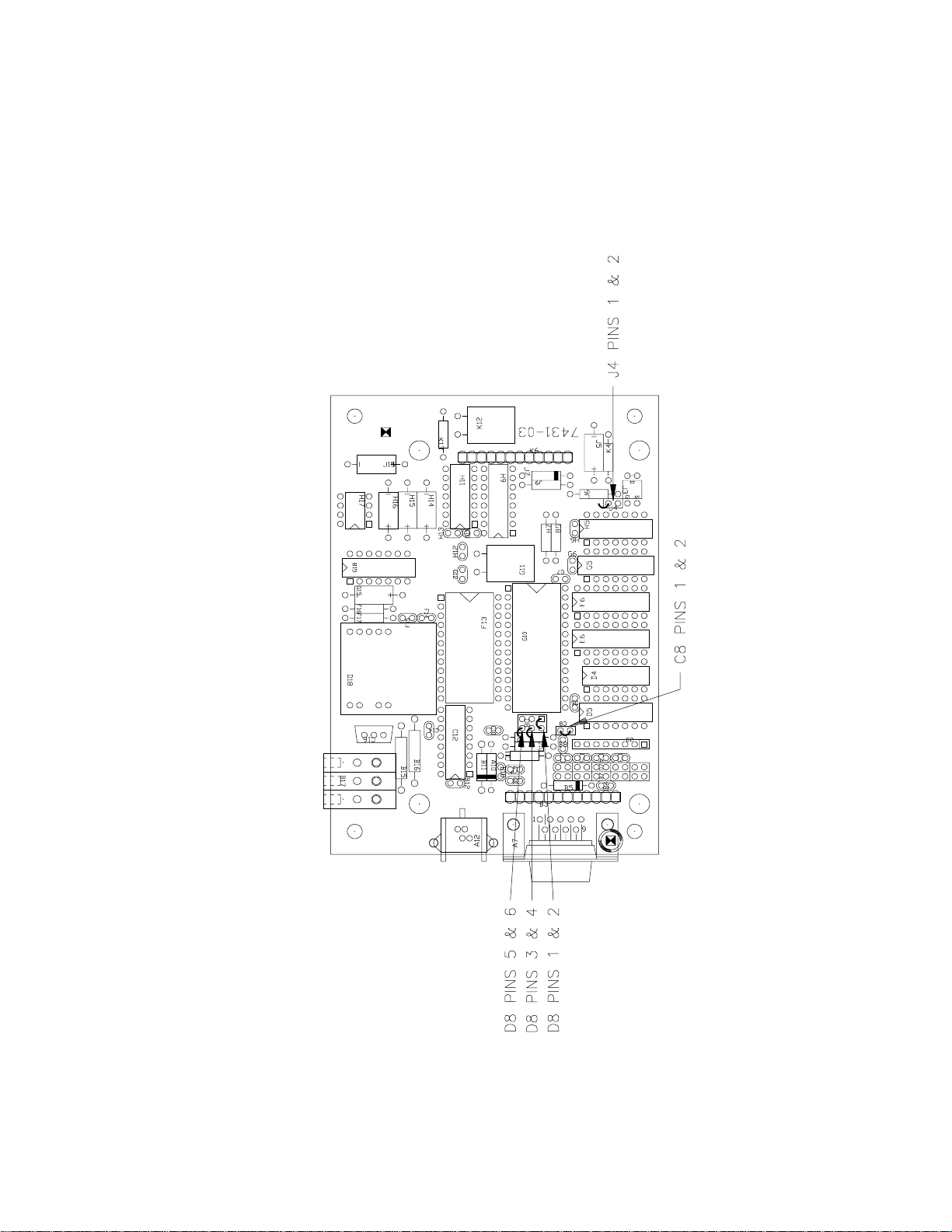
3.1. INTERNAL JUMPER SETTINGS
The VS1 Voice Synthesizer has five userchangeable jumpers. Table 3-1 lists jumper
settings and their meaning along with factory
settings. See Figure 3-1 for jumper locations.
3.2. UVEPROM INSTALLATION IN THE CR10
Your CR10 will require a special UVEPROM in
order to work properly with the VS1. If the VS1
UVEPROM was not installed at the factory,
refer to the CR10 Operator's Manual, Appendix
G or to Appendix A in this manual for installation
instructions.
3.3. SITE INSTALLATION
Your VS1 is designed to be used on standard
device telephone lines. The VS1 connects to
the telephone line by means of a USOC RJ11C
jack (standard modular telephone jack).
Connection to telephone company-provided
COIN service (Central Office ImplemeNted
systems) is prohibited. Connection to party line
service is subject to state tariffs.
TABLE 3-1. VS1 Internal Jumper Settings
JUMPER PINS MEANING FACTORY SETTING
1. D8 1 TO 2 RESULT CODES ENABLED JUMPER IN PLACE
2. D8 3 TO 4 AUTO-ANSWER DISABLED JUMPER NOT IN PLACE
3. D8 5 TO 6 ENABLE CCITT V.22 JUMPER NOT IN PLACE
4. C8 1 TO 2 ENABLE VOICE SYNTHESIZER JUMPER IN PLACE
5. J4 1 TO 2 ENABLES MODEM ENABLE JUMPER NOT IN PLACE
JUMPER 1: Result codes are sent to your terminal screen.
JUMPER 2: Auto answer is disabled by putting the jumper in place. This option is used only
when the modem is not to answer a call.
For example: The VS1 is connected to a phone line which is to be used for both
voice and modem communication. In this situation it its best to have the datalogger
call the computer.
JUMPER 3: Selects Bell 212A (U.S. and Canada) or CCITT V.22 (Foreign). This does not mean
that the VS1 is tested and approved for all foreign countries.
JUMPER 4: Selects the option to hear voice synthesis communication over the lines. Jumper 5
needs to be OFF for voice synthesis to occur.
JUMPER 5: This option is to be used when talking with dataloggers other than the CR10 or
when talking via modem only. Jumper 4 needs to be OFF when this jumper is in
place.
2
Page 5
VS1 AND VOICE SYNTHESIZER EDITOR
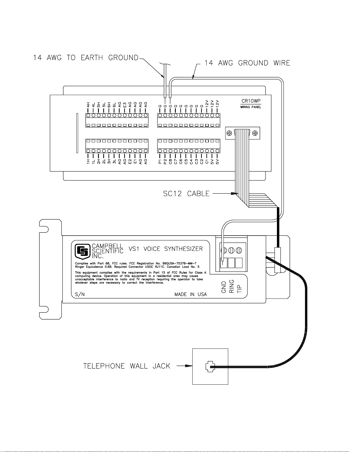
If the unit is mounted where there is a standard
modular phone plug available then connect the
phone cable provided with the VS1 from the
modular wall plug to the VS1, as shown in
Figure 3-2.
Connect the 14 AWG grounding wire (provided
with the VS1) to the grounding terminal (GND)
on the VS1. Connect the other end to the CR10
ground (G) on the wiring panel. If the enclosure
has a grounded bus bar, then connect the
ground wire to the bus bar instead of the
datalogger ground. The datalogger ground
should be tied to earth ground. See Section
14.7 in the CR10 Operator's Manual.
FIGURE 3-1. VS1 Jumper Locations
3
Page 6
VS1 AND VOICE SYNTHESIZER EDITOR
FIGURE 3-2. Standard Telephone Jack Connection
4
Page 7
VS1 AND VOICE SYNTHESIZER EDITOR
FIGURE 3-3. Remote Site Connection
5
Page 8

VS1 AND VOICE SYNTHESIZER EDITOR
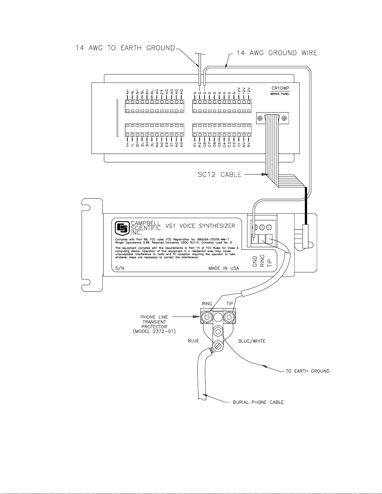
Remote datalogger installations require a
telephone transient surge protector (P/N 6362
for enclosure mount. P/N 2372-01 for direct
replacement) unless the telephone company
confirms a surge protector has already been
installed at the remote site. See Figure 3.3.
If a burial phone line and a telephone transient
surge protector are used, attach the wires to the
VS1 as shown in Figure 3-3.
NOTE: It is important that the datalogger
and VS1 are well grounded to an earth
ground to ensure proper operation.
Connect the VS1 to the CR10 via the SC12
Cable. Neither the CR10 or the VS1 use RS232
Serial I/O type pin outs or protocols to
communicate. If you would like more
information on what each pin does on the CR10
please refer to the CR10 Operator's Manual,
Section 6 on 9 PIN SERIAL INPUT/OUTPUT or
to Appendix B in this manual.
If any of your telephone equipment is not
operating properly, you should remove it
immediately from your telephone line, as it may
cause harm to the telephone network. If the
telephone company notes a problem, they may
temporarily discontinue service. When practical,
they will notify you in advance of this
disconnection. If advance notice is not feasible,
you will be notified as soon as possible. When
you are notified, you will be given the
opportunity to correct the problem and informed
of your right to file a complaint with the FCC.
give you notice in writing to allow you to make
any changes necessary to maintain
uninterrupted service.
If you have any questions about your telephone
line, such as how many pieces of equipment
you can connect to it, the telephone company
will provide this information upon request.
In certain circumstances, it may be necessary
for the telephone company to request
information from you concerning the equipment
which you have connected to your telephone
line. In this instance, provide the FCC
registration number and the Ringer Equivalence
Number (REN) of the equipment which is
connected to your line; both of these items are
listed on the equipment label and Section 2.1 of
this manual. The sum of all of the RENs on your
telephone lines should be less than five in order
to assure proper service from the telephone
company. In some cases, a sum of five may not
be usable on a given line.
For theory of operation on the modem part of
the VS1 and an "AT" command summary
please refer to Appendix E.
4. SOFTWARE INSTALLATION
The VS1 Voice Synthesizer Editor can be run
directly off the floppy disk you received with the
VS1. We recommend copying the disk to your
hard drive. It is always a good idea to make a
back up copy of your original disks and then
archive the originals. The disk is not copy
protected.
For assistance in installation or for repair, call or
write to:
Campbell Scientific, Inc.
815 West 1800 North
Logan, UT 84321-1784
(801) 753-2342.
To comply with FCC Rules and Regulations, all
repairs on the VS1 will be performed by
Campbell Scientific, Inc. or an authorized agent
of Campbell Scientific, Inc.
In order to provide you with the best service, it
may be necessary for the telephone company to
make occasional changes in their equipment,
operations, or procedures. If these changes
might affect your service or the operation of
your equipment, the telephone company will
6
Follow normal DOS COPY command
procedures to load the VS1 Voice Synthesizer
Editor onto your hard drive. The files necessary
to run the editor are: VS1.EXE and VOICE.TXT.
If there is room on the hard drive, load the
example file called EXMPL1.DLD. This file will
be used later.
5. USING THE VS1 FOR MODEM COMMUNICATIONS
In order to download files to your datalogger via
modem you will need to modify the phone
number in GRAPHTERM or TERM. Insert three
commas and "*9" at the end of the phone
number for your datalogger.
Page 9

VS1 AND VOICE SYNTHESIZER EDITOR
For example, if the number of your datalogger is
"555-4321" you would need to make the
following additions: "555-4321,,,*9".
The commas add delays so the VS1 has time to
recognize the "*9". The "*9" disables the voice
synthesizer and sets the VS1 to operate as a
standard 1200 baud modem. By inserting extra
commas into the phone number string, you can
usually correct communication problems with
the VS1. This is particularly true if the call is
long distance.
6. DOWNLOADING AND COMMUNICATING WITH THE VS1
Let's take a brief tour through the VS1. The VS1
Voice Synthesizer will allow you to monitor
preconfigured input locations in the datalogger
as well as check or manipulate flags and ports.
For this example you will need to have the
datalogger attached to the VS1 and all phone
lines connected.
Using GRAPHTERM or TERM, download
EXMPL1.DLD to the datalogger. Make sure the
datalogger is connected to the VS1. Quit
GRAPHTERM or TERM after downloading
EXMPL1.DLD.
NOTE: The datalogger does not need to be
connected to the VS1 to download a
program to it. You can download your
program via an SC32A interface, or a
storage module, to the datalogger and then
connect it up with the VS1.
6.1. INPUT LOCATIONS
Using a standard touch-tone phone, call up the
datalogger. After connecting you should hear:
Campbell Scientific datalogger program.
Datalogger internal temperature is (some value)
degrees Fahrenheit.
Press "1" for input locations.
Press "2" for ports.
Press "3" for flags.
Press "pound" to hear menu again.
Press "star" to disconnect.
The first two lines of the spoken message are
called the "Initial Message". This message is
created by the user using the VS1 Voice
Synthesizer Editor. Pressing the "#" symbol on
the telephone keypad will cause the VS1 to
repeat what is listed above. Pressing the "*"
symbol will cause the VS1 to say "goodbye" and
disconnect the phone.
For right now let's only look at the input
locations. Press "1" on your touch-tone phone.
You should hear:
You have selected to monitor input locations.
Press the pound key following your selections.
Press "1" for datalogger internal temperature.
Press "2" for datalogger battery voltage.
Press "pound" to hear menu again.
Press "star" for previous menu.
Press "1" followed by "#" on your touch-tone
phone. You should hear:
Campbell Scientific datalogger program.
Datalogger internal temperature is (some value)
degrees Fahrenheit.
Press "pound" to hear menu again.
Press "star" for previous menu.
Press "2" followed by "#" on your touch-tone
phone. You should hear:
Datalogger battery voltage is (some value)
volts.
Press "pound" to hear menu again.
Press "star" for previous menu.
Let's back completely out of the VS1 and
disconnect the phone. Press "*" followed by
another "*" on your touch-tone phone. You
should hear the VS1 say "goodbye" and then
disconnect the phone.
Pressing the "#" key by itself will cause the VS1
to repeat the menu of the input locations and
the main menu. The "#" key will not cause the
menu to be repeated in the flag or port menus.
Pressing the "*" key will always back you up to
the previous menu, unless you are in the main
menu. There, the "*" will cause the VS1 to
disconnect the phone.
You do not have to wait for the voice to finish
speaking before pressing keys. If you know the
input location you want to hear just press the
correct sequence of keys without waiting for the
voice to finish speaking.
For example, to hear the datalogger battery
voltage without waiting for the voice to finish the
initial message, call up the VS1 and press the
following sequence of keys after the line has
connected: "1", "2", "#". You should hear:
7
Page 10

VS1 AND VOICE SYNTHESIZER EDITOR
Datalogger battery voltage is (some value)
volts.
Press "pound" to hear menu again.
Press "star" for previous menu.
If you don't wish to hear the rest of the message
after hearing what the datalogger voltage level
is press "*", "*". You should hear the VS1 say
"goodbye" and disconnect the phone. The first
"*" exits you out of the input locations menu to
the main menu. The second "*" causes the VS1
to disconnect the phone.
6.2. FLAGS AND PORTS
Monitoring and changing the status of flags and
ports is almost identical. For this exercise, let's
work only with the flags.
Call up the VS1 using your phone and at the
main menu press "3" on the phone keypad to
get to the flag menu. You should hear:
You have selected the flag menu.
Press "1" through "8" to monitor status of flag.
Press "star" for previous menu.
Let's look at flag #2. Press "2" on the phone
keypad. You should hear:
Flag two is low.
To toggle flag press "pound", "pound."
Press "star" to return to previous menu.
Press "1" through "8" to monitor flag status.
Let's toggle flag #2. Press "#", "#". You should
hear:
Flag two is high.
To toggle flag press "pound", "pound."
Press "star" to return to previous menu.
Press "1" through "8" to monitor flag status."
You can skip listening to the VS1 and go directly
to the port or flag menu if you know what flag or
port you wish to monitor or toggle. You can go
through the identical steps above with the ports
menu.
WARNING: There is an inherent hazard to
being able to toggle ports and flags over the
phone. Anybody who has the phone
number to the datalogger can call up and
toggle ports and flags. You might be using
the flags to control sections of your program
in the datalogger, or you might be using the
ports to control external circuitry. The VS1
has the capability of using a security code
to lock out callers from everything but the
initial message information. See Section 8.1
in this manual on generating and using the
security code.
7. USING THE VS1 VOICE SYNTHESIZER EDITOR
7.1. GETTING STARTED
EDLOG is used to create the initial *.DLD files
and the VS1 Voice Synthesizer Editor has to
modify those files to work with the VS1. From
now on, let's refer to the VS1 Voice Synthesizer
Editor simply as the Editor.
Make sure EXMPL1.DLD is in the same
directory as the VS1.EXE file. It doesn't have to
be in the same directory, but it will make using
the Editor easier.
The Editor can be used with a mouse or with a
keyboard. Only the left mouse button is used in
VS1. Both mouse and keyboard use will be
explained. If you have a keyboard and a mouse
you can use either mouse or keyboard, or use
combinations of both.
Before disconnecting let's return flag #2 to its
original condition. Press "#", "#". You should
hear:
Flag two is low.
To toggle flag press "pound", "pound."
Press "star" to return to previous menu.
Press "1" through "8" to monitor flag status.
This is exactly what we had before. Press "*",
"*" to disconnect.
8
Instructions for mouse use will be preceded with
the symbol:
Instructions for keyboard use will be preceded
with the symbol:
The instructions for both the mouse and the
keyboard will be separated from the text by
rules.
Page 11
VS1 AND VOICE SYNTHESIZER EDITOR
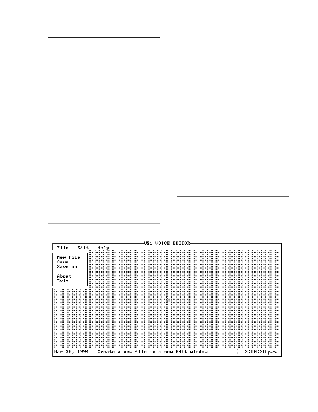
Enter the Editor by typing "VS1" <Enter>. You
should see a screen similar to Figure 7-1. Let's
describe each of the main menu options.
Through practice you should get a thorough
understanding of each option. VS1 will always
come up with the FILE main menu option
highlighted unless a particular file is specified at
the time VS1 is booted up. There are several
ways to move from option to option.
The following convention will be used
concerning keyboard keys. Special use
keys will be surrounded by <>. For
example, when you are requested to
press the "Enter" key it will look like
this: press <Enter>. Combinations of
keys, such as pressing the "Alt" key
simultaneously with the "F3" key will
look like this: press <Alt> <F3>.
Put the mouse cursor anywhere on the
main menu option you want and click
the left mouse button to select.
For keyboard use do the following:
• Use the right or left arrow keys to
highlight a different main menu option.
• Press and hold <Alt> followed by the
first letter of the main menu option.
Release both keys together.
Let's describe each individual main menu option
and suboption starting with the FILE main menu
option. Use the keyboard or the mouse to
highlight FILE.
7.2. THE FILE MAIN MENU OPTION
Don't select any of the suboptions at this time.
The various suboptions and a brief description
under the FILE option are as follows:
NEW FILE - opens a user selected *.DLD
file to be edited.
SAVE - saves the present *.DLD file that
has been loaded into VS1 for editing.
SAVE AS - allows you to save the present
file being edited under a different file name.
ABOUT - gives a brief description of the
VS1 Editor and its version number.
EXIT - leaves the VS1 editing environment
and returns you to the DOS prompt. VS1
will warn you if you try to exit without saving
a file previously selected for editing.
You can also exit VS1 from the main menu by
pressing <Esc>.
If you have a mouse, place the mouse
cursor on the suboption you want and
click the left mouse button to select
.
FIGURE 7-1. VS1 Text Editor Initial Window
9
Page 12

VS1 AND VOICE SYNTHESIZER EDITOR
Let's go through and explain each of the main
options and suboptions first. Highlight the EDIT
option.
7.3. THE EDIT MAIN MENU OPTION
Moving through and selecting the various
suboptions while in the EDIT main menu option
is the same as described in the FILE option. If
you try to select any of these options without
opening a new file you will get an
INFORMATION error message. These
functions only work when there is a *.DLD file
loaded in the editor. Let's go through and
explain each of the suboptions.
Again, don't select any of the suboptions. Now
highlight the HELP main menu option.
From the keyboard you can select a
suboption by:
• Pressing the key on the keyboard that
matches the highlighted key on each
suboption. For example, to get the
SAVE suboption you would press <S>
on the keyboard.
• Using the up or down arrow keys to
highlight different suboptions, then
press <Enter>.
EDIT LINE - edits the highlighted line in the
editor.
DELETE LINE F3 - deletes the highlighted
line in the editor. You can also delete a
highlighted line by pressing <F3>.
INSERT LINE F4 -inserts a line in the
highlighted location. You can also insert a
line by pressing <F4>. If you try to insert a
line at a location that already contains text
the new line will be inserted above the old.
See Section 7.5 for more information.
STRING MENU - creates a security code to
lock callers out from changing flags or
ports. Allows the user to change the VS1
default words used to describe the input
location menu string, port menu string, and
flag menu string. See Section 8 in this
manual for more details.
INITATE CALL - associates particular flag
settings in the CR10 with phone numbers to
call in an initiate call situation. This
command is used in conjunction with
Instruction 97 used with the CR10. See
Section 8.4 in this manual for more details.
7.4. THE HELP MAIN MENU OPTION
Notice there is only one suboption. Go ahead
and select it by using the mouse or a keyboard.
A help window will appear in the middle of your
computer screen. Help windows can be called
up from anywhere in the Editor.
7.5. EDITING EXAMPLE USING EXMPL1.DLD
Let's go through and analyze EXMPL1.DLD and
see how the initial messages were created. We
will also do some modifications.
Enter the Editor and get into the FILE main
menu option. Select NEW FILE. The CHOOSE
A FILE window should appear in the center of
your screen.
Notice the cursor is in the NAME: area. The
cursor is presently in the INSERT mode. You
can identify this by a large blinking cursor.
Press <Ins> and notice the cursor changes to a
line in size. The cursor is now in TYPEOVER
mode. Press <Ins> again to get the cursor back
in INSERT mode. The cursor is set to come up
in INSERT mode wherever you are allowed to
type in text.
Only files that end with .DLD can be edited by
the Editor. You can select files for editing a
number of different ways.
To erase the window using a mouse,
put the mouse cursor on the OK box or
on the small solid square in the upper
left corner of the help window and click
the left mouse button. This will put you
back to the FILE main menu option.
To erase the window press <Enter>,
<O>, or <Esc>.
If you have a mouse, you can select a
file in the following ways:
• If you need to change directories put
the mouse cursor either on
DIRECTORIES or somewhere in the
directories area and click the left button.
DIRECTORIES should be highlighted.
Put the mouse cursor on the correct
directory and click the left mouse button
to highlight it.
To select the directory, quickly double
click the left mouse button while the
mouse cursor is on the highlighted
10
Page 13

VS1 AND VOICE SYNTHESIZER EDITOR
directory or put the mouse cursor on
OK and click the left mouse button.
If the number of directories to choose
from exceeds 11, you will see a vertical
bar appear on the right side of the
DIRECTORIES: area. You can move
through the directories several ways. To
move quickly through the directory
selection put the mouse cursor
somewhere on the vertical bar and click
the left mouse button. You will soon
learn where you need to click on the bar
to move quickly through the directories.
To move slowly through the directories,
put the mouse cursor on the up or down
arrow located on the vertical bar. Click
and release the left mouse button to
move slowly through the listing or click
and hold the left mouse button to scroll
faster. Release the left mouse button to
stop scrolling. Use the same methods
described above to select the directory
you want.
Notice the moving rectangle in the
vertical bar as you scroll through the
directories. This rectangle indicates
your place in the directory listing.
• Select a file by putting the mouse
cursor either on FILES: or somewhere
in the files area and then clicking the
left mouse button. Selecting a file is
done the same way you select
directory, except that as soon as you
select a file you will enter the editing
environment and exit the CHOOSE A
FILE window.
From the keyboard you can do the
following:
1. While in the NAME: area type in the
name of the file you wish to edit and
press <Enter>. If the file is in a different
drive and/or directory then type in the
path and then the name of the file. You
must include the .DLD extension on the
file name. The cursor can be moved
around in the NAME: area using the
right or left arrow keys.
2. Use the <Tab> key to highlight
DIRECTORIES: If the *.DLD file is in a
different drive or directory. Use the up
or down arrow key to highlight the drive
and/or directory. To scroll quickly
through the selections press and hold
the arrow key. To stop scrolling release
the arrow key. Once the correct drive
and/or directory is highlighted press
<Enter> to select the drive and/or
directory or <Tab> over and highlight
the OK and press <Enter>.
3. After you are in the correct drive and/or
directory, use the <Tab> key or <Shft>
<Tab> to highlight the FILES: section.
Use the up or down arrow keys to move
through the files and highlight the file
you wish to edit. You can scroll with the
<PgUp> and <PgDn> keys.
At the bottom of the CHOOSE A FILE
window you will see the present
directory, file name presently
highlighted, and file creation date
information. Press <Enter> to select
the file for editing, or use <Tab> to
highlight OK and press <Enter>.
Only 11 files or drive/directories will show in the
FILES: or DIRECTORIES area at any given
time. If you would like to move through the files
or directories faster, use <PgUp> and <PgDn>.
The CANCEL option in the CHOOSE A FILE
window will cause the window to close with no
choices being made. If there are no files loaded
into the Editor you will get an INFORMATION
warning asking you if you want to quit or
continue. Selecting QUIT will exit you out of the
Editor and back into DOS. Selecting
CONTINUE will take you back to the CHOOSE
A FILE window.
If you need help while in the CHOOSE
A FILE window, place the mouse cursor
on HELP and click the left mouse
button. To exit the HELP window, either
place the cursor on OK or on the solid
square in the upper left hand corner of
the HELP window and click the left
mouse button.
For keyboards, either <Tab> over to
HELP and press <Enter>, or press
<Alt> and <H> simultaneously and
release. To exit the HELP window,
press <Enter>, <Esc>, or <O>.
11
Page 14

VS1 AND VOICE SYNTHESIZER EDITOR
Select EXMPL1.DLD from the FILES: area. The
CHOOSE A FILE window will close and you will
see a new window with the name of the
directory and file at the top of the window (See
Figure7-2). Inside the window you should see
two lines of text.
To select CANCEL using a mouse,
place the mouse cursor on CANCEL
and click the left mouse button. Placing
the mouse cursor on the solid square in
the upper left hand corner of the
CHOOSE A FILE window and then
clicking the left mouse button has the
same effect as the CANCEL option.
You can select CANCEL from the
keyboard by using <Tab> or <Shft>
<Tab> to highlight CANCEL and then
press <Enter>. Pressing <Esc> has the
same effect as the CANCEL option.
When you called the datalogger earlier, it went
through a message concerning the internal
temperature of the datalogger as soon as the
receiver was picked up. This message is called
an INITIAL MESSAGE.
Notice the first line in EXMPL1.DLD is
highlighted and has an "I" on the far left side.
This indicates this line is an initial message and
will be spoken whenever someone calls the
datalogger. You can have as many initial
messages as you like but the VS1 will only
speak them in the order they are entered in the
Editor. This order is from top to bottom as you
see them in the Editor.
In the column to the right of the "I" you should
see the name of the input memory location
used in EXMPL1.DLD. Each input location line
is associated with a specific input memory
location in the datalogger.
12
FIGURE 7-2 Edit Screen for EXMPL1.DLD
Page 15

VS1 AND VOICE SYNTHESIZER EDITOR
To select a line to edit, place the mouse
cursor on the line you wish to edit. Click
the left mouse button once to highlight
the line to select it, then quickly double
click the mouse button while the mouse
cursor is still on the highlighted line.
If the line of text you want is out of the
present window, place the mouse
cursor on the window frame on the
bottom or on the right hand side and
click the left mouse button. The
highlighted area should jump to another
line of text.
To scroll through the lines of text, place
the mouse cursor on either the arrows
on the bottom frame, or the arrows on
the right frame of the editing window.
Then click and hold the left mouse
button. Release it to stop scrolling. By
clicking the arrow icons you can single
step through text lines.
To select a line to edit using the
keyboard use the up or down arrow
keys to highlight different lines. To scroll
quickly through the selections press
and hold the up or down arrow key. To
stop scrolling release the key. If the
text line you are looking for is out of the
present window use <PgUp> and
<PgDn> to move through the text
entries faster and then use the arrow
keys to get to the exact line you want.
After you have highlighted the line you
wish to edit, press <Enter> to select it.
Notice the highlight bar can be moved
past text and into blank areas. Also
notice on the bottom and on the righthand side of the editing window the
frame has a different texture than on
the top or the left hand side. On both
frames there is a small rectangle with a
solid circular dot in the middle of the
rectangle. As you move the highlight
bar down through the text area the
rectangle on the bottom will move from
left to right and the rectangle on the
right hand side will move from top to
bottom. These rectangles identify
approximately where you are in the text
area and are used with the mouse to
move through the text area.
An editing window will appear in the middle of
the computer screen. From this window you can
do all the creation and editing of your
messages.
Next to the "Initial Message" area is "Decimal
Places: 4". The VS1 will speak from 0-5 digits
past the decimal. Sometimes you don't need all
the decimals spoken. "Decimal Places" is user
settable from zero to five digits spoken past the
decimal. The default is five.
Click on "Decimal Places" with the mouse or
<Tab> over to "Decimal Places" with a
keyboard to activate it. Type in <2>.
With the top line of EXMPL1.DLD
highlighted, place the mouse cursor on
the top line and click the left mouse
button once to highlight it and then
quickly double click the mouse button
again to select it for editing.
Use the arrow keys to move around in
the editing window to higlight the line to
be edited. Highlight the top line and
press <Enter> from the keyboard to
select the line for editing.
To use a mouse place the mouse
cursor on the option you want and click
the left mouse button once.
Use the <Tab> key from the keyboard
to move through the various fields and
<Enter> to select an option.
Notice the "Initial Message" box has an
"X" checked in it. This particular input
location has been flagged to be heard
in the initial message. Clicking on the
box with the mouse or pressing the
space bar will cause this box to be
checked or unchecked.
To exit this field with a mouse, click on
another field or click on OK.
13
Page 16

VS1 AND VOICE SYNTHESIZER EDITOR
As you scroll through the line of text you will see
"DATALOGGER INTERNAL TEMPERATURE"
in double quotes and a "$" sign followed by a
number. The words in double quotes is the input
location name and the number following the "$"
sign is an input memory location in the
datalogger. The input location name is
associated with the memory location by the
VS1. Every line must contain one input location
name associated with one memory location.
The VS1 will give a verbal list of input locations
and their names when a user calls the
datalogger and requests to monitor input
locations. Users only have access to input
locations that are associated with an input
location name.
The VS1 has a limited vocabulary of 199 words.
A list of these words can be found in Appendix
C. To enter words into the input location line you
can either type them in directly using all capital
letters and the word list, or use the option called
"List" which allows you to copy and paste words
into the input location line.
Let's modify the existing list of input locations
and add an additional line. Place the cursor on
the first letter in the word "FAHRENHEIT".
To exit using a keyboard, press <Tab>
to move to another field.
Use a mouse or the <Tab> key to
highlight the input location line. You will
see a flashing cursor at the beginning
of the input location line.
To move through the line, use the right
or left arrow keys to move letter by
letter. To move quickly through the line,
use the <Home> and <End> keys. If the
line is very long and takes up more than
one full window of characters, the
<End> key will not move the cursor to
the end of the sentence. Pressing
<End> and then the left arrow key will
take the cursor to the end of the line.
If you are using a mouse, place the
mouse cursor on the "List" option and
click the left mouse button once.
Notice the cursor has moved to the front of the
line. The cursor will automatically go to the front
of the input location line whenever you leave or
return to it. Go to the end of the line. Notice
"CELSIUS" has been inserted where the cursor
was when you moved to the word list.
Delete the word "FAHRENHEIT" using the
<Delete> key. Make sure the line terminates
with a period. Move the cursor to "$" and delete
everything up to the letter "D" in the word
"DEGREES". Leave the cursor on the "D" in the
word "DEGREES".
The DATALOGGER LABELS window will
appear in the middle of your screen. This
window contains all the input memory locations
and their labels from the EXMPL1.DLD
program. Select LOG TEMPC from the list in
the same way you selected words from the
word list. Once you are back into the input
location line, move the cursor to where you
inserted the new memory location. You will only
see the input memory location number.
For a keyboard, press <F2> to set up
the editor to import words. <F2> puts
the editor in the copy and paste mode
for the word list. You can’t transfer in a
word from the word list via keyboard
any other way.
The WORD LIST window will appear in
the center of your screen. To select a
word to copy and paste, you must first
highlight it. The highlight area can be
moved around the same as was done
earlier to select a directory and file.
Both mouse and keyboard control is the
same except the right and left arrows
can be used as well as the up and
down arrow keys. Highlight the word
"CELSIUS" and double click the left
mouse button if using a mouse or press
<Enter> from the keyboard.
To insert the memory location number
using a mouse, click on the LABELS
option.
To use a keyboard, press <F7> to get
into the LABELS option. The <F7> key
puts the Editor in copy and paste mode
for labels. The same restrictions apply
to using <F7> as to what was explained
for <F2> above.
14
Page 17

VS1 AND VOICE SYNTHESIZER EDITOR
Use the mouse or the <Tab> key to get to the
OK option. Double click the mouse or press
<Enter> to save your changes.
Notice the input memory location at the front of
the input location line has changed from LOG
TEMPF to LOG TEMPC.
Up to this point, we have altered the initial
message to give us the internal temperature of
the datalogger in degrees Celsius. Next, let's
get the datalogger to tell us it's internal
temperature in degrees Fahrenheit.
Move the highlight area in the Editor to the
second line. Get into the EDIT main option by
either placing the mouse cursor on EDIT and
clicking the left mouse button once or pressing
<Alt> <E> from the keyboard.
If you don't wish to save your changes,
put the mouse cursor on the solid
square in the upper left-hand corner
and click the left mouse button.
Using the keyboard, press <Esc> or
<F10>.
out of the Editor and download the file to your
datalogger.
Call the datalogger and notice the extra input
location and the changes you made to the file.
Let's take those changes out. Type:
vs1 exmpl1
at the cursor and press <Enter>. The Editor will
automatically call up your file and put you in the
editing mode. This is a handy shortcut if you
already know the name of the file you wish to
edit.
Move the highlighted area down to the second
line and press <F3>. The <F3> key is the
function key command to delete a line. You
could have also deleted the line by getting into
the EDIT main menu option and pressing <D>.
The second line has been removed.
CAUTION: When you delete anything using
the Editor it is gone. Be careful when you
use DELETE.
Most of the editing functions can be accessed
through function keys directly from the Editor or
by getting into the main edit menu in this
manner. Press <I> to insert a line. The next
window will ask you what kind of line you wish to
edit. Select INPUT LOCATION.
Highlight the input location window. Using LIST
and LABEL options, type in the following line:
"DATALOGGER INTERNAL TEMPERATURE
IN DEGREES FAHRENHEIT" IS $3.
After every word you import into your line press
<End> to get to the end of the line and import
the next word. The line must be terminated with
a period. After the line is completed, use OK to
save the line you created.
Notice the line is inserted ahead of the BAT
VOLT line. If you wanted to insert the line after
BAT VOLT you would have moved the
highlighted area past the BAT VOLT line and
then selected the INSERT option.
Let's run the changes. Use the mouse or press
<Alt> <F> to get into the file main menu options
and select <S>ave to save your changes. Exit
Let's leave the rest of the file as it is and save
these changes.
Download the file to the datalogger and
afterwards call it up to hear the changes. We
have gone through all the techniques necessary
to call up and listen to input locations.
7.6 USING THE "SAVE AS" SUBOPTION
On occasion you might wish to add some
changes to an existing *.DLD file that you have
created to work with VS1, but save it under a
different file name, and/or path. This can be
done with the SAVE AS suboption.
Here is an example on how to use this option:
Make sure EXMPL1.DLD is presently loaded in
the Editor. Select the SAVE AS suboption from
the FILE main menu option. A window will
appear in the middle of your screen showing the
existing file and it's path in the computer drive
directory.
Move the cursor over to EXMPL1.DLD and
delete EXMPL1. Insert the name TEST. You
should see the path followed by TEST.DLD. To
save the changes either tab over to OK or click
the mouse on OK. If you check into your
directory you will notice two new files:
TEST.DLD and TEST.VS1.
15
Page 18

VS1 AND VOICE SYNTHESIZER EDITOR
7.7 QUICK SAVE
The Editor appends special characters to the
end of the *.DLD file after it has been modified
and saved. These characters are vital for the
VS1 to operate. These special characters are
lost if you change a modified *.DLD file using
EDLOG and then save it.
If you decide to change some of the datalogger
instructions in a previously modified *.DLD file,
using EDLOG, but don't want to change any
input memory locations, there is a simple way to
modify it to work with the VS1. At the DOS
prompt, type the following:
vs1 [path][filename] /s <Enter>
The path is required if the *.DLD file is not in the
same directory as VS1.EXE. It isn't required to
put the .DLD extension at the end of your
filename. You should see the Editor briefly
appear on your screen. It will modify the file,
then save it.
8. ADDITIONAL FEATURES
8.1 SETTING THE SECURITY CODE
code you will be able to change flag and port
settings from your touch-tone phone.
The security code used with the VS1 is not the
same security code you can use with the
datalogger. See the CR10 OPERATOR'S
MANUAL for more information.
Exit the VS1 as normal.
NOTE: Remember to write this number
down. The datalogger WILL NOT let you
alter any of the ports or flags if you do not
enter this number.
8.2 RENAMING MENU STRINGS FOR INPUT LOCATION, PORTS, AND FLAGS
The Editor will allow you to rename the input
location, port, and flag strings. These strings
are what you hear when you call the datalogger.
The STRING MENU suboption in the EDIT
main menu option is used to rename these
strings. You must use words that are presently
in the vocabulary list. In order to change an
input string:
A four digit security code can be used with the
VS1 to prevent users from setting or resetting
flags or ports. To implement this into your
program do the following:
1. Load your program into the Editor.
2. Select the EDIT main menu option and the
STRING MENU suboption.
3. A window will appear in the center of your
screen with the SECURITY CODE: field
highlighted. Enter a four digit number into
this field.
4. To save your security code either <Tab> to
OK and press <Enter>, or if you have a
mouse, click on the OK.
If you do forget this number you can reenter the
Editor and go back into your file to see what
security number you originally created.
When the VS1 is called up by telephone it will
eventually ask you to enter the security code
followed by the pound button on the telephone.
Enter your specific security code followed by the
pound button. For example, if my security code
was "1234" I would enter "1234#" from my
touch-tone phone. After entering your security
1. Enter your program into the Editor.
2. Select the EDIT main menu option. Select
the STRING MENU suboption.
3. Use the <Tab> key or your mouse to
highlight the string field you wish to change.
4. Delete the present string setting using the
<Del> key.
5. Either type in a word from the word list or
import a word using the same method to
create input message strings.
6. Save your changes from the keyboard by
using <Tab> to highlight OK and press
<Enter>. If you have a mouse put the
mouse cursor on OK and click the left
mouse button.
8.3 USING THE VS1 TO HEAR OUTPUT LOCATION DATA
Output data is normally stored in the
datalogger's ring memory. This prevents VS1
from getting access to the data stored there. In
order to hear the present output data it needs to
be diverted to an input location and then use
this input location with the VS1.
16
Page 19

VS1 AND VOICE SYNTHESIZER EDITOR
Use Instruction 80 to divert output location data
to an input location. See the CR10 Operator's
Manual for information on Instruction 80. The
following is an example of a *.DLD file using
Instruction 80.
*******************************************************
*
THE NEXT SECTION DIVERTS 60 MINUTE
MAXIMUM DATA GOING INTO THE OUTPUT
SECTION TO THE INPUT DATA SECTION.
*******************************************************
*
02: P 11 Temp 107 Probe
01: 1 Rep
02: 1 IN Chan
03: 1 Excite all reps w/EXchan 1
04: 4 Loc [:AIR TEMPC]
05: 1 Mult
06: 0.0000 Offset
.
.
.
.
32: P 92 If time is
01: 0000 minutes into a
02: 60 minute interval
03: 10 Set high Flag 0 (output)
33: P80 Set Active Storage Area
01: 3 Input Storage Area
02: 5 Array ID or location
34: P73 Maximize
01: 1 Rep
02: 11 Value with Hr-Min-Sec
03: 4 Loc AIR TEMPC
Every sixty minutes the maximum air
temperature information will be diverted to input
location #5. No output data will be sent to the
datalogger ring memory.
Instruction 80 needs to follow the instruction
setting Flag 0 and preceding the output
instruction. Keep in mind that all output
processing instructions following Instruction 80
will be diverted to an input memory location until
another Instruction 80 is used to reroute data. It
is best to use Instruction 80 at the end of your
program to make sure you divert only what you
want.
8.4 USING THE VS1 TO INITIATE CALLS
The VS1 can be used to initiate calls to specific
phone numbers in voice or modem mode when
preset datalogger conditions are met. The
original *.DLD file created using EDLOG will
require specific instructions as well as using the
Editor to modify the EDLOG created *.DLD file
to initiate calls.
8.4.1 INITIATE VOICE CALLS
To initiate voice calls you will need to include
Instruction 97 in your *.DLD file. This instruction
uses a modem option code that may or may not
be on the prompt sheet or in the CR10
Operator's Manual that came with your
datalogger. The rest of the information
concerning Instruction 97 in the manual is
correct.
Modem option code 31 is used with Instruction
97 to initiate voice calls.
NOTE: Do not follow Instruction 97 with
Instruction 63. It is not needed to initiate
voice calls.
If EDLOG is being used to create the program it
will highlight modem option code 31 as an error.
Press <Enter> and it will eventually take it. In
order for Instruction 97 to initiate you will need
to decide on the condition to reset your flag and
which flags to set. See the CR10 Operator's
Manual for more information.
To initiate voice calls in your *.dld program use
the Editor to do the following:
1. Load your *.DLD file into the Editor after it
has been created in EDLOG.
2. Once in the Editor, highlight the line that will
initiate the call and pull it up for editing.
3. Highlight the "Initiate Call Flag [1..8]" field
and enter the number of the flag you are
using in your *.DLD program to initiate the
call. The "Initiate Call Flag [1..8]" field will
only appear if the correct Instruction 97 is in
the *.DLD file being edited.
4. Save your changes.
5. Either press <F6> or call up the "Initiate
call" suboption from the EDIT main menu
option. You should see a window appear in
the middle of your screen showing all the
user flags available for the CR10 and an
area to put in a phone number.
17
Page 20

VS1 AND VOICE SYNTHESIZER EDITOR
6. Enter the phone number the VS1 is to call
7. Move the cursor to the OK field to save your
Below is an example of a .DLD file that has
incorporated Instruction 97 to initiate a voice
call.
* 1Table 1 Programs
01: 60Sec. Execution Interval
02: P86Do
03: P91If Flag/Port
04: P89If X<=>F
If you have a mouse use the mouse
cursor to check the box in front of the
correct flag.
For keyboards use the <Tab> to go to
the appropriate box in front of the flag
and press the space bar to check the
box.
in the PHONE NUMBER: field. Do not use
parenthesis around the phone numbers.
The numbers can be all grouped together or
separated with a hyphen (-).
changes and exit.
01: P10Battery Voltage
01: 1Loc [:BAT VOLT ]
01: 12Set high Flag 2
01: 21Do if flag 1 is low
02: 30Then Do
01: 1X Loc BAT VOLT
02: 4 <
03: 10.5F
04: 22Set low Flag 2
If the battery voltage should fall below 10.5 VDC
the datalogger will initiate voice call. Notice how
the flags are used to control Instruction 97.
Flag 1 is used by the user to disable the
callback routine. If the datalogger detects an
alarm condition it will attempt to call the phone
number everytime the alarm condition is
met.When the VS1 initiates a voice call it does
not allow the user to listen to any of the initial
messages or get at any of the flag or port
locations. The voice call delivers the the initial
message line that has been flagged. To disable
the alarm condition the user would need to call
the datalogger back and set flag 1 high. After
the alarm condition is past, or corrected, flag 1
would need to be set back to low.
8.4.2 INITIATE MODEM CALLS
The Editor is not used to modify the *.DLD file to
initiate modem calls. To implement modem
calls in a *.DLD file you will need to use
Instruction 97 followed by Instruction 63.
Instruction 97 will require a special modem
option code.
The instruction to initiate modem calls is
Instruction 97 with modem option code 41.
If EDLOG is being used to create the program it
will highlight modem option code 41 as an error.
Press <Enter> and it will eventually take it. In
order for Instruction 97 to initiate you will need
to decide on the condition to reset your flag and
which flags to set. See the CR10 Operator's
Manual for more information.
Follow Instruction 97 with Instruction 63 to
include the phone number the datalogger is to
call.
05: P95End
06: P97Initiate Telecomm
01: 31Modem/Baud Option
02: 2Disabled when User Flag 2 is high
03: 40Seconds Call Time Limit
04: 30Seconds Before Fast Retry
05: 3Fast Retries
06: 0000Minutes Before Slow Retry
07: 3Failures Loc [:ERRORS ]
08: 100Datalogger ID
07: P End Table 1
18
An example of a .DLD file that has incorporated
Instruction 97 and 63 to initiate a modem call
follows.
* 1Table 1 Programs
01: 60Sec. Execution Interval
01: P11Temp 107 Probe
01: 1Rep
02: 1IN Chan
03: 1Excite all reps w/EXchan 1
04: 4Loc [:AIR TMP C]
05: 1Mult
06: 0Offset
Page 21

VS1 AND VOICE SYNTHESIZER EDITOR
02: P86Do
01: 11Set high Flag 1
03: P91If Flag/Port
01: 22Do if flag 2 is low
02: 30Then Do
04: P89If X<=>F
01: 4X Loc AIR TMP C
02: 3 >=
03: 40 F
04: 21Set low Flag 1
05: P95End
06: P97Initiate Telecomm
01: 41Modem/Baud Option
02: 1Disabled when User Flag 1 is high
03: 40Seconds Call Time Limit
04: 0Seconds Before Fast Retry
05: 00Fast Retries
06: 0000Minutes Before Slow Retry
07: 3Failures Loc [:ERRORS ]
08: 123Datalogger ID
07: P63Extended Parameters
01: 5 5
02: 5 5
03: 5 5
04: 4 4
05: 3 3
06: 2 2
07: 1 1
08: 13
Flags 1 and 2 are used the same way as in the
example for 8.4.1 except their roles are
reversed.
This program will initiate a modem call if the air
temperature should exceed 40°C. See your
PC208 manual for instructions on setting up
your PC to receive modem calls.
8.4.3 MIXING MODEM AND VOICE CALLS
the *.DLD file. This information can be checked
to make sure it is accurate.
A copy of the VS1 information added to the end
of EXMPL1.DLD follows. The numbers between
the "smiley faces" and the "&" symbols are the
numbers associated with the words used from
the word list. The "smiley face" is equivalent to
control code A (^A). Turn to Appendix C to see
the word list used with the VS1.
The first line is the wording used for input
locations. The second line is the wording used
for port. The third line is the wording used for
flag. The lines following are used for initial
message descriptions. Each initial message will
terminate with a period.
Line four starts with "\4". The number following
the slash indicates the number of digits
following the decimal point that the VS1 will
speak.
The numbers inside of quotation marks is the
wording for the input location.
The number(s) following the "$" symbol are the
input memory location numbers used in the
datalogger.
;|#"-56&-57&"#
#"-53&"#
#"-52&"#
>\4-88&-89&-109&-74&-71&-71&-71&"
-
109&-135&-86&"-85&$3-87&-122&.\
\4"-109&-98&-191&"-85&$1-192&.\
|
♣♣
If the datalogger has been programmed to
initiate voice calls you will see the phone
number associated with the call command at
the very end of the listing. The flag number
used to initiate the call and the phone number
will be between "at" symbols (@).
You can intermix voice and modem calls in the
same program. Make sure you are not using the
same flag for a voice and a modem call. Set up
the different types of calls as shown in the
previous two sections.
8.5 READING VS1 INFORMATION FROM A *.DLD FILE
After an editing process is completed the
information for the VS1 is added to the end of
19
Page 22

VS1 AND VOICE SYNTHESIZER EDITOR
This example initiates a voice call:
;|#"-56&-57&"#
#"-53&"#
#"-52&"#
><2\4"-98&-191&"-85&$1-192&.\
@2555-1234@
|
♣♣
Notice line four starts out as "2\4". The "2" in
front of the "4" indicates the flag number that is
used to initiate a voice call. The "2" appears
again in front of the phone number.
This last example uses the security code "1234"
to allow access. Notice the characters following
the "?" at the beginning of the character stream.
The security code will always be the very first
thing in the imbedded character portion of the
*.DLD file.
;|?1234#"-56&-57&"#
#"-53&"#
#"-52&"#
>\4-88&-89&-109&-74&-71&-71&-71&"
-
109&-135&-86&"-85&$3-122&.\
\4"-109&-98&-191&"-85&$1-192&.\
|
♣♣
20
Page 23

APPENDIX A. CHANGING RAM OR PROM CHIPS IN THE CR10
The CR10 has two sockets for Random Access
Memory (RAM) and one socket for
Programmable Read Only Memory (PROM).
The standard CR10 has 64K of RAM, (a 32K
RAM chip in each socket). Earlier CR10s had
16K of RAM (an 8K RAM chip in each socket).
A.1 DISASSEMBLING THE CR10
The sockets provided for RAM and PROM are
located on the CR10 CPU circuit card inside the
CR10 can. To expose the RAM and PROM
sockets, remove the two Phillips head screws
from the end opposite the connectors. Remove
the end cap. The ends of two circuit cards and
the RF shield will be visible (see Figure A-1).
Now lay the CR10 on a flat surface, (i.e., a
table), and push on the RF shield with your
thumbs while grasping the can with your hands.
Remove the circuit cards from the can. Orient
the cards with the connector on the left and with
the card that matches Figure A-2 up. The
Central Processing Unit (CPU) is found at
location H-9 and the three slots for RAM and
PROM will be directly beneath it.
A.2 INSTALLING NEW RAM CHIPS IN
CR10S WITH 16K RAM
The two 8K RAM chips are found at locations C11 and C-14. With a small flat screw driver
gently pry out the two 8K RAM chips at these
locations and replace them with the 32K RAM
chips provided in the memory upgrade. The
new chips should be installed so the notched
end is towards the nearest card edge. Before
pushing the chips into the socket make certain
that all the pins are correctly seated. After
installing the 32K chips check for pins that may
be bent or not firmly seated in the socket. If you
notice a bent pin, remove the chip, carefully
straighten it and repeat the installation
procedure.
A.2.1 CHANGING JUMPERS
There are six jumpers used to configure
hardware for different RAM sizes. Figure A-2
shows the jumper settings for different memory
configurations. A pin or small screw driver tip
will work best for pulling these jumpers and
relocating them as shown in Figure A-2.
A.2.2 RAM TEST
Attach the CR10KD Keyboard/Display and apply
power to the CR10. After the CR10 executes
the RAM/PROM self test, the number 96 should
be displayed in the window. The number is the
sum of Kbytes in RAM (64) plus the number of
Kbytes in ROM (32).
A.3 INSTALLING NEW PROM
The PROM chip is found at location C8 on the
CR10 CPU board, (see Figure A-2). With a
small flat screw driver, gently pry out the PROM
chip and replace it with the new one. The new
chip should be installed so that the notched end
is towards the nearest card edge. Before
pushing the chip into the socket make certain
that all the pins are seating correctly. After
installing the chip check for pins that may be
bent or not making contact. If you notice a bent
pin, remove the chip, carefully straighten it and
repeat the installation procedure.
To make certain that the new chip is installed
correctly enter the CR10 *B mode, (Section 1.6
in the CR10 Operator's Manual), and advance
to the second window. This window displays
the PROM signature. The five digit number in
the window should match the PROM signature
given with the new PROM documentation. If
the numbers are different disassemble the
CR10 and look for pins that are bent or not
firmly seated.
A-1
Page 24

APPENIDX A. CHANGING RAMOR PROM CHIPS IN THE CR10
FIGURE A-1. Disassembling CR10
A-2
FIGURE A-2. Jumper Settings for Different RAM Configurations
Page 25

APPENDIX B. 9 PIN SERIAL INPUT/OUTPUT
B.1 PIN DESCRIPTION
All external communication peripherals
connect to the CR10 through the 9-pin
subminiature D-type socket connector located
FIGURE B-1. 9 Pin Connector
TABLE B-1. Pin Description
ABR = Abbreviation for the function name.
PIN = Pin number.
O = Signal Out of the CR10 to
a peripheral.
I = Signal Into the CR10 from
a peripheral.
PIN ABR
1 5V O 5V: Sources 5V DC,
2 SG Signal Ground:
3 RING I Ring: Raised by a
4 RXD I Receive Data: Serial
5 ME O Modem Enable: Raised
I/O Description
used to power
peripherals.
Provides a power return
for pin 1 (5V), and is
used as a reference for
voltage levels.
peripheral to put the
CR10 in the
telecommunications
mode.
data transmitted by a
peripheral are received
on pin 4.
when the CR10
determines that a
modem raised the ring
line.
on the front of the Wiring Panel (Figure B-1).
Table B-1 shows the I/O pin configuration,
and gives a brief description of the function of
each pin.
PIN ABR
6 SDE O Synchronous Device
7 CLK/ I/O Clock/Handshake: Used
HS with the SDE and TXD
8 TE O Tape Enable: Powers the
9 TXD O Transmit Data: Serial
I/O Description
Enable: Used to address
Synchronous Devices
(SDs), and can be used
as an enable line for
printers.
lines to address and
transfer data to SDs.
When not used as a clock,
pin 7 can be used as a
handshake line (during
printer output, high
enables, low disables).
cassette recorder during
tape transfer.
data are transmitted from
the CR10 to peripherals
on pin 9; logic low marking
(0V) logic high spacing
(5V) standard
asynchronous ASCII, 8
data bits, no parity, 1 start
bit, 1 stop bit, 300, 1200,
9600, 76,800 baud (user
selectable).
B-1
Page 26

APPENDIX C - VS1 WORD LIST
STANDARD VS1 WORD LIST IN NUMERICAL ORDER
0. ZERO
1. ONE
2. TWO
3. THREE
4. FOUR
5. FIVE
6. SIX
7. SEVEN
8. EIGHT
9. NINE
10. TEN
11. ELEVEN
12. TWELVE
26. EIGHTY
27. NINETY
28. HUNDRED
29. THOUSAND
30. MILLION
31. PRESS
32. POUND
33. DEW
34. HEAR
35. MENU
36. AGAIN
37. STAR
38. DISCONNECT
52. FLAGS
53. PORTS
54. THRU
55. PORT
56. INPUT
57. LOCATIONS
58. FLAG
59. AND
60. OF
61. SECURITY
62. CODE
63. YOUR
64. POINT
13. THIRTEEN
14. FOURTEEN
15. FIFTEEN
16. SIXTEEN
17. SEVENTEEN
18. EIGHTEEN
19. NINETEEN
20. TWENTY
21. THIRTY
22. FORTY
23. FIFTY
24. SIXTY
25. SEVENTY
39. YOU
40. THE
41. HAVE
42. SELECTED
43. MONITOR
44. KEY
45. FOLLOWING
46. RETURN
47. PREVIOUS
48. STATUS
49. HIGH
50. LOW
51. TOGGLE
65. PLEASE
66. BY
67. MINUS
68. ENTER
69. SELECTION
70. GOODBYE
71. PAUSE(50MS)
72. MESSAGE
73. CALLBACK
74. PROGRAM
75. SIGNATURE
76. EPROM
77. KILOBYTES
C--1
Page 27

APPENDIX C. VS1 WORD LIST
78. MEMORY
79. NUMBER
80. E08'S
81. TABLE
82. OVERRUNS
83. VERSION
84. REVISION
85. IS
86. TEMPERATURE
87. DEGREES
88. CAMPBELL
89. SCIENTIFIC
90. ACRE
106. CURRENT
107. DAM
108. DATA
109. DATALOGGER
110. DAY
111. DEPTH
112. DEVIATION
113. DIRECTION
114. D-O
115. DOWN
116. DRAW
117. EQUAL
118. ET
134. INCHES
135. INTERNAL
136. KILO
137. LAST
138. LEVEL
139. LITER
140. RESET
141. MAXIMUM
142. MERCURY
143. METER
144. METERS
145. MICRO
146. MILES
91. AIR
92. ALARM
93. ARE
94. AT
95. AVERAGE
96. BAROMETRIC
97. BARS
98. BATTERY
99. CALIBRATE
100. CELSIUS
101. CENTI
102. CHILL
103. CLOSED
119. EVENT
120. EXTERNAL
121. EXCEEDS
122. FAHRENHEIT
123. FALL
124. FEET
125. FLOW
126. FROM
127. GALLONS
128. GRAM
129. HELLO
130. SET
131. HOUR
147. MILLI
148. MINIMUM
149. MINUTE
150. MOISTURE
151. MONTH
152. MULTIPLIER
153. NEW
154. N-T-U
155. OFF
156. OFFSET
157. ON
158. OPEN
159. OVERFLOW
104. CONDUCTIVITY
105. CUBIC
C-2
132. HUMIDITY
133. IN
160. PARTS
161. PER
Page 28

APPENDIX C. VS1 WORD LIST
162. PERCENT
163. P-H
164. PRECIPITATION
165. PRESSURE
166. PROGRESS
167. P-S-I
168. RADIATION
169. RAIN
170. RATE
171. REFERENCE
172. RELATIVE
173. R-P-M
174. SAMPLE
175. SECOND
176. SECONDS
177. SIEMENS
178. SITE
179. SNOW
180. SOIL
181. SOLAR
182. SPEED
183. SQUARED
184. STAGE
185. STANDARD
186. STATION
187. STORM
188. TIME
189. TURBIDITY
190. VELOCITY
191. VOLTAGE
192. VOLTS
193. WARNING
194. WATER
195. WATTS
196. WEATHER
197. WELL
198. WIND
STANDARD VS1 WORD LIST IN ALPHABETICAL ORDER
90. ACRE
36. AGAIN
91. AIR
92. ALARM
59. AND
93. ARE
94. AT
95. AVERAGE
96. BAROMETRIC
97. BARS
98. BATTERY
73. CALLBACK
88. CAMPBELL
100. CELSIUS
101. CENTI
102. CHILL
103. CLOSED
62. CODE
104. CONDUCTIVITY
105. CUBIC
106. CURRENT
114. D-O
109. DATALOGGER
110. DAY
87. DEGREES
111. DEPTH
112. DEVIATION
33. DEW
113. DIRECTION
38. DISCONNECT
115. DOWN
116. DRAW
80. E08'S
66. BY
99. CALIBRATE
107. DAM
108. DATA
8. EIGHT
18. EIGHTEEN
C-3
Page 29

APPENDIX C. VS1 WORD LIST
26. EIGHTY
11. ELEVEN
68. ENTER
76. EPROM
117. EQUAL
118. ET
119. EVENT
121. EXCEEDS
120. EXTERNAL
122. FAHRENHEIT
123. FALL
124. FEET
15. FIFTEEN
129. HELLO
49. HIGH
131. HOUR
132. HUMIDITY
28. HUNDRED
133. IN
134. INCHES
56. INPUT
135. INTERNAL
85. IS
44. KEY
136. KILO
77. KILOBYTES
30. MILLION
148. MINIMUM
67. MINUS
149. MINUTE
150. MOISTURE
43. MONITOR
151. MONTH
152. MULTIPLIER
154. N-T-U
153. NEW
9. NINE
19. NINETEEN
27. NINETY
23. FIFTY
5. FIVE
58. FLAG
52. FLAGS
125. FLOW
45. FOLLOWING
22. FORTY
4. FOUR
14. FOURTEEN
126. FROM
127. GALLONS
70. GOODBYE
128. GRAM
137. LAST
138. LEVEL
139. LITER
57. LOCATIONS
50. LOW
141. MAXIMUM
78. MEMORY
35. MENU
142. MERCURY
72. MESSAGE
143. METER
144. METERS
145. MICRO
79. NUMBER
60. OF
155. OFF
156. OFFSET
157. ON
1. ONE
158. OPEN
159. OVERFLOW
82. OVERRUNS
163. P-H
167. P-S-I
160. PARTS
71. PAUSE(50MS)
41. HAVE
34. HEAR
C-4
146. MILES
147. MILLI
161. PER
162. PERCENT
Page 30

APPENDIX C. VS1 WORD LIST
65. PLEASE
64. POINT
55. PORT
53. PORTS
32. POUND
164. PRECIPITATION
31. PRESS
165. PRESSURE
47. PREVIOUS
74. PROGRAM
166. PROGRESS
173. R-P-M
168. RADIATION
7. SEVEN
17. SEVENTEEN
25. SEVENTY
177. SIEMENS
75. SIGNATURE
178. SITE
6. SIX
16. SIXTEEN
24. SIXTY
179. SNOW
180. SOIL
181. SOLAR
182. SPEED
54. THRU
188. TIME
51. TOGGLE
189. TURBIDITY
12. TWELVE
20. TWENTY
2. TWO
190. VELOCITY
83. VERSION
191. VOLTAGE
192. VOLTS
193. WARNING
194. WATER
169. RAIN
170. RATE
171. REFERENCE
172. RELATIVE
140. RESET
46. RETURN
84. REVISION
174. SAMPLE
89. SCIENTIFIC
175. SECOND
176. SECONDS
61. SECURITY
42. SELECTED
183. SQUARED
184. STAGE
185. STANDARD
37. STAR
186. STATION
48. STATUS
187. STORM
81. TABLE
86. TEMPERATURE
10. TEN
40. THE
13. THIRTEEN
21. THIRTY
195. WATTS
196. WEATHER
197. WELL
198. WIND
39. YOU
63. YOUR
0. ZERO
69. SELECTION
130. SET
29. THOUSAND
3. THREE
C-5
Page 31

APPENDIX D. EXMPL1.DLD PROGRAM
};CR10
;EXMPL1.DLD
;$
;:BAT VOLT :LOG TEMPC:LOG TEMPF
;$
MODE 1
SCAN RATE 1
1:P10
1:1
2:P17
1:2
3:P37
1:2
2:1.8
3:3
4:P34
1:3
2:32
3:3
MODE 2
SCAN RATE 0.0000
MODE 3
MODE 10
1:28
2:64
3:0.0000
MODE 12
1:0
2:0
3:0000
;|#"-56&-57&"#
#"-53&"#
#"-52&"#
>\4-88&-89&-109&-74&-71&-71&-71&"-109&-135&-86&"-85&$3-87&-122&.\
\4"-109&-98&-191&"-85&$1-192&.\
|
♣♣
D-1
Page 32

APPENDIX E. THEORY OF OPERATION
The VS1 Voice Synthesizer is used to transmit
data over bandwidth-limited channels such as
telephone lines by modulating audio tones,
using Frequency Shift Keying (FSK) at 300
baud, or Phase Shift Keying (PSK) at 1200
baud.
The telephone company gives a 40 to 150
VRMS, 20 Hz signal on the phone lines to
signify a ring, which is typically on for 2 seconds
and off for 4 seconds. The ring detection
circuitry is continuously powered but draws less
than 2 µA. The ring signal is passed on to the
datalogger through an opto-coupler. The
datalogger responds by raising the Modem
Enable line which enables the 5VDC power to
the modem. The modem then answers and
remains off-hook until it loses the carrier or the
datalogger lowers the Modem Enable line. The
datalogger lowers the Modem Enable line by
remote command or after 40 seconds in the
absence of a command. When the Modem
Enable line goes low, the 5 VDC power is
removed from the modem circuitry, dropping
power to the off-hook relay and thus placing the
phone line on-hook.
To reject noise common to both phone lines
and to satisfy registration requirements, the
modem circuitry is electrically isolated from the
phone lines by using an opto-isolator and
coupling transformer.
This manual does not attempt to be a primer on
the "AT" command set. The commands are
therefore only summarized below. For most
applications, the modem commands are issued
automatically by the PC208 software. The
commands apply only when the modem is used
as an originate modem, which is not the primary
use of this modem. Except as noted, all
commands begin with "AT" and end with
carriage return. As an example, the command
ATDT5551212 followed by carriage return will
tone dial the number that follows the ATDT,
then go on-line and wait up to 30 seconds for
the remote modem carrier. If the carrier is
detected, the result code 1 will be returned,
otherwise the result code 3 will be returned, and
the modem will return to the command mode.
COMMANDS:
AT Prefix to all commands (except /A)
A/ Repeat last command (not followed by
carriage return)
D Dial
P Pulse
T Tone
0..9 Telephone number digits
W Wait for another dial tone
; Return to command state after dialing
, Pause
Z Reset to default settings
A Answer without ring
H Hang up
O Go to on-line state
COMMANDS TO CHANGE DEFAULT MODES:
R Call an originate modem
B CCITT mode
B1 BELL 212A mode
C Carrier off
C1 Carrier on
E Commands not echoed
E1 Commands echoed
F Half duplex
F1 Full duplex
Q Return result codes
Q1 Disable result codes
Sr? What is the value in register r
Sr=n Set register r to value n
V Digit result codes
V1 Word result codes
RESULT CODES:
0OK
1 Connect
2 Ring
3 No Carrier
4 Error
REGISTERS:
S0 Rings before auto-answer (0..255)
S6 Wait for dial tone (2..255 seconds)
S7 Wait for remote carrier (1..255 seconds)
S8 Comma pause time (0..255 seconds)
S10 Delay time between loss of carrier and
hang up (1..255 in 10th of seconds)
E-1
Page 33

APPENDIX F. FCC WARNING TO USERS OF
CLASS A COMPUTING DEVICES
WARNING: This equipment generates, uses, and can radiate radio frequency energy, and if
not installed and used in accordance with the instruction manual, may cause interference to
radio communications. It has been tested and found to comply with the limits for a Class A
computing device pursuant to Subpart J of Part 15 of FCC Rules, which are designed to
provide reasonable protection against such interference when operated in a COMMERCIAL
ENVIRONMENT. Operation of this equipment in a residential area may cause interference to
radio and television reception. The operator must take whatever measures are necessary to
correct the interference.
F-1
Page 34

APPENDIX G. HELP, INFORMATION, AND ERROR MESSAGES
HELP MESSAGES
HELP 0001:
A *.DLD file has not been opened at this time.
Please open a file using the NEW FILE
command in the FILE menu.
HELP 0002:
This screen is a listing of all the strings for input
locations, ports, and flags, that are in the *.DLD
file.
If the voice strings have not been created this
screen will be blank. Some keys have special
uses in this screen. They are as follows:
Enter: Invokes the editing window for the line
highlighted.
F1: Invokes Help screens.
F3: Deletes the highlighted line.
F4: Inserts a line before the highlighted line.
F5: Enlarges the editing screen to full size.
F6: Invokes the Initiate Call Flag window.
The user can then specify the flag and
telephone number for call.
HELP 0005:
Enter in the string to specify the reset state of
the 'labell'. If the 'labell' is reset this string will
be spoken. The format of the string will be
required to end in a period. No input location
will be allowed in the string.
HELP 0006:
The initial message will be spoken when the
user calls the VS1. To include this message in
the initial messages, press the space bar. An X
in the box signifies that this string will be spoken
as an initial message.
HELP 0007:
Enter in the flag number or numbers of flags to
initiate call. Initiate Call occurs when the flag
specified in Instruction 97 is toggled. This string
will be included in the Initiate Call message
delivered to the user.
HELP 0008:
Enter in the input location string to specify the
string to be spoken. The string must be entered
in the following format: The string must have a
key word or phrase (for example: "temp") and
an input memory location $n, where n is an
input memory location from the CR10.
NOTE: Initiate Call will only work if
Instruction 97 is used in the *.DLD file. The
screen will refresh itself and update any
changes made to the strings.
HELP 0003:
Enter in the number to specify the 'labell'.
HELP 0004:
Enter in the string to specify the set state of the
'labell'. If the 'labell' is set, this string will be
spoken. The format of the string will be required
to end in a period. No input location will be
allowed in the string.
Example: THE "TEMPERATURE" IS $3
DEGREES CELSIUS.
In the example, "TEMPERATURE" is the key
word and $3 is the input memory location.
HELP 0009:
The help button invokes HELP screens for each
of the fields in the window.
HELP 0010:
The VS1 has a pre-determined list of valid
words that can be used to create the voice
strings. To invoke this list press <F2>, or click
on the "List" bar with the mouse. The user can
insert a word at the cursor position from the
word list window by using a mouse or <TAB> to
G-1
Page 35

APPENDIX G. HELP, INFORMATION AND ERROR MESSAGES
highlight a word then entering the word into the
voice string by double clicking the mouse or by
pressing <Enter>.
HELP 0011:
Press the space bar to tag (X) the flag used in
Instruction 97 in the *.DLD file. If the flag is
tagged, then the phone number will be dialed
when the associated flag is reset.
HELP 0012:
Enter in the phone number to be called.
HELP 0013:
Enter in the security code to lock out everything
but the initial messages to the user. Default is
no security code.
HELP 0014:
Enter in the string to specify the input location
name for the user to access information to input
locations of the datalogger. Default is "INPUT
LOCATIONS".
HELP 0015:
Enter in the string to specify the port name for
the user to access information to ports on the
datalogger. Default is "PORTS".
HELP 0016:
Enter in the string to specify the flag name for
the user to access information to ports on the
datalogger. Default is "FLAGS".
HELP 0017:
The help button invokes HELP screens for each
of the fields in the window.
HELP 0019:
Enter a filename (or file mask) in the Name box,
or <TAB> to the file list and select a file from the
list by pressing <Enter> or double clicking the
left button on the mouse.
To change directories, <TAB> to the Directories
list and select one.
HELP 0020:
Enter in the new name you want to save the file
under, include the path and the extension.
HELP 0021:
The VS1 has the capability to limit the number
of digits spoken to the user. By placing 0, 1, 2,
3, 4, or 5 in this field, the corresponding input
location will be limited. By default, 5 decimal
places will be spoken.
INFORMATION MESSAGES
INFORMATION 0001:
A *.DLD file has not been opened at this time.
Please open a file using the NEW FILE
command in the FILE menu.
INFORMATION 0002:
Would you like to quit or continue?
INFORMATION 0003:
'name' has been modified. Save?
INFORMATION 0004:
Is this string for 'inp', 'prt' or 'flg'?
ERROR MESSAGES
HELP 0018:
The VS1 has a pre-determined list of valid
words that can be used to create the voice
strings. To invoke this list, press <F2>, or click
on the LIST bar with the mouse. The user can
insert a word at the cursor position from the
word list window by using a mouse or <TAB> to
highlight a word then entering the word into the
voice string by double clicking the mouse or by
pressing <Enter>.
G-2
ERROR 0001:
Please use a *.DLD file.
ERROR 0002:
'name' input file not found
ERROR 0003:
voice.txt input file not found.
Page 36

APPENDIX G. HELP, INFORMATION AND ERROR MESSAGES
This file contains the word list and must be
located in the path. The program will now exit.
ERROR 0004:
There must only be one input location per line.
Please re-enter the input string.
Example: THE "TEMPERATURE" IS $4.
ERROR 0005:
'no_word' are not in the word list. Please check
the word list for valid words.
ERROR 0006:
'no_word' is not in the word list. Please check
the word list for valid words.
ERROR 0007:
Please specify the 'labell' number.
ERROR 0008:
Please end the Set string with a period.
ERROR 0009:
Please end the Reset string with a period.
ERROR 0010:
Enter in the input location string to specify the
string to be spoken. The string must be entered
in the following format: The string must have a
key word or phrase (for example "temp") and an
input memory location $n, where n is an input
location from the CR10.
ERROR 0012:
Initiate Call is not set by Instruction 97 in the
*.DLD file.
ERROR 0013:
File 'name' already exists. Overwrite?
ERROR 0014:
Extension longer than three characters.
ERROR 0015:
Illegal drive specifier.
ERROR 0016:
Illegal characters in path.
ERROR 0017:
Invalid path.
ERROR 0018:
No file specified.
ERROR 0019:
Illegal characters in name.
ERROR 0020:
Name longer than eight characters.
NOTE: Words that are inside ' ' are code
variables.
Example: THE "TEMPERATURE" IS $3
DEGREES CELSIUS.
In the example, "TEMPERATURE" is the key
word and $3 is the input memory location.
ERROR 0011:
A voice file (.vs1) does not exist for file 'name'
Would you like to create a voice file with the file
'name' ?
Example: 'labell', labell specifies either a
PORT or a FLAG.
G-3
 Loading...