

Campbell Scientific TX326 User Manual

Revision: 03/2021
Copyright © 2020 – 2021
Campbell Scientific
CSL I.D - 1346

Guarantee
This equipment is guaranteed against defects in materials and workmanship.
We will repair or replace products which prove to be defective during the
guarantee period as detailed on your invoice, provided they are returned to us
prepaid. The guarantee will not apply to:
Equipment which has been modified or altered in any way without the
written permission of Campbell Scientific
Batteries
Any product which has been subjected to misuse, neglect, acts of God or
damage in transit.
Campbell Scientific will return guaranteed equipment by surface carrier
prepaid. Campbell Scientific will not reimburse the claimant for costs incurred
in removing and/or reinstalling equipment. This guarantee and the Company’s
obligation thereunder is in lieu of all other guarantees, expressed or implied,
including those of suitability and fitness for a particular purpose. Campbell
Scientific is not liable for consequential damage.
Please inform us before returning equipment and obtain a Repair Reference
Number whether the repair is under guarantee or not. Please state the faults as
clearly as possible, and if the product is out of the guarantee period it should
be accompanied by a purchase order. Quotations for repairs can be given on
request. It is the policy of Campbell Scientific to protect the health of its
employees and provide a safe working environment, in support of this policy a
“Declaration of Hazardous Material and Decontamination” form will be
issued for completion.
When returning equipment, the Repair Reference Number must be clearly
marked on the outside of the package. Complete the “Declaration of
Hazardous Material and Decontamination” form and ensure a completed copy
is returned with your goods. Please note your Repair may not be processed if
you do not include a copy of this form and Campbell Scientific Ltd reserves
the right to return goods at the customers’ expense.
Note that goods sent air freight are subject to Customs clearance fees which
Campbell Scientific will charge to customers. In many cases, these charges are
greater than the cost of the repair.
Campbell Scientific Ltd,
80 Hathern Road,
Shepshed, Loughborough, LE12 9GX, UK
Tel: +44 (0) 1509 601141
Fax: +44 (0) 1509 270924
Email: support@campbellsci.co.uk
www.campbellsci.co.uk
About this manual
Please note that this manual was originally produced by Campbell Scientific Inc. primarily for the North
American market. Some spellings, weights and measures may reflect this origin.
Some useful conversion factors:
Area: 1 in2 (square inch) = 645 mm2
Length: 1 in. (inch) = 25.4 mm
1 ft (foot) = 304.8 mm
1 yard = 0.914 m
1 mile = 1.609 km
In addition, while most of the information in the manual is correct for all countries, certain information
is specific to the North American market and so may not be applicable to European users.
Differences include the U.S standard external power supply details where some information (for
example the AC transformer input voltage) will not be applicable for British/European use. Please note,
however, that when a power supply adapter is ordered it will be suitable for use in your country.
Reference to some radio transmitters, digital cell phones and aerials may also not be applicable
according to your locality.
Some brackets, shields and enclosure options, including wiring, are not sold as standard items in the
European market; in some cases alternatives are offered. Details of the alternatives will be covered in
separate manuals.
Part numbers prefixed with a “#” symbol are special order parts for use with non-EU variants or for
special installations. Please quote the full part number with the # when ordering.
Mass: 1 oz. (ounce) = 28.35 g
1 lb (pound weight) = 0.454 kg
Pressure: 1 psi (lb/in2) = 68.95 mb
Volume: 1 UK pint = 568.3 ml
1 UK gallon = 4.546 litres
1 US gallon = 3.785 litres
Recycling information
At the end of this product’s life it should not be put in commercial or domestic refuse but
sent for recycling. Any batteries contained within the product or used during the
products life should be removed from the product and also be sent to an appropriate
recycling facility.
Campbell Scientific Ltd can advise on the recycling of the equipment and in some cases
arrange collection and the correct disposal of it, although charges may apply for some
items or territories.
For further advice or support, please contact Campbell Scientific Ltd, or your local agent.
Campbell Scientific Ltd, 80 Hathern Road, Shepshed, Loughborough, LE12 9GX,
UK Tel: +44 (0) 1509 601141 Fax: +44 (0) 1509 270924
Email: support@campbellsci.co.uk
www.campbellsci.co.uk

Safety
DANGER — MANY HAZARD S ARE ASSOCIATED WITH INSTALLING, USING, M AINTAINING, AND WORKING ON
OR AROUND TRIPODS, TOWERS, AND ANY ATTACHMENTS TO TRIPODS AND TOWERS SUCH AS SENSORS,
CROSSARMS, ENCLOSURES, ANTENNAS, ETC. FAILURE TO PROPERLY AND COM P LE TE LY ASS E M BLE ,
INSTALL, OPERATE, USE, AND MAINTAIN TRIPODS, TOWERS, AND ATTACHMENTS, AND FAILURE TO HEED
WARNINGS, INCREASES THE RISK OF DEATH, ACCIDENT, SERIOUS INJURY, PROPERTY DAMAGE, AND
PRODUCT FAILURE. TAKE ALL REASONABLE PRECAUTIONS TO AVOID THESE HAZARDS. CHECK WITH YOUR
ORGANIZATION'S SAFETY COORDINATOR (OR POLICY) FOR PROCEDURES AND REQUIRED PROTECTIVE
EQUIPMENT PRIOR TO PERFORMING ANY WORK.
Use tripods, towers, and attachments to tripods and towers only for purposes for which they are designed. Do not
exceed design limits. Be familiar and comply with all instructions provided in product manuals. Manuals are
available at www.campbellsci.eu or by telephoning +44(0) 1509 828 888 (UK). You are responsible for conformance
with governing codes and regulati ons, including safety regulati ons, and the integrity and locati on of structures or land
to which towers, tripods, and any attachments are attached. Installation sites should be evaluated and approved by a
qualified engineer. If questions or co ncerns arise regarding installation, use, or maintenance of tripods, towers,
attachments, or electrical connections, consult with a licensed and qualified engineer or electrician.
General
• Prior to performing site or installation work, obtain required approvals and permits. Comply with all
governing structure-height regulations, such as those of the FAA in the USA.
• Use only qualified personnel for installation, use, and maintenance of tripods and towers, and any
attachments to tripods and towers. The use of licensed and qualified contractors is highly recommended.
• Read all applicable instructions carefully and understand procedures thoroughly before beginning work.
• Wear a hardhat and eye protection, and take other appropriate safety precautions while working on or
around tripods and towers.
• Do not climb tripods or towers at any time, and prohibit climbing by other persons. Take reasonable
precautions to secure tripod and tower sites from trespassers.
• Use only manufacturer recommended parts, materials, and tools.
Utility and Electrical
• You can be killed or sustain serious bodily injury if the tripod, tower, or attachments you are installing,
constructing, using, or maintaining, or a tool, stake, or anchor, come in contact with overhead o
nderground utility lines.
u
• Maintain a distance of at least one-and-one-half times structure height, or 20 feet, or the distance
r
equired by applicable law, whichever is greater, between overhead utility lines and the structure (tripod,
tower, attachments, or tools).
• Prior to performing site or installation work, inform all utility companies and have all underground utilities
marked.
• Comply with all electrical codes. Electrical equipment and related grounding devices should be installed
by a licensed and qualified electrician.
r
Elevated Work and Weather
• Exercise extreme caution when performing elevated work.
• Use appropriate equipment and safety practices.
• During installation and maintenance, keep tower and tripod sites clear of un-trained or non-essential
personnel. Take precautions to prevent elevated tools and objects from dropping.
• Do not perform any work in inclement weather, including wind, rain, snow, lightning, etc.
Maintenance
• Periodically (at least yearly) check for wear and damage, including corrosion, stress cracks, frayed cables,
loose cable clamps, cable tightness, etc. and take necessary corrective actions.
• Periodically (at least yearly) check electrical ground connections.
WHILE EVERY ATTEMPT IS MADE TO EMBODY THE HIGHEST DEGREE OF SAFETY IN ALL CAMPBELL
SCIENTIFIC PRODUCTS, THE CUSTOMER ASSUMES ALL RISK FROM ANY INJURY RESULTING FROM IMPROPER
INSTALLATION, USE, OR MAINTENANCE OF TRIPODS, TOWERS, OR ATTACHMENTS TO TRIPODS AND TOWERS
SUCH AS SENSORS, CROSSARMS, ENCLOSURES, ANTENNAS, ETC.

Table of contents
1. Introduction 1
2. Precautions 1
3. Initial inspection 1
4. QuickStart 2
4.1 Data collection platform (DCP) installation 4
5. Overview 7
5.1 Meteosat/EuroSat system 8
6. Specifications 9
7. Installation 11
7.1 Field site requirements 11
7.2 LED function 11
7.3 Ports and connectors 12
7.4 Transmission antenna 13
7.5 GPS antenna 14
7.6 Data logger programming 14
7.6.1 Read-only settings 15
7.6.2 Read and write settings 18
8. Troubleshooting 19
Appendix A. Data formats and transmission durations 21
A.1 ASCII data format 21
A.1.1 7-byte floating-point ASCII (GOESTable() format option 1) 21
A.1.2 ASCII table space (GOESTable() format option 2) 23
A.1.3 ASCII table space, comma separated (GOESTable() format option 3) 26
A.1.4 Line SHEF (Standard Hydrological Exchange Format) (GOESTable() format
option 6) 28
A.2 Pseudobinary data formats 29
A.2.1 Campbell Scientific FP2 data 30
A.2.2 Pseudobinary 35
A.2.3 Additional pseudobinary representations 35
Table of Contents - i

1. Introduction
The TX326 is a satellite transmitter that uses the Meteosat/EuroSat satellite system to provide
one-way communications from a data collection platform (DCP) to a receiving station.
Meteosat/EuroSat is a system of geostationary meteorological satellites operated by EUMETSAT
(European Organisation for the Exploitation of Meteorological Satellites). Geostationary satellites
have orbits that coincide with the Earth's rotation, allowing each satellite to remain above a
specific region. EUMETSAT is an intergovernmental organization created through an
international convention of European countries.
2. Precautions
l READ AND UNDERSTAND the Safety section at the front of this manual.
l Although the TX326 is rugged, it should be handled as a precision scientific instrument.
l A proper antenna connection is required before transmission occurs. Failure to use a
properly matched antenna cable and antenna may cause permanent damage to the radio
frequency (RF) amplifiers.
l The TX326 requires an active GPS antenna with a maximum gain of 25 dB. The TX326 will
supply 3.3 V to the active GPS antenna.
3. Initial inspection
l Upon receipt of the TX326, inspect the packaging and contents for damage. File damage
claims with the shipping company.
l Check the ships with list to ensure all components are received.
TX326 Satellite Transmitter for METEOSAT 1

4. QuickStart
Use our Device Configuration Utility to enter the required European Organization for the
Exploitation of Meteorological Satellites (EUMETSAT) information that is unique to each data
collection platform (DCP). This QuickStart is for the CR6 (≥OS 10), CR300-series (≥OS 10),
CR1000X (≥OS 4), and GRANITE-series (≥OS1) data loggers.
1. Connect the data logger RS-232 to the TX326 RS-232 connector and connect the data
logger to a power supply. Also ensure the TX326 has power.
2. Connect to the data logger using Device Configuration Utility.
a. Do the following to directly connect your data logger to the Device Configuration
Utility:
i. Use the USB cable to connect the data logger to the computer.
ii. Click your data logger model for the Device Type in the Device Configuration
Utility.
iii. Click Direct for the Connection Type.
iv. Select the COM port on the computer to which the data logger is connected.
v. Click Connect.
b. For data loggers on an IP connection, do the following to remotely connect with the
Device Configuration Utility:
i. Click your data logger model for the Device Type in the Device Configuration
Utility.
ii. Click IP for the Connection Type.
iii. Type the Server Address.
iv. Type the PakBus/TCP Password.
v. Click Connect.
3. Click the Settings Editor tab.
TX326 Satellite Transmitter for METEOSAT 2
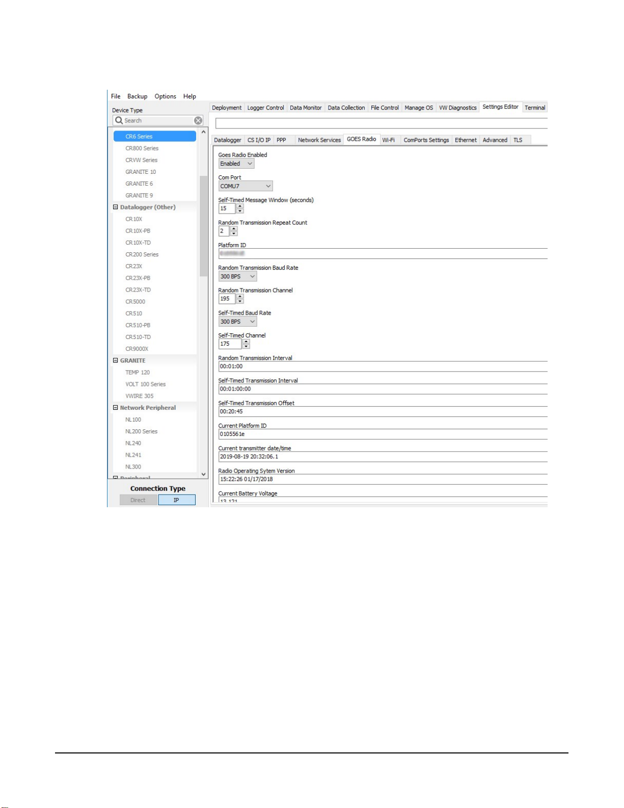
4. Click the GOES Radio sub tab (FIGURE 4-1 (p. 3)).
FIGURE 4-1. Device Configuration Utility GOES Radio screen
5. Select Enabled from the Goes Radio Enabled field.
6. Select the Com Port to which the GOES radio is connected.
7. Type the Self-timed Message Windows (in seconds) as assigned by EUMETSAT.
8. Type the Platform ID (in HEX) as assigned by EUMETSAT.
9. Select the Random Transmission Baud Rate as assigned by EUMETSAT.
10. Type the Random Transmission Channel as assigned by EUMETSAT.
11. Select the Self-Time Baud Rate as assigned by EUMETSAT.
TX326 Satellite Transmitter for METEOSAT 3
12. Type the Self-Time Channel as assigned by EUMETSAT.
13. Type the Random Transmission Interval as assigned by EUMETSAT. Format is hh:mm:ss.
14. Type the Self-timed Transmission Interval as assigned by EUMETSAT. Format is
dd:mm:hh:ss.
15. Type the Self-timed Transmission Offset as assigned by EUMETSAT. Format is hh:mm:ss.
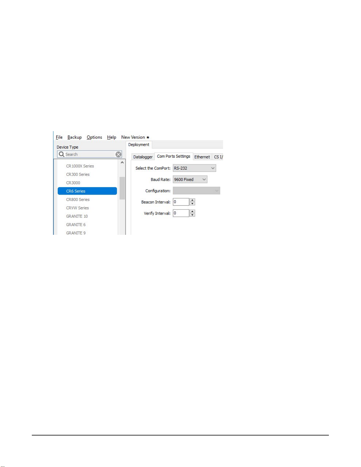
16. Click the Deployment tab.
17. Click the Com Port Settings sub tab.
18. Select 9600 for the Baud Rate.
19. Click Apply to save the changes.
Now the settings are stored in the data logger. CRBasic programming is required to push data
over the network. The GOESTable() and GOESField() CRBasic instructions used in
conjunction with DataTable() facilitate the transmission of data across the GOES satellite
network.
4.1 Data collection platform (DCP) installation
1. Yagi antenna installation procedure:
a. Mount the Yagi antenna to a pole or mast by using the U-bolts included with the
antenna mount.
b. Attach elements to boom.
TX326 Satellite Transmitter for METEOSAT 4
NOTE:
When attaching elements to the boom, make sure to place them such that the
number of grooves on the element equals the number of dimples on the boom.
For example, the element with four grooves should be placed at the spot on the
boom with four dimples, and so forth.
c. Aim the Yagi antenna at the spacecraft; azimuth and elevation angle positions are
included on the bracket label.
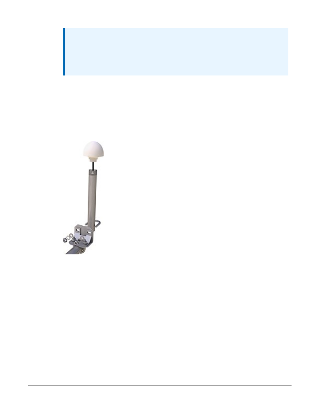
2. GPS antenna installation procedure:
a. Connect the GPS cable to the GPS antenna.
b. Route the cable through the 0.75-inch IPS threaded pipe and insert the pipe into the
GPS antenna.
TX326 Satellite Transmitter for METEOSAT 5
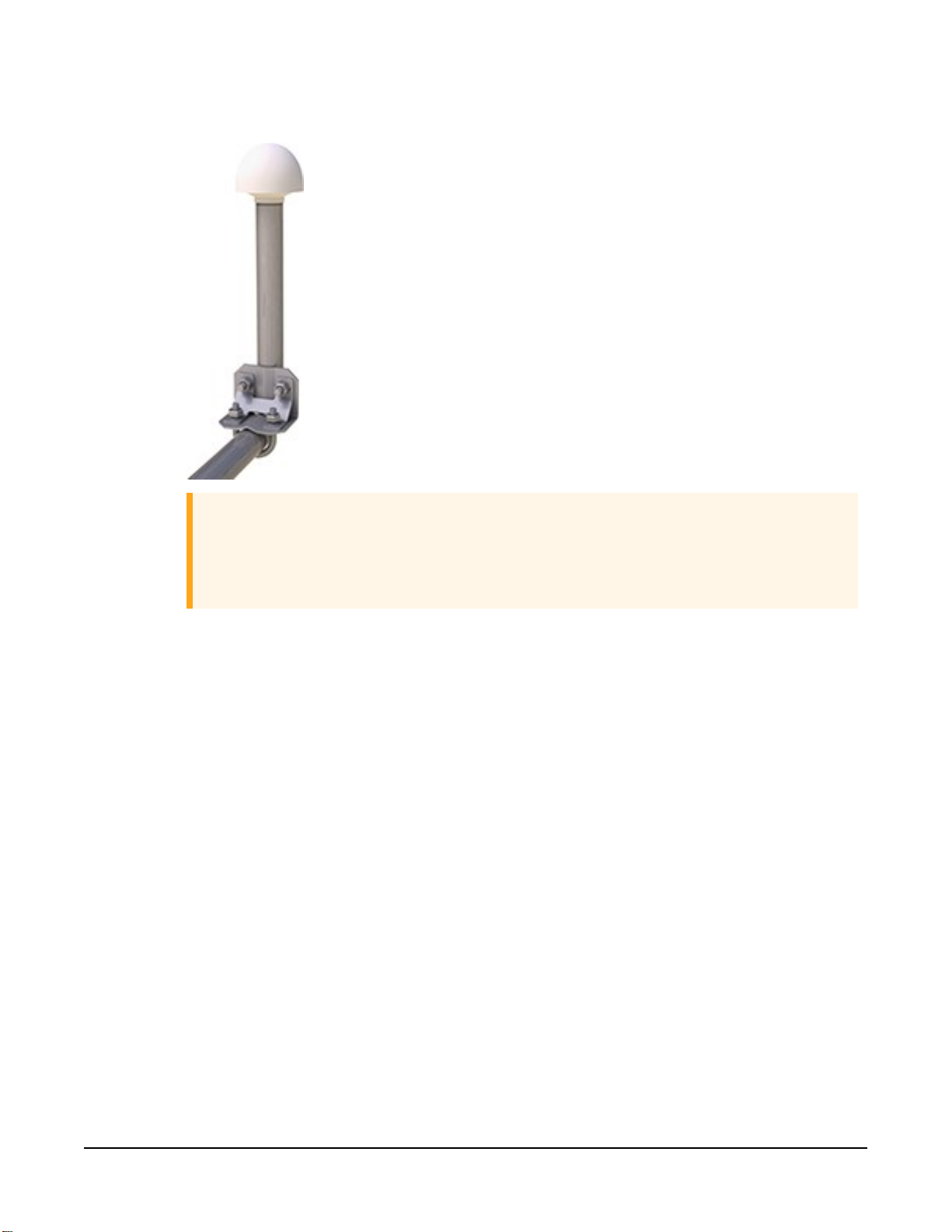
c. Mount the 0.75-inch IPS threaded pipe to a crossarm by using the Nu-Rail® fitting,
or CM220 mounting bracket.
CAUTION:
The GPS antenna will not receive a GPS signal through steel roofs or steel walls.
Concrete might also be a problem. Heavy foliage, snow, and ice will attenuate
the GPS signal.
3. Mount the TX326, the power supply, and the data logger to the backplate of an enclosure.
4. Mount the enclosure and solar panel to the pole or tripod.
TX326 Satellite Transmitter for METEOSAT 6
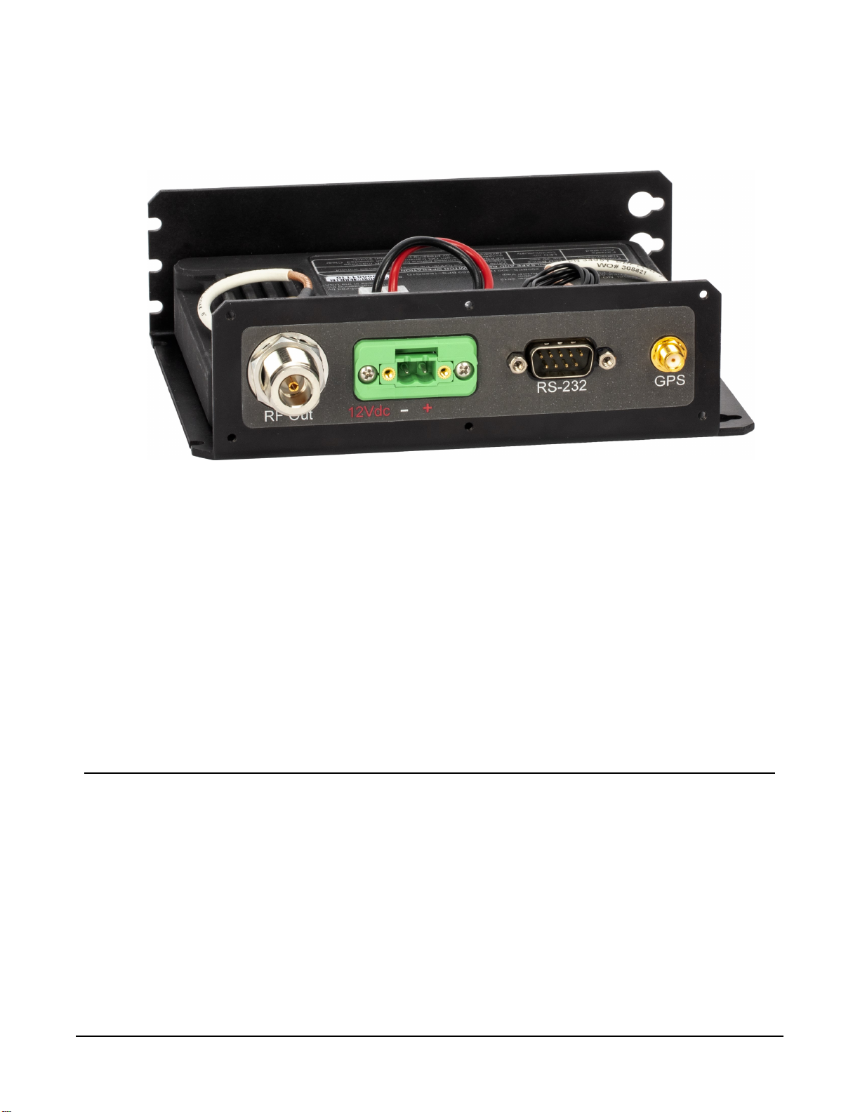
5. Connect the COAXNTN cable to the Yagi antenna. Route the COAXNTN cable through the
enclosure conduit and connect it to the RF Out connector on the TX326 (FIGURE 4-2 (p.
7)).
FIGURE 4-2. TX326 connectors
6. Route the GPS antenna cable through the enclosure conduit and connect it to the GPS
connector on the TX326 (FIGURE 4-2 (p. 7)).
7. Plug the green connector from the power supply to the green receptacle on the TX326.
8. Connect the data logger to the TX326 RS-232 terminal.
9. Route the solar panel cable through the enclosure conduit and connect the red and black
wires to the CHG terminals on the CH150 or CH200.
5. Overview
The TX326 can transmit either self-timed or random messages to the Meteosat/EuroSat satellites.
In a typical configuration, the TX326 is connected to a data logger via an RS-232 serial
connection. The data logger makes measurements, then formats those values to create a data
packet, which is transferred to the transmitter at time of transmission. The data logger buffers the
message until its transmission window (or random transmission time), then transmits the data.
Supported transmission rates are 100 (SRDCP) and 1200 (HRDCP) bps.
TX326 Satellite Transmitter for METEOSAT 7

GPS is required for the radio to work in the Meteosat/EuroSat network. All the radios in the
network must have exact timing of their transmissions so they don't step on each other during
transmissions. Extremely accurate timing is obtained from the integrated GPS receiver (±100 μs),
and the internal clock is capable of maintaining accurate time for a minimum of six days without
a GPS fix. If the TX326 finds itself without an accurate time, it suspends data transmissions until
an accurate time is obtained. The GPS time is synched every 11 hours. The data logger clock is
synched with the GPS time of the TX326.
Features:
l EUMETSAT SDR and HDR certified
l Based on Signal Engineering OmniSat3 design
l Compatible with Meteosat/EuroSat satellite data collection system
l Easy integration with Campbell Scientific data loggers
l Field tested and proven track record of reliability
l Embedded GPS receiver for stabilized internal time keeping and transmit frequency for
long service intervals
l Low standby current consumption for battery-powered systems at remote DCP installation
sites
l Quick assessment of radio health via monitoring of diagnostic data from the radio
l Compatible CRBasic data loggers: GRANITE series, CR6, CR1000X, and CR300 series
5.1 Meteosat/EuroSat system
Meteosat/EuroSat is a system of geostationary meteorological satellites operated by European
Organization for the Exploitation of Meteorological Satellites (EUMETSAT). Geostationary
satellites have orbits that coincide with the Earth's rotation, allowing each satellite to remain
above a specific region. FIGURE 5-1 (p. 9) shows the coverage of each satellite. EUMETSAT is an
intergovernmental organization created through an international convention of European
countries. For Meteosat DCP registration information, refer to:
www.eumetsat.int/website/home/Data/MeteosatDataCollectionServices/index.html.
TX326 Satellite Transmitter for METEOSAT 8
 Loading...