

Campbell Scientific TX325 User manual

Revision: 01/2021
Copyright © 2019 – 2021
Campbell Scientific, Inc.

Table of contents
1. Introduction 1
2. Precautions 1
3. Initial inspection 1
4. QuickStart 2
4.1 Data collection platform (DCP) installation 4
5. Overview 7
5.1 GOES, NESDIS, and transmit windows 8
6. Specifications 10
7. Installation 11
7.1 Field site requirements 11
7.2 LED function 12
7.3 Ports and connectors 13
7.4 Transmission antenna 14
7.5 GPS antenna 14
7.6 Data logger programming 14
7.6.1 Read and write settings 16
7.6.2 Read-only settings 17
8. Troubleshooting 19
8.1 Troubleshooting over-air transmissions 20
Appendix A. Eligibility and getting onto the GOES system 23
Appendix B. Data formats and transmission durations 24
B.1 ASCII data format 24
B.1.1 7-byte floating-point ASCII (GOESTable() format option 1) 24
B.1.2 ASCII table space (GOESTable() format option 2) 26
B.1.3 ASCII table space, comma separated (GOESTable() format option 3) 29
B.1.4 Line SHEF (Standard Hydrological Exchange Format) (GOESTable() format
option 6) 31
B.2 Pseudobinary data formats 32
Table of Contents - i

B.2.1 Campbell Scientific FP2 data 33
B.2.2 Pseudobinary 38
B.2.3 Additional pseudobinary representations 38
B.3 Transmission durations 38
Appendix C. Compliance documents and certificates 40
Table of Contents - ii

1. Introduction
The TX325 transmitter sends data via Geostationary Operational Environmental Satellites (GOES),
and is the successor to the TX321. In the Western Hemisphere, the TX325 is compatible for use
with NOAA GOES DCS with a coverage range including Canada, the United States of America,
and Mexico—as well as most countries in Central America and many South American countries.
The TX325 is the telemetry backbone for many data collection platforms (DCP) that use GOES.
The satellite transmitter can be integrated with a number of Campbell Scientific data loggers and
is an available communications option for many systems, serving a wide range of applications.
2. Precautions
l READ AND UNDERSTAND the Safety section at the back of this manual.
l Although the TX325 is rugged, it should be handled as a precision scientific instrument.
l A proper antenna connection is required before transmission occurs. Failure to use a
properly matched antenna cable and antenna may cause permanent damage to the radio
frequency (RF) amplifiers.
l The TX325 requires an active GPS antenna with a maximum gain of 25 dB. The TX325 will
supply 3.3 V to the active GPS antenna.
3. Initial inspection
l Upon receipt of the TX325, inspect the packaging and contents for damage. File damage
claims with the shipping company.
l Check the ships with list to ensure all components are received.
TX325 Satellite Transmitter for GOES V2 1

4. QuickStart
Use our Device Configuration Utility to enter the required National Environmental Satellite Data
and Information Service (NESDIS) information that is unique to each data collection platform
(DCP). This QuickStart is for the CR6 (≥OS 10), CR300-series (≥OS 10), CR1000X (≥OS 4), and
GRANITE-series (≥OS1) data loggers.
1. Connect the data logger RS-232 to the TX325 RS-232 connector and connect the data
logger to a power supply. Also ensure the TX325 has power.
2. Connect to the data logger using Device Configuration Utility.
a. Do the following to directly connect your data logger to the Device Configuration
Utility:
i. Use the USB cable to connect the data logger to the computer.
ii. Click your data logger model for the Device Type in the Device Configuration
Utility.
iii. Click Direct for the Connection Type.
iv. Select the COM port on the computer to which the data logger is connected.
v. Click Connect.
b. For data loggers on an IP connection, do the following to remotely connect with the
Device Configuration Utility:
i. Click your data logger model for the Device Type in the Device Configuration
Utility.
ii. Click IP for the Connection Type.
iii. Type the Server Address.
iv. Type the PakBus/TCP Password.
v. Click Connect.
3. Click the Settings Editor tab.
TX325 Satellite Transmitter for GOES V2 2
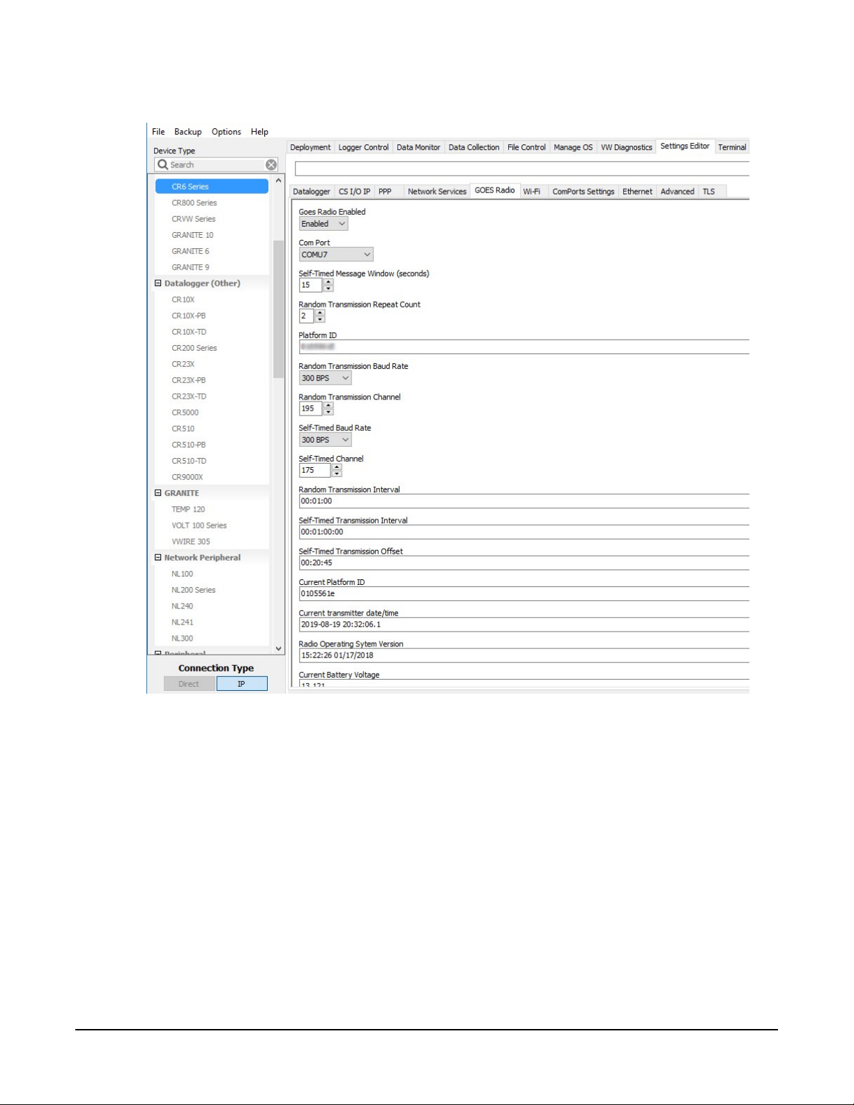
4. Click the GOES Radio sub tab (FIGURE 4-1 (p. 3)).
FIGURE 4-1. Device Configuration Utility GOES Radio screen
5. Select Enabled from the Goes Radio Enabled field.
6. Select the Com Port to which the GOES radio is connected.
7. Type the Self-timed Message Windows (in seconds) as assigned by the GOES DCS Program.
8. Type the Platform ID (in HEX) as assigned by the GOES DCS Program.
9. Select the Random Transmission Baud Rate as assigned by the GOES DCS Program.
10. Type the Random Transmission Channel as assigned by the GOES DCS Program.
11. Select the Self-Time Baud Rate as assigned by the GOES DCS Program.
TX325 Satellite Transmitter for GOES V2 3
12. Type the Self-Time Channel as assigned by the GOES DCS Program.
13. Type the Random Transmission Interval as assigned by the GOES DCS Program. Format is
hh:mm:ss.
14. Type the Self-timed Transmission Interval as assigned by the GOES DCS Program. Format is
dd:mm:hh:ss.
15. Type the Self-timed Transmission Offset as assigned by the GOES DCS Program. Format is
hh:mm:ss.
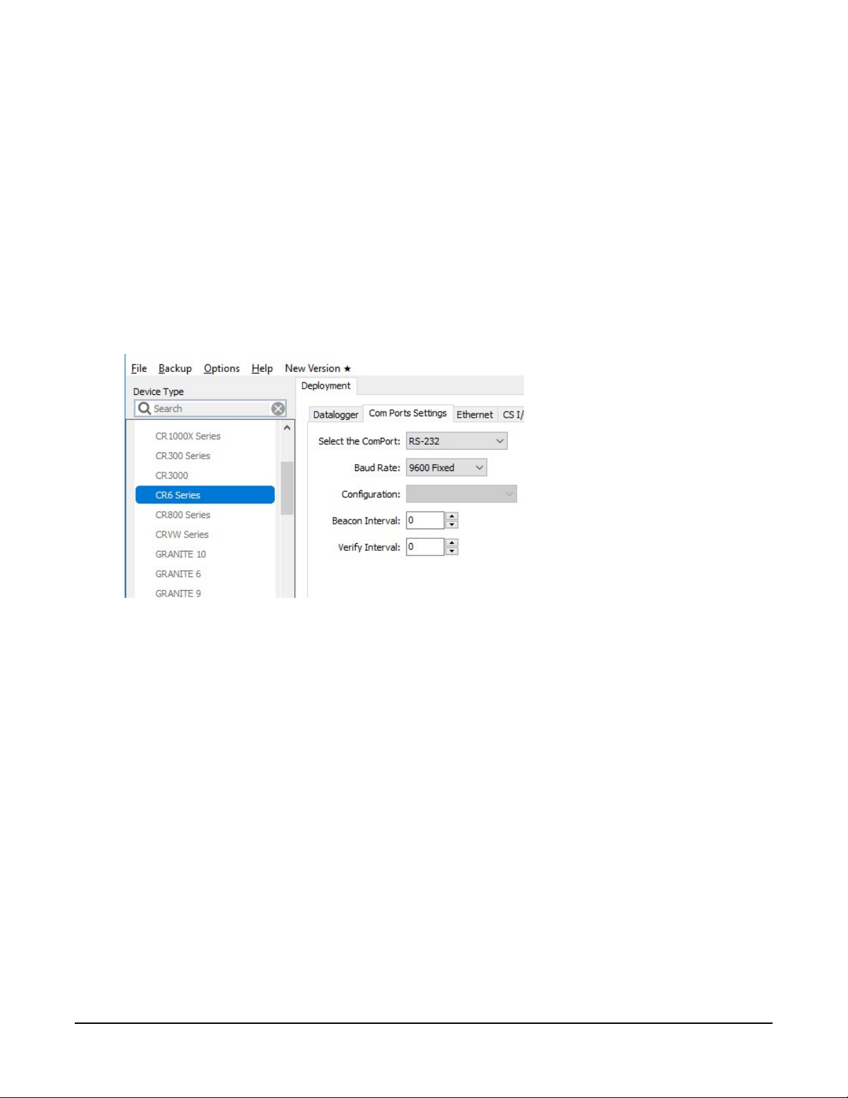
16. Click the Deployment tab.
17. Click the Com Port Settings sub tab.
18. Select 9600 for the Baud Rate.
19. Click Apply to save the changes.
Now the settings are stored in the data logger. CRBasic programming is required to push data
over the network. The GOESTable() and GOESField() CRBasic instructions used in
conjunction with DataTable() facilitate the transmission of data across the GOES satellite
network.
4.1 Data collection platform (DCP) installation
1. Yagi antenna installation procedure:
a. Mount the Yagi antenna to a pole or mast by using the U-bolts included with the
antenna mount.
TX325 Satellite Transmitter for GOES V2 4
b. Attach elements to boom.
NOTE:
When attaching elements to the boom, make sure to place them such that the
number of grooves on the element equals the number of dimples on the boom.
For example, the element with four grooves should be placed at the spot on the
boom with four dimples, and so forth.
c. Aim the Yagi antenna at the spacecraft; azimuth and elevation angle positions are
included on the bracket label.
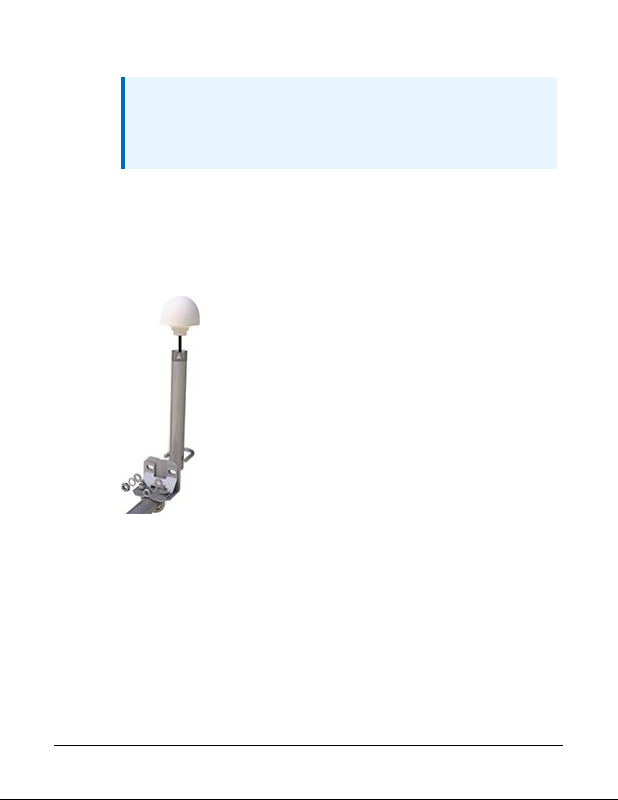
2. GPS antenna installation procedure:
a. Connect the GPS cable to the GPS antenna.
b. Route the cable through the 0.75-inch IPS threaded pipe and insert the pipe into the
GPS antenna.
TX325 Satellite Transmitter for GOES V2 5
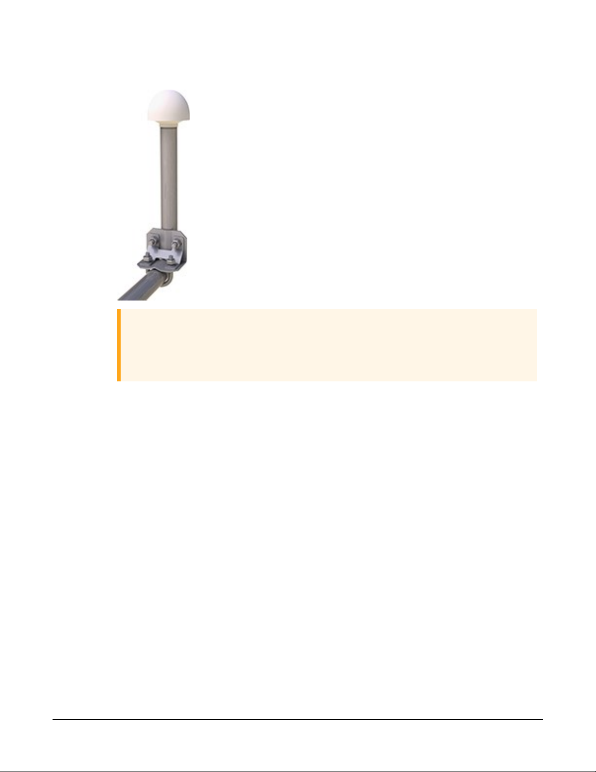
c. Mount the 0.75-inch IPS threaded pipe to a crossarm by using the Nu-Rail® fitting,
or CM220 mounting bracket.
CAUTION:
The GPS antenna will not receive a GPS signal through steel roofs or steel walls.
Concrete might also be a problem. Heavy foliage, snow, and ice will attenuate
the GPS signal.
3. Mount the TX325, the power supply, and the data logger to the backplate of an enclosure.
4. Mount the enclosure and solar panel to the pole or tripod.
TX325 Satellite Transmitter for GOES V2 6
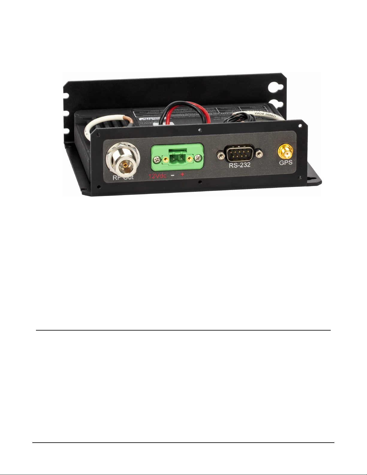
5. Connect the COAXNTN cable to the Yagi antenna. Route the COAXNTN cable through the
enclosure conduit and connect it to the RF Out connector on the TX325 (FIGURE 4-2 (p.
7)).
FIGURE 4-2. TX325 connectors
6. Route the GPS antenna cable through the enclosure conduit and connect it to the GPS
connector on the TX325 (FIGURE 4-2 (p. 7)).
7. Plug the green connector from the power supply to the green receptacle on the TX325.
8. Connect the data logger to the TX325 RS-232 terminal.
9. Route the solar panel cable through the enclosure conduit and connect the red and black
wires to the CHG terminals on the CH150 or CH200.
5. Overview
The TX325 can transmit either self-timed or random GOES messages to the GOES West and GOES
East satellites. In a typical configuration, the TX325 is connected to a data logger via an RS-232
serial connection. The data logger makes measurements, then formats those values to create a
data packet, which is transferred to the transmitter at time of transmission. The data logger
buffers the message until its transmission window (or random transmission time), then transmits
the data at either 300 or 1200 bps.
TX325 Satellite Transmitter for GOES V2 7

GPS is required for the radio to work in the GOES network. The GOES network is a TDMA
network that requires all the radios in the network to have exact timing of their transmissions so
they don't step on each other during transmissions. Extremely accurate timing is obtained from
the integrated GPS receiver (±100 μs), and the internal clock is capable of maintaining accurate
time for a minimum of six days without a GPS fix. If the TX325 finds itself without an accurate
time, it suspends data transmissions until an accurate time is obtained. The GPS time is synched
every 11 hours. The data logger clock is synched with the GPS time of the TX325 when using a
GRANITE-series, CR6, CR1000X-series, and CR300-series data logger.
Features:
l NESDIS HDR V2 certified
l Based on Signal Engineering OmniSat3 design
l Compatible with GOES DCS system
l Easy integration with Campbell Scientific data loggers
l Field tested and proven track record of reliability
l Embedded GPS receiver for stabilized internal time keeping and transmit frequency for
long service intervals
l Low standby current consumption for battery-powered systems at remote DCP installation
sites
l Quick assessment of radio health via monitoring of diagnostic data from the radio
l Compatible CRBasic data loggers: GRANITE series, CR6, CR1000X, and CR300 series are fully
compatible. The CR3000, CR800 series, and CR1000 have limited compatibility.
5.1 GOES, NESDIS, and transmit windows
GOES coverage area is latitude 68° North to 68° South and longitude 150° East to 2° West (see
FIGURE 5-1 (p. 9)). GOES satellites have orbits that coincide with the Earth rotation, allowing each
satellite to remain above a specific region (geosynchronous). GOES has two satellites: GOES East
located at 75° West longitude and GOES West located at 135° West longitude. Both satellites are
located over the equator. Within the United States, odd-numbered channels are assigned to
GOES East, and even-numbered channels are assigned to GOES West. Channels used outside of
the United States are assigned to either spacecraft.
TX325 Satellite Transmitter for GOES V2 8
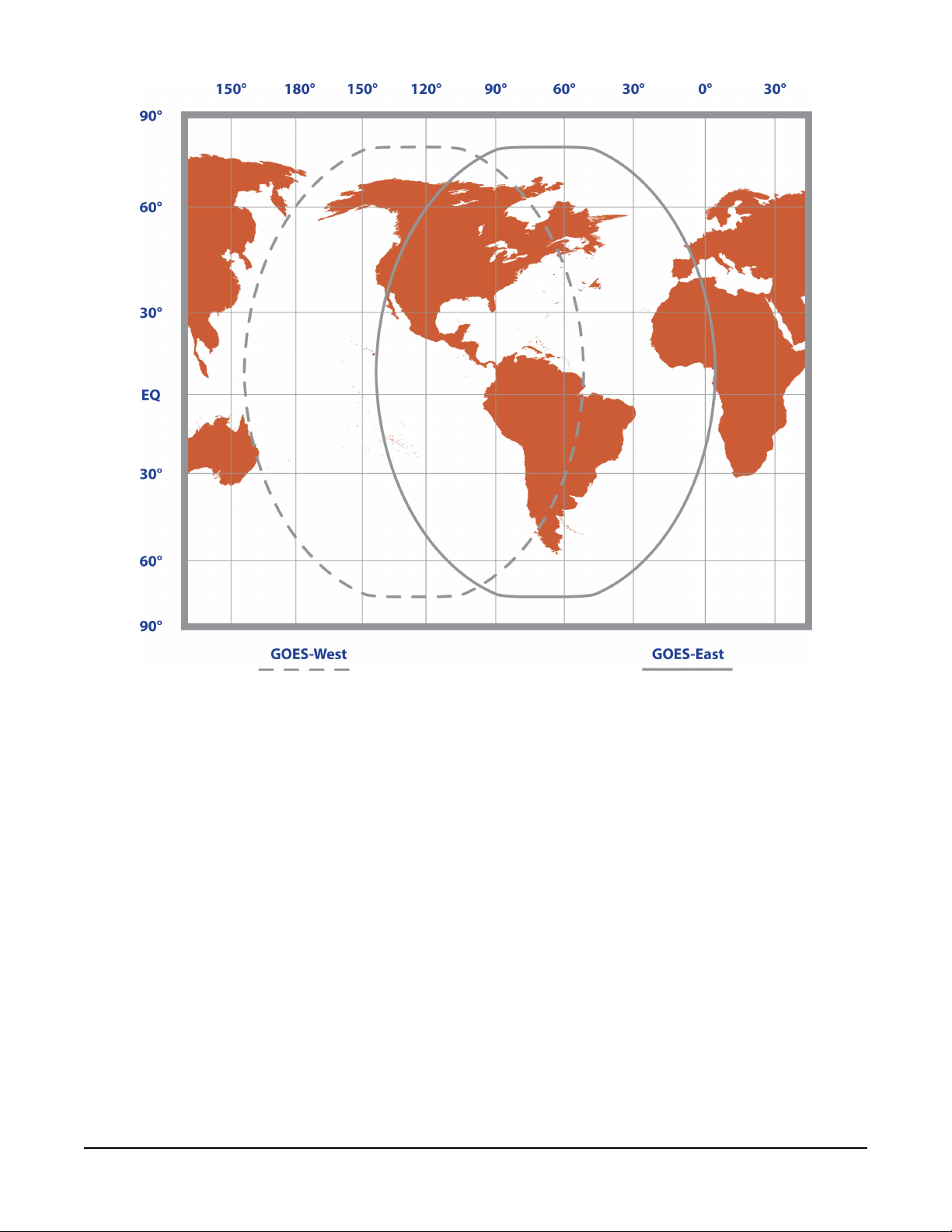
FIGURE 5-1. Coverage of GOES East and GOES West satellites
The GOES system is administered by the National Environmental Satellite Data Information
Service (NESDIS), which assigns addresses, uplink channels, and self-timed/random transmit time
windows. Self-timed windows allow data transmission only during a predetermined time frame
(typically 10 seconds every hour). Random windows are for applications of a critical nature, such
as flood reporting, and allow transmission immediately after a threshold has been exceeded. The
transmission is randomly repeated to ensure it is received. A combination of self-timed and
random transmission can be executed by the TX325.
Refer to Eligibility and getting onto the GOES system (p. 23) for more information.
TX325 Satellite Transmitter for GOES V2 9

6. Specifications
Compliance:
Transmissions supported:
Data formats: ASCII (SHEF),
Radio module:
Temperature range
Operating:
Storage:
Case dimensions
Without connectors:
With connectors:
Weight:
Supply voltage range:
Refer to
www.campbellsci.com/tx325
Timed (Scheduled), Random
OmniSat-3
–40 to 60 °C
–55 to 75 °C
15.88 x 12.7 x 4.57 cm (6.25 x 5 x 1.8 in)
15.88 x 14.99 x 4.57 cm (6.25 x 5.9 x 1.8 in)
additional clearance required for cables, wires, and antennas
0.77 kg (1.7 lb)
10.5 to 16 VDC
Compliance documents and certificates (p. 40)
and
pseudo binary
Current drain at 12 VDC
While transmitting: < 2.5 A
Standby:
During GPS acquisition: < 50 mA
Baud rates: 300
Transmit power
Maximum: 31 dBm (300 bps), 37 dBm
Maximum EIRP: 41 dBm (300 bps), 47 dBm
Typical EIRP: 37 to 41 dBm (300 bps)
Frequency range:
< 5 mA (2.8 typical)
11 dbm gain antenna with 1 dbm line loss
43 to 47 dBm
401.701 to 402.09925 MHz
(1.8 typical)
(25 mA typical)
and 1200 bps
(1200 bps)
(1200 bps)
(1200 bps); based on a
,
TX325 Satellite Transmitter for GOES V2 10

Initialfrequencystability:
±20 Hz disciplined to GPS (GPS fix occurs after power up and
once per day thereafter)
Channel bandwidth:
GPS receiver type:
Maximum GPS antenna RF
gain:
Timekeeping
Initial accuracy:
Drift:
GPS schedule:
Transmissioncontinuation
without GPS fix:
Interface connectors
RS-232:
Satellite RF transmit out:
GPS:
1500 Hz
3.3 V active
25 dB
±100 μs (synchronized to GPS)
±40 ms/day (without GPS)
1 fix at power up (updated at ~11-hour rate)
6 days
DB9 F, DCE, 3-wire RS-232
Type N jack
SMA jack
(300 bps), 2250 Hz (1200 bps)
Power:
2-pin screw terminal, 0.2 in. pitch
7. Installation
7.1 Field site requirements 11
7.2 LED function 12
7.3 Ports and connectors 13
7.4 Transmission antenna 14
7.5 GPS antenna 14
7.6 Data logger programming 14
7.1 Field site requirements
The GPS antenna must have a clear view of most of the sky and the transmission antenna must
have a clear view of the spacecraft. The TX325 must be installed in a well desiccated,
TX325 Satellite Transmitter for GOES V2 11
environmentally sealed enclosure. Its mounting plate has keyholes for securing the TX325 to the
backplate of a Campbell Scientific enclosure. Most GOES systems are powered by a battery
charged by a solar panel. The solar panel must have a clear view of the southern sky. Pay special
attention to winter sun angles.
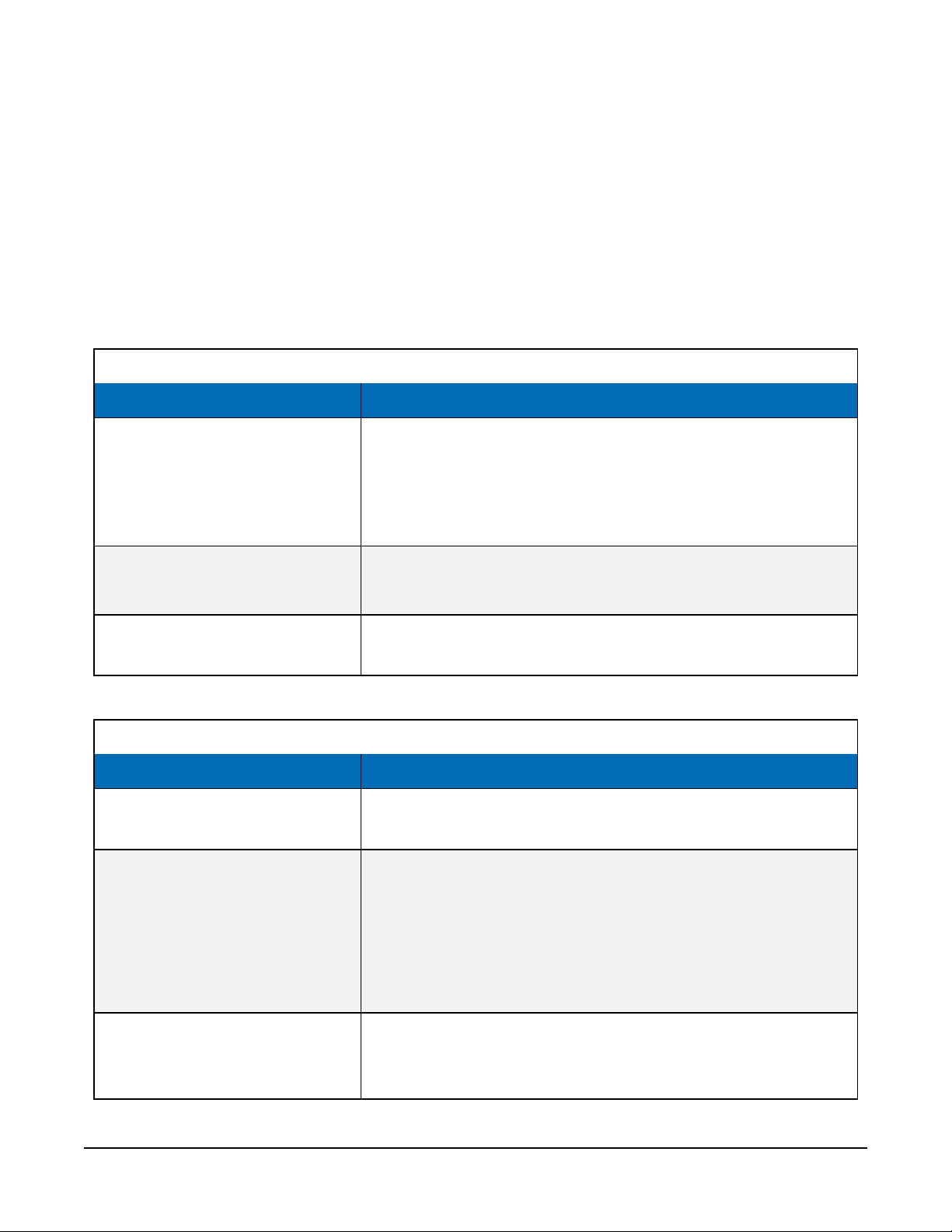
7.2 LED function
A green Status LED and a red Failsafe LED indicate the state of the TX325 transmitter by using
various blink patterns. Table 7-1 (p. 12) and Table 7-2 (p. 12) provide the blink patterns for the
green Status and red Failsafe LEDs, respectively.
Table 7-1: Green LED Status indicator blink patterns
Blink pattern Indicates
Normal software is running.
At power up, blinks on and off
two times.
At power up, blinks on and off
three times.
On continuously.
Table 7-2: Red LED Failsafe indicator blink patterns
Blink pattern Indicates
Blinks on and off four times per
second.
Blinks on and off two times per
second for 30 s.
RS-232 control interfaces enabled.
Power-up initialization complete and ready to receive
commands.
Bootloader software is running.
Ready to load new operating system.
Transmitter failed to start up normally after power up. Turn
the transmitter off and on to reboot.
A transmission is in progress.
The post-transmit interval is in progress. The transmitter
enters this state after its RF output is turned off either by a
Reset command or by the normal completion of a data
message transmission. The radio needs to wait 30 seconds
before making another transmission to keep it from going
into Failsafe mode.
On continuously.
TX325 is in the Failsafe mode. To clear a Failsafe mode, push
the Reset button (FIGURE 8-1 (p. 20)). A power cycle will NOT
clear the Failsafe mode.
TX325 Satellite Transmitter for GOES V2 12
 Loading...