

Page 1

TD OPERATING SYSTEM ADDENDUM FOR CR510, CR10X,
AND CR23X MANUALS
COPYRIGHT
REVISION: 1/03
2002-2003 CAMPBELL SCIENTIFIC, INC.
Page 2

This is a blank page.
Page 3

TABLE DATA ADDENDUM
TD and PakBus Operating System Addendum for
CR510, CR10X, and CR23X Manuals
AD1 Major Differences
Table Data (TD) operating systems have two major differences from the
standard operating systems: First - t he namesake - in the way data are
stored internally and second, in the options available for transferring
that data to external devices. The standard operating systems support
both on site external storage (i.e., storage modules) that may be
manually retrieved and telecommunications. The TD operating systems
have more advanced telecommunication and networking capabilities but
do not support storage modules. There are two versions of the TD
operating system: TD and PakBus. The PakBus operating system
includes the PakBus communications protocol that allows some
additional communications options (Section 12); other features are the
same as the TD operating system.
The datalogger hardware and direct measurement capabilities are the
a
me in either case.
s
Feature Table Data OS Standard OS
Internal Data Storage Multiple Data Tables, at least
one Table for each output
interval.
Term for a set of values output
together
Term for individual values
within the array or record
Number of elements or fields in
an array or record
Conditional Output Yes Yes
TimeStamps Automatic Optional
At Site / Manual Data Transfer No Yes
Storage Module Support No Yes
Instruction 96 – Serial Output No Yes
Instruction 98 – Send Character No Yes
Telecommunications Commands protocol with error
Error Checking for data Yes Yes
Confirmation for Commands Yes No
Data Advise – data automatically
sent (speeds mu lti-hop RF)
PakBus packet switching. Yes – in PakBus No
Supports Wireless Sensor Yes – in PakBus No
Support for Satellite
Transmitters
Analog Measurements No Difference No Difference
Pulse Measurements
Record (a row of the table) Array
Field (a column of the table) Element
A fixed number, determined by
the program
checking on all commands and
responses. Feedback to confirm
commands have been accepted.
Yes No
No Yes
No Difference No Difference
One or two Final Storage Areas.
Data A
rrays output at different
intervals may share the same area
and are identified by ID.
Generally fixed but conditional
elements possible. Determined
by program
Simple commands with error
ch
ecking on data sent from
datalogger to computer
AD-1
Page 4

TABLE DATA ADDENDUM
AD2 Overview of Data Storage Tables
Within a data table, data is organized in records and fields. Each row in a
table represents a record and each column represents a field. To
understand the concept of tables it may be helpful to consider an example.
A CR10-TD is to be used to monitor 3 thermocouples (TC). Each hour a
temperature for each of the three TC is to be stored. The table has 4 fields
: "DATE_TIME TEMP1 TEMP2 TEMP3". Each hour a new "record"
would be added. The "hourly" table would then be organized as follows:
DATE_TIME TEMP1 TEMP2 TEMP3
01/27/91 10:00:0023.5 24.6 28.2
01/27/91 11:00:0024.2 22.4 23.4
Only the hourly data is stored in the hourly table, Each output interval
s its own table. Data tables can also be "event driven" rather than
ha
interval driven, that is a new record is stored when a specified event
occurs rather than based on time. Each table is completely independent
of any other tables and all records in a given table have the same
number of fields.
The TD operating system supports naming of tables and fields, so any
a
lue can be referenced by the table and field names. For example,
data v
the temperature data for the first thermocouple is referenced as
"HOURLY.TEMP1". Computer software also allows the station to be
named. When multiple dataloggers are in use, this can be used to
reference specific data in the network. If, in the previous example, the
CR10T site was named DALLAS, the first thermocouple's data values
would be referenced by "DALLAS.HOURLY.TEMP1".
AD3 Converting an existing program to Table Based OS
This section is intended for those familiar with programming an Array
based datalogger.
AD3.1 Programming changes
• Remove all Record Real Time instructions (Instruction 77).
• Remove all Serial Data Output and Serial Print instructions
(Instructions 96 and 98).
• Remove all Initiate Telecommunication (callback) instructions
(Instruction 97).
• Check all instructions which set the Output Flag (Flag 0). These
should be replaced with the Data Table Instruction (Instruction 84).
If the Set Active Storage Area instruction (Instruction 80) is used, it
should be removed as Instruction 84 provides this functionality.
• Check all If Time Instructions (Instruction 92) as the units may
change from minutes to seconds. Any instruction 92 that sets the
output flag (Flag 0) is replaced by Instruction 84.
• Check the Move Time To Input Location Instruction (Instruction
18) as some parameters have changed.
AD-2
Page 5

Check the Maximum and Minimum Instructions ( Instructions 73
•
and 74) as there is only one option to store time with the value.
• Edit Input Location labels removing all spaces and special
characters. Only letters, numbers, and the “_” characters are
allowed. Labels should start with a letter.
• Add labels for the Final Storage values. Use the same character as
are allowed for Input Location labels. See Section 2.1
AD3.2 Making the Changes with Edlog
Programs for Array based logger can be converted to Table Based using
EDLOG for most of the editing by doing the following:
1. Make a copy of the original program with the name you want the
new program to have: Load the original into Edlog and “Save As”
the new name .
2. Remove or comment out all Instructions 77, 96, 97, and 98. (first
three points in AD3.1, these instructions are not in the Table OS)
TABLE DATA ADDENDDUM
3. Save the edited program and close it in Edlog.
4. Edit the CSI file with a text editor (e.g., “Notepad” - Edlog will not
allow you to make and save this change) and add –TD to the
datalogger type on the first line, for example, change:
;{CR10X}
to:
;{CR10X-TD}.
Save the CSI file and close the editor.
5. Open the file with Edlog. Edlog should now recognize that the
program is for a table data OS.
6. Add Instructions 84 where necessary and make the other necessary
changes.
AD-3
Page 6

TABLE DATA ADDENDUM
AD4 Summary of Differences from the Datalogger Manual:
Section
Overview
Section 1
Section 2
Section 3
Section 4
Section 5
Section 6
Section 7
Section 8
Section 9
Section 10
Section 11
Differences
Figure OV2.1-2: See Figure 1.5-1 in Addendum.
Table OV3.2-1: See Table OV4.1-1 in TD Addendum.
OV4, OV5, OV6 :See TD Addendum.
Section 1.5 A Mode is replaced by addendum – the TD loggers
allocate memory differently.
Section 1.8 - *D Mode is replaced by TD Addendum – TD loggers do
not support storeing multiple programs or Storage Modules. PakBus
Settings are added to the *D Mode.
Replaced entirely by TD Addendum.
Section 3.7.1 does not apply to the TD operating system which does
not use Output Flag 0.
Table 3.8-1 Valid Flag Commands are 11 – 19 to set high and 21- 29
to set Low. Because the TD operating system does not use Flag 0,
Commands 10 and 20 are not valid with the TD operating system.
Table 3.10-1 TD Addendum. has a corrected version
Does not apply: The TD operating system does not support External
Storage Peripherals.
Does not apply: The communications commands and protocol of the
TD operating system is different than that of the standard operating
systems. Campbell Scientific provides software for communications;
a description of the protocol is beyond the scope of this addendum.
Many of the peripherals discussed in section 6 are not supported by
the TD operating system.
No Change
Replaced entirely by TD Addendum.
Instruction 18 has some differences in the time options, see
addendum.
No Change
Instructions 73 and 74 have only one option for storing the time of
max or min (time is output as a quoted string).
AD-4
Instruction 80 – Set Active Storage Area, is not in the TD o perating
system. Its functions are included in Instruction 84 – Data Table.
Instruction 84 – Data Table, sets the conditions and destination for
output data. This instruction is only in the TD operating system (see
TD Addendum..)
Page 7

TABLE DATA ADDENDDUM
Section 12
Section 13 No Change
Section 14 No Change
The TD operating system does not use the output Flag 0.
Commands dealing with it are not valid.
Instruction 92 – There is no option for minutes, time is in seconds
only.
Instructions Not In TD OS:
struction 96 – Serial Output
In
Instruction 98 – Send Character
n
struction 111 – Load Program from Flash
I
New Instructions for PakBus:
Instruction 190 – Send or Get Input Locations
Instruction 191 – One way Final Storage Data Transfer
Instruction 192 – PakBus Message
Instruction 193 – Wireless Network Master Control
Instruction 194 – Time Until Transmit
Instruction 195 – Set Clock from Address
Instruction 196 – Wireless Remote
Instruction 197 – Force Route Through Address
AD-5
Page 8

TABLE DATA ADDENDUM
This is a bla nk page.
AD-6
Page 9

MEASUREMENT AND CONTROL MODULE OVERVIEW
While this section of the addendum references the CR10X, everything but the measurement instructions
in the example programs applies to the other dataloggers as well.
Table OV3.2-1 in the CR10X Manual is incorrect for the TD operating system. See Tabl
The following sections OV4, OV5, and OV6 replace those in the CR10X Manual.
OV4. PROGRAMMING THE CR10X
A program is created by entering it directly into
the datalogger or into a computer using the
LOGGERNET program EDLOG. This manual
describes direct interaction with the CR10X.
Work through the direct programming examples
in this overview before using EDLOG and you
will know the basics of CR10X operation as well
as an appreciation for the help provided by the
software. Section OV4.5 describes options for
loading the program into the CR10X.
OV4.1 FUNCTIONAL MODES
CR10X/User interaction is broken into different
tional MODES (e.g., programming the
unc
f
measurements and output, setting time, etc.).
The modes are referred to as Star (*) Modes
since they are accessed by first keying *, then
the mode number or letter. Table OV4.1-1 lists
the CR10X Modes.
OV4.2 KEY DEFINITION
Keys and key sequences have specific functions
ing the CR10KD keyboard or a computer
hen us
w
in the remote keyboard state (Section 5). Table
OV4-2 lists these functions. In some cases, the
exact action of a key depends on the mode the
CR10X is in and is described with the mode in the
manual.
TABLE OV4.1-1. * Mode Summary
Key Mode
*0 LOG data and indicate active Tables
*1 Program Table 1
*2 Program Table 2
*3 Program Table 3, subroutines only
*5 Display/set real time clock
*6 Display/alter Input Storage data,
toggle fl
*7 Display Data Storage Table data
*9 Display Data Storage Table sizes
*A Memory allocation/reset
*B Signature/status
*C Security
TABLE OV4.2-1. Key Description/Editing
Key Action
0-9 Key numeric entries into display
* Enter Mode (followed by Mode
Number
A Enter/Advance
ags and ports
Functions
)
e OV4.1-1 below.
When using a computer/terminal to
municate with the CR10X
om
c
(Telecommunications) there are some keys
available in addition to those found on the
CR10KD. Table OV4.2-2 lists these keys.
B Back up
C Change the sign of a number or index
an input location to loop c
D Enter the decimal point
# Clear the rightmost digit keyed into
the disp
#A Advance to next instruction in
progr
#B Back up to previous instruction in
progr
#D Delete entire instruction
lay
am table (*1, *2, *3)
am table.
ounter
AD-OV-1
Page 10

TD ADDENDUM—OVERVIEW
TABLE OV4.2-2. Additional Keys Allowed in
Telecommunications
Key Action
- Change Sign, Index (same as C)
CR Enter/advance (same as A)
OV4.3 PROGRAMMING SEQUENCE
In routine applications, the CR10X measures
sens
or output signals, processes the
measurements over some time interval and
stores the processed results. A generalized
programming sequence is:
1. Enter the execution interval. In most cases,
ution interval is determined by the
ec
the ex
desired sensor scan rate.
2. Enter the Input/Output instructions required
to meas
3. If processing in addition to that provided by
the Output Pr
is required, enter the appropriate
Processing Instructions.
4. Enter the Data Table Instruction 84 to test
the output c
condition is met. For example, use
This instruction must precede the Output
Proc
a Data Storage Table. Instructions are
described in Sections 9 through 12.
5. Enter the Output Processing Instructions to
t
s
Table. The order in which data are stored
is determined by the order of the Output
Processing Instructions in the table.
6. Repeat steps 4 through 6 for additional
outputs
ure the sensors.
ocessing Instructions (step 5)
ondition and output w
Instruction 84 to output based on time.
Instruction 84 to output every execution
al.
interv
Instruction 84 to output based on a
am Flag.
Progr
essing Instructions which store data in
ore processed data in the Data Storage
ferent intervals or conditions.
on dif
hen the
NOTE: The program must be executed for
output to occur. Therefore, the interval
specified with the Data Table Instruction is
set must be evenly divisible by the execution
interval. For example, with a 2 minute
execution interval and a 5 minute output
interval, the program will only be executed
on the even multiples of the 5 minute
intervals, not on the odd. Data will be output
every 10 minutes instead of every 5 minutes.
Execution intervals are synchronized with
midnight. Output intervals set with Instruction
84 are synchronized with real time starting at
midnight, January 1, 1990.
OV4.4 INSTRUCTION FORMAT
Instructions are identified by an instruction
ber
num
parameters that give the CR10X the information
it needs to execute the instruction.
The CR10X Prompt Sheet has the instruction
num
listed in columns following the description.
Some parameters are footnoted with further
description under the "Instruction Option Codes"
heading.
For example, Instruction 73 stores the
m
Storage location over the output interval. The
instruction has three parameters (1)
REPetitionS, the number of sequential Input
Storage locations on which to find maxima, (2)
TIME, an option of storing the time of
occurrence with the maximum value, and (3)
LOC the first Input Storage location operated on
by the Maximum Instruction. The codes for the
TIME parameter are listed in the "Instruction
Option Codes".
The repetitions parameter specifies how many
tim
For example, four 107 thermistor probes may be
measured with a single Instruction 11, Temp-107,
with four repetitions. Parameter 2 specifies the
input channel of the first thermistor (the probes
must be connected to sequential channels).
Parameter 4 specifies the Input Storage location in
which to store measurements from the first
thermistor. If location 5 were used and the first
probe was on channel 1, the temperature of the
thermistor on channel 1 would be stored in input
. Each instruction has a number of
ber
s in red, with the parameters briefly
ax
imum value that occurred in an Input
an instruction's function is to be repeated.
es
AD-OV-2
Page 11

TD ADDENDUM—OVERVIEW
location 5, the temperature from channel 2 in input
location 6, etc.
Detailed descriptions of the instructions are
given in Sect
into a program table is described in OV5.
OV4.5 ENTERING A PROGRAM
Programs are entered into the CR10X in one of
ays:
o w
tw
1. Keyed in using the CR10X keyboard
2. Stored on disk/seat from computer
A program is created by keying it directly into
the datalogger
on a PC using EDLOG.
EDLOG is used to develop programs for
pbell Sc
Cam
EDLOG is a prompting editor for writing and
documenting programs for Campbell Scientific
CR10X dataloggers. Program files developed
with EDLOG can be downloaded directly to the
CR10X using NetAdmin. NetAdmin supports
communication via direct wire, telephone, or
Radio Frequency (RF).
ions 9-12. Entering an instruction
as
described in Section OV5, or
ientific CR10X dataloggers.
OV5. PROGRAMMING EXAMPLES
We will start with a simple programming
example. There is a brief explanation of each
step to help you follow the logic. When the
example uses an instruction, find it on the
Prompt Sheet and follow through the
description of the parameters. Using the
Prompt Sheet while going through these
examples will help you become familiar with its
format. Sections 9-12 have more detailed
descriptions of the instructions.
With the Wiring Panel connected to the CR10X,
up the pow
hook
Section OV1.2. Next, connect the CR10X to
either a CR10KD Keyboard/Display or the
computer (Section OV3). The programming
steps in the following examples use the
keystrokes possible on the keyboard/display.
With a terminal, some responses will be slightly
different.
If the CR10KD is connected to the CR10X when
ered up, the display will show:
pow
it is
Display Explanation
HELLO On power-up, the CR10X
after a few seconds delay
:96 The size of the machine's total
OV5.1 SAMPLE PROGRAM 1
In this example the CR10X is programmed to
own internal temperature (using a built
ead its
r
in thermistor) every 5 seconds and to send the
results to Final Storage.
er leads as described in
displays "HELLO" while it checks
the memory (this display occurs
only with the CR10KD).
ory (RAM plus 32 K of
em
m
ROM), in this case 96K
Key Display Explanation
* 00:00 Enter mode.
1 01:00 Enter Program Table 1.
A 01:0.0000 Advance to execution interval (In seconds)
5 01:5 Key in an execution interval of 5 seconds.
A 01:P00 Enter the 5 second execution interval and advance to
i
rst program instruction location.
the f
17 01:P17 Key in Instruction 17 which directs the CR10X to
eas
ure the internal temperature in degrees C. This is
m
an Input/Output Instruction.
A 01:0000 Enter Instruction 17 and advance to the first parameter.
1 01:1 The input location to store the measurement, location 1.
A 02:P00 Enter the location # and advance to the second
am instruction.
ogr
pr
The CR10X is now programmed to read the internal temperature every 5 seconds and place the reading
in Input Storage Loc
ation 1. The program can be compiled and the temperature displayed.
AD-OV-3
Page 12

TD ADDENDUM—OVERVIEW
Key (ID:Data) Explanation
*0 LOG 1 Exit Table 1, enter *0 Mode, compile table and begin
*6 06:0000 Enter *6 Mode (to view Input Storage).
A 01:21.234 Advance to first storage location. Panel temperature is
Wait a few seconds:
*1 01:00 Exit *6 Mode. Enter program table 1.
2A 02:P00 Advance to 2nd instruction location (this is where we
84 02:P84 This is the Data Table Instruction.
A 01:0.0000 Enter 84 and advance to the first parameter (which is
0 01:0 This parameter determines when in the output internal
A 02:0.000 Enter 0 and advance to the second parameter.
0 02:0 This parameter specifies the output interval. 0 stores
A 03:0.0000 Enter 0 and advance to third parameter.
1000 03:1000.00 This parameter specifies how many records to store in
A 03:P00 Enter 1000 and advance to the third program
70 03:P70 The SAMPLE instruction. It directs the CR10X to take
A 01:0000 Enter 70 and advance to the first parameter
1 01:1 There is only one input location to sample; repetitions = 1.
A 02:0000 Enter 1 and advance to second parameter (Input
1 02:1 Input Storage Location 1, where the temperature is
A 04:P00 Enter 1 and advance to fourth program instruction.
* 00:00 Exit Table 1.
0 LOG 1 Enter *0 Mode, compile program, log data.
logging.
the display will show the actual
21.234°C
temperature).
01:21.423 The CR10X has read the sensor and stored the result
again. The inter
is updated every 5 seconds when the table is executed.
At this point the CR10X is measuring the temperature
every 5 seconds and sending the value to Input
Storage. No data are being saved. The next step is to
have the CR10X send each reading to Final Storage.
ft off).
e
l
the tim
data is
data eac
the table bef
example, keep 1000 records.
struction.
n
i
a r
Final Storage (an Output Processing Instruction).
epetitions).
r
(
Stor
t
ored.
s
(
nal temp is now 21.423°C. The value
into the interval).
e
s
tored. 0 stores data on the even interval.
ecution.
h ex
e overwriting the oldest. For this
or
eading f
rom an Input Storage location and send it to
age loc
ation to sample).
AD-OV-4
Page 13

TD ADDENDUM—OVERVIEW
OV5.2 SAMPLE PROGRAM 2
This second example is more representative of a
real-
life data collection situation. Once again the
internal temperature is measured, but it is used
as a reference temperature for the differential
voltage measurement of a type T (copperconstantan) thermocouple; the CR10X should
have arrived with a short type T thermocouple
connected to differential channel 5.
When using a type T thermocouple, the copper
blue)
lead (
differential channel, and the constantan lead
(red) is connected to the low input.
A thermocouple produces a voltage that is
opor
pr
between the measurement and the reference
junctions.
To make a thermocouple (TC) temperature
eas
m
junction (in this example, the approximate panel
temperature) must be measured. The CR10X
takes the reference temperature, converts it to
the equivalent TC voltage relative to 0°C, adds
the measured TC voltage, and converts the
sum to temperature through a polynomial fit to
the TC output curve (Section 13.4).
The internal temperature of the CR10X is not a
uitable r
s
thermocouple measurements. It is used here
for the purpose of training only. To make
thermocouple measurements with the CR10X,
purchase the Campbell Scientific Thermocouple
Reference, Model CR10XCR (Section 13.4) and
make the reference temperature measurement
with Instruction 11.
Instruction 14 directs the CR10X to make a
erential TC temperature measurement. The
f
dif
first parameter in Instruction 14 is the number of
times to repeat the measurement. Enter 1,
because in this example there is only one
thermocouple. If there were more than 1 TC,
they could be wired to sequential channels, and
the number of thermocouples entered for
repetitions. The CR10X would automatically
advance through the channels sequentially and
measure all of the thermocouples.
is connected to the high input of the
tional to the difference in temperature
urement, the temperature of the reference
eference temperature for precision
per degree C difference in temperature between
the two junctions. The ±2.5 mV scale will
provide a range of ±2500/40 = ±62.5°C (i.e.,
this scale will not overrange as long as the
measuring junction is within 62.5°C of the panel
temperature). The resolution of the ±2.5 mV
range is 0.33 µV or 0.008°C.
Parameter 3 is the analog input channel on
hic
h to make the first, and in this case only,
w
measurement. Parameter 4 is the code for the
type of thermocouple used. This information is
located on the Prompt Sheet or in the
description of Instruction 14 in Section 9. The
code for a type T (copper-constantan)
thermocouple is 1.
Parameter 5 is the Input Storage location in
hic
h the reference temperature is stored.
w
Parameter 6 is the Input Storage location in
which to store the measurement (or the first
measurement; e.g., if there are 5 repetitions
and the first measurement is stored in location
3, the final measurement will be stored in
location 7). Parameters 7 and 8 are the
multiplier and offset. A multiplier of 1 and an
offset of 0 outputs the reading in degrees C. A
multiplier of 1.8 and an offset of 32 converts the
reading to degrees F.
In this example, the sensor is measured once a
i
nute, and the average temperature is output
m
every hour. Once a day the maximum and
minimum temperatures and the times they occur
will be output.
The first example described program entry one
ey
stroke at a time. This example does not
k
show the "A" key. Remember, "A" is used to
enter and/or advance (i.e., between each line in
the example below). This format is similar to
the format used in EDLOG.
It's a good idea to have both the manual and the
pt Sheet handy when going through this
om
Pr
example. You can find the program instructions
and parameters on the Prompt Sheet and can
read their complete definitions in the manual.
To obtain daily output, the Data Table
t
ruction is followed by the Output Instructions
ins
to store the daily maximum and minimum
temperatures and the time each occurs.
Parameter 2 is the voltage range to use when
ing the measurement. The output of a type
ak
m
T thermocouple is approximately 40 microvolts
AD-OV-5
Page 14

TD ADDENDUM—OVERVIEW
Instruction # Parameter
(Loc:Entry) (Par#:Entry) Description
*1 Enter Program Table 1
01:60 60 second (1 minute) execution interval
Key "#D"
repeatedly
is displayed
01:P17 Measure internal temperature
02:P14 Measure thermocouple temperature (differential)
until 01:P00 Erase previous Program before continuing.
SAMPLE PROGRAM 2
S
01:1
01:1 1 repetition
02:1 Range code (2.5 mV, slow)
03:5 Input channel of TC
04:1 TC type: copper-constantan
05:1 Reference temp is stored in Location 1
06:2 Store TC temp in Location 2
07:1 Multiplier of 1
08:0 No offset
tore temp in Location 1
03:P84 Data Table Instruction
0 s
01:0
02:3600 3600 second (60 min.) internal
03: 0 Automatically allocate # of records
The CR10X is programmed to measure the thermocouple temperature every sixty seconds.
he CR10X automatic
T
stored. Next the output instruction for the average is added.
Instruction # Parameter
(Loc.:Entry) (Par.#:Entry)
04:P71 Average instruction
05:P84 Data Table Instruction
06: P73 Maximize instruction
07: P74 Minimize instruction
ally allocates the number of records. Time information is automatically
01:1 One repetition
02:2 Location 2 - source of TC temps. to be averaged
01:0 0 seconds into the interval
02:86400 86400 second interval (24 hrs.)
03:0 Automatically allocate # of records
01:1 One repetition
02:1 Output the time of the daily maximum
03:2 Data source is Input Storage Location 2.
01:1 One repetition
02:1 Output the time of the daily minimum
03:2 Data source is Input Storage Location 2.
econds into the interval
Description
AD-OV-6
Page 15

TD ADDENDUM—OVERVIEW
The program to make the measurements and send the desired data to Final Storage has been
ed. T
enter
are correct. (Here the example reverts back to the key by key format.)
Key Display Explanation
*5 00:21:32 Enter *5 Mode. Clock running but not set correctly.
A 05:01.01 Advance to month-day (MMDD).
1004 05:1004 Key in MMDD (Oct 4 in this example).
A 05:1990 Enter and advance to location for year.
1994 05:1994 Key in year.
A 05:00:21 Enter and advance to location for hours and minutes
1324 05:1324 Key in hrs.:min. (1:24 PM in this example).
A 05:27.250 Key in seconds
30 05:30
A 13:24:30 Clock set and running. Changes made when A was
he program is complete. The clock must now be set so that the date and time tags
. time).
(24 hr
sed.
pres
*0 LOG 1 Exit *5, compile Table 1, commence logging data.
OV5.3 EDITING AN EXISTING PROGRAM
When editing an existing program in the
CR10X, enter
instruction; entering a new parameter replaces
the previous value.
To insert an instruction, enter the program table
and advanc
instruction is to be inserted (i.e., P in the data
portion of the display) key in the instruction
number, and then key A. The new instruction
will be inserted at that point in the table,
advance through and enter the parameters.
The instruction that was at that point and all
instructions following it will be pushed down to
follow the inserted instruction.
An instruction is deleted by advancing to the
t
ruction number (P in display) and keying #D
ins
(Table 4.2-1).
To change the value entered for a parameter,
advanc
value then press A. Note that the new value is
not entered until A is keyed.
ing a new instruction inserts the
e to the pos
e to the par
ition where the
ameter and key in the correct
OV6. DATA RETRIEVAL OPTIONS
Data is retrieved over some form of
telecommunications link, whether it be RF
(radio), telephone, short haul modem, coaxial
cable (mulitdrop) , or direct link. The table data
operating system does not support on-line
output to peripheral storage devices (see Figure
OV 6.1-1).
The retrieval of data does NOT erase those
om the Data Storage Tables in Final
r
data f
Storage. The data remains in the table ring
memory until:
The are written over by new records of data.
S
ection 2.1)
(
Input Storage memory is reallocated
ection 1.5)
(S
The datalogger program is changed and
mpiled.
co
Power to the datalogger is turned off.
AD-OV-7
Page 16

TD ADDENDUM—OVERVIEW
DATALOGGER
MD9
MULTIDROP
INTERFACE
COAXIAL
CABLE
MD9
MULTIDROP
INTERFACE
SC12 CABLE SC12 CABLE
SC532
RS-232
INTERFACE
RF95 RF
MODEM
RF100/RF200
TRANSCIEVER
W/ ANTENNA
& CABLE
RF100/RF200
TRANSCIEVER
W/ ANTENNA &
CABLE
RF232 RF
BASE
STATION
ASYNCHRONOUS SERIAL
COMMUNICATIONS PORT
SC32A
RS-232
INTERFACE
COMPUTER
SC932
INTERFACE
SRM-6A RAD
SHORTHAUL
MODEM
2 TWISTE D
PAIR WIRES
UP TO 5 MI.
SRM-6A RAD
SHORTHAUL
MODEM
RS-232
CABLE
COM210
PHONE
MODEM
PHONE
LINE
HAYES
COMPATIBLE
PHONE
MODEM
COM100
CELLULAR
PHONE
NOTES: 1. ADDITIONAL METHODS OF DATA RETRIEVAL ARE:
A. SATELLITE TRANSMISSION
B. DIRECT DUMP TO PRINTER
C. VOICE PHONE MODEM TO VOICE PHONE OR PC WITH HAYES COMPATIBLE
E MODEM
N
PHO
2. THE DSP4 HEADS UP DISPLAY ALLOWS TH
E USER TO VIEW DATA IN INPUT
STORAGE. ALSO BUFFERS FINAL STORAGE DATA AND WRITES IT TO
CASSETTE TAPE, PRINTER OR STORAGE MODULE.
3. ALL CAMPBELL SCIENTIFIC RS-232 INTERFACES HAVE A FEMALE 25 PIN RS-232
CONNECTOR.
IGURE OV6.1-1. Data Retrieva
F
l Hardware Options
AD-OV-8
Page 17

SECTION 1. FUNCTIONAL MODES
Sections 1.5 and 1.8 are replaced by the following sections.
1.5 MEMORY ALLOCATION - ∗A
1.5.1 INTERNAL MEMORY
When powered up with the keyboard display
attached, the CR10KD dis
performing a self check. The total system
memory is then displayed in K bytes. The size
of memory can be displayed in the ∗B mode.
Input Storage is
Input/Output and Processing Instructions. The
values stored in input locations may be
displayed using the ∗6 Mode (Section 1.3).
Final Storage holds
permanent record. Output Instructions store
data in Final Storage Data Tables. The data in
Final Storage can be monitored using the ∗7
Mode (Section 2.3).
us
plays HELLO while
ed to store the results of
tored data for a
s
cratch pad for
Intermediate Storage is
Output Processing Instructions. It is used to
store the results of intermediate calculations
necessary for averages, standard deviations,
histograms, etc. Intermediate Storage is not
accessible by the user.
Each Input or Intermediate Storage location
equir
es 4 bytes of memory. Each Final
r
Storage location requires 2 bytes of memory.
Low resolution data points require 1 Final
Storage location and high resolution data points
require 2. Section 2 describes Final Storage
and data retrieval in detail.
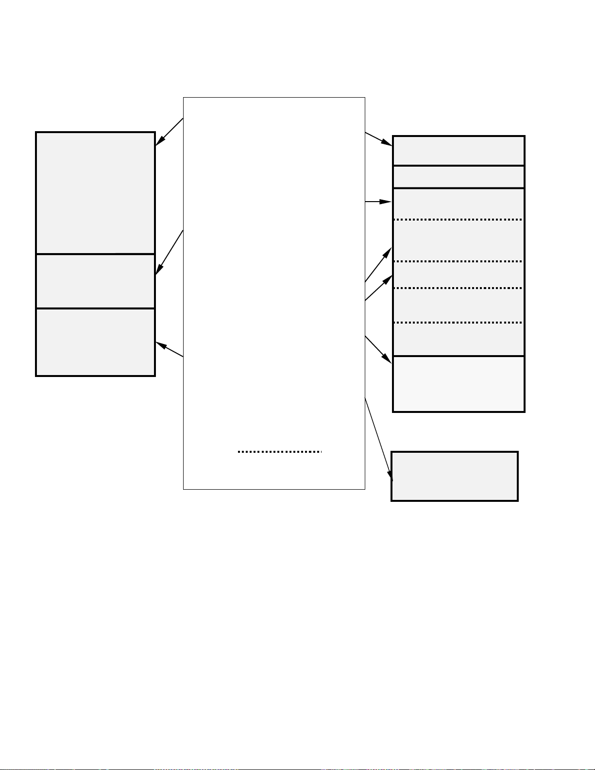
Figure 1.5-1 lists the basic memory functions
and the am
ount of
a s
memory allotted to them.
AD-1-1
Page 18
TD ADDENDUM SECTION 1. FUNCTIONAL MODES
Flash Memory
(EEPROM)
Operating System
(96 Kbytes-CR10X)
(128 Kbytes-CR23X)
Active Program
(16 Kbytes)
Input and Final
Storage Lables
(16 Kbytes)
How it works:
The Operating System is loaded into
Flash Memory at the factory. System
Memory is used while the CR10X is
running for calculations, buffering data
and general operating tasks.
Any time a user loads a program into
the datalogger, the program is
compiled in SRAM and stored in the
Active Program areas. If the
datalogger is powered off and then on,
the Active Program is loaded from
Flash and run.
The Active Program is run in SRAM to
maximize speed. The program
accesses Input Storage and
Intermediate Storage and stores data
into Final Storage for later retrieval by
the user.
Table Data Operating Systems Save
Input Storage and Final Storage
Lables.
Flash Memory, increases Final Storage
by 524,288 data values per Mbyte.
(Memory Areas separated by dashed
lines:
can be re-sized.)
SRAM
Total 128 Kbytes
32K SRAM
Main Memory
System Memory
Active Program
(automatically allocated)
Input Storage
default: 28 locations
(Size Set with *A)
Intermediate Storage
(automatically allocated)
PakBus Routing Table
(Size Set with *D 15)
PakBus Settings
(Size Set with *A)
96K SRAM
Final Storage Data
Tables
Flash EEPROM
Optional in CR10X
Final Storage
(Additional 524,288
locations per Mbyte)
FIGURE 1.5-1. Datalogger Memory
1.5.2 ∗A MO
The ∗A Mode is us
Storage, Intermediate Storage, Final Storage,
Program Memory; PakBus and user Settings
memory 2) check the number of bytes remaining in
Flash Program memory; Main Memory, and Label
Memory 3) change the memory allotted to Input
Locations and Settings; and 5) to completely reset
the datalogger.
When ∗A is
is the number of memory locations allocated to
AD-1-2
DE
ed to 1) check the size of Input
ed, the first number displayed
enter
Input Storage. The "A" key is used to advance
through the next 6 windows. Table 1.5-2
describes what the values in the ∗A Mode
represent.
The sizes of Input Storage and Settings Memory
m
ay
be altered by keying in the desired value and
entering it by keying "A".
Page 19

Keyboard Display
Entry ID: Data
A
∗
A
A
A
A
A
A
A
01: XXXX Input Storage Locations (minimum of 28, maximum of 6655,
02: XXXX Intermediate Storage Locations (maximum limited by available
03: XXXXX Final Storage Locations (minimum of 0, maximum limited by
04: XXXXX Bytes allocated for user program. The CR10X-TD will assign the
05: Bytes free in Flash Memory for active program. The user
06: PakBus and user Settings memory
07: Main Memory Free
06: Label Bytes Free
TD ADDENDUM SECTION 1. FUNCTIONAL MODES
TABLE 1.5-2. Description of ∗A Mode Data
Description of Data
but the usable maximum is less than this because intermediate
and program storage require some of this memory). This value
can be changed by keying in the desired number.
memory and constraints on Input and Final Storage). The
CR10X-TD will assign the exact number needed for the active
program. The CR10X-TD erases all data whenever the program
is changed and compiled.
available memory). Changing this number automatically
reallocates Final Storage Area 1.
exact number needed. The CR10X-TD erases all data whenever
the program is changed and compiled. Key in 98765 to
completely reset datalogger.
cannot change this window. It is a function of window 5 and the
program.
The maximum size of of Final Storage is
determined by the memory installed (Table 1.5-
1). The size of Final Storage and the rate at
which data are stored determines how long it
will take for Final Storage to fill, at which point
new data will write over old.
Twenty-eight is the minimum number of Input
allowed. Intermediate Storage and
ations
loc
Final Storage are erased when the number of
Input locations is changed. This feature may be
used to clear memory without altering
programming. The number of locations does
not actually need to be changed; the same
value can be keyed in and entered.
Intermediate Storage and Program Memory are
atic
autom
ally allocated. All data are erased any
time the program is changed and compiled. If
there is not enough memory available in the
32K Main Memory for the Intermediate Storage
required by the current program, the "E:04"
ERROR CODE will be displayed in the ∗0, ∗6,
and ∗B Modes.
After repartitioning memory, the program must be
ompiled. Compiling erases Intermediate
ec
r
Storage. Compiling with ∗0 erases Input Storage;
compiling with ∗6 leaves Input Storage unaltered
(If its size was unchanged).
ENTERING 98765 in the program memory
i
ndow 6 COMPLETELY RESETS THE CR10X.
w
All memory is erased including the program and
memory is checked. Memory allocation returns
to the default. The reset operation requires
approximately 1 minute for a CR10X, 5 minutes
for a CR10X-1M, and 10 minutes for a CR10X2M. Please be patient while the reset takes
place; if the CR10X is turned off in the middle of
a reset, it will perform the reset the next time it is
powered up.
1.6 MEMORY TESTING AND SYSTEM
STATUS - ∗B
No changes from standard operating system,
see datalogger manual.
1.7 ∗C MODE -- SECURITY
No changes from standard operating system,
see datalogger manual.
1.8 ∗D MODE – TRANSFER
PROGRAMS, GENERAL SETTINGS
The ∗D Mode is used to transfer datalogger
programs between a datalogger and a
computer, to erase a program, to set the degree
AD-1-3
Page 20

TD ADDENDUM SECTION 1. FUNCTIONAL MODES
to which memory is cleared on powerup, to set
the PakBus ID, and to set communication to full
or half duplex.
CSI datalogger support software makes use of the
∗D Mode to upload and download pr
computer. Appendix C gives some additional
information on Commands 1 and 2 that are used
for these operations.
When "∗D
"13:00". A c
by keying the command number and "A".
Command Description
If the CR10X program has not been compiled
when the command to save a program is entered,
it will be compiled before the program is saved.
When a program is loaded, it is immediately
compiled and run. When a command is complete,
"13:0000" is displayed; ∗D must be entered again
before another command can be given.
TABLE 1.8-2. Progr am Load Error Codes
E 94 Program Storage Area full
E 95 Program does not exist in flash
E 96 Storage Module not connected or
E 97 Data not encountered within 30 sec.
E 98 Uncorrectable errors detected
E 99 Wrong type of file or Editor Error
1.8.1 ERASING CURRENT PROGRAM
The 7 command may be used to delete the
cur
rent program as show in Table 1.8-3.
" is keyed in, the CR10X will display
ommand (Table 1.8-1) is entered
TABLE 1.8-1. ∗D Mode
1 Send (Print) ASCII Program
2 Load ASCII Program, ∗0 Compile
2-- Load ASCII Program, ∗6 Compile
3 # Rings Before Answering Phone
7 Erase Current Program
10 Set Powerup Options
12 Set Initial Baud
15 PakBus Address/Routing Table
16 Memory for General Purpose File
17 PakBus Routing Table
18 PakBus Beacon Interval
19 PakBus Neighbor List
r
ong address
w
ograms from a
Commands
TABLE 1.8-3 Deleting Current Datalogger
Program
Key entry Display
∗D 13:00
7A
You may now enter:
0A Erase active program (i.e., load a
1.8.2 PROGRAM TRANSFER WITH STORAGE MODULE
Not supported in Table Data Operating
stems.
Sy
1.8.3 FULL/HALF DUPLE X
Not supported in Table Data Operating
y
stems.
S
1.8.4 SET DATALOGGER ID
Command 8 not supported in Table Data
per
ating Systems.
O
1.8.5 SETTING POWERUP OPTIONS
Setting options for the Program on Powerup
s
the user to specify what information to
allow
retain from when the datalogger was last on.
This allows Flag/Port status, the User Timer,
and the Input/Intermediate Storage to be
cleared or not cleared.
Table 1.8-8. Setting Powerup Options
Key entry Display
∗D 13:00
10A
Where X is the powerup option currently
ted. You may now change the option:
selec
0A Clears input locations, ports, flags, user
timer
1A Clears intermediate storage only (leaves
Input Stor
as is).
2A Doesn’t clear anything.
07:00
blank pr
and Final Storage are reset).
10:0X
, and intermediate storage locations.
age, F
ogram; memory allocation
lags/Ports, and User Timer
AD-1-4
Page 21

TD ADDENDUM SECTION 1. FUNCTIONAL MODES
1.8.6 SET INITIAL BAUD
Table 1.8-10 shows the option codes available
for
setting the initial baud rate. Setting the initial
baud rate forces the CR10X to try the selected
baud rate first when connecting with a device.
TABLE 1.8-9. Set Initial Baud Rate / Set
RS232 Power
Key
Entry Display Comments
*D 13:00 Enter Command
12A 12:00 Connect Baud Rate
Enter Baud Rate Code X
(Table 1.8-11).
TABLE 1.8-10. Baud Rate Codes
X = 0 300 Baud
X = 1 1200 Baud
X = 2 9600 Baud
X = 3 76.8 K Baud
TABLE 1.8-11. PakBus Address and
Routing Table
Key
Entry Display Comments
*D 13:00 Enter Command
15A 15:xxxx PakBus Address , Enter zero if
the datalogger is
as a PakBus device (1..4094 is
legal, the default is 1)
A 01:xxxx If the datal
a router, enter the maximum
number of nodes (PakBus
Addresses) to a llocate space
for in the pakbus network. 0 =
leafnode, <>0 = router
A 02:xxxx Enter the maximum number of
neighbor
network to allocate space for.
This parameter is used only if
datalogger is used as a router
(01: is non-zero).
s
not to be used
ogger i
in the pakbus
s to be used a
1.8.7 SET PROGRAM COMPILE OPTION
Command 13 is not supported in Table Data
operating s
1.8.8 SET PAKBUS ADDRESS
*D 15 allows the user to set the PakBus
Addr
maximum size for its routing table.
ystems.
es
s of the datalogger and to set the
A 03:xxxx Enter maximum number of
outer
s in the pakbus network
r
to allocate space for. This
parameter is used only if
datalogger is used as a router
(01: is non-zero).
A 04:xxxx Enter the PakBus address for a
ault r
def
default router). The default
router is used for a message if
the destination PakBus
address is not in the routing
table. A router discovering new
routes will not explore beyond
its own default router.
The memory for a routing table comes out of
the pool for program, input locations, and
intermediate storage.
The total number of bytes used for the routing
table =
Nodes x 12
+ Neighbors x 8
+ Routers x 6
+ (Routers x (Nodes – Routers) + (Routers
(
Routers – 1))/2) x 4
x
outer (1..4094, 0 for no
AD-1-5
Page 22

TD ADDENDUM SECTION 1. FUNCTIONAL MODES
The *D15 entries are sent when the program is
retrieved. They can also be set like other *D
settings via the DLD file.
1.8.9 ALLOCATE MEMORY FOR GENERAL
PURPOSE F
*D16:xx ;allocate xx 64K byte chunks of
1.8.10 VIEW ROUTING TABLE
*D17 allows viewing the current routing table
rmation. This is view only.
o
inf
TABLE 1.8-12. Values in Routing Table
Key
Entry Display
*D 13:00 Enter Command
17A Enter the view routing table
(Repeats for next destination node.)
ILES
ory for general purpose files.
mem
The area comes out of final storage
space. Files are stored in a circular
buffer (ring memory) in this space.
Comments
com
mand
01:xxxx ;pakbus address of desti
node
02:xxxx ;via neighbor w
address
03:xxxx ;a worst case response tim
metric (seconds)
ith xxxx pakbus
nation
e
1.8.11 SET PAKBUS ROUTER BEACON INTERVAL
TABLE 1.8-13. Set Beacon interval
Key
Entry Display
*D 13:00 Enter Command
18A Enter the beacon interval
A
A 02:xxxx Enter the Interval (seconds) for
A 03:xxxx Enter the Interval (seconds) for
A
1.8.12 PAKBUS NEIGHBOR FILTER
In some networks, sending beacons can be
disr
disables the beacon. A PakBus datalogger with
nonzero *D19 settings will not send beacons
and will only respond to beacons from nodes
with addresses in the neighbor list.
Instead of sending beacons, the datalogger will
end “
s
determine if it can communicate with them.
Neighbors (or potential neighbors) should be
nodes that communicate directly with the
datalogger without going through a router.
01:xxxx Enter the Interval (seconds) for
04:xxxx Enter the Interval (seconds) for
uptive. Entering values in the *D19 mode
hello” messages to neighbors in the list to
Comments
settings
SDC7
SDC8
Pin Enabled, 9600 baud
CS I/O
RS232, 9600 baud (
only
)
CR23X
AD-1-6
Note that this list is not automatically cleared by
om
piling a new program. (It may be changed
c
if the new program contains *D19 entries.) It
can be edited by changing entries. Once 0 is
entered for a neighbor address, all entries
beyond the 0 entry are cleared.
Page 23

TD ADDENDUM SECTION 1. FUNCTIONAL MODES
TABLE 1.8-14. Set PakBus Neighbors
Key
Entry Display
*D 13:00 Enter Command
19A 19:00 Port (17- SDC7, 18 – SDC8, 02
A 19:0000 Interval in seconds of the
A 01:xxxx PakBus Address of
A 01:xx Swath of neighbors with
A 02:xxxx PakBus Address of
A 02:xx Swath of neighbors with
Comments
– CSI/O, 02—CR23X
port, 9600 baud
pec
ted rate of
ex
communication. A neighbor is
aged after 2.5 times this
interval and the Hello attempt
will be reinitiated.
sequential addr
with above address.
sequential addr
with above address.
RS232
ghbor
nei
esses starting
nei
ghbors
esses starting
1.9 *9 DATA TABLES SIZES.
The *9 Mode is used to view the sizes of the
Data Storage Tables (section 2.1) created by
the datalogger program (*1, *2, or *3). The *9
Mode will also display how long until any
automatically allocated Data Storage Tables fill.
All Data Storage Tables are in a ring
configuration such that the oldest records are
overwritten by new records once the table is full.
The sizes are given as the number of records.
A record can be thought of as a row of data
where each field (i.e., column) is a data value
associated with an Output Processing
Instruction. The order and number of fields in a
Data Table are determined by the Output
Processing Instructions following the Data Table
Instruction. The tables are numbered in the
order the Data Table Instruction appear in the
Program Tables, *1 first, *2 second, and *3 last.
... etc.
A nn:0000 Terminates the list.
TABLE 1.9-1. Description of * 9 Data
Keyboard Display
Entry ID: Data
*9 09:xx Number of tables/ Enter table number to jump to that table or 0
0A 00:x.xxxx Days before any automatically allocated table fills.
A 0
A 02:xxxxx Number of records in table 02
A nn:xxxxx. Number of records in table nn
1:xxxxx. Number of records in table 01
Description
to see next parameter.
AD-1-7
Page 24

TD ADDENDUM SECTION 1. FUNCTIONAL MODES
This is a blank page.
AD-1-8
Page 25

THIS SECTION ENTIRELY REPLACES THE DATALOGGER MANUAL SECTION 2.
SECTION 2. INTERNAL DATA STORAGE
2.1 FINAL STORAGE AND DATA TABLES
Final Storage is that portion of memory where
final processed data are stored. It is from Final
Storage that data is transferred to your
computer. With the TD datalogger, Final
Storage is organized into Data Storage Tables.
These data tables should not be confused with
the program tables *1, *2, and *3 that contain
the datalogger program.
Within each data table, data is organized in
ec
ords and fields. Each row in a table
r
represents a record and each column
represents a field. To understand the concept
of tables it may be helpful to consider an
example. A CR10X is to be used to monitor 3
thermocouples (TC). Each hour a temperature
for each of the three TC is to be stored. The
table has 4 fields: "DATE_TIME TEMP1 TEMP2
TEMP3." Each hour a new "record" would be
added. The "hourly" table would then be
organized as follows:
DATE_TIME TEMP1 TEMP2 TEMP3
01/27/91 10:00:00 23.5 24.6 28.2
01/27/91 11:00:00 24.2 22.4 23.4
Only the hourly data is stored in the hourly table,
h output inter
Eac
tables can also be "event driven" rather than
interval driven, that is a new record is stored
when a specified event occurs rather than
based on time. Each table is completely
independent of any other tables and all records
in a given table have the same number of fields.
Each table is allocated (manually by the user or
atic
autom
records. Different tables have different
numbers of records. Each data table is in a ring
memory configuration such that when the
allocated number of records has been stored,
each subsequent new record will overwrite the
oldest stored record. The *9 Mode may be
used to view the size of the Data Storage
Tables. (Section 1.9)
The TD datalogger supports naming of tables and
elds, so any data value can be referenced by the
i
f
table and field names. For example, the
ally by the datalogger) a number of
val has its own table. Data
temperature data for the first thermocouple is
referenced as "HOURLY.TEMP1." As Data Tables
are allocated in the datalogger program, some
Final Storage Memory is reallocated for the
storage of these labels and other data table
overhead.
NOTE: All Data Storage Tables are
reallocated and erased whenever the
datalogger program is recompiled (*0, *6,
*B), when Input Storage Memory is
reallocated (*A), or when a new datalogger
program is transferred from the computer to
the datalogger. ALWAYS RETRIEVE
UNCOLLECTED DATA BEFORE MAKING
ANY CHANGES.
A time stamp and record number are
automatically included with the each record in
each table. These are used as part of the data
collection protocol.
2.1.1 TIME AND TIMESTAMPS
Each record in a table has a time stamp
s
ociated with it. With Instruction 84 set for
as
interval output (a interval in seconds is specified
as the second parameter), time is not actually
stored with each record. Using the timestamp
of the last record stored and the table interval,
the datalogger can calculate the timestamp for
any previous record. When retrieved, each
record in the data file will have a timestamp.
This saves 6 bytes per record by not storing
time with each record. A consequence of not
storing time is that if output does not occur at a
scheduled time, the datalogger must keep track
of the discontinuity in the timestamps so it can
correctly calculate timestamps for records older
than the missing record. The datalogger will
keep track of the 10 most recent discontinuities
in each table. If more than ten discontinuities
occur, records with timestamps older than the
oldest discontinuity cannot be reliably
timestamped when collected. For this reason
interval tables should not be used if outputs will
be routinely missed. Outputs can be missed
(discontinuities can occur) when:
• The datalogger clock is changed such that
is passes an output interval.
AD-2-1
Page 26

TD ADDENDUM—SECTION 2. INTERNAL DATA STORAGE
The output interval is not an even multiple
•
of the scan rate (table execution interval).
• Table execution is such that Instruction 84
is not executed each scan.
• Table overruns occur.
• Watchdog errors (E08) occur.
2.1.2 RECORD NUMBERS
In addition to a timestamp, each record has
ord number. The record numbers are
rec
unique within a data table. Record numbers are
4 byte unsigned numbers ranging from 0 to
4,294,967,296. When the datalogger program
is compiled the next record number for each
table is set to zero.
2.1.3 TABLES AND FIELDS.
There are four "built in" tables. These tables
e pr
esent when the datalogger is powered on.
ar
These tables are named INLOCS, TIMESET,
ERRORLOG, and STATUS. The fields within
these tables are also already defined with the
exception of the INLOCS. The field names for
each of the fields is given below. TmStamp is
the label for the timestamp and RecNbr is the
label for the record number.
TimeSet
TmStamp, RecNbr, OldTime
ErrorLog
TmStamp, RecNbr, Code
Status
TmStamp, RecNbr, Battery, WatchDog,
v
erRuns, InLocs, PrgmFree, Storage, Tables,
O
DaysFull, Holes, PrgmSig, PromSig, PromID,
ObjSrlNo
Where the labels are defined as follows:
ates
Battery − Indic
voltage.
the datalogger battery
Storage − Number
available for Data Storage Tables. Section
1.5.2
Tables − Num
DaysFull − Size (
Tables using automatic record allocation. See
Instruction 84.
Holes − Num
all Data Storage Tables. Section 2.1.1
PrgmSig − Signature of
program. Same as *B mode first window.
Section 1.6.
PromSig − Signatur
as *B mode second window. Section 1.6.
Prom ID − Item num
mode seventh window. Section 1.6.
ObjSrlNo − Obj
PROM. Same as *B mode eighth window.
Section 1.6.
Like the InLocs table, a new Status record is
ys available when the datalogger is checked
alwa
for data. For this reason the Status table is usually
collected for display rather than archive.
InLocs
TmStamp, RecNbr, Flags, Ports, Loc1, Loc2,
4, Loc5, Loc6, Loc7, Loc8, Loc9
3, Loc
Loc
Like the Status table, a new InLocs record is
ys available when the datalogger is checked
alwa
for data. For this reason these tables are usually
collected for display rather than archive.
By default only nine Input Location are labeled.
he def
T
with user created labels. These labels are
created with EDLOG technique for Input
Location labels. Press CTRL-L when editing a
LOC field.
ault InLocs field labels can be replaced
of Final Storage Locations
ber
of user created Data Tables.
in days) of the Data Storage
ber
of missed records or holes in
program memory
e of
datalogger PROM. Same
ber of PROM. Same as *B
ect code serial number of
WatchDog − The num
(E08). (Maximum 99). Section 3.10
OverRuns − Progr
occurred (Maximum 99). Section 1.1.1.
InLocs − Number
been allocated. Section 1.5.2
PrgmFree − Amount (
remaining. Section 1.5.2
AD-2-2
ber of Watchdog Errors
am table overruns that have
of Input Location that have
bytes) of program memory
When additional data tables are created with
t
ruction 84, these tables and the fields they
Ins
contain can also be named by the user. The
datalogger will supply a default name for tables
and fields if they are not named. The default
names are T01, T02, for the tables and F01,
F02, etc. for the fields, numbered in the order
they appear. Edlog allows the programmer to
name the tables and fields.
Page 27

TD ADDENDUM—SECTION 2. INTERNAL DATA STORAGE
The Timestamp and record number labels are
added automatically.
2.2 DATA OUTPUT FORMAT AND
RANGE LIMITS
Data is stored internally in Campbell Scientific's
Binary Final Storage Format (Appendix C.2).
Data may be sent to Final Storage in either
LOW RESOLUTION or HIGH RESOLUTION
format.
2.2.1 RESOLUTION AND RANGE LIMITS
Low resolution data is a 2 byte format with 4
gnificant digits and a maximum magnitude of
i
s
+7999. High resolution data is a 4 byte format
(see Section 2.2.2).
TABLE 2.2-1. Resolution Range Limits of
CR10 Data
Minimum Maximum
Resolution Zero
Low 0.000 + 0.001 +7999.
High 0.0000 1x10
The resolution of the low resolution format is
reduced to 3 significant digits when the first (left
most) digit is 8 or greater. Thus, it may be
necessary to use high resolution output or an
offset to maintain the desired resolution of a
measurement. For example, if water level is to
be measured and output to the nearest 0.01 ft.,
the level must be less than 80 ft. for low
resolution output to display the 0.01 ft.
increment. If the water level was expected to
range from 50 to 90 feet the data could either
be output in high resolution or could be offset by
20 ft. (transforming the range to 30 to 60 ft.).
2.2.2 HIGH RESOLUTION FINAL STORAGE
T
A, INPUT, AND INTERMEDIATE
DA
STORAGE DATA FORMAT
While low resolution output data have the limits
described above, computations are done in
floating point arithmetic. In high resolution Final
Storage Input and Intermediate Storage, the
numbers are stored and processed in a binary
format with a 23 bit binary mantissa and a 6 bit
binary exponent. The largest and smallest
numbers that can be stored and processed are
18
9 x 10
and 1 x 10
the number determines the resolution of the
Magnitude Magnitude
-19
19
-
, respectively. The size of
+9x10
+18
arithmetic. A rough approximation of the
resolution is that it is better than 1 in the
seventh digit. For example, the resolution of
97,386,924 is better than 10. The resolution of
0.0086731924 is better than 0.000000001.
A precise calculation of the resolution of a
number may be determined by representing the
number as a mantissa between .5 and 1
multiplied by 2 raised to some integer power.
The resolution is the product of that power of 2
24
-
and 2
.9336 * 2
. For example, representing 478 as
9
, the resolution is 29 * 2
24
= 2
15
-
-
0.0000305. A description of Campbell
Scientific's floating point format may be found in
Appendix C.
2.3 DISPLAYING STORED DATA ON KEYBOARD/DISPLAY *7 MODE.
The keyboard display (or the computer in
Keyboard/Display mode) can be used to
examine Data Storage Tables in Final Storage
table data.
Key *7. The display will show: 07:nn where nn
the num
is
Enter a table number (followed by the “A” key)
to view that table. Tables are numbered in the
order of the appearance of the Data Storage
Table Instruction (84) in the datalogger
program. Tables in the *1 program area are
numbered first, followed by *2 and those in the
*3 subroutines numbered last.
The display will then show the first field of the
new
not change, the select table has not had any
data stored in it yet.
When a table is visualized the newest data
ec
ord is at the bottom and the oldest is at the
r
top. When the table is full and a new record is
stored, the records shift up pushing the oldest
record off the top and storing the new record at
the bottom.
The display (or value displayed on the
om
c
can be moved up and down or right and left
through the data. The display shows the field
number to the left of the colon and the data
value to the right. The keys used to move the
display/cursor are summarized in the following
table:
ber of Data Storage Tables defined.
es
t record in the table. If the display does
puter) can be thought of as a cursor, which
=
AD-2-3
Page 28

TD ADDENDUM—SECTION 2. INTERNAL DATA STORAGE
TABLE 2.3-1. *7 Mode Command Summary
KEY ACTION
A "Advances" along a record, when the
end of the record is reached the
'cursor' advances to the first field in
the next record.
B "Backs" up along a record, wraps to
element in the previous
the las
record
C "Climbs" up the table, toward the
oldes
D "Drops" down the table, toward the
newes
# Enter Time Mode to display timestamp.
Enter new tim
Each record of data in a table has a time
associated with it. Event data stores the time
as part of the data, interval tables calculate the
time based on the interval and a reference time.
The time associated with each record consist of
a year, month/day, hour/minute, and seconds
value. Julian dates are not used. When
viewing data in the *7 mode, event data records
have time as part of the record. The field
number on the keyboard/display does not
change while viewing the four time values since
time is considered a single field. Interval data
does not contain time and it is not displayed as
part of the record. To see the time values for a
given record, press the # key while viewing any
of the fields within the record.
t
t data, s
t data, stops on newest record.
tops on oldest record.
e values to jump to record.
records long is maintained inside Intermediate
Storage to keep track of "holes" in the recorded
data, due to watch dog errors or clock changes,
so that the time of each record can be implicitly
maintained.
This "hole" table rings around, and any recorded
data that c
"hole" table cannot be displayed.
To view the “hole” table for a given table, Key
*7. The dis
the number of Data Storage Tables defined.
Enter the number of table where you want to
view the “holes." Then press the C key
followed by the A key. The Hole table fields are
as follows:
01:time of hole;
02:number of holes.
annot be tim
play will show: 07:nn, where nn is
e stamped using this
The A and B key are used move through the
our
time values for the record. The C and D
f
keys can be used to move to newer or older
records and view the same time value of the
new record. Pressing the # key again while
viewing time or using the A or B keys to
advance or back beyond the time values will
return the display to the same field as was
displayed when the time mode was entered.
The time field is displayed as: day.month, year,
:m
in, seconds
hr
While viewing time, entering new time values
will allow
time values closest to those entered. The jump
takes place when the time mode is left.
Interval tables do not store time as part of the
ec
r
AD-2-4
the display to jump to the record with
ord, but calculate the time. A table 10
Page 29

SECTION 3. INSTRUCTION SET BASICS
Section 3.7.1 does not apply to the TD operating system which does not use Output Flag 0.
Table 3.8-1 Valid Flag Commands are 11 – 19 to set high and 21- 29 to set low. Because the TD
operating system does not use Fl
ag 0, Commands 10 and 20 are not valid with the TD operating system.
The following table replaces Table 3.10-1 for the TD operati
TABLE 3.10-1. Error Codes
Code Type Description
03 Editor Program table full
04 Compile Intermediate Storage full
05 Compile Storage Area #2 not
alloca
ted
08 Run Time CR10X reset by
hdog timer
watc
09 Run Time Insufficient Input Storage
10 Run Time Low Battery Voltage
11 Editor Attempt to allocate more
Input or Inter
Storage than is available
20 Compile SUBROUTINE encountered
or
e END of previous
bef
subroutine
21 Compile END without IF, LOOP or
SUBRO
22 Compile Missing END
23 Compile Nonexistent
SUBROU
24 Compile ELSE in SUBROUTINE
thout IF
wi
25 Compile ELSE without IF
26 Compile EXIT LOOP without
LOOP
27
28 Compile At compile time, no
Compile IF CASE without BEGIN
CASE
output s
or unable to automatically
allocate at least one
record per P84
mediate
U
TINE
TINE
pec
ified after P84
29 Compile Output table requests
30 Compile IF and/or LOOP nested
31 Run Time SUBROUTINES nested
32 Compile Instruction 3 and interrupt
33 Compile Cannot use Control Port
40 Editor Instruction does not exist
41 Editor Incorrect execution
43 Compile Time in Instruction 84 or
44 Compile Loop (P87) cannot
60 Compile Insufficient Input Storage
61 Compile Burst Measurement Scan
62 Compile N<2 in FFT
68 Compile Instruction 118 without
80 Compile Illegal Interval in P193
81 Compile Illegal Node ID in P193
82 Compile Illegal Reps in P193
92 Compile Instruction 92, intervals in
ng system.
r
e memory than
mo
available
too deep
too deep
ubr
outine use same port
s
ounter or interrupt
6 as c
subroutine with
Instruction 15 or SDM or
SDI-12 input/output
v
al
inter
92 is not a m
execution interval (note:
time is in seconds)
ontain Data T
c
Rate too shor
enough Inst
onds: Time into Interval
sec
> 59 or Interval > 60
ultiple of
able (P84)
t
ructions 68 or 63
AD-3-1
Page 30

TD ADDENDUM—SECTION 3. INSTRUCTION SET BASICS
94 Program Program Storage Area
Transfer full
95 Program Program does not exist in
ansfer Flash memory
Tr
96 Program Addressed
ansfer device not connected
Tr
97 Program Data not received within
ansfer 30 seconds
Tr
98 Program Uncorrectable errors
ansfer detected
Tr
99 Program Wrong file type or editor
ansfer error
Tr
AD-3-2
Page 31

THIS SECTION ENTIRELY REPLACES THE CR10X MANUAL SECTION 8.
SECTION 8. PROCESSING AND PROGRAM CONTROL EXAMPLES
This section contains examples for the CR10X. The appropriate voltage range codes would have to be
selected for the CR23X (see CR23X Manual Section 8 for the measurement instructions). The CR510TD may not support all the examples.
The following examples are intended to illustrate the use of Processing and Program Control
t
ructions, flags, and the capability to direct the results of Output Processing Instructions to Input
Ins
Storage.
The specific examples may not be as important as some of the techniques employed, for example:
Directing Output Processing to Input Storage is used in the Running Average and Rainfall Intensity
amples
ex
Flag tests are used in the Running Average, Interrupt Subroutine, and Converting Wind Direction
.1, 8.5, and 8.7).
(8
Control ports and the Loop are illustrated in the AM32 example (8.3).
As in Section 7 these examples are not complete programs to be taken verbatim. They need to be
altered to fit s
(8.1 and 8.2).
pecific needs.
8.1 COMPUTATION OF RUNNING AVERAGE
It is sometimes necessary to compute a running
average (i.e., the average covers a fixed
number of samples and is continuously updated
as new samples are taken). Because the
output interval is shorter than the averaging
period, Instruction 71 cannot be used; the
algorithm for computing this average must be
programmed by the user. The following
example demonstrates a program for
computing a running average.
In this example, each time a new measurement
ade (in this case a thermocouple
m
is
temperature) an average is computed for the 10
most recent samples. This is done by saving all
10 temperatures in contiguous input locations
and using the Spatial Average Instruction (51)
to compute the average. The temperatures are
stored in locations 11 through 20. Each time
the table is executed, the new measurement is
stored in location 20 and the average is stored
in location 2. The Block Move Instruction (54) is
then used to move the temperatures from
locations 12 through 20 down by 1 location; the
oldest measurement (in location 11) is lost
when the temperature from location 12 is
written over it.
Input Location Labels:
1:Panl Temp 15:Temp_i5
2:smpl10av 16:Temp_i4
11:Temp_i9 17:Temp_i3
12:Temp_i8 18:Temp_i2
13:Temp_i7 19:Temp_i1
14:Temp_i6 20:Temp_i
Where i is current reading, i1 is previous
eading, etc
r
* 1 Table 1 Programs
01: 10 Sec. Execution Interval
01: P17 Module Temperature
01: 1 Loc [:Panl_Temp]
02: P14 Thermocouple Temp (DIFF)
01: 1 Rep
02: 1 2.5 mV slow Range
03: 1 IN Chan
04: 1 Type T (Copper-Constantan)
05: 1 Ref Temp Loc Panl_Temp
06: 20 Loc [:Tempi ]
07: 1 Mult
08: 0 Offset
03: P51 Spatial Average
01: 10 Swath
02: 11 First Loc Temp_i9
03: 2 Avg Loc [:smpl10avg]
04: P54 Block Move
01: 9 No. of Values
02: 12 First Source Loc Temp_i8
03: 1 Source Step
04: 11 First Destination Loc
05: 1 Destination Step
.
p_i9 ]
em
[:T
AD-8-1
Page 32

TD ADDENDUM—SECTION 8. PROCESSING AND PROGRAM CONTROL EXAMPLES
05: P84 Data Table
01: 0 Seconds into interval
02: 0 Every time
03: 0 Records (0=auto; -=redirect)
06: P70 Sample
01: 1 Reps
02: 2 Loc smpl10avg
07: P End Table 1
In the above example, all samples for the
age ar
aver
necessary when an average must be output
with each new sample. In most cases,
averages are desired less frequently than
sampling. For example, it may be necessary to
sample some parameter every 5 seconds and
output every hour an average of the previous
three hours' readings. If all samples were
saved, this would require 2160 input locations.
The same value can be obtained by computing
an hourly average and averaging the hourly
averages for the past three hours. To do this
requires that hourly averages be stored in input
locations.
Instruction 84 is used to send the 1 hour
aver
3 hour average to Final Storage.
Input Location Labels:
* 1 Table 1 Programs
01: 5 Sec. Execution Interval
01: P2 Volt (DIFF)
01: 1 Rep
02: 25 2500 mV 60 Hz rejection Range
03: 3 IN Chan
04: 5 Loc [:XX_mg_M3 ]
05: 10 Mult
06: 0 Offset
02: P84 Data Table
01: 0 Seconds into interval
02: 3600 Seconds interval
03: -3 Records (0=auto; -=redirect)
03: P71 Average
01: 1 Rep
02: 5 Loc XX_mg_M3
04: P51 Spatial Average
01: 3 Swath
e stored in input locations. This is
age to Input Stor
1:AVG_i2
2:AVG_i1
3:AVG_i
4: AVG_3_HR
5:XX_mg_M3
age and again to send the
02: 1 First Loc AVG_i2
03: 4 Avg Loc [:Avg_3_HR ]
05: P84 Data Table
01: 0 Seconds into interval
02: 3600 Seconds interval
03: 0 Records (0=auto; -=redirect)
06: P70 Sample
01: 1 Reps
02: 4 Loc Avg_3_HR
07: P92 If time is
01: 0 seconds into a
02: 3600 second interval
03: 30 Then Do
08: P54 Block Move
01: 2 No. of Values
02: 2 First Source Loc AVG_i1
03: 1 Source Step
04: 1 First Destination Loc
_i2 ]
[:AVG
05:
09: P95 End
10: P End Table 1
1 Destination Step
8.2 RAINFALL INTENSITY
In this example, the total rain for the last 15
minutes is output only if any rain has occurred.
The program makes use of the capability to
direct the output of Output Processing
Instructions to Input Storage.
Every 15 minutes, the total rain is sent to Input
age. If
Stor
redirected to Final Storage Area 1, the time is
output and the total is sampled.
Input Location Labels:
1:Rain_mm
2: TOT_15mm
* 1 Table 1 Programs
01: 60 Sec. Execution Interval
01: P3 Pulse
01: 1 Rep
02: 1 Pulse Input Chan
03: 2 Switch closure
04: 1 Loc [:Rain_mm ]
05: .254 Mult
06: 0 Offset
02: P86 Do
01: 21 Set low Flag 1
the total is not equal to 0, output is
AD-8-2
Page 33

TD ADDENDUM—SECTION 8. PROCESSING AND PROGRAM CONTROL EXAMPLES
03: P92 If time is
01: 0 seconds into a
02: 900 second interval
03: 11 Set high Flag 1
04: P84 Data Table
01: 0 Seconds into interval
02: -1 When flag 1 is high
03: -2 Records (0=auto; -=redirect)
05: P72 Totalize
01: 1 Rep
02: 1 Loc Rain_mm
06: P89 If X<=>F
01: 2 X Loc TOT_15min
02: 1 =
03: 0 F
04: 21 Set low Flag 1
07: P84 Data Table
01: 0 Seconds into interval
02: -1 When flag 1 is high
03: 0 Records (0=auto; -=redirect)
08: P70 Sample
01: 1 Reps
02: 2 Loc TOT_15min
09: P End Table 1
8.3 USING CONTROL PORTS AND LOOP TO RUN AM416 MULTIPLEXER
This example uses an AM416 to measure 16
copper-constantan thermocouples and 16
Model 223 soil moisture blocks. The sensors
are read every ten minutes and the average
value output once an hour. The multiplexer is
housed in an AM-ENCT enclosure to minimize
thermocouple errors created by thermal
gradients. A 107 Temperature Probe is
centrally located on the multiplexer board and
used as a thermocouple temp. reference.
The AM416 switches the 223 moisture block
the c
out of
This eliminates the need for the blocking
capacitors used in the model 227 Soil Moisture
Block. The 223 blocks are about one fifth the
cost of the 227 blocks.
Control ports are used to reset the AM416 and
ock it through its channels. The program
l
c
sequence is:
Measure the 107 probe located at the
AM416 f
CR10 sets the port high which resets the AM416.
A loop is entered; within each pass:
CR10 sets the port controlling AM416 reset low.
Soil moisture measurements are converted
to block
The input location in which the temperature and
il moisture measurements are stored is indexed
so
to the loop counter (Instruction 87, Section 12). An
indexed location is incremented by one with each
pass through the loop. For example, on the first
pass temperature is stored in Location 2, and soil
moisture in Location 18. On the second pass
temperature is stored in Location 3, and soil
moisture in Location 18. After 16 loop passes,
temperature and soil moisture measurements
occupy Locations 2 through 17 and 18 through 33,
respectively. Connections are shown in Figure
8.3-1.
ircuit when it is not being measured.
or
TC temperature reference.
The port clocking the AM416 is pulsed.
The connected TCs and moisture blocks
easured.
e m
ar
resistances.
AD-8-3
Page 34

TD ADDENDUM—SECTION 8. PROCESSING AND PROGRAM CONTROL EXAMPLES
FIGURE 8.3-1. AM416 Wiring Diagram For Thermocouple and Soil Moisture Block Measurements
EXAMPLE PROGRAM MULTIPLEXING
THERMOCOUPLES AND SOIL MOISTURE
BLOCK
* 1 Table 1 Programs
01: 600 Sec. Execution Interval
01: P11 Temp 107 Probe
01: 1 Rep
02: 4 IN Chan
03: 1 Excite all reps w/EXchan 1
04: 1 Loc [:REF_TEMP ]
05: 1 Mult
06: 0 Offset
02: P86 Do
01: 41 Set high Port 1
03: P87 Beginning of Loop
01: 0 Delay
02: 16 Loop Count
04: P86 Do
01: 72 Pulse Port 2
05: P14 Thermocouple Temp (DIFF)
01: 1 Rep
02: 21 2.5 mV 60 Hz rejection
03: 1 IN Chan
04: 1 Type T (Copper-Constantan)
05: 1 Ref Temp Loc REF_TEMP
06: 2-- Loc [:TC_TEMP_1]
07: 1 Mult
08: 0 Offset
CR10X
Range
06: P5 AC Half Bridge
01: 1 Rep
02: 14 250 mV fast Range
03: 3 IN Chan
04: 1 Excite all reps w/EXchan 1
05: 250 mV Excitation
06: 18-- Loc [:SOIL_M_1 ]
07: 1 Mult
08: 0 Offset
07: P95 End
08: P86 Do
01: 51 Set low Port 1
09: P59 BR Transform Rf[X/(1-X)]
01: 16 Reps
02: 18 Loc [:SOIL_M_1 ]
03: .1 Multiplier (Rf)
10: P84 Data Table
01: 0 Seconds into interval
02: 3600 Seconds interval
03: 0 Records (0=auto; -=redirect)
11: P71 Average
01: 33 Reps
02: 1 Loc REF_TEMP
12: P End Table 1
AD-8-4
Page 35

TD ADDENDUM—SECTION 8. PROCESSING AND PROGRAM CONTROL EXAMPLES
8.4 INTERRUPT SUBROUTINE USED TO COUNT SWITCH CLOSURES (RAIN GAGE)
Subroutines given the label of 97 or 98 will be
executed when control ports 7 or 8,
respectively, go high (5 V, see Instruction 85,
Section 12). In this example, Subroutine 98 and
control port 8 are substituted for a pulse
counting channel to count switch closures on a
tipping bucket rain gage.
The subroutine adds 0.254 (mm, bucket
ated for 0.01 inch tip) to an input location
alibr
c
and uses Instruction 22 to delay 0.2 seconds.
The delay is to insure that any switch bouncing
hen closing, the contacts actually bounce off
(w
each other, making and breaking the circuit
several times) has died out before the
subroutine is completed. (The pulse count
inputs do this automatically.) Without the delay,
the subroutine could be completed and called
again by a bounce, causing false counts. The
interrupt has no effect while the subroutine is
still being executed.
Input location Assignments:
10:Rain_1 (from Pulse count)
11:Rain_2 (from Pulse count)
12:Rain_3 (from subroutine 98 while
utput F
O
* 1 Table 1 Programs
01: 10 Sec. Execution Interval
01: P3 Pulse
01: 2 Reps
02: 1 Pulse Input Chan
03: 2 Switch closure
04: 10 Loc [:Rain_1 ]
05: .254 Mult
06: 0 Offset
02: P84 Data Table
01: 0 Seconds into interval
02: 3600 Seconds interval
03: 0 Records (0=auto; -=redirect)
03: P72 Totalize
01: 2 Reps
02: 10 Loc Rain_1
04: P70 Sample
01: 1 Reps
02: 12 Loc Rain_3
lag is low)
Subroutine 98 is in effect keeping a running
total in Input Stor
this total is sampled to Final Storage and
zeroed by the program in Program Table 1.
To provide comparison, this example has the 2
e inputs
puls
situation, it is more likely that the pulse counters
would be used for 2 wind speeds.) In Program
Table 1, the 2 normal pulse inputs are read and
the hourly totals output to Final Storage with
Instruction 72.
The rain gage is connected as diagrammed
. W
below
applied to port 8 which causes the subroutine to
be executed.
hen the switch closes, 5 volts is
age. O
also reading rain gages. (In a real
n the output interval,
05: P92 If time is
01: 0 seconds into a
02: 3600 second interval
03: 30 Then Do
06: P30 Z=F
01: 0 F
02: 0 Exponent of 10
03: 12 Z Loc [:Rain_3 ]
07: P95 End
08: P End Table 1
* 3 Table 3 Subroutines
01: P85 Beginning of Subroutine
01: 98 Subroutine Number
02: P 34 Z=X+F
01: 12 X Loc Rain_3
02: .254 F
03: 12 Z Loc [:Rain_3 ]
03: P22 Excitation with Delay
01: 1 EX Chan
02: 0 Delay w/EX (units=.01sec)
03: 20 Delay after EX (units=.01sec)
04: 0 mV Excitation
FIGURE 8.4-1. Connections for Rain Gage
04: P95 End
05: P End Table 3
AD-8-5
Page 36

TD ADDENDUM—SECTION 8. PROCESSING AND PROGRAM CONTROL EXAMPLES
8.5 SDM-A04 ANALOG OUTPUT MULTIPLEXER TO STRIP CHART
This example illustrates the use of the SDMA04 4 Channel Analog Output Multiplexer to
output 4 analog voltages to strip chart.
While of questionable value because of current
ements and strip chart reliability, some
requir
archaic regulations require strip chart backup on
weather data. The SDM-A04 may be used with
the CR10 to provide analog outputs to strip charts.
The output values in this example are wind speed,
wind direction, air temperature, and solar radiation.
Instruction 103 is used to activate the SDMA04. T
stored in adjacent Input Storage locations, the
first of which is referenced in Instruction 103.
The following program measures the sensors
ever
another 4 locations and scaled to a 0 to 1000
millivolt output for the SDM-A04. Wind direction
is changed from a 0-360 degree input to output
representing 0 to 540 degrees. This conversion
is done in a subroutine which is described in the
next example.
The example also includes instructions to
output w
and solar radiation every hour.
Input Location Labels:
* 1 Table 1 Programs
01: P3 Pulse
02: P4 Excite,Delay,Volt(SE)
he 4 m
5 seconds. The readings are moved to
y
1:WS
2: WD_360
3:TEMP_F
4:Solar_Rad
5:WS_output
6:WD540_out
7:TEMP_out
8:SR_out
10:WD_540
01: 5 Sec. Execution Interval
01: 1 Rep
02: 1 Pulse Input Chan
03: 22 Switch closure; Output Hz.
04: 1 Loc [:WS ]
05: 1.789 Mult
06: 1 Offset
01: 1 Rep
02: 14 250 mV fast Range
illivolt values to output must be
i
nd vector and average temperature
03: 1 IN Chan
04: 1 Excite all reps w/EXchan 1
05: 5 Delay (units .01sec)
06: 1000 mV Excitation
07: 2 Loc [:WD_360 ]
08: .7273 Mult
09: 0 Offset
03: P11 Temp 107 Probe
01: 1 Rep
02: 2 IN Chan
03: 2 Excite all reps w/EXchan 2
04: 3 Loc [:Temp_F ]
05: 1.8 Mult
06: 32 Offset
04: P1 Volt (SE)
01: 1 Rep
02: 2 7.5 mV slow Range
03: 3 IN Chan
04: 4 Loc [:Solar_Rad]
05: .14493 Mult
06: 0 Offset
05: P54 Block Move
01: 4 No. of Values
02: 1 First Source Loc WS
03: 1 Source Step
04: 5 First Destination Loc
S_output]
[:W
05:
06: P86 Do
01: 1 Call Subroutine 1
07: P53 Scaling Array (A*loc +B)
01: 5 Start Loc [:WS_output]
02: 10 A1 Scale WS, 0-100 MPH
03:
04: 1.8519 A2 Scale WD, 0-540 DEG
05:
06: 5.7143 A3 Scale TEMP, -25 - 100
07: 25 B3
08: 1000 A4 Scale RADIATION, 0-
09: 0 B4
08: P103 SDM-A04
01: 4 Reps
02: 30 Address
03: 5 Loc WS_output
09: P84 Data Table
01: 0 Seconds into interval
02: 3600 Seconds interval
03: 0 Records (0=auto; -=redirect)
1 Destination Step
1000 MV
= 0-
0 B1
1000 MV
= 0-
0 B2
1000 MV
= 0-
F
M^2 = 0-1000 MV
/
1KW
AD-8-6
Page 37

TD ADDENDUM—SECTION 8. PROCESSING AND PROGRAM CONTROL EXAMPLES
10: P69 Wind Vector
01: 1 Rep
02: 180 Samples per sub-interval
03: 0 Polar Sensor/(S, D1, SD1)
04: 1 Wind Speed/East Loc WS
05: 2 Wind Direction/North Loc WD_360
11: P71 Average
01: 2 Reps
02: 3 Loc Temp_F
12: P End Table 1
8.6 CONVERTING 0-360 WIND DIRECTION OUTPUT TO 0-540 FOR STRIP CHART
If 0-360 degree wind direction is output to a strip
chart the discontinuity at 0/360 will cause the pen
to jump back and forth full scale when the winds
are varying from the north. In the days of strip
charts this was solved with a 0-540 degree pot on
the wind vane (direction changes from 540 to 180
and from 0 to 360 so the pen only jumps once
when the wind is out of the north or south).
When faced with the necessity of strip chart
s
output (
algorithm can be used to change a 0-360
degree input to 0-540. (If you have a 0-540 pot,
it can be used with the CR10 since the Wind
Vector Instruction, 69, will work with this output.)
To change 0-360 degrees to the 0-540 degrees,
360 degr
reading when it is in the range of 0 to 180. The
following algorithm does this by assuming that if
the previous reading was less than 270, the vane
has shifted through 180 degrees and does not
need to be altered. If the previous 0-540 reading
was greater than 270, 360 degrees is added.
ee previous example), the following
ees
must sometimes be added to the
02: P89 If X<=>F
01: 10 X Loc WD_540
02: 3 >=
03: 270 F
04: 30 Then Do
03: P86 Do
01: 11 Set high Flag 1
04: P94 Else
05: P86 Do
01: 21 Set low Flag 1
06: P95 End
07: P31 Z=X
01: 2 X Loc WD_360
02: 10 Z Loc [:WD_540 ]
08: P89 If X<=>F
01: 10 X Loc WD_540
02: 4 <
03: 180 F
04: 30 Then Do
09: P91 If Flag/Port
01: 11 Do if flag 1 is high
02: 30 Then Do
10: P34 Z=X+F
01: 10 X Loc WD_540
02: 360 F
03: 10 Z Loc [:WD_540 ]
11: P31 Z=X
01: 10 X Loc WD_540
02: 6 Z Loc [:WD540_out]
12: P95 End
This example is written as a subroutine, used by
evious
the pr
voltage to a strip chart.
Input Location Labels:
2:WD_360
6:WD540_out
10:WD_540
* 3 Table 3 Subroutines
* 3 Table 3 Subroutines
01: P85 Beginning of Subroutine
01: 1 Subroutine Number
example to output an analog
13: P95 End
14: P95 End
15: P End Table 3
8.7 LOGARITHMIC SAMPLING USING LOOPS
A ground water pump test requires that water
level be measured and recorded according to
the following schedule.
AD-8-7
Page 38

TD ADDENDUM—SECTION 8. PROCESSING AND PROGRAM CONTROL EXAMPLES
Time into Test, min Output Interval Loop #
00 to 10 10 sec. 1
10 to 30 30 sec. 2
30 to 100 1 min. 3
100 to 300 2 min. 4
300 to 1000 5 min. 5
1000 and greater 10 min. 6
This is accomplished with a series of loops
I
nstruction 87), where the delay and count
(
parameters are used to implement the
frequency of measurement (and output) and the
duration of the that frequency. The unit of delay
is the execution interval. A delay of 1 with a 10
second execution interval and a count of 60
means the instructions in the loop, in this case
measure and output water level, are executed
every 10 seconds for 10 minutes.
The drawdown portion of the test is completed
e time greater than 1000 minutes. To
om
at s
enter the recharge phase of the test, the
operator enters the *6AD Mode and sets Flag 1
high. At the next 10 minute pass through loop 6
the loop is exited. Program execution returns to
the top of the program table and the
measurement schedule starts over again for the
recharge test.
The sensor is a 50 PSI Druck, model 930/ti with
alibr
a c
4.993mV/V. Your calibration will be different.
An excitation voltage of 1500 mV yields a
maximum signal of 7.489 mV at 50 PSI, fully
utilizing the 7.5 mV Input Range to provide the
best resolution.
The multiplier, m, is calculated to provide depth
of
ation of 49.93 mV/10V of excitation or
ater in feet:
w
01: P91 If Flag/Port
01: 21 Do if flag 1 is low
02: 0 Go to end of Program Table
Loop 1, Output every 10 seconds for 10
minutes
02: P87 Beginning of Loop
01: 1 Delay
02: 60 Loop Count
03: P86 Do
01: 1 Call Subroutine 1
04: P95 End
Loop2, Output every 30 seconds for 20 minutes
05: P87 Beginning of Loop
01: 3 Delay
02: 40 Loop Count
06: P86 Do
01: 1 Call Subroutine 1
07: P95 End
Loop 3, Output every 1 minute for 70 minutes
08: P87 Beginning of Loop
01: 6 Delay
02: 70 Loop Count
09: P86 Do
01: 1 Call Subroutine 1
10: P95 End
Loop 4, Output every 2 minutes for 200 minutes
11: P87 Beginning of Loop
01: 12 Delay
02: 100 Loop Count
m = (50 psi/4.993 mV/V) * (2.3067 ft/psi)
m = 23.099 ft/mV/V
The offset is calculated to provide a final value
that repr
well to the water surface. Similar to Figure
7.16-2, the offset equals the initial distance of
47.23 feet plus the initial reading of 54.77, or
102 feet.
* 1 Table 1 Programs
User must toggle Flag 1 to start measurements
AD-8-8
esents the distance from the lip of the
01: 10 Sec. Execution Interval
12: P86 Do
01: 1 Call Subroutine 1
13: P95 End
Loop 5, Output every 5 minutes for 700 minutes
14: P87 Beginning of Loop
01: 30 Delay
02: 140 Loop Count
15: P86 Do
01: 1 Call Subroutine 1
16: P95 End
Page 39

TD ADDENDUM—SECTION 8. PROCESSING AND PROGRAM CONTROL EXAMPLES
Loop 6, Output every 10 minutes until stopped
by user
17: P87 Beginning of Loop
01: 60 Delay
02: 0 Loop Count
18: P86 Do
01: 1 Call Subroutine 1
19: P91 If Flag/Port
01: 21 Do if flag 1 is low
02: 31 Exit Loop if true
20: P95 End
21: P End Table 1
* 3 Table 3 Subroutines
01: P85 Beginning of Subroutine
01: 1 Subroutine Number
02: P6 Full Bridge
01: 1 Rep
02: 22 7.5 mV 60 Hz rejection Range
03: 1 IN Chan
04: 1 Excite all reps w/EXchan 1
05: 1500 mV Excitation
06: 1 Loc [:LEVEL_FT ]
07: .46199 Mult
08: 102 Offset
03: P84 Data Table
01: 0 Seconds into interval
02: 0 Every time
03: 0 Records (0=auto; -=redirect)
04: P70 Sample
01: 1 Reps
02: 1 Loc LEVEL_FT
05: P95 End
06: P End Table 3
AD-8-9
Page 40

TD ADDENDUM—SECTION 8. PROCESSING AND PROGRAM CONTROL EXAMPLES
This is a blank page.
AD-8-10
Page 41

SECTION 9. INPUT/OUTPUT INSTRUCTIONS
*** 18 MOVE TIME TO INPUT LOCATION ****
FUNCTION
This instruction takes current time or date
o
rmation and does a modulo divide (see
inf
Instruction 46) on the time/date value with the
number specified in the second parameter. The
result is stored in the specified Input Location.
Entering 0 or a number greater than the
imum value of the time/date for the modulo
ax
m
divide will result in the actual time/date value
being stored.
PARAMETER 1 CODES
Code Time/Date Units
00 Seconds into day (maximum 86400)
01 Minutes into day (maximum 1440)
02 Hours into year (maximum 8784)
03 Hours into day (maximum 24)
04 Day of month (maximum 31)
05 Month of year (maximum 12)
06 YR MO DAY HR MIN SEC
PARAM DATA
NUMBER TYPE DESCRIPTION
01: 2 Time/Date Code
02: 4 Number to modulo
divide by
03: 4 Input Location Number
Input Locations altered: 1
AD-9-1
Page 42

This is a blank page.
Page 43

SECTION 11. OUTPUT PROCESSING INSTRUCTIONS
Instructions 73 – Maximum and 74 – Minimum have only one time option. (Time is output as a quoted
string.) Instruction 80 – Set Active Storage Area, is not in the TD operating system. Its functions are
included in Instruction 84 – Data Table. Instruction 84 is only in the TD operating system.
*** 73 MAXIMUM ***
FUNCTION
This instruction stores the MAXIMUM value
en (
tak
a given output interval. An internal FLAG is
set whenever a new maximum value is seen.
This FLAG may be tested by Instruction 79.
Time of occurrence maximum value(s) is
OPTIONAL output information, which is
formatted and activated by entering one of
the following CODES for Parameter no. 2.
CODE OPTIONS
PARAM. DATA
NUMBER TYPE DESCRIPTION
01: 2 Repetitions
02: 2 Time of maximum
03: 4 Starting input location no.
Outputs Generated: 1 for each input location
(
for each input location specified) over
00 Output value ONLY
01 Output value with TIME
1 with time of max. option)
plus
*** 74 MINIMUM ***
optional)
(
*** 84 DATA TABLE ***
FUNCTION
Instruction 84 is used to define a table of final
t
orage data. New records of data are stored in
s
the table based on time (interval data) or when
a user flag (CR10X flags 1-8) is set (event
data). Time based output intervals are
specified in seconds. Fractional values may be
used following the same rules that apply for the
table scan rate.
PARAM. DATA
NUMBER TYPE DESCRIPTION
01: FP Time into interval (Seconds)
02: FP Time interval (Seconds)
0 = Store new record
h tim
eac
-a = Store if user flag
"a" is
03: FP Number of records in table
0 = automatically allocates
num
If 0 and parameter 2 = -a
event dr
(
parameter 2 = 0 then
allocates size as if a 1
second output table
-x = redirect to input loc x
e.
s
et (a=1..8)
of records.
ber
iven) or if 0 and
FUNCTION
Operating in the same manner as Program 73,
ins
this
value (for each input location specified) over a
given output interval.
PARAM. DATA
NUMBER TYPE DESCRIPTION
01: 2 Repetitions
02: 2 Time of minimum
03: 4 Starting input location no.
Outputs Generated: 1 for each input location
(
truction is used for storing the MINIMUM
optional)
(
plus
1 with time of min. option)
Parameter 1 specifies how many seconds into
v
the inter
be output to final storage. If the output is event
driven, enter a 0 for parameter 1.
Parameter 2 specifies the output interval
s
econds) for the table. If output is determined
(
by a flag, -a should be used, ('a' is the flag to
be tested). If Parameter 2 = 0, data will be
output unconditionally each time Instruction 84
is executed.
Parameter 3 specifies how many records will be
t
ored in the table. When the table is full,
s
subsequent new records will overwrite the oldest
al, specified in parameter 2, data will
AD-11-1
Page 44

TD ADDENDUM—SECTION 11. OUTPUT PROCESSING INSTRUCTIONS
records. If 0 is entered, records will be
automatically allocated such that all automatic
tables will be filled at the same time. If some
tables specify the number of records and some
tables are automatically allocated, the specified
records will be allocated first, and then the
remaining memory will be divided among the
automatically allocated tables such that they will
be filled at the same time. The Star 9 mode gives
the size of all tables and the period (in days)
before any automatically allocated table fills. If -x
is entered, the processed results are returned to
input locations.
AD-11-2
Page 45

Section 12. Program Control Instructions
The TD operating system does not use the output Flag 0. Commands dealing with it are
not valid.
Instructions 96 – Serial Output, 98 – Send Character, and 111 – Load Program from
Flash, ar
The instructions described in this section are only in the PakBus operating system.
e NOT in the TD operating system.
Wireless Networks
More recent CR10X, CR510, and CR23X dataloggers with the PakBus
operating system use the PakBus communications protocol. In addition to
providing a robust means of packet based communication, the protocol allows
transfer of input location data from one datalogger to another, or from a
Campbell Scientific wireless sensor/datalogger (CR200 series datalogger) to a
"host" (or "master") TD datalogger.
The following is some general information on the requirements for successful
mmunicatio n i n a PakBus network.
o
c
Datalogger Requirements
PakBus co mmunication r equires the c urrent PakBus operating system in the
CR10X, CR510, or CR23X datalogger. All CR200 Series dataloggers are
capable of PakBus communication.
All dataloggers in the PakBus network require a unique address. The address
r TD dataloggers is set in the *D15 mode. The address for the CR200
fo
datalogger's is set using Pakcom software or Logge rNet versio n 2.1 or grea ter.
Communication Notes
PakBus dataloggers are also capable of Modbus communication. The Modbus
packet can ride on top of the PakBus packet or can be send independently.
Instruction 190 is used to set up a datalogger as a Modbus master device. The
datalogger's Modbus address is set in the *D8 mode of the datalogger. The
Modbus and Pakbus addresses for a datalogger cannot be the same.
In order to communicate to a datalogger via another datalogger from
erNet's Connect window (e.g., communicating with a CR205 via a
ogg
L
CR10XTD-PB) the datalogger through which you will be communicating must
be set as a router. This is done by entering the number of remote dataloggers
that the router will be connecting to in the *D15 mode, parameter 2.
The PakBus instructions described in this section are often used in combination
th a CR200 series datalogger and the RF400 series spread spectrum radio.
i
w
Table 12-1 lists some of the advantages and disadvantages of different methods
of transferring data.
12-1
Page 46

Section 12. Program Control Instructions
TABLE 12-1. CR205/CR210/CR215 in PakBus Network
General Description
PRO
CON/limitations
PakBus Instructions
used in Datalogger
Programming
Stand Alone
Datalogger
CR205 is programmed
tand alone
as a s
datalogger. Data are
stored in datalogger and
retrieved by computer
running Loggernet
• Data are stored in
Datalogger, loggernet
will automatically
retry if
communication fails.
• No special
datalogger
programming
required for data
transfer
• Separate data files
for each logger.
Normal programming to
ure sensors,
eas
m
process, and store data.
SendGetData P190 Wireless Sensor P193
May be used as either a
ireless sensor interface
w
(data stored in “Master”
Logger) or to transfer
data to another logger
while still independently
storing data.
• Most flexible
datalogger to
datalogger data
transfer.
• Can be set to
automatically retry
sending data.
• Both the “Remote
Sensor” CR205 and
the Master Datalogger
need to be
programmed to handle
the data.
• Data collection
should be scheduled to
avoid conflicts with
datalogger to
datalogger
communication.
SetValue, GetValue, or
190 in datalogger
P
initiating
communication.
Programming to deal
with any sent data or
codes in the other
datalogger.
“Master” datalogger
res all data and sets
sto
transmission schedule
for remote CR205 w/
sensors.
• Potential for lowest
power consumption
by remote CR205.
• Data are collected
only from “Master”
datalogger.
• Automatic retries if
adequate time is
allocated
• Both the “Remote
Sensor” CR205 and
the Master Datalogger
need to be
programmed to
handle the data.
• Without storing
data in the sensor,
data are lost if
transmission fails.
• Master radio must
be on continuously.
• For simplicity, all
wireless sensor
CR205s should have
the same sensor s. (or
at least no more than
4 different sensor
configurations)
• Data collection
should be scheduled
to avoid conflicts with
Sensor to Master
communication.
Wireless Network
ter (P193) in master
Mas
datalogger.
TimeUntilTransmit (or
P194) and Se ndGetData
(or P196) in remote.
12-2
Page 47

Section 12. Program Control Instructions
Radio Settings
CR205
Power Mode and
Header
RF400 on CR10X
or CR23X
Beacon Interval
RF400 on computer
LoggerNet Settings
When RF400 with direct
access to
connected to computer.
network is
Stand Alone
Datalogger
Radio address, net address, and hop sequence must be the same in all CR2xxs
and RF400s
radio, only one power cycling interval should be used in network; i.e., do not
mix 8 second and 1 second interval radio power cycling. RF on (no cycling) is
specified where necessary below.
Select power mode for
appro
time and current drain.
Router, if used, must
nd appropriate header
se
0 0 0
RF on, header t
neighbors’ settings
For each datalogger:
Com
PbusPort
-
in the network. Because only one header length can be set for a
riate response
p
o match
-logger
SendGetData P190 Wireless Sensor P193
Select power mode for
priate response
appro
time and current drain.
Header must match
ation’s cycle.
called s
Router, if used, must
send appropriate header
RF on, header to match
neighbors’ settings
For each datalogger
w
t
th stored data:
i
Com
P
busPort
-
-logger
NO HEADER.
RfpinEn (lowest power)
to allow communi-
r
o
cation with computer for
checking station, downloading program:
RF8_Sec or RF1_sec.
RF on, header to match
CR205 setting to allow
contacting CR205
RF on, header to match
neighbors’ settings
For each master
ogger:
al
dat
Com
P
busPort
-
-logger
PakBus Get/Send Locations (P190)
A program control instruction that sends data to or retrieves data from another
datalogger in a PakBus network. This instruction can also be used to issue
commands to Modbus devices, where the datalogger acts as a Modbus master.
1: PakBus - Get/Send Locations (P190)
1: 00 Port
2: 0000 Address
3: 00 Command
4: 0000 Security
5: 0000 Remote Loc/Coil/Register
6: 0000 Swath
7: 0000 Local Loc [ ______________ ]
8: 0000 Result Code Loc [ ______________ ]
12-3
Page 48

Section 12. Program Control Instructions
Notes:
Edlog allocates only one of the input locations used in parameters 5 and 7 of
this i
nstruction. The additional input locations must be inserted manually using
the Input Location Editor.
If this instruction is used to retrieve a value or set a value in the remote
talogger's public (or input location) table (i.e., code 26 or 27 is used in
a
d
parameter 3), Instruction 63 or 68 must follow this instruction to enter the
variable name that will be accessed.
Index parameter 3 to delay execution of subsequent program instructions until
e datalogg
th
the PakBus command is queued, the datalogger proceeds to the next
instruction, and the communications are handled later when the remote replies.
Port
The communications port that will be used by the local PakBus datalogger
during the execution of this instruction. Valid options are:
Code Description
0 Modem Enabled Device, 300
1 Modem Enabled Device, 1200
2 Modem Enabled Device, 9600
3 Modem Enabled Device, 76800
4 Modem Enabled Device, 2400
5 Modem Enabled Device, 4800
6 Modem Enabled Device, 19200
7 Modem Enabled Device, 38400
16 SDC 6 (COM 310)
17 SDC 7
18 SDC 8
er receives a valid response or error from the remote. Otherwise,
12-4
Address
Note: The CR10X-TD and CR510-TD have limited communication rates and
do not support options 4 through 7.
When a PakBus command is being issued, this address refers to the PakBus
address of the datalogger. When a Modbus command is being issued, this
address refers to the Modbus address. The PakBus and Modbus addresses in
the datalogger cannot be set to the same number.
If this instruction is used within a loop, index this parameter to automatically
cre
ment the address with each pass through the loop. When this parameter is
in
indexed, program execution will be delayed until a response is received from
the remote datalogger.
Page 49

PakBus Communication
The unique address for the datalogger in the PakBus network that will be
com
The Pakbus address is set in the datalogger's *D15 mode.
Modbus Communication
The unique address for the datalogger in a Modbus network that will be
com
The Modbus address is set in the datalogger's *D8 mode. The valid range of
IDs f
address to 0 disables it as a Modbus slave.
Command
This parameter determines what type of communication should take place in
the PakBus or Modbus network when the instruction is executed.
Command Description
1 Read Coil Status (Modbus command)
2 Read Input Status (Modbus command)
3 Read Holding Registers (Modbus command)
4 Read Input Registers (Modbus command)
5 Force Single Coil (Modbus command)
15 Force Multiple Coils (Modbus command)
16 Preset Multiple Registers (Modbus command)
21 Receive input location data from another datalogger (Pakbus
22 Send input location data to another datalogger (Pakbus
26 Get Value
27 Set Value
61 Read Coil Status (Modbus command)
62 Read Input Status (Modbus command)
63 Read Holding Registers (Modbus command)
64 Read Input Registers (Modbus command)
65 Force Single Coil (Modbus command)
66 Force Multiple Coils (Modbus command)
67 Preset Multiple Registers (Modbus command)
Section 12. Program Control Instructions
municated with using this instruction.
municated with using this instruction (the slave device).
or a Modbus slave device are 1 - 99. Setting the datalogger's Modbus
m
mand)
co
m
mand)
co
Notes:
Codes 61 through 67 are used when the Modbus packet will ride on top of
kbus as a datagr am.
a
P
If Get Value or Set Value is used (26 or 27), parameter 5 is left blank and
Instru
ction 63 or 68 is used following this instruction to enter the variable
name in the datalogger's Public (or input locations) table that will be accessed.
If this parameter is indexed, the datalogger will proceed to the next instruction
y after it receives a valid response or error from the remote. Otherwise, the
onl
PakBus command is queued, the datalogger proceeds to the next instruction,
and the communications are handled later when the remote replies. It may be
12-5
Page 50

Section 12. Program Control Instructions
desirable to delay execution of subsequent instructions if those instructions
perform further processing on the response from the remote.
Security
Enter the level 2 security code for the remote datalogger in the PakBus network
that will be communicated with using this instruction when Command 22 is
used for parameter 3 (send input location data to another datalogger).
If the security code in this instruction does not match the security code of the
ote datalogger, the remote datalogger will discard the message, and the
rem
failure will be indicated in the local datalogger by an incremental change in the
Result Code Location (parameter 8).
If security is not set in the remote datalogger or if command 21 is used for
e
ter 3, this parameter can be left at 0.
param
For additional information on security codes, see Program Security.
Enter the level 2 security code for the remote datalogger in the PakBus network
th
will be communicated with using this instruction when Command 22 is
at
used for parameter 3 (send input location data to another datalogger).
If the security code in this instruction does not match the security code of the
ote datalogger, the remote datalogger will discard the message, and the
rem
failure will be indicated in the local datalogger by an incremental change in the
Result Code Location (parameter 8).
If security is not set in the remote datalogger or if command 21 is used for
e
ter 3, this parameter can be left at 0.
param
Remote Location/Coil/Register
PakBus Communication
If data is being received from another datalogger in the PakBus network
eter 3 set to 21), this is the first input location in the remote datalogger
(Param
from which to retrieve the data.
If data is being sent to another datalogger in the PakBus network (Parameter 3
2), this is the first input location in the remote datalogger in which to
set to 2
store the first data value.
If a variable in the Public (or Input Locations) table is being accessed using Get
Value o
and Instruction 63 or 68 is used following this instruction to enter the variable
name.
r Set Value (Parameter 3 set to 26 or 27), this parameter is left blank
12-6
Modbus Communication
This is the first coil or register to be acted upon when the instruction is
ex
Fo
ecuted.
r general information on input locations, see Input Locations.
Page 51

Remote Location
PakBus Communication
If data is being received from another datalogger in the PakBus network
(Param
from which to retrieve the data.
If data is being sent to another datalogger in the PakBus network (Parameter 3
set to 2
store the first data value.
Modbus Communication
This is the first coil or register to be acted upon when the instruction is
ex
Swath
PakBus Communication
The number of input locations that will be sent to or retrieved from the remote
da
Section 12. Program Control Instructions
eter 3 set to 21), this is the first input location in the remote datalogger
2), this is the first input location in the remote datalogger in which to
ecuted.
talogger.
Modbus Communication
The number of subsequent coils or registers that will be acted upon when the
instr
Local Location
PakBus Communication
If data is being received from another datalogger in the PakBus network
(Param
If data is being sent to another datalogger in the PakBus network (Parameter 3
set to 2
will be sent to the remote datalogger.
Notes:
If Command code 21 is chosen, the number of input locations required for the
trans
If this instruction is used within a loop, index this parameter to automatically
incre
locations for this parameter are calculated as the number of passes through the
loop * the swath of locations, plus one location (for the response).
uction is executed.
eter 3 set to 21), this is the first input location in which to store the data.
2), this is the first input location for the swath of input locations that
ferred data must be allocated manually.
ment the input locations with each pass through the loop. The input
Modbus Communication
The input location that is the source or the destination of the information that
w
ll be transferred when this instruction is executed. Discrete values are packed
i
12-7
Page 52

Section 12. Program Control Instructions
or unpacked with the least significant bit of the first byte, starting at this
location. Incoming discrete values are set to -1.0 for ON and 0 for OFF.
Outgoing discrete values are translated as 0.0 to OFF and non-zero to ON.
For general information on input locations, see Input Locations.
Result Code Location
The input location in which to store the results of the data transfer.
Result Description
0 Successful
>0 Initial attempt failed (value indicates the number of retries)
Up to 2 retries will be attempted if data transfer fails. The retry interval is 1
secon
d, plus 1/2 * number of hops for the node. The instruction runs in the
background after initiated.
Note: If this instruction is used within a loop, index this parameter to
matically increment the input location in which the result is stored with
auto
each pass through the loop.
Send Final Storage Data (P191)
A program control instruction that transfers final storage data from one or more
tables in a PakBus datalogger to a computer.
2: PakBus - Send Final Storage Data (P191)
1: 00 Port
2: 0000 Address
3: 0000 Table ID
4: 00 Flag
Table ID
The ID for the data table that should be sent to the computer using this
instruction. If the ID is set to 0, then all final storage tables will be transferred.
Flag
The user flag that will determine if the table definitions are transferred along
with the data table(s). When the flag is high, the table definitions for the
specified table(s) will be output as a separate data gram.
Send Message (P192)
A program control instruction that sends a message to another datalogger in the
PakBus network.
12-8
This instruction can be used in a network with several Master dataloggers to
syn
chronize all Master datalogger's clocks. One datalogger would use this
instruction to periodically broadcast a clock report, and the remaining
dataloggers would use instruction 195, Use Remote Clock Report, to set their
clocks by the transmitted value.
Page 53

Message Type
Section 12. Program Control Instructions
This instruction is not necessary in networks with wireless sensors and only
one Master datalogger, because the Wireless Network Master (P193) and
Wireless Network Remote (P196) instructions perform these functions
automatically.
This instruction can also be used to remove a datalogger from the PakBus
t
work.
ne
3: PakBus - Send Message (P192)
1: 00 Port
2: 0000 Address
3: 2 Clock Report
Entry Description
2 Clock report; sends the current time.
13 The datalogger that receives this message will remove the sending
da
talogger from its neighbor list (and therefore all links to the sending
datalogger).
Wireless Network Master (P193)
A program control instruction that is used to prepare the local datalogger to
send data to or receive data from one or more dataloggers/wireless sensors in a
PakBus network. The instruction also assigns a transmission time to the remote
dataloggers/wireless sensors. Instruction 193 does not actually initiate the
transfer of data. Data transfer is initiated by the wireless sensor.
Multiple Instruction 193s can be used in a prog
different groups of dataloggers/wireless sensors. A "group" is determined by
the First Remote Address and the Number of Remotes. A datalogger/wireless
sensor can only belong to one group. An error message will occur (E81) if a
datalogger/wireless sensor is assigned to more than one group.
4: PakBus - Wireles s Network Master (P193)
1: 00 Number of Remotes
2: 0000 First R emote Address
3: 0000 Time Into Transmit Interval (sec)
4: 0000 Transmi t Interval (sec, 0 = use execution interval)
5: 00 Transmi t Delay Between Remotes ( sec)
6: 00 Swath t o Receive
7: 0000 First L oc for Data Received [ __ ____________ ]
8: 00 Swath t o Send
9: 0000 First L oc to Send [ ____________ __ ]
10: 0000 Result Code Loc [ ______________ ]
m to configure up to four
ra
Notes:
The wireless sensors will actually begin transmitting before the specified
smission time (based on Time Into Transmit Interval and Transmit Interval)
tran
so that transmission is complete when the specified transmission time occurs.
The Transmit Delay Between Remotes is factored into to the tra nsmit time
assigned to each remote.
12-9
Page 54

Section 12. Program Control Instructions
Edlog allocates only one of the input locations used in parameters 7, 9, and 10
of this instruction. The additional input locations must be inserted manually
using the Input Location Editor. For information on manually inserting input
locations, refer to Manually Inserting Input Locations Into Edlog.
Number of Remotes
The number of r emote dataloggers/wirel ess sensors i n t he PakBus network that
will be communicated with using this instruction.
First Remote Address
The unique address for the first remote datalogger/wireless sensor in the
PakBus network that will be communicated with using this instruction. All of
the remotes that will be communicated with using this P193 should have
sequential addresses.
The address is set in the datalogger's *D15 mode (refer to the datalogger user's
a
nual for additional information). It can be any number between 1 and 4095.
m
Time into Transmit Interval
Example
Transmit Interval
An offset, in seconds, into the Transmit Interval. The valid range is 0 through
9998.
To set up the remotes for an hourly transmission at 15 minutes past the hour,
e Time into Transmit Interval would be set at 900 and the Transmit Interval
th
would be set at 3600.
The transmission interval, in seconds, that will be assigned to the group of
dataloggers/remote sensors being set up with this instruction. The valid range is
1 through 9999.
The wireless sensors will actually begin transmitting before the specified
mission time (based on Time Into Transmit Interval and Transmit Interval)
trans
so that transmission is complete when the specified transmission time occurs.
The Transmit Delay Between Remotes, parameter 5, is factored into to the
transmit time assigned to each remote.
The datalogger program can be written to execute P193 on every program scan,
within a P92 (If Time) instruction. The Transmit Interval must equal the
r
o
interval on which Instruction 193 is being executed.
12-10
Note: The Transmit Interval must be sufficiently long so that all of the remotes
ve a chance to respond before the next transmit interval occurs. Therefore,
ha
Transmit Interval must be equal to or greater than Number of Remotes *
Transmit Delay Between Remotes. You will have to estimate the Transmit
Delay Between Remotes if that value (parameter 5) is set to 0 (which means
use the estimated value from the datalogger's routing table).
Page 55

Example
To set up the remotes for an hourly transmission at 15 minutes past the hour,
e Time into Transmit Interval would be set at 900 and the Transmit Interval
th
would be set at 3600.
Transmit Delay Between Remotes
The amount of delay, in seconds, between transmission from each remote. If
this parameter is left at 0, the master datalogger will automatically assign the
delay based on the routing table (usually about 3 seconds between remotes).
Otherwise, a specific delay can be entered. A specific delay may be necessary
for slow communication links.
Some communications links do not require a delay (such as when
municating over an NL100). In this instance, the parameter can be left at 0
m
co
and indexed.
Code Description
0 Use the default, as determined by the routing table
>0 Use the value entered
--0 Use no delay (dashes are accomplished by indexing the parameter)
Section 12. Program Control Instructions
Note: The wireless sensors will actually begin transmitting before the specified
mission time (based on Time Into Transmit Interval and Transmit Interval)
s
tran
so that transmission is complete when the specified transmission time occurs.
The Transmit Delay Between Remotes is factored into to the tra nsmit time
assigned to each remote.
Example
Assume 4 wireless remotes in a network, with the first having an address of 1
d th
e remainder of the remotes addressed consecutively. The transmission
an
time is set at 900 seconds into a 3600 second interval (15 minutes past each
hour). If Transmit Delay Between Remotes is set at 5, Remote 4 will transmit
at about 15 seconds before the transmit time, Remote 3 at about 10 seconds
before, Remote 2 at about 5 seconds, and Remote 1 at the transmit time.
Swath to Receive
The number of data values that will be received from each remote when data is
transferred. If a remote sends less than the number of values indicated by the
swath, the remaining locations will be filled with an overrange value (-99999).
If a remote sends more than the number of data values indicated by the swath,
the extra values will be discarded by the local datalogger.
First Location for Data Received
The first input location in which the first data value received from the first
remote should be stored. Subsequent data values from the group of remotes
will be stored in consecutive input locations.
Note: The number of input locations required for the transferred data (Number
emotes * Swath to Receive) must be allocated manually.
R
of
12-11
Page 56

Section 12. Program Control Instructions
For general information on input locations, see Input Locations.
Swath to Send
The number of data values that will be sent to each remote when data is
transferred.
First Location to Send
The input location which holds the first value that should be sent to the
dataloggers/wireless sensors in the group. The range of values sent to the
remote(s) is determined by the Swath to Send parameter (parameter 8).
For general information on input locations, see Input Locations.
Result Code Location
The input location in which a code is stored to indicate the result of the data
transfer. A 0 indicates the data transfer was successful; any number greater
than 0 indicates a failure.
Note: One Result Code Location is required for each remote (specified by
ber of Remotes, parameter 1). These input locations must be allocated
Num
manually.
When the datalogger receives a wireless message from a remote, the
correspon
executed, the Result Code Location is incremented by 1. Therefore, if
communication is successful, the Result Code Location will be 0 after the
execution of Instruction 193. If data transfer is unsuccessful, the Result Code
Location for the remote that failed will be incremented, and will continue to
increment with each failed attempt.
ding Result Code Location is set to -1. When Instruction 193 is
Seconds Until Transmit (P194)
A program control instruction that places in an input location the number of
seconds until it is time to transmit data to the host datalo gger. T his instruction
is used in conjunction with a conditional statement to determine when the
Wireless Network Remote instruction (P196) is executed to initiate
communication with the host. The communication schedule is determined b y
the host (or master) datalogger and is set in the remote when it first initiates
communication. If no communication has taken place and the value has not
been set, or if scheduled communication was not successful, Seconds Until
Transmit will return a random offset into a one minute interval.
5: PakBus - Second s Until Transmit (P194)
1: 0000 Loc wi th Seconds Until Transmi t [ ______________ ]
Note: If the datalogger is not being used as a wireless sensor (i.e., Instruction
n
196 is
number of seconds into a minute interval in the specified input location. The
random seed is based on the datalogger's PakBus address.
ot in the program), this instruction can be used to place a random
12-12
Page 57

Location with Seconds Until Transmit
The input location in which to store the number of seconds until it is time to
transmit to the host datalogger.
Use Remote Clock Report (P195)
A program control instruction that sets a remote datalogger's clock based on the
clock value transmitted from the host (or master) datalogger specified by the
address provided in parameter 1.
6: PakBus - Use Remote Clock Report (P195)
1: 0000 Address
Note: This instruction is not used if the datalogger is co nfig ured as a wireless
e
nsor using instruction 196 (Wireless Network Remote). When instruction
s
196 is used, the remote datalogger will automatically adjust its clock to match
the host (master) datalogger's clock whenever communication is successful.
Address
The unique address for the host (master) datalogger in the PakBus network,
whose clock value will be used to set the clock in the remote datalogger.
Section 12. Program Control Instructions
The address is set in the datalogger's *D15 mode (refer to the datalogger user's
ma
nual for additional information). It can be any number between 1 and 4095.
Wireless Network Remote (P196)
A program control instruction that is used to set up a remote datalogger to act
as a wireless sensor/controller in a PakBus network.
Communication with the host (master) datalogger is dictated by the host
talogger. A communication time is assigned to the remote datalogger when
da
communication is first accomplished with the host. The remote datalogger uses
Instruction 194, Seconds Until Transmit, in conjunction with a conditional
statement to determine when P196 is executed, and therefore, when data is
transferred to the host.
When first installed or when communication is not successful, P194 will
dicate a ran
in
the master on this interval until communication is successful and it is
programmed with a transmit time.
The remote datalogger's clock is synchronized with the host datalogger's clock,
ti
each
7: PakBus - Wireless Network Remote (P1 96)
1:
2: 0000 Master Address
3: 0000 Securi ty
4: 00 Swath to Receive from Master
5: 0000 First Loc for Data Received [ ______________ ]
6: 00 Swath to Send to Master
7: 0000 First Loc to Send [ __________ ____ ]
8: 0000 Result Code Loc [ ____________ __ ]
dom interval of up to one second. The remote will try to contact
me communication between the two dataloggers is successful.
00
Port
12-13
Page 58

Section 12. Program Control Instructions
Swath to Receive From Master
The number of data values that will be received from the host (master)
datalogger when data is transferred. If the host sends less than the number of
values indicated by the swath, the remaining locations will be filled with an
overrange value (-99999). If the host sends more than the number of data
values indicated by the swath, the extra values will be discarded by the local
datalogger.
First Location for Data Received
The first input location in which the first data value received from the host
(master) datalogger should be stored. Subsequent data values from the host will
be stored in consecutive input locations.
Notes:
The number of input locations required for the transferred data must be
allocated ma
Security
nually.
Swath to Send
Enter the level 2 security code for the master datalogger in the PakBus network
that will be communicated with using this instruction .
If the security code in this instruction does not match the security code of the
ma
ster datalogger, the master datalogger will discard the message, and the
failure will be indicated in the local datalogger by an incremental change in the
Result Code Location (parameter 8).
If security is not set in the master datalogger, this parameter can be left at 0.
For additional information on security codes, see Program Security.
Enter the level 2 security code for the master datalogger in the PakBus network
that
will be communicated with using this instruction .
If the security code in this instruction does not match the security code of the
ma
ster datalogger, the master datalogger will discard the message, and the
failure will be indicated in the local datalogger by an incremental change in the
Result Code Location (parameter 8).
If security is not set in the master datalogger, this parameter can be left at 0.
The number of data values that will be sent to the host (master) datalogger
when data is transferred.
12-14
First Location to Send
The input location which holds the first value that should be sent to the host
(master) datalogger. The range of values sent is determined by the Swath to
Send parameter (parameter 6).
Page 59

For general information on input locations, see Input Locations.
Result Code Location
The input location in which a code is stored to indicate the result of the data
transfer. A 0 indicates the data transfer was successful; any number greater
than 0 indicates a failure. A -2 indicates that communication was established
with the datalogger at the specified address, but the datalogger was not
programmed as a host (master) datalogger using Instruction 193. In this
instance, a 0 is stored in parameter 5, First Location for Data Received.
For general information on input locations, see Input Locations.
Force Route (P197)
A program control instruction that is used to force the datalogger to use a
specific route in the PakBus network to communicate with the destination
datalogger. This information is set in the datalogger's routing table.
Section 12. Program Control Instructions
8: PakBus - Force Route (P197)
1: 00 Port
2: 0000 Neighbor's Address
3: 0000 Address
4: 00 Hops
Note: For communications paths where there are multiple hops, this instruction
i
f
Neighbor's Address
The address of the first hop (or repeater) in the PakBus network that the
datalogger should use in communicating with the destination datalogger.
Hops
The number of hops (or repeaters) in the communications path to the
destination datalogger.
Set Setting (P198)
A program control instruction that is used to set a setting in a PakBus
datalogger. This instruction should be followed by instruction 63 or instruction
68 with the values for the setting that should be changed.
If the address in this instruction is set to the address of the datalogger executing
the i
xes only the first hop.
nstruction, the datalogger will change its own setting.
9: PakBus - Set Setting (P198)
1: 00 Port
2: 0000 Address
3: 0000 Result Code Loc [ ______________ ]
12-15
Page 60

Section 12. Program Control Instructions
Result Location
Result Code Description
-1001 The attempted setting is a read-only setting
-1002 Out of space in the remote
-1003 Syntax error
0 Success
>1 Number of communication failures
Routing Table Information (P199)
A program control instruction that is used to store the datalogger's routing table
information in a series of input locations. This instruction is used most often as
a trouble-shooting tool.
10: PakBus - Routing Table Information (P199)
1: 0000 First Loc [ ______________ ]
Parameter 1 specifies the first input location in which to begin storing the
o
rmation. For each route, there are 3 pieces of information returned:
inf
1. The PakBus Address of the Destination datalogger.
2. The PakBus address of any datalogger used as a hop to the Destination
datalogger.
3. The Response Metric, in seconds (each hop takes 1 second).
Example
A -1 in an input location indicates the end of the routing table information.
Note: The input locations required for this instruction must be allocated
ma
lly.
nua
Consider the following routing table information:
Master Datalogger
PakBus Addr 3
PakBus Addr 4 PakBus Addr 5
12-16
Page 61

Section 12. Program Control Instructions
The information returned using this instruction would be similar to:
Input
ation
Loc
Used
1 3 Address of destination datalogger
2 3 Address of repeater datalogger
3 1 Response metric, 1 second (1 hop)
4 4 Address of destination datalogger
5 3 Address of repeater datalogger
6 2 Response metric, 2 seconds (2 hops, 3 & 4)
7 5 Address of destination datalogger
8 3 Address of repeater datalogger (first hop only)
9 3 Response metric, 3 seconds (3 hops, 3, 4 & 5)
10 -1 End of string
Value
Stored Description
PakBus Settings (Options | PakBus Settings)
Network
This dialog box is used to configure some of the PakBus settings, that are
normally set in the datalogger's *D mode, when a program is downloaded to
the datalogger.
For all of the options below, if the check box Do Not Change Current Settings
led, then those settings will not be changed when the program is
is enab
downloaded to the datalogger.
The Network option is used to set the PakBus address in the datalogger and to
configure the datalogger as a router if required. This option is the same as the
datalogger's *D19 mode.
Address - Enter the PakBus address that should be assigned to the datalogger.
Maximum number of nodes - Enter the total number of dataloggers in the
a
kBus network.
P
Maximum number of neighbors - Enter the number of dataloggers in the
Pa
kBus network that the datalogger can communicate with directly (i.e.,
without going through another datalogger).
Maximum number of routers - Enter the number of neighbors to the datalogger
that act as
routers to one or more other dataloggers in the PakBus network.
Beacon Intervals
This option is used to set the interval on which the datalogger will transmit a
beacon out a particular port to the PakBus network. Use the drop-down list box
to select the port over which the beacon will be transmitted, and enter the
12-17
Page 62

Section 12. Program Control Instructions
desired interval in the Communications Interval field. This option is the same
as the datalogger's *D18 mode.
In some networks, a beacon interval might interfere with regular
co
mmunication in the PakBus network (such as in an RF network), sinc e the
beacon is broadcast to all devices within range. In such cases, it may be more
appropriate to use the Neighbor Filter instead, which broadcasts a beacon only
to those dataloggers which it has not received communication from within a
specified interval.
Neighbor Filter
This option allows you to list potential neighbors that are available to the
datalogger in the PakBus network. The datalogger will attempt to issue a
"hello" command to all the dataloggers listed in the neighbo r s filter list, and
will transmit an expected communication interval. The communication interval
is the interval on which the datalogger expects to receive communication from
the neighbors. If communication is not received from a neighbor within 2.5
times this interval, then the datalogger will attempt to issue another "hello"
command to that datalogger only (thus, creating less network traffic than the
Beacon Interval).
The expected interval is entered into the Communication Interval field in
econ
ds. The neighbors are defined by entering their addresses into the table. A
s
range of addresses can be entered by using the Swath field. For example,
entering 1 for the address and 5 for the swath will set up dataloggers with
PakBus addresses 1, 2, 3, 4, and 5 as neighbors to the current datalogger.
This option is the same as the datalogger's *D19 mode.
Allocate General Purpose File Memory
PakBus dataloggers have the ability to store files transmitted from an NL100 in
a general purpose memory area. This memory area is configured as ring
memory. A value can be entered to specify the number of 64K blocks of
memory that should be used for this purpose. Final storage memory will be
reduce by the amount of memory specified in this option. This option is the
same as the datalogger's *D16 mode.
12-18
 Loading...