

Page 1

TB4 and TB4MM Rain Gage
Revision: 10/10
Copyright © 1995-2010
Campbell Scientific, Inc.
Page 2

Warranty and Assistance
The TB4 AND TB4MM RAIN GAGES are warranted by Campbell
Scientific, Inc. to be free from defects in materials and workmanship under
normal use and service for twelve (12) months from date of shipment unless
specified otherwise. Batteries have no warranty. Campbell Scientific, Inc.'s
obligation under this warranty is limited to repairing or replacing (at Campbell
Scientific, Inc.'s option) defective products. The customer shall assume all
costs of removing, reinstalling, and shipping defective products to Campbell
Scientific, Inc. Campbell Scientific, Inc. will return such products by surface
carrier prepaid. This warranty shall not apply to any Campbell Scientific, Inc.
products which have been subjected to modification, misuse, neglect, accidents
of nature, or shipping damage. This warranty is in lieu of all other warranties,
expressed or implied, including warranties of merchantability or fitness for a
particular purpose. Campbell Scientific, Inc. is not liable for special, indirect,
incidental, or consequential damages.
Products may not be returned without prior authorization. The following
contact information is for US and International customers residing in countries
served by Campbell Scientific, Inc. directly. Affiliate companies handle
repairs for customers within their territories. Please visit
www.campbellsci.com to determine which Campbell Scientific company
serves your country.
To obtain a Returned Materials Authorization (RMA), contact Campbell
Scientific, Inc., phone (435) 753-2342. After an applications engineer
determines the nature of the problem, an RMA number will be issued. Please
write this number clearly on the outside of the shipping container. Campbell
Scientific's shipping address is:
CAMPBELL SCIENTIFIC, INC.
RMA#_____
815 West 1800 North
Logan, Utah 84321-1784
For all returns, the customer must fill out a “Declaration of Hazardous Material
and Decontamination” form and comply with the requirements specified in it.
The form is available from our website at
completed form must be either emailed to repair@campbellsci.com
435-750-9579. Campbell Scientific will not process any returns until we
receive this form. If the form is not received within three days of product
receipt or is incomplete, the product will be returned to the customer at the
customer’s expense. Campbell Scientific reserves the right to refuse service on
products that were exposed to contaminants that may cause health or safety
concerns for our employees.
www.campbellsci.com/repair
. A
or faxed to
Page 3

TB4 and TB4MM Table of Contents
PDF viewers note: These page numbers refer to the printed version of this document. Use
the Adobe Acrobat® bookmarks tab for links to specific sections.
1. General Description.....................................................1
2. Specifications ..............................................................1
3. Installation....................................................................2
3.1 Siting.........................................................................................................2
3.2 Mounting ..................................................................................................2
4. Wiring............................................................................4
5. Datalogger Programming............................................5
5.1 Pulse Channel Example Programs............................................................6
5.1.1 CR1000 Pulse Channel Example....................................................6
5.1.2 CR200(X) Series Pulse Channel Example......................................6
5.1.3 CR10(X) Pulse Channel Example...................................................7
5.2 Control Port Example Programs...............................................................8
5.2.1 CR1000 Control Port Example.......................................................8
5.2.2 CR200(X) Series Control Port Example.........................................8
5.2.3 CR10X Control Port Example ........................................................9
6. Troubleshooting ........................................................10
6.1 Precipitation............................................................................................10
7. Maintenance...............................................................10
7.1 Dismantling for Cleaning .......................................................................10
7.2 Reassembling the TB4............................................................................14
8. Calibration..................................................................15
Figures
3-1. Typical Rain Gage Installation................................................................3
3-2. Pedestal Base Options.............................................................................4
4-1. Rain Gage Schematic ..............................................................................5
7-1. Components of TB4 Base......................................................................11
7-2. Dismantling the Filter/Siphon Assembly ..............................................12
7-3. Filter/Siphon Assembly.........................................................................13
7-4. Reassembling the TB4...........................................................................14
i
Page 4

TB4 and TB4MM Table of Contents
Tables
4-1. Wiring for Pulse Channel Input.............................................................. 4
4-2. Wiring for Control Port Input................................................................. 5
5-1. Multipliers .............................................................................................. 5
ii
Page 5

TB4 and TB4MM Rain Gage
1. General Description
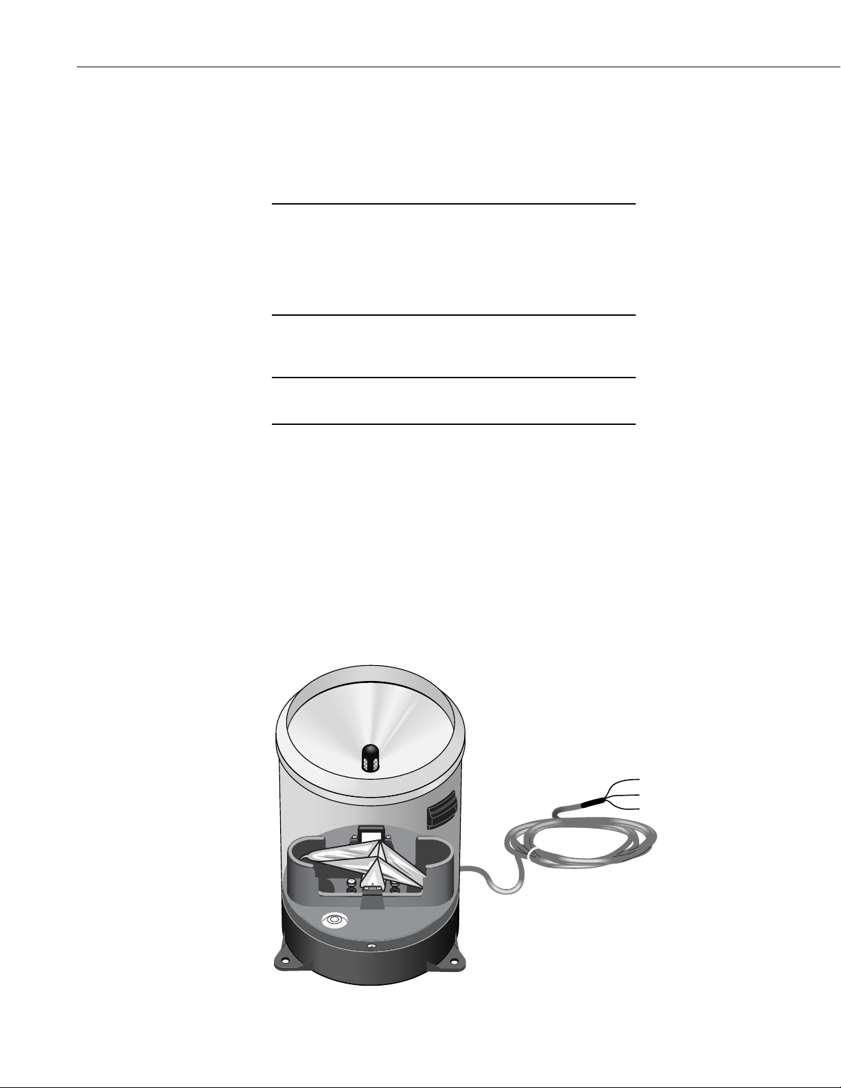
The TB4 and TB4MM tipping bucket rain gages are manufactured by
Hydrological Services Pty. Ltd. (Model TB4) and modified for use with
Campbell Scientific dataloggers.
These rain gages catch rainfall in the 7.87” (200 mm) diameter collection
funnel. When a full bucket of rainfall is collected, the tipping bucket assembly
tips and activates a reed switch. The switch closure is recorded by the
datalogger pulse channel. When the bucket tips, the water drains out the
screened fittings in the base of the gage.
Two models are available:
TB4 0.01 in. tip
TB4MM 0.2 mm tip
NOTE
Throughout this manual, both models are referred to as the TB4
unless specified otherwise.
The “-L” after the model TB4 Rain Gage indicates that the cable length is
specified when ordering.
The TB4 ships with:
(1) Allen Wrench from Original Mfg.
(1) Resource CD
The 260-953 Alter-Type Wind Screen can be used with the TB4 and TB4MM
to minimize the effects of strong winds.
2. Specifications
Funnel: 7.87 in (200 mm)
Drain Fittings: Accept 12 mm ID tubing
Measurement Range: 0 to 19.7 in/hr
(0 to 500 mm/hr)
Accuracy: Better than +2% @ 19.7in/hr (500 mm/hr)
Resolution: 0.01 in (0.254 mm) TB4
0.2 mm (0.008 in) TB4MM
Environmental Conditions:
Temperature: 0° to +70°C
Humidity: 0 to 100%
Temperature Specifications: -20 to +70°C
Siphon Capacity: 0.012 in (0.3mm)
Contact: Dual Reed Switch
1
Page 6
TB4 and TB4MM Rain Gage
NOTE
3. Installation
Capacity: 12 VA (0.5 amp max.)
Dimensions:
Weight: 4.41 pounds (2 kg)
Height: 13 in (330 mm)
Diameter: 7.9 in (200 mm)
®
The black outer jacket of the cable is Santoprene
compound was chosen for its resistance to temperature extremes,
moisture, and UV degradation. However, this jacket will
support combustion in air. It is rated as slow burning when
tested according to U.L. 94 H.B. and will pass FMVSS302.
Local fire codes may preclude its use inside buildings.
rubber. This
NOTE
3.1 Siting
3.2 Mounting
The 260-953 Alter-Type Wind Screen’s siting information and
installation procedure are provided in our 260-953 manual.
The rain gage should be mounted in a relatively level spot which is
representative of the surrounding area. The ground surface around the rain
gage should be natural vegetation or gravel. It should not be paved or
concrete.
For accurate measurements, the rain gage must be placed away from objects
that obstruct wind. The minimum distance should be 2 to 4 times the height of
the obstruction.
2
Page 7
TB4 and TB4MM Rain Gage
24”
8”
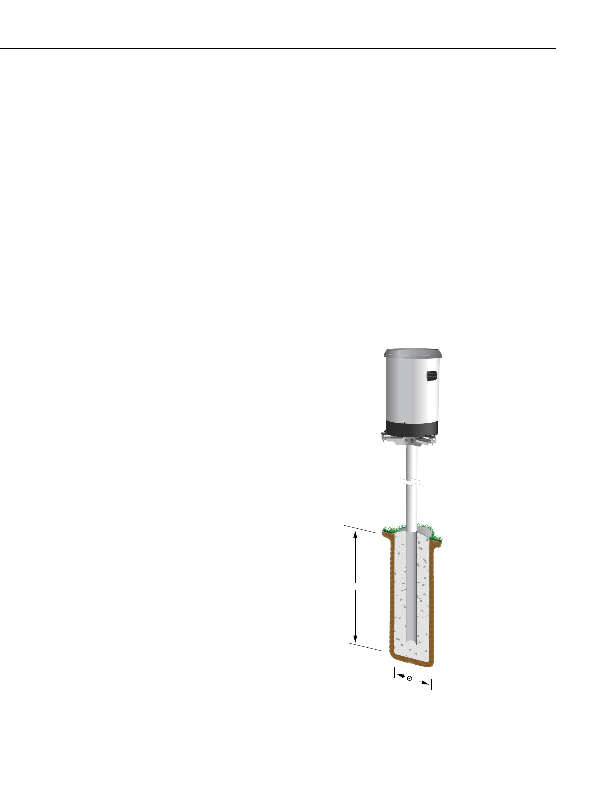
The rain gage is designed to mount on a flat surface. Three equally spaced
mounting pads are provided. The mounting pads are pre-drilled for three 3/8”
(M8) bolts on a 9.21” (234 mm) diameter bolt circle. The CM240 mounting
bracket is available from Campbell Scientific for installing the TB4. The
CM240 base helps level the rain gage, ensuring a more accurate measurement.
The base may be attached to a CM300-Series Mounting Pole or to a usersupplied 1.5 IPS (1.9” OD, unthreaded) pipe. The pipe should be long enough
to place the gage's orifice at a one-meter height. The rain gage should be high
enough to be above the average snow depth. The pole or pipe can be placed
directly into a concrete foundation, or attached to a concrete foundation using
J-bolts, or self-supporting with legs (see Figure 3-2). A concrete pad is
recommended. A typical rain gage installation is illustrated in Figure 3-1.
Remove the TB4 funnel from the base by removing the three screws and lifting
upward. Adjust the three nuts on the CM240 bracket to level the rain gage. A
bubble level is mounted on the TB4 base to facilitate leveling.
Remove the rubber shipping band and cardboard packing securing the tipping
bucket assembly. Tip the bucket several times to insure the tipping mechanism
is moving freely. Replace the housing assembly and tighten the three screws
to secure the housing to the base. Level the rain gage after mounting it.
FIGURE 3-1. Typical Rain Gage Installation
3
Page 8

TB4 and TB4MM Rain Gage
3.5”
1.5”
24”
4. Wiring
14”
FIGURE 3-2. Pedestal Base Options
Connections to Campbell Scientific dataloggers are given in Table 4-1. When
Short Cut for Windows software is used to create the datalogger program, the
sensor should be wired to the channels shown on the wiring diagram created
by Short Cut.
TABLE 4-1. Wiring for Pulse Channel Input
Color
Description
CR800
CR1000
CR3000
CR5000
CR510
CR500
CR10(X)
21X
CR7
CR23X
CR200 Series
Black Signal Pulse Channel Pulse Channel Pulse Channel P_SW
White Signal Return
Clear Shield
G
G
4
Page 9

TB4 and TB4MM Rain Gage
Dataloggers listed in Table 4-2 have the capability of counting switch closures
on some of their control ports. When a control port is used, the return from the
rain gage switch must be connected to +5 volts on the datalogger.
TABLE 4-2. Wiring for Control Port Input
Color
Description
CR800
CR1000
CR3000
CR500
CR510
CR10X
CR23X
Black Signal Control Port C2/P3 Control Port Control Port
White Signal Return 5 V 5 V 5 V 5 V
Clear Shield
G
The CR10 does not support the use of control port inputs with the Pulse Count
instruction.
Black
White
Clear
100
Ω
FIGURE 4-1. Rain Gage Schematic
In a long cable there is appreciable capacitance between the lines. A built up
charge could cause arcing when the switch closes, shortening switch life. A
100 ohm resistor is connected in series at the switch to prevent arcing by
limiting the current (Figure 4-1). This resistor is installed on all rain g ages
currently sold by Campbell Scientific.
5. Datalogger Programming
This section is for users who write their own datalogger programs. A
datalogger program to measure this sensor can be created using Campbell
Scientific’s Short Cut Program Builder software. You do not need to read this
section to use Short Cut.
The rain gage is measured using the Pulse Count instruction with the switch
closure configuration code. The multiplier used in the Pulse Count instruction
determines the units in which rainfall is reported.
TABLE 5-1. Multipliers
TB4 TB4MM
Inches
Millimeters
0.01 0.007874
0.254 0.2
5
Page 10

TB4 and TB4MM Rain Gage
5.1 Pulse Channel Example Programs
5.1.1 CR1000 Pulse Channel Example
'CR1000
'CR1000 Program for TB4
'Declare Variables and Units
Public Rain_mm
Units Rain_mm=mm
'Define Data Tables
DataTable(TB4_mm,True,-1)
DataInterval(0,60,Min,0)
Totalize(1,Rain_mm,IEEE4,0)
EndTable
'Main Program
BeginProg
Scan(1,Sec,1,0)
'TB4 Rain Gauge measurement Rain_mm:
PulseCount(Rain_mm,1,1,2,0,0.254,0)
'Call Data Tables and Store Data
CallTable(TB4_mm)
NextScan
EndProg
The following example programs use a pulse channel to read the output from
the rain gage.
Although this example is for the CR1000, Campbell Scientific’s CR800,
CR850, CR3000, and CR5000 are programmed similarly.
6
5.1.2 CR200(X) Series Pulse Channel Example
'CR200 Series
'TB4 program
'Declare Variables and Units
Public Rain_mm
Units Rain_mm=mm
'Define Data Tables
DataTable(TB4_mm,True,-1)
DataInterval(0,60,Min)
Totalize(1,Rain_mm,0)
EndTable
Page 11

'Main Program
BeginProg
Scan(10,Sec)
'TB4 Rain Gauge measurement Rain_mm:
PulseCount(Rain_mm,P_SW,2,0,0.254,0)
'Call Data Tables and Store Data
CallTable(TB4_mm)
NextScan
EndProg
5.1.3 CR10(X) Pulse Channel Example
The following example program uses a pulse channel to read the output from
the rain gage and will work with CR500, CR510, CR10(X), 21X and CR23X;
the CR7 is similar, but has an additional parameter in the Pulse Count
instruction to specify the slot that the Pulse Card is in.
;{CR10X}
;
;CR10X Program for TB4
;Rain (mm)
;
*Table 1 Program
01: 1 Execution Interval (seconds)
1: Pulse (P3)
1: 1 Reps
2: 1 Pulse Channel 1
3: 2 Switch Closure, All Counts
4: 1 Loc [ Rain_mm ]
5: .254 Multiplier
6: 0 Offset
2: If time is (P92)
1: 0 Minutes (Seconds --) into a
2: 60 Interval (same units as above)
3: 10 Set Output Flag High (Flag 0)
3: Set Active Storage Area (P80)
1: 1 Final Storage Area 1
2: 101 Array ID
4: Real Time (P77)
1: 1220 Year,Day,Hour/Minute (midnight = 2400)
5: Totalize (P72)
1: 1 Reps
2: 1 Loc [ Rain_mm ]
*Table 2 Program
02: 0.0000 Execution Interval (seconds)
*Table 3 Subroutines
End Program
TB4 and TB4MM Rain Gage
7
Page 12

TB4 and TB4MM Rain Gage
5.2 Control Port Example Programs
5.2.1 CR1000 Control Port Example
'CR1000
'CR1000 Program for TB4
'Declare Public Variables and Units
Public Rain_mm
Units Rain_mm=mm
DataTable (Rain,True,-1)
DataInterval (0,60,Min,0)
Totalize (1,Rain_mm,FP2,0)
EndTable
'Main Program
BeginProg
Scan (1,Sec,1,0)
PulseCount (Rain_mm,1,18,2,0,.254,0) ; Black wire connected to C8
CallTable (Rain)
NextScan
EndProg
Output Instruction 72, Totalize, is used in the output section of the program to
output the total rainfall over the output interval. This section should be
executed every scan and not placed in a subroutine or conditional statement.
The following examples measure a TB4 rain gage using a control port on the
datalogger. Wire the sensor as shown in Table 4-2.
Although this example is for the CR1000 datalogger, our CR800, CR850,
CR3000, and CR5000 are programmed similarly.
8
5.2.2 CR200(X) Series Control Port Example
'CR200
' A 20 kOhm pull up resistor is require to read a switch closure on C1 or C2
' as a Pulse Counter. The 20 kOhm resistor uses the battery voltage.
'Declare Public Variables and Units
Public Rain_mm
Units Rain_mm=mm
'Define Data Tables
DataTable (Rain,True,-1)
DataInterval (0,60,min)
Totalize (1,Rain_mm,0)
EndTable
Page 13

TB4 and TB4MM Rain Gage
'Main Program
BeginProg
Scan (1,Sec)
'TB4 Rain Gage measurement Rain-mm
PulseCount (Rain_mm,C2,2,0,.254,0) ; Black wire connected to C2
'Call Data Tables and Store Data
CallTable (Rain)
NextScan
EndProg
5.2.3 CR10X Control Port Example
Although this program is for the CR10X datalogger, our CR500, CR510, and
CR23X are programmed similarly.
;{CR10X}
*Table 1 Program
01: 1.0000 Execution Interval (seconds)
1: Pulse (P3)
1: 1 Reps
2: 8 Control Port 8 (switch closure only) ;Black wire connect to C8
3: 2 Switch Closure, All Counts
4: 1 Loc [ Rain_mm ]
5: .254 Multiplier
6: 0 Offset
2: If time is (P92)
1: 0 Minutes (Seconds --) into a
2: 60 Interval (same units as above)
3: 10 Set Output Flag High (Flag 0)
3: Set Active Storage Area (P80)
1: 1 Final Storage Area 1
2: 101 Array ID
4: Real Time (P77)
1: 1220 Year,Day,Hour/Minute (midnight = 2400)
5: Sample (P70)
1: 1 Reps
2: 1 Loc [ Rain_mm ]
*Table 2 Program
01: 0.0000 Execution Interval (seconds)
*Table 3 Subroutines
End Program
9
Page 14

TB4 and TB4MM Rain Gage
6. Troubleshooting
6.1 Precipitation
Symptom: No Precipitation
1. Check that the sensor is wired to the Pulse Channel specified by the pulse
count instruction.
2. Verify that the Configuration Code (Switch Closure), and Multiplier and
Offset parameters for the Pulse Count instruction are correct for the
datalogger type.
3. Disconnect the sensor from the datalogger and use an ohm meter to do a
continuity check of the switch. The resistance measured at the terminal
block on the inside of the bucket between the black and white leads
should vary from infinite (switch open) when the bucket is tipped, to less
than an ohm when the bucket is balanced.
7. Maintenance
During each site visit, remove any debris, insects, sediment, etc. from the
collection funnel, debris screen, siphoning mechanism, or tipping bucket
assembly.
Verify the tipping bucket assembly moves freely, and that the datalogger
records each bucket tip.
7.1 Dismantling for Cleaning
The following items should be checked regularly for cleanliness:
• Catch filter (see Figure 7-3)
• Siphon (see Figure 7-3)
• Interior of bucket (see Figure 7-1)
• Top surface of adjusting screws (see Figure 7-1)
• Housing locking screws; lightly lubricate after cleaning (see Figure 7-1)
• All insect screens (see Figure 7-1)
10
Page 15

TB4 and TB4MM Rain Gage
To access the above components, dismantle the TB4 using the following
procedure:
1. Remove the housing assembly from the base by loosening the three
locking screws and lifting the housing upward.
Bullseye Level
Reed Switch Assembly
Bucket Assembly
Housing Screw
FIGURE 7-1. Components of TB4 Base
11
Page 16

TB4 and TB4MM Rain Gage
2. Separate the filter/siphon assembly from the funnel by pushing the filter
while pulling the siphon (see Figure 7-2).
Do not twist while
pushing and pulling.
CAUTION
Do not twist the filter/siphon assembly while pushing and
pulling.
To dismantle the filter and siphon assembly,
push filter and pull siphon at the same time.
Do not twist.
Push Filter
Pull
Siphon
12
FIGURE 7-2. Dismantling the Filter/Siphon Assembly
Page 17

TB4 and TB4MM Rain Gage
3. Disassemble the filter/siphon assembly by doing the following (see Figure
7-3):
(a) Unscrew nut
(b) Lightly press stem down on surface until stem pops out of siphon
body.
(c) Remove stem from siphon body.
(d) Unscrew cap
(e) Clean all items
Filter Cover
Filter Screen
Stem Cap
Stem
O Ring
Siphon Body
Brass Nut
FIGURE 7-3. Filter/Siphon Assembly
13
Page 18

TB4 and TB4MM Rain Gage
7.2 Reassembling the TB4
1. Screw cap on stem, finger tighten only (see Figure 7-2).
2. Push stem into siphon body (see Figure 7-2).
3. Replace nut and tighten (see Figure 7-2).
CAUTION
CAUTION
Do not over tighten.
4. Push filter/siphon assembly back into place (see Figure 7-4).
Do not twist the filter/siphon assembly while putting it back
into place.
To re-assemble,
push the
filter/siphon
assembly back
in place.
Do not twist.
14
FIGURE 7-4. Reassembling the TB4
5. Place the housing assembly back onto the base and tighten the three
screws that secure the housing onto the base.
Page 19

8. Calibration
TB4 and TB4MM Rain Gage
The sensor is factory calibrated; recalibration is not required unless damage
has occurred or the adjustment screws have loosened. Nevertheless, the
following calibration check is recommended once every 12 months:
Field Calibration Check:
a. Remove the housing assembly from the base by removing the three
screws and lifting upward on the housing.
b. Check the bubble level to verify the rain gage is level.
c. Pour water through the inner funnel to wet the two bucket surfaces.
Using a graduated cylinder, slowly pour 314 cc (19.16 in
a 15 minute period, into the collection funnel. This volume of water is
equal to .39 inches of rainfall (10 mm).
d. After the water has passed through the rain gage, the tipping bucket
should have tipped 39 times for the TB4 or 50 times for the TB4MM.
e. If the rain gage fails to record the correct number of tips, return the unit to
Campbell Scientific for recalibration.
Factory Calibration
If factory calibration is required, contact Campbell Scientific to obtain an
RMA (see Warranty and Assistance in the front of the manual).
3
) of water, over
15
Page 20

TB4 and TB4MM Rain Gage
16
Page 21

Page 22

Campbell Scientific Companies
Campbell Scientific, Inc. (CSI)
815 West 1800 North
Logan, Utah 84321
UNITED STATES
www.campbellsci.com • info@campbellsci.com
Campbell Scientific Africa Pty. Ltd. (CSAf)
PO Box 2450
Somerset West 7129
SOUTH AFRICA
www.csafrica.co.za • cleroux@csafrica.co.za
Campbell Scientific Australia Pty. Ltd. (CSA)
PO Box 444
Thuringowa Central
QLD 4812 AUSTRALIA
www.campbellsci.com.au • info@campbellsci.com.au
Campbell Scientific do Brazil Ltda. (CSB)
Rua Luisa Crapsi Orsi, 15 Butantã
CEP: 005543-000 São Paulo SP BRAZIL
www.campbellsci.com.br • suporte@campbellsci.com.br
Campbell Scientific Canada Corp. (CSC)
11564 - 149th Street NW
Edmonton, Alberta T5M 1W7
CANADA
www.campbellsci.ca • dataloggers@campbellsci.ca
Campbell Scientific Centro Caribe S.A. (CSCC)
300 N Cementerio, Edificio Breller
Santo Domingo, Heredia 40305
COSTA RICA
www.campbellsci.cc • info@campbellsci.cc
Campbell Scientific Ltd. (CSL)
Campbell Park
80 Hathern Road
Shepshed, Loughborough LE12 9GX
UNITED KINGDOM
www.campbellsci.co.uk • sales@campbellsci.co.uk
Campbell Scientific Ltd. (France)
Miniparc du Verger - Bat. H
1, rue de Terre Neuve - Les Ulis
91967 COURTABOEUF CEDEX
FRANCE
www.campbellsci.fr • info@campbellsci.fr
Campbell Scientific Spain, S. L.
Avda. Pompeu Fabra 7-9, local 1
08024 Barcelona
SPAIN
www.campbellsci.es • info@campbellsci.es
Please visit www.campbellsci.com to obtain contact information for your local US or International representative.
 Loading...