

Page 1
Product Manual
Revision: 03/2021
Copyright © 1993 – 2021
Campbell Scientific
CSL I.D - 1367
Page 2

Guarantee
This equipment is guaranteed against defects in materials and workmanship.
We will repair or replace products which prove to be defective during the
guarantee period as detailed on your invoice, provided they are returned to us
prepaid. The guarantee will not apply to:
Equipment which has been modified or altered in any way without the
written permission of Campbell Scientific
Batteries
Any product which has been subjected to misuse, neglect, acts of God or
damage in transit.
Campbell Scientific will return guaranteed equipment by surface carrier
prepaid. Campbell Scientific will not reimburse the claimant for costs incurred
in removing and/or reinstalling equipment. This guarantee and the Company’s
obligation thereunder is in lieu of all other guarantees, expressed or implied,
including those of suitability and fitness for a particular purpose. Campbell
Scientific is not liable for consequential damage.
Please inform us before returning equipment and obtain a Repair Reference
Number whether the repair is under guarantee or not. Please state the faults as
clearly as possible, and if the product is out of the guarantee period it should
be accompanied by a purchase order. Quotations for repairs can be given on
request. It is the policy of Campbell Scientific to protect the health of its
employees and provide a safe working environment, in support of this policy a
“Declaration of Hazardous Material and Decontamination” form will be
issued for completion.
When returning equipment, the Repair Reference Number must be clearly
marked on the outside of the package. Complete the “Declaration of
Hazardous Material and Decontamination” form and ensure a completed copy
is returned with your goods. Please note your Repair may not be processed if
you do not include a copy of this form and Campbell Scientific Ltd reserves
the right to return goods at the customers’ expense.
Note that goods sent air freight are subject to Customs clearance fees which
Campbell Scientific will charge to customers. In many cases, these charges are
greater than the cost of the repair.
Campbell Scientific Ltd,
80 Hathern Road,
Shepshed, Loughborough, LE12 9GX, UK
Tel: +44 (0) 1509 601141
Fax: +44 (0) 1509 270924
Email: support@campbellsci.co.uk
www.campbellsci.co.uk
Page 3

About this manual
Please note that this manual was originally produced by Campbell Scientific Inc. primarily for the North
American market. Some spellings, weights and measures may reflect this origin.
Some useful conversion factors:
Area: 1 in2 (square inch) = 645 mm2
Length: 1 in. (inch) = 25.4 mm
1 ft (foot) = 304.8 mm
1 yard = 0.914 m
1 mile = 1.609 km
In addition, while most of the information in the manual is correct for all countries, certain information
is specific to the North American market and so may not be applicable to European users.
Differences include the U.S standard external power supply details where some information (for
example the AC transformer input voltage) will not be applicable for British/European use. Please note,
however, that when a power supply adapter is ordered it will be suitable for use in your country.
Reference to some radio transmitters, digital cell phones and aerials may also not be applicable
according to your locality.
Some brackets, shields and enclosure options, including wiring, are not sold as standard items in the
European market; in some cases alternatives are offered. Details of the alternatives will be covered in
separate manuals.
Part numbers prefixed with a “#” symbol are special order parts for use with non-EU variants or for
special installations. Please quote the full part number with the # when ordering.
Mass: 1 oz. (ounce) = 28.35 g
1 lb (pound weight) = 0.454 kg
Pressure: 1 psi (lb/in2) = 68.95 mb
Volume: 1 UK pint = 568.3 ml
1 UK gallon = 4.546 litres
1 US gallon = 3.785 litres
Recycling information
At the end of this product’s life it should not be put in commercial or domestic refuse but
sent for recycling. Any batteries contained within the product or used during the
products life should be removed from the product and also be sent to an appropriate
recycling facility.
Campbell Scientific Ltd can advise on the recycling of the equipment and in some cases
arrange collection and the correct disposal of it, although charges may apply for some
items or territories.
For further advice or support, please contact Campbell Scientific Ltd, or your local agent.
Campbell Scientific Ltd, 80 Hathern Road, Shepshed, Loughborough, LE12 9GX,
UK Tel: +44 (0) 1509 601141 Fax: +44 (0) 1509 270924
Email: support@campbellsci.co.uk
www.campbellsci.co.uk
Page 4

Safety
DANGER — MANY HAZARD S ARE ASSOCIATED WITH INSTALLING, USING, M AINTAINING, AND WORKING ON
OR AROUND TRIPODS, TOWERS, AND ANY ATTACHMENTS TO TRIPODS AND TOWERS SUCH AS SENSORS,
CROSSARMS, ENCLOSURES, ANTENNAS, ETC. FAILURE TO PROPERLY AND COM P LE TE LY ASS E M BLE ,
INSTALL, OPERATE, USE, AND MAINTAIN TRIPODS, TOWERS, AND ATTACHMENTS, AND FAILURE TO HEED
WARNINGS, INCREASES THE RISK OF DEATH, ACCIDENT, SERIOUS INJURY, PROPERTY DAMAGE, AND
PRODUCT FAILURE. TAKE ALL REASONABLE PRECAUTIONS TO AVOID THESE HAZARDS. CHECK WITH YOUR
ORGANIZATION'S SAFETY COORDINATOR (OR POLICY) FOR PROCEDURES AND REQUIRED PROTECTIVE
EQUIPMENT PRIOR TO PERFORMING ANY WORK.
Use tripods, towers, and attachments to tripods and towers only for purposes for which they are designed. Do not
exceed design limits. Be familiar and comply with all instructions provided in product manuals. Manuals are
available at www.campbellsci.eu or by telephoning +44(0) 1509 828 888 (UK). You are responsible for conformance
with governing codes and regulati ons, including safety regulati ons, and the integrity and locati on of structures or land
to which towers, tripods, and any attachments are attached. Installation sites should be evaluated and approved by a
qualified engineer. If questions or co ncerns arise regarding installation, use, or maintenance of tripods, towers,
attachments, or electrical connections, consult with a licensed and qualified engineer or electrician.
General
• Prior to performing site or installation work, obtain required approvals and permits. Comply with all
governing structure-height regulations, such as those of the FAA in the USA.
• Use only qualified personnel for installation, use, and maintenance of tripods and towers, and any
attachments to tripods and towers. The use of licensed and qualified contractors is highly recommended.
• Read all applicable instructions carefully and understand procedures thoroughly before beginning work.
• Wear a hardhat and eye protection, and take other appropriate safety precautions while working on or
around tripods and towers.
• Do not climb tripods or towers at any time, and prohibit climbing by other persons. Take reasonable
precautions to secure tripod and tower sites from trespassers.
• Use only manufacturer recommended parts, materials, and tools.
Utility and Electrical
• You can be killed or sustain serious bodily injury if the tripod, tower, or attachments you are installing,
constructing, using, or maintaining, or a tool, stake, or anchor, come in contact with overhead o
nderground utility lines.
u
• Maintain a distance of at least one-and-one-half times structure height, or 20 feet, or the distance
r
equired by applicable law, whichever is greater, between overhead utility lines and the structure (tripod,
tower, attachments, or tools).
• Prior to performing site or installation work, inform all utility companies and have all underground utilities
marked.
• Comply with all electrical codes. Electrical equipment and related grounding devices should be installed
by a licensed and qualified electrician.
r
Elevated Work and Weather
• Exercise extreme caution when performing elevated work.
• Use appropriate equipment and safety practices.
• During installation and maintenance, keep tower and tripod sites clear of un-trained or non-essential
personnel. Take precautions to prevent elevated tools and objects from dropping.
• Do not perform any work in inclement weather, including wind, rain, snow, lightning, etc.
Maintenance
• Periodically (at least yearly) check for wear and damage, including corrosion, stress cracks, frayed cables,
loose cable clamps, cable tightness, etc. and take necessary corrective actions.
• Periodically (at least yearly) check electrical ground connections.
WHILE EVERY ATTEMPT IS MADE TO EMBODY THE HIGHEST DEGREE OF SAFETY IN ALL CAMPBELL
SCIENTIFIC PRODUCTS, THE CUSTOMER ASSUMES ALL RISK FROM ANY INJURY RESULTING FROM IMPROPER
INSTALLATION, USE, OR MAINTENANCE OF TRIPODS, TOWERS, OR ATTACHMENTS TO TRIPODS AND TOWERS
SUCH AS SENSORS, CROSSARMS, ENCLOSURES, ANTENNAS, ETC.
Page 5

Table of contents
1. Introduction 1
2. Precautions 2
3. Initial inspection 3
4. QuickStart 6
4.1 User-supplied tools 6
4.2 Supplies for power and communications options 8
5. Siting and exposure 10
5.1 Wind speed and direction 10
5.2 Temperature and relative humidity 11
5.3 Solar radiation 11
6. Installation 12
6.1 Base foundation installation 12
6.2 Pole installation 14
6.2.1 Pole grounding 16
6.3 Enclosure installation 17
6.4 AC power installation procedure 18
6.5 Crossarm installation procedure 20
6.6 Sensor installation 21
6.6.1 RH and temperature radiation shield installation procedure 22
6.6.2 034B Wind Sensor (wind sensor option -MW) 24
6.6.3 WindSonic 2-D Ultrasonic Wind Sensor (wind sensor option -GW) 26
6.6.3.1 Changing the jumper 26
6.6.3.2 WindSonic attachment to crossarm 28
6.6.4 Rain gauge 30
6.6.5 Pyranometer 31
6.6.6 Sensor connections 33
6.6.7 Sensor verification and clock set 34
6.7 Communications peripherals 35
6.7.1 Direct connect to T107 station 35
6.7.2 Phone modem 36
Table of Contents - i
Page 6

6.7.2.1 Internal installation of phone modem 37
6.7.2.2 External installation of phone modem 38
6.7.3 Short-haul modem 38
6.7.3.1 Internal installation of short haul modem 38
6.7.3.2 External installation of short haul modem 40
6.7.4 Radio 41
6.7.4.1 Example radio configuration and power usage 42
6.7.4.2 Internal installation of the radio 43
6.7.4.3 External installation of the radio 44
6.7.4.4 Base radio installation 50
6.8 Lightning rod installation 51
6.9 Solar panel installation 53
6.10 Battery installation 55
6.11 Restraining cables 56
6.12 Sealing and desiccating the enclosure 58
6.13 T107 software 59
7. Maintenance and troubleshooting 61
7.1 Maintenance 61
7.1.1 Pole maintenance 61
7.1.2 Power supply maintenance 61
7.1.3 Desiccant 61
7.1.4 Sensor maintenance 62
7.1.4.1 Procedure for removing RH chip 65
7.1.5 Data logger module 65
7.2 Troubleshooting 66
7.2.1 No response using the CR1000KD keypad 66
7.2.2 No response from data logger when using a communications peripheral 67
7.2.3 NAN, ±INF, or unreasonable results displayed in a variable or stored in a data
table 68
7.2.4 WindSonic1-ET diagnostic codes 68
8. Schematics of connectors 69
8.1 Sensor schematics 69
8.2 Power schematics 73
8.3 Communications modems schematics 74
Table of Contents - ii
Page 7

9. References
75
Appendix A. Wind Direction Sensor Orientation
A.1 Determining True North and Sensor Orientation 78
Appendix B. PS24 24 Ah power supply with 10 x 12 inch enclosure 80
B.1 PS24 components 80
B.2 PS24 installation 82
Appendix C. T107 maintenance log 92
76
Table of Contents - iii
Page 8

1. Introduction
The T107 is an automated weather station designed for irrigation scheduling in turf grass and
commercial agriculture applications. A properly programmed station or software calculates
potential evapotranspiration (ETo), which is the amount of water lost from the soil due to
evaporation and plant transpiration. Calculating the evapotranspiration rate can aid in the
development of an irrigation schedule that provides sufficient water without overwatering.
Section1. Introduction 1
Page 9

2. Precautions
l READ AND UNDERSTAND the Safety section at the back of this manual.
l DANGER: If any part of the weather station comes in contact with power lines, you could
be killed. Contact local utilities for the location of buried utility lines before digging or
driving ground rods.
l Avoid dangerous electrical accidents when using the AC power option by locating the
transformer remotely and burying a low voltage line to the station. The low voltage will
carry up to 152m (500ft) on an 18 AWG power cable.
l Carefully handle the T107 components during transport, installation, and cleaning.
l Leave the 034B wind vane in the protective cardboard sleeve until it’s ready to be installed.
l Ensure to remove the yellow cap from the RH and temperature sensor, the red or green cap
from the pyranometer, and the rubber band from the tipping bucket mechanism. Save the
caps for shipping or storing the sensors.
l When connecting cables to the enclosure panel, ensure that each plug is completely
seated on the connector and the locking ring is turned a quarter revolution clockwise.
Failure to seat the plug completely could cause corrosion and water damage to both the
enclosure and the cable.
l WARNING: Misuse of the lithium battery in the data logger or installing this lithium battery
improperly can cause severe injury. It is a fire, explosion, and severe burn hazard! Do not
recharge, disassemble, heat above 100 °C (212 °F), solder directly to the cell, incinerate, nor
expose contents to water. Lithium batteries need to be disposed of properly. Refer to Data
logger module (p. 65) for more information.
Section2. Precautions 2
Page 10
3. Initial inspection
Immediately upon receipt of your shipment:
1. Open shipping carton(s). Solar panel and radio frequency (RF) items (if any) may be packed
in a separate box.
2. Set the large weather station carton down lengthwise on a floor or table top.
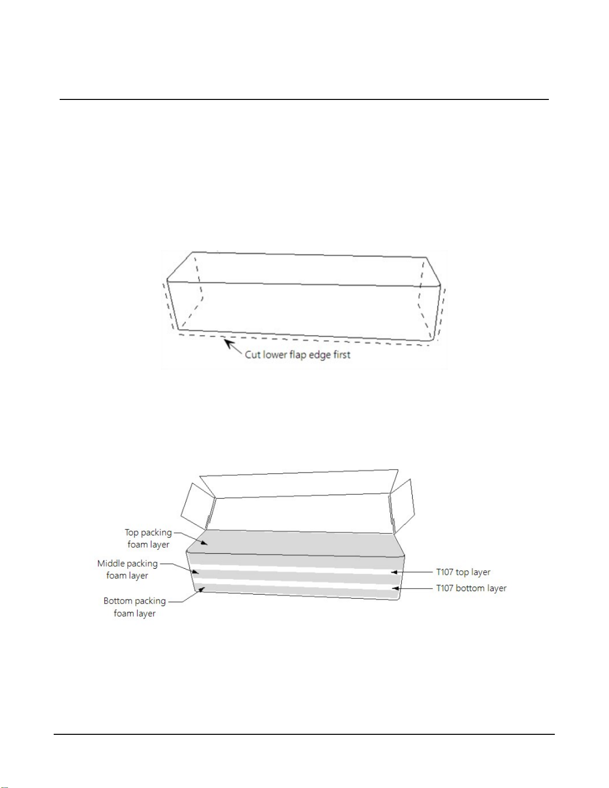
3. Position the box as shown in FIGURE 3-1 (p. 3).
4. Cut the tape along the edge of the lower flap first (FIGURE 3-1 (p. 3)).
FIGURE 3-1. Cut flap packing tape
5. Cut the tape around the remaining flaps ensuring to only cut one layer deep.
6. Lift up the cardboard flaps exposing the top layer of foam (FIGURE 3-2 (p. 3)).
FIGURE 3-2. Shipping box packaging
Section3. Initial inspection 3
Page 11
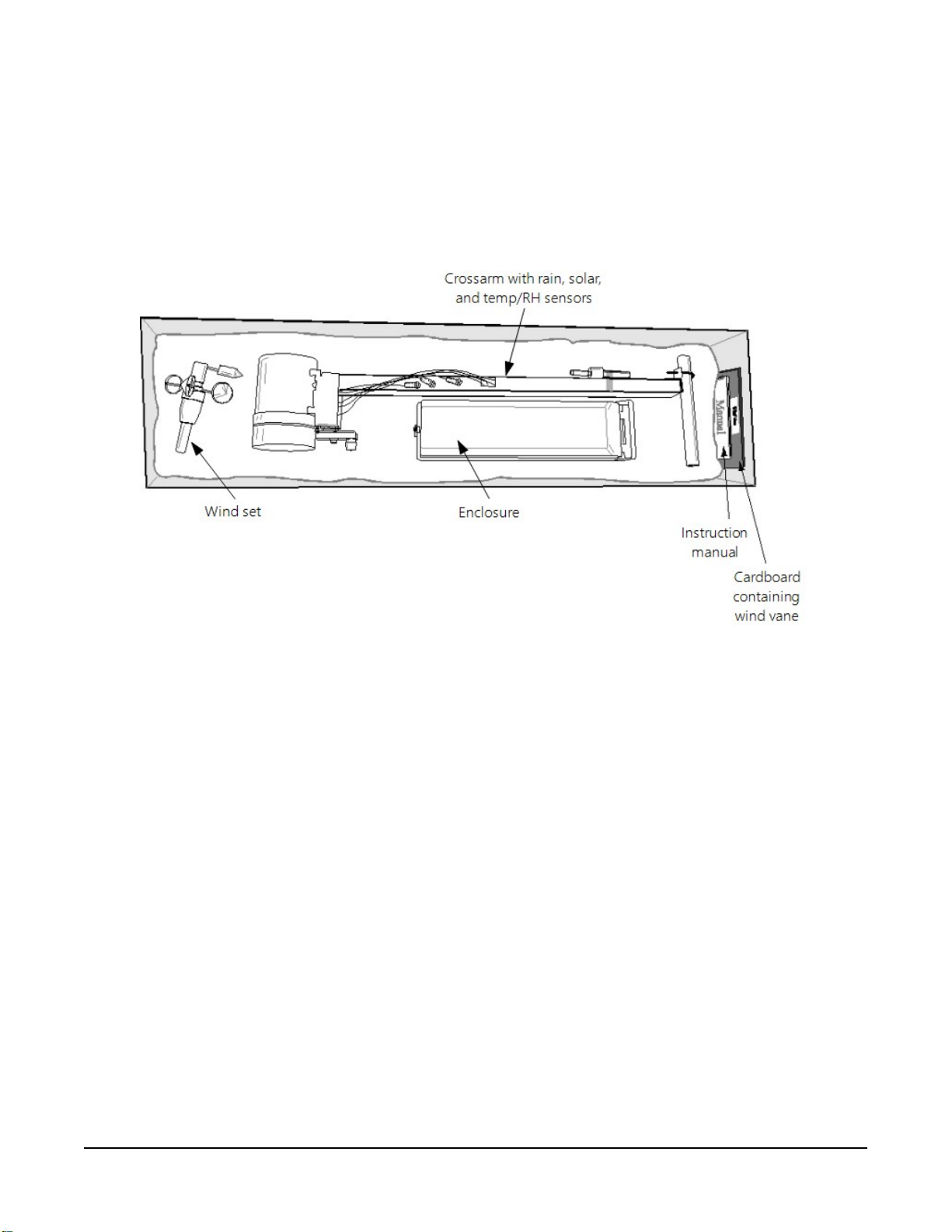
7. Check contents against invoice and shipping checklist (FIGURE 3-3 (p. 4), FIGURE 3-4 (p.
5)) and contact your Toro representative immediately about any shortages.
8. Securely tape box shut if transporting entire station to another site.
9. If at the main site, remove communications components that are installed at the calling
computer. Repackage remaining components for transport to field site.
FIGURE 3-3. T107 with the Met One 034B-ETM Wind Sensor, top layer
Section3. Initial inspection 4
Page 12
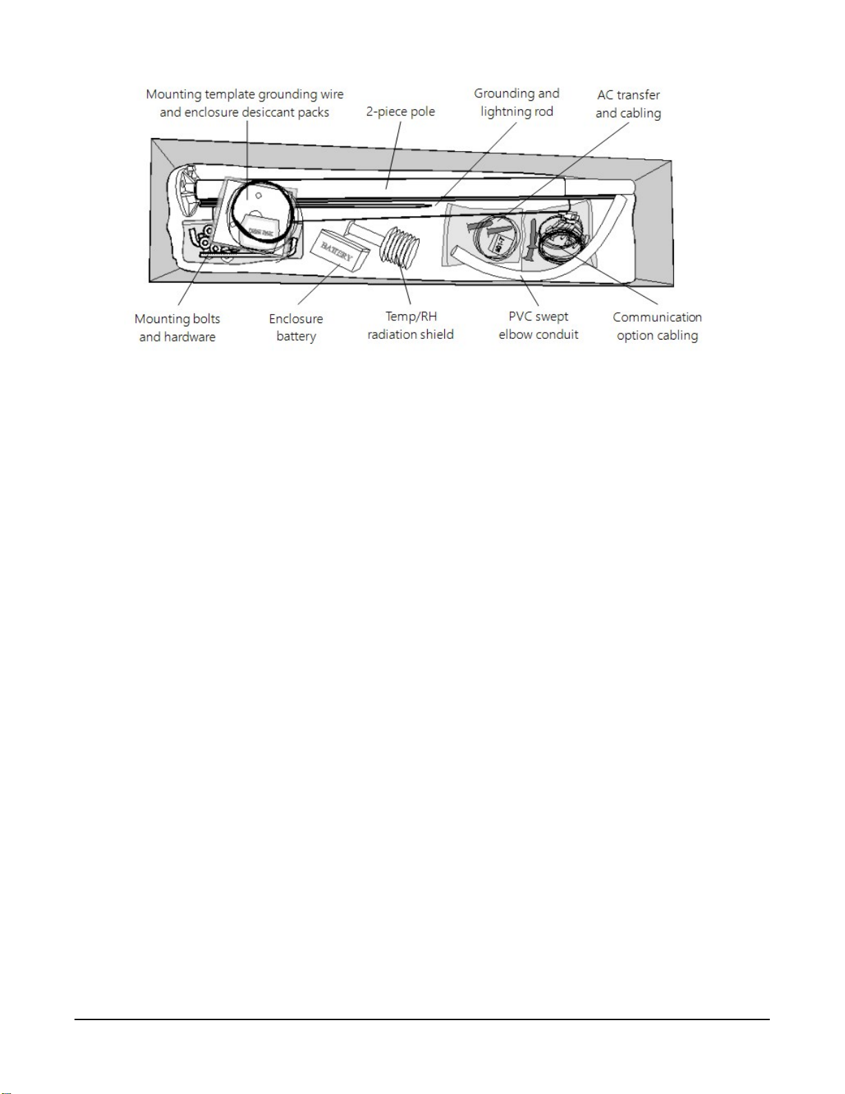
FIGURE 3-4. T107, bottom layer
Section3. Initial inspection 5
Page 13

4. QuickStart
In the office, several days prior to the planned installation date, do the following:
1. Collect tools (User-supplied tools (p. 6))
2. Research site (Siting and exposure (p. 10))
3. Install data logger support software (T107 software (p. 59))
Once on site, do the following:
1. Locate suitable site (Siting and exposure (p. 10)).
2. Prepare concrete base and allow the concrete base to cure a minimum of seven days (Base
foundation installation (p. 12))
3. Install the T107 pole (Pole installation (p. 14)).
4. Place instrumentation enclosure on the T107 pole, slide the enclosure to the top of the
pole, and secure it with the correct orientation (Enclosure installation (p. 17)).
5. Install the crossarm and sensors (Crossarm installation procedure (p. 20) and Sensor
installation (p. 21)).
4.1 User-supplied tools
The following tools are used for the base and pole installation.
Shovel
Rake
Open end wrenches: 10 mm (3/8 in), 11 mm (7/16 in), 13 mm (1/2 in), two 14 mm (9/16 in)
Magnetic compass
2 m (6 ft) step ladder
Tape measure: 4 to 6 m (12 to 20 ft)
Claw hammer
Level: 60 to 90 cm (24 in to 36 in)
Hand saw
Materials for concrete form:
Section4. QuickStart 6
Page 14

(4) 2.5 cm x 5 cm x 30 cm (1 in x 2 in x 12 in) stakes
(2) 5 cm x 10 cm x 240 cm (2 in x 4 in x 96 in) lumber
(12) 8p double-head nails
(8) 16p double-head nails
6 m (20 ft) form wire
0.5 m (0.5 yard) concrete
Concrete trowel, edger
Electrical fish tape or 6 m (20 ft) of small diameter rope
Wheelbarrow
The following tools are needed for instrumentation and maintenance.
Lock and key for enclosure
Magnetic declination angle
Magnetic compass
Straight bit screwdrivers (small, medium, large)
Phillips-head screwdrivers (small, medium)
Small diagonal side-cutters
Needle-nose pliers
Wire strippers
Pocket knife
Calculator
Volt / ohm meter
Electrical tape
2 m (6 ft) step ladder
Station manuals
Station log and pen
Open end wrenches: 10 mm (3/8 in), 11 mm (7/16 in), 13 mm (1/2 in), 14 mm (9/16 in), 24 mm
(15/16 in)
Socket wrench and 11 mm (7/16 in) deep well socket
Adjustable wrench
Pliers
Section4. QuickStart 7
Page 15
Conduit and associated tools (as required)
Felt-tipped marking pen
Claw hammer
Pipe wrench, 305 mm (12 in)
Handheld drill/driver with 10 mm (3/8 inch) hex driver bit
Drill with 6 mm (7/32 in) drill bit
4.2 Supplies for power and communications options
AC Power
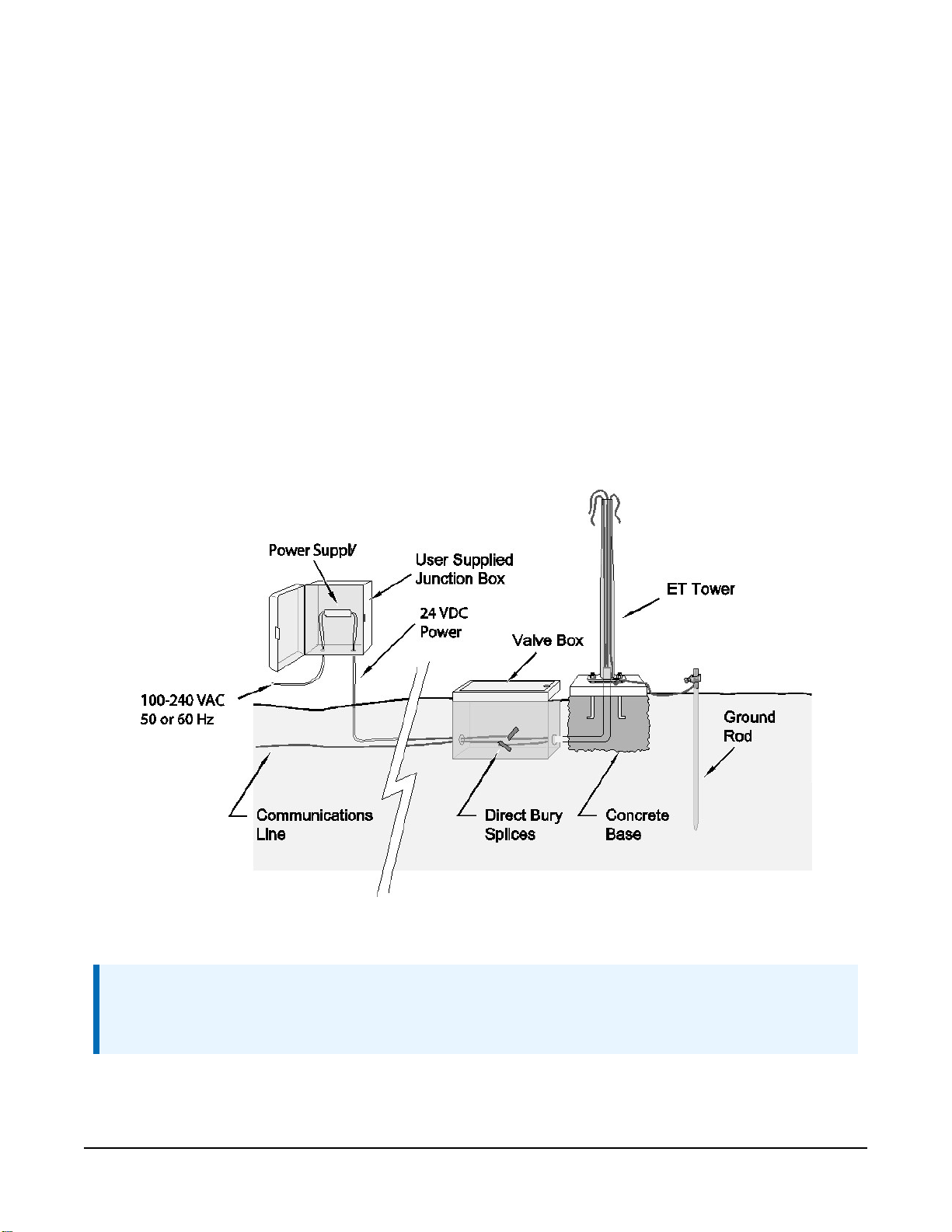
Wire, conduit, and junction boxes as needed (FIGURE 4-1 (p. 8)).
FIGURE 4-1. T107 pole installation with currently-available AC power option
NOTE:
User supplies valve box at base of station and weatherproof enclosure for transformer
(FIGURE 4-1 (p. 8)).
Section4. QuickStart 8
Page 16

Phone Modem
Phone modem at the central computer.
Dedicated single twisted pair with shield phone line to the weather station valve/junction box
(FIGURE 4-1 (p. 8)).
Short-Haul Modem
Direct burial cable with a minimum of two-twisted pairs with shield (minimum five conductors
total) to travel from the weather station to the central computer junction box. Direct burial
armored cable may be required for rocky soils or rodents (Anixter pn F-02P22BPN (phone 847677-2600)) or equivalent type cable (FIGURE 4-1 (p. 8)).
Radio
Antenna for the T107 station (Yagi antenna recommended). PS24 Power Supply and mounting
kit with hangar if not using AC power (PS24 24 Ah power supply with 10 x 12 inch enclosure (p.
80)).
Section4. QuickStart 9
Page 17
5. Siting and exposure
DANGER:
If any part of the weather station comes in contact with power lines, you could be killed.
Contact local utilities for the location of buried utility lines before digging or driving ground
rods.
Selecting an appropriate site for the weather station is critical to obtain accurate meteorological
data. In general, the site should be representative of the general area of interest, and away from
the influence of obstructions such as buildings and trees.
The weather station should not be located where sprinkler irrigation water will strike sensors or
instrument enclosure.
Some general guidelines for site selection are listed below, which were condensed from EPA
(1988), WMO (1983), and AASC (1985) publications. See References (p. 75).
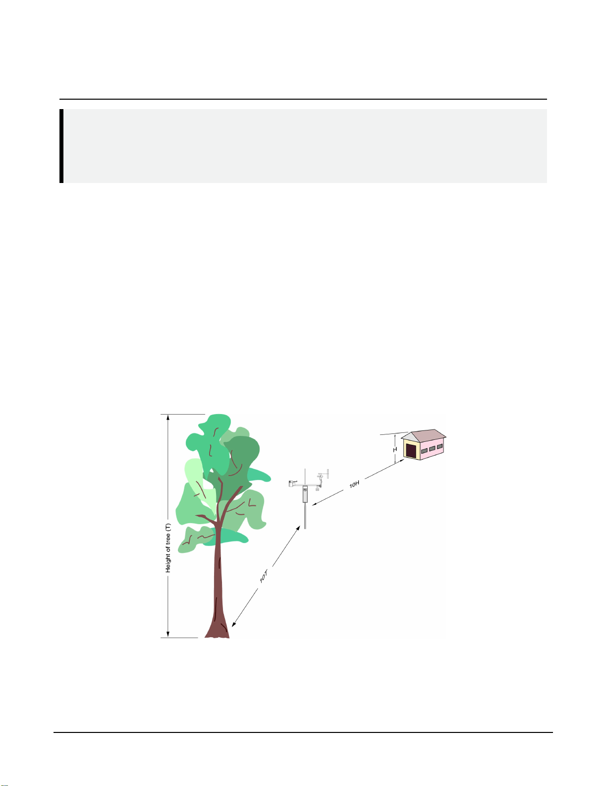
5.1 Wind speed and direction
Wind sensors should be located over open, level terrain, and at a distance of at least ten times
(EPA) the height of any nearby building, tree, or other obstruction (FIGURE 5-1 (p. 10)).
FIGURE 5-1. Effect of structure on wind flow
Section5. Siting and exposure 10
Page 18

5.2 Temperature and relative humidity
Sensors should be located over an open, level area at least 9m (29.5ft) (EPA) in diameter. The
surface should be covered by short grass, or where grass does not grow, the natural earth surface.
Sensors should be located at a distance of at least four times the height of any nearby
obstruction and at least 30m (98.43ft) (EPA) from large paved areas. Sensors should be
protected from thermal radiation and adequately ventilated.
Situations to avoid include:
l large industrial heat sources
l rooftops
l steep slopes
l sheltered hollows
l high vegetation
l shaded areas
l swamps
l areas where snow drifts occur
l low places holding standing water after rains
5.3 Solar radiation
Pyranometers should be located to avoid shadows on the sensor at any time. Mounting it on the
southernmost (northern hemisphere) portion of the weather station will minimize the chance of
shading from other weather station structures. Reflective surfaces and sources of artificial
radiation should be avoided.
Section5. Siting and exposure 11
Page 19

6. Installation
6.1 Base foundation installation 12
6.2 Pole installation 14
6.3 Enclosure installation 17
6.4 AC power installation procedure 18
6.5 Crossarm installation procedure 20
6.6 Sensor installation 21
6.7 Communications peripherals 35
6.8 Lightning rod installation 51
6.9 Solar panel installation 53
6.10 Battery installation 55
6.11 Restraining cables 56
6.12 Sealing and desiccating the enclosure 58
6.13 T107 software 59
6.1 Base foundation installation
The following components included with the T107 are used for this installation procedure:
(3) 16 mm (5/8 in) anchor L-bolts
(9) 16 mm (5/8 in) nuts
(1) anchor template
The pole attaches to a user-supplied concrete foundation constructed as shown in FIGURE 6-1 (p.
13).
Section6. Installation 12
Page 20
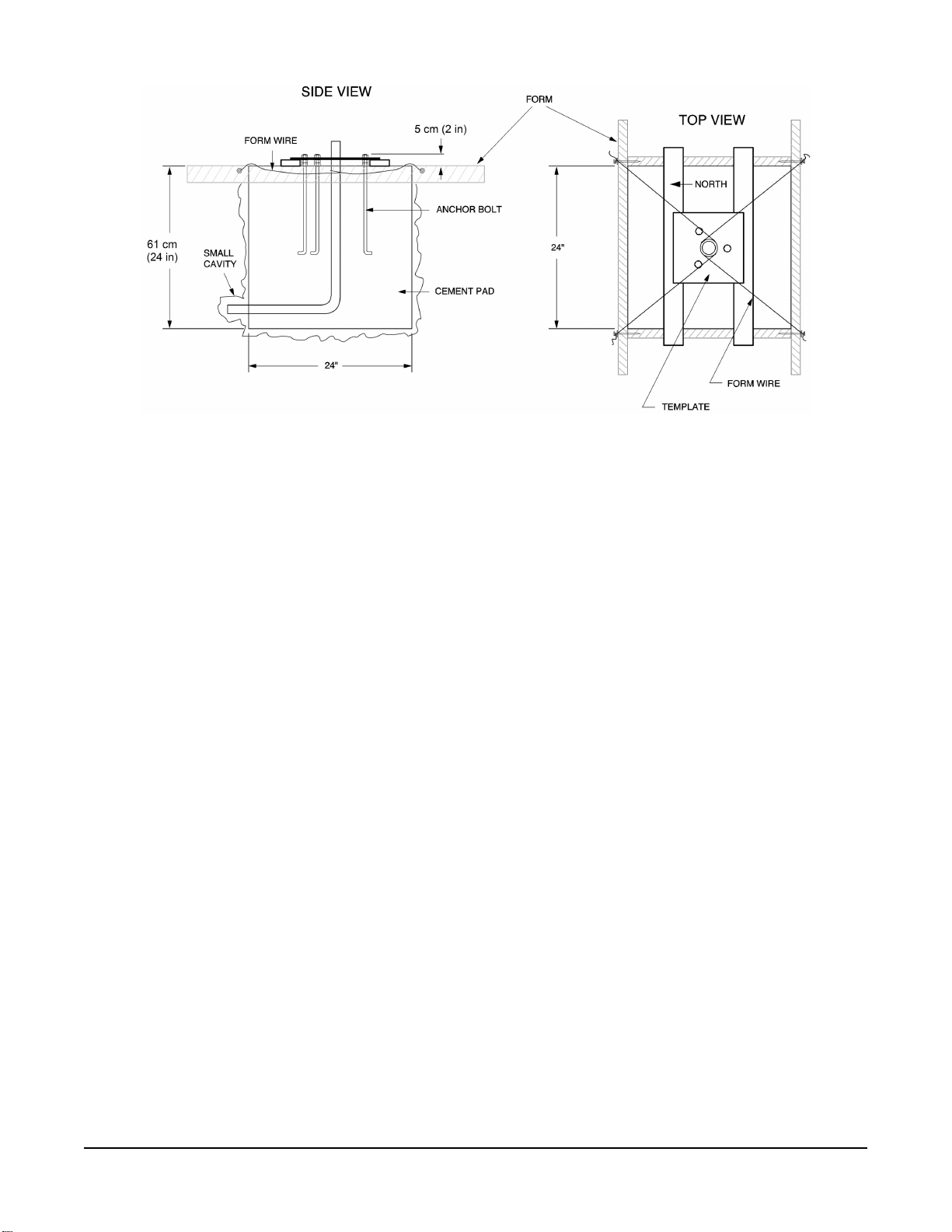
FIGURE 6-1. T107 pole base installation
1. Construct the concrete form with 5 cm x 10 cm (2 in x 4 in) lumber and 16p nails.
2. Assemble the template and anchor bolts. For each bolt, place two nuts below and one nut
above the template.
3. Clear an area large enough to set the form at the desired elevation.
4. Dig a hole 0.6 m x 0.6 m x 0.6 m (2 ft x 2 ft x 2 ft). Lighter soils may require a deeper hole.
5. About 50 cm (20 in) below the top of the hole, gouge a small cavity in one wall of the hole.
The cavity should be about 10 cm (4 in) deep and just large enough in diameter to insert
one end of the conduit. Make certain the cavity points in the direction from which power
and communications cables will come. For example, the cavity will point towards a valve
box if one is being used.
6. Centre the form over the hole. Adjacent to the form, drive four stakes into the soil. Secure
the levelled form to the stakes with the 8p nails.
7. Cap the ends of the conduit with duct tape.
8. Position the conduit then wire into place by securing the wire to nails in the form.
9. Fill the hole and form with approximately 0.5 m (0.5 yards) of concrete. Screed the
concrete level with the top of the form.
10. Centre the template assembly over the conduit and press into the concrete.
Section6. Installation 13
Page 21
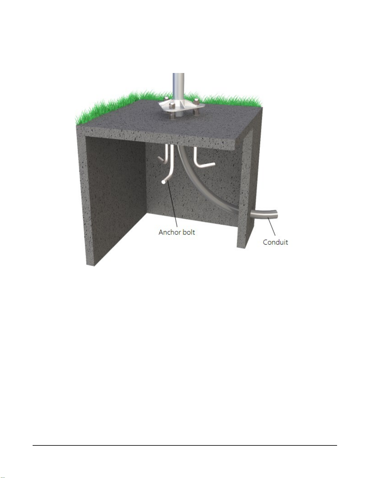
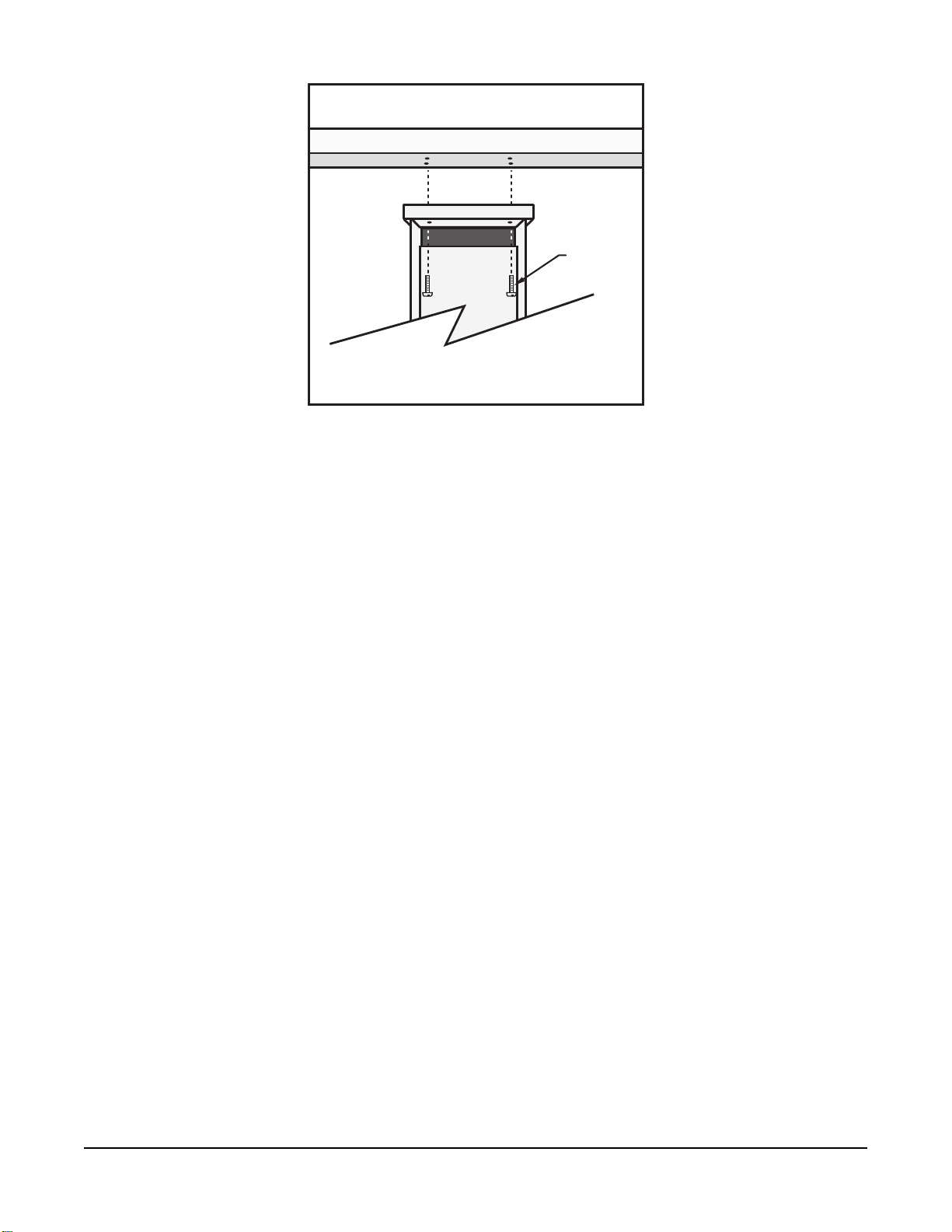
11. Put 2-by-4 spacers between the template and the top of the form. The bottom of the bolt
threads should be about 1 cm (0.5 in) above the concrete (FIGURE 6-2 (p. 14)). The
template must be level in two dimensions.
FIGURE 6-2. Cut-away view shows anchor bolt and conduit placement in cement pad
12. Use a trowel and edger to finish.
13. Wait 24 hours before removing the concrete form.
14. Wait seven days before mounting the pole.
6.2 Pole installation
The following components included with the T107 are used for this installation procedure:
(1) top pole section (tapered)
(1) base pole section
(6) 5/8-inch washers
(1) 4 m (12 ft), 10 AWG green copper stranded wire
Section6. Installation 14
Page 22
(1) white pole cap
(1) 6 m (20 ft) communications cable (phone or short haul modem)
(1) 6 m (20 ft) power cable (for AC option only)
(1) 6 x 19 mm (1/4 x 3/4 in) hex head self-drilling screw
The pole provides a support structure for mounting the T107 weather station components. The
pole is designed to withstand winds of 45 m/s (100 mph). The lightning rod assembly is attached
after the instrumentation enclosure is installed.
Use the following procedure to attach the pole to the base (FIGURE 6-3 (p. 15)).
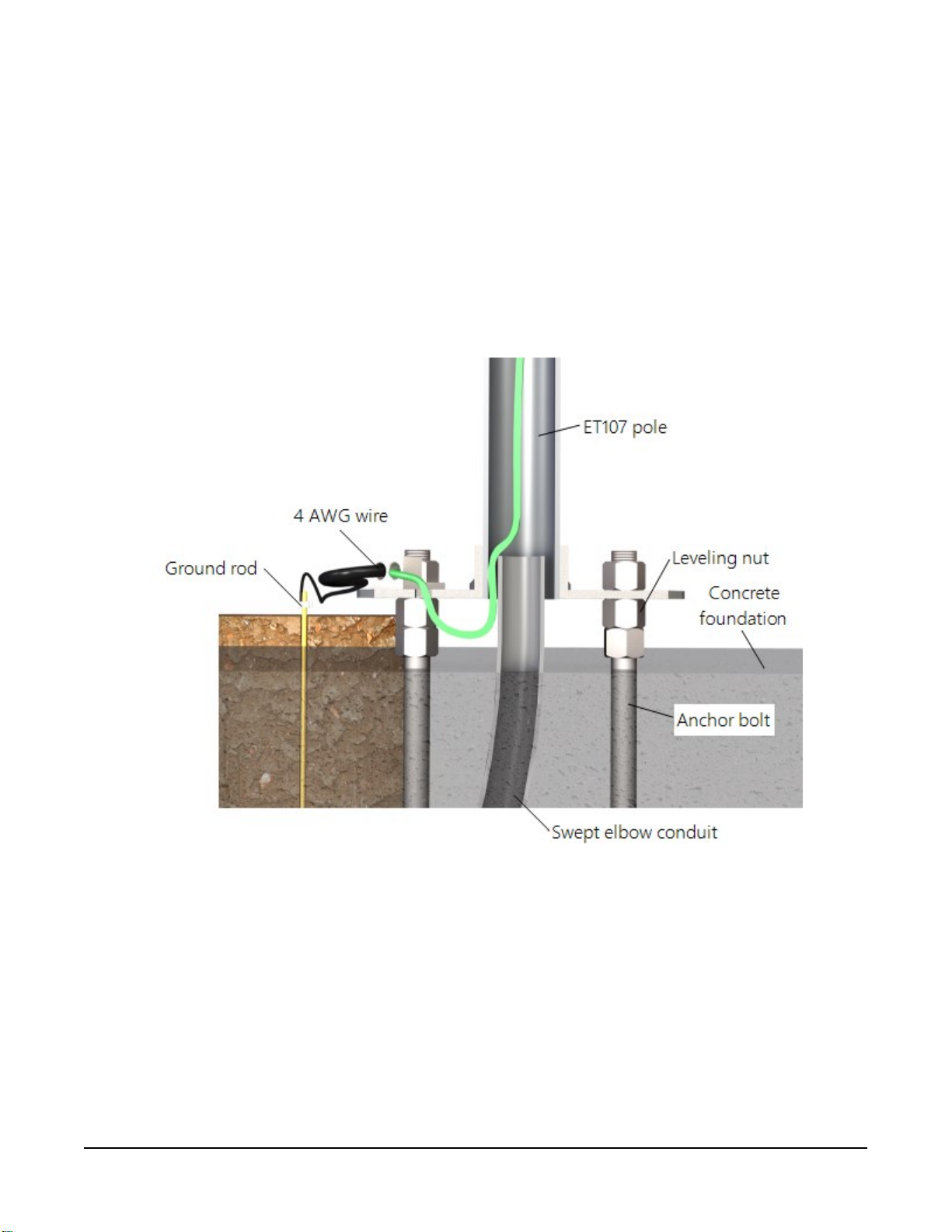
FIGURE 6-3. Transparent view shows raising and grounding the T107 pole
1. Dig a hole close to the concrete base to access the lower conduit opening.
2. From the hole, trench to the power and communications sources.
3. Remove the duct tape from both ends of the conduit.
4. Remove the template.
Section6. Installation 15
Page 23

5. Follow the ET Station Pole Assembly Instructions
(https://s.campbellsci.com/documents/us/manuals/et-station-pole-assembly-guide.pdf )
to secure the top and base pole sections by using the self-drilling screw provided with the
pole assembly.
6. Cut and save a 23 cm (9 in) piece of 10 AWG ground wire, which will be used to attach the
enclosure ground to the lightning rod assembly.
7. Thread the communications cable, power cable with connector ends of cable out the top of
pole, and grounding wire through the pole and conduit. Electrical fish tape will help. Leave
approximately 1 m (2 ft) of the supplied power and communications cable hanging out of
the top of the pole. Secure all wiring so it doesn’t slip back down through the pole.
NOTE:
Solar panel and radio frequency (RF) options will not have power or communications
cables.
8. Place the white pole cap over the pole end.
9. Raise the pole on a still day.
10. Place a washer on top of the two nuts on each foundation bolt.
11. Taking care not to damage cables between the pole and conduit, raise the pole and lower
it onto the conduit and mounting bolts.
12. Install a washer and nut on each bolt and hand tighten. Check plumb of the pole by
placing a level on the north and east sides of the lower pole section.
13. Adjust the topmost of the two lower nuts (levelling nut) on each bolt as necessary.
14. When plumb is established, lock the levelling nut in place by tightening the lowest nut
against it.
15. Tighten the three top nuts with the wrench.
6.2.1 Pole grounding
The following components included with the T107 are used for this installation procedure:
(1) 4 AWG ground wire
(1) 8 AWG ground wire
(1) copper ground lug, bolt
(1) ground rod, clamp
Use the following procedure to ground the pole (FIGURE 6-3 (p. 15) and FIGURE 6-4 (p. 17)).
Section6. Installation 16
Page 24
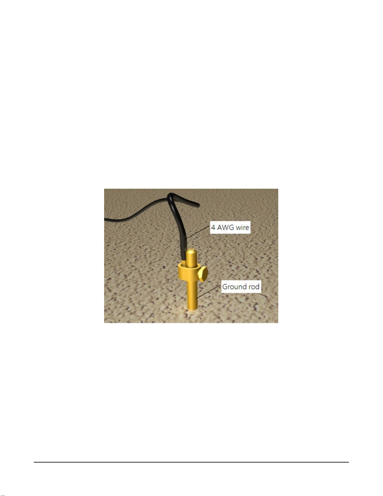
1. Place the ground rod clamp on the ground rod. Secure it about 8 cm (3 in) from the top.
Do this before the rod is driven into the ground. Be careful not to damage the clamp with
the hammer.
2. Taking care not to damage power or communications lines, drive the ground rod close to
the foundation using a fence post driver or sledge hammer. Drive the rod at an angle if an
impenetrable hardpan layer exists. Soften hard clay soils with water if necessary.
3. Strip 3 cm (1 in) of insulation from both ends of the 4 AWG ground cable.
4. Strip 3 cm (1 in) of insulation from the lower end of the 10AWG ground wire.
5. Loosen the set screw on the lug and insert the 4 AWG and 10 AWG wire.
6. Tighten the set screw (FIGURE 6-4 (p. 17)).
7. Loosen the ground rod clamp. Insert the 4 AWG wire. Tighten the clamp (FIGURE 6-4 (p.
17)).
FIGURE 6-4. Close-up of ground rod and 4 AWG cable
6.3 Enclosure installation
The weather station data logger, power supply, sensor connection panel, communications
devices, and data retrieval peripherals are mounted in the T107 enclosure.
Mount the enclosure on the pole as shown in FIGURE 6-5 (p. 18).
Section6. Installation 17
Page 25
1. Remove the front lid.
2. Remove the connector cover from the back of the enclosure by loosening the Phillips screw
at the bottom of the cover.
3. Loosen the mounting bracket bolts on the back of the enclosure wide enough to slide over
the pole. Slide the enclosure over the pole.
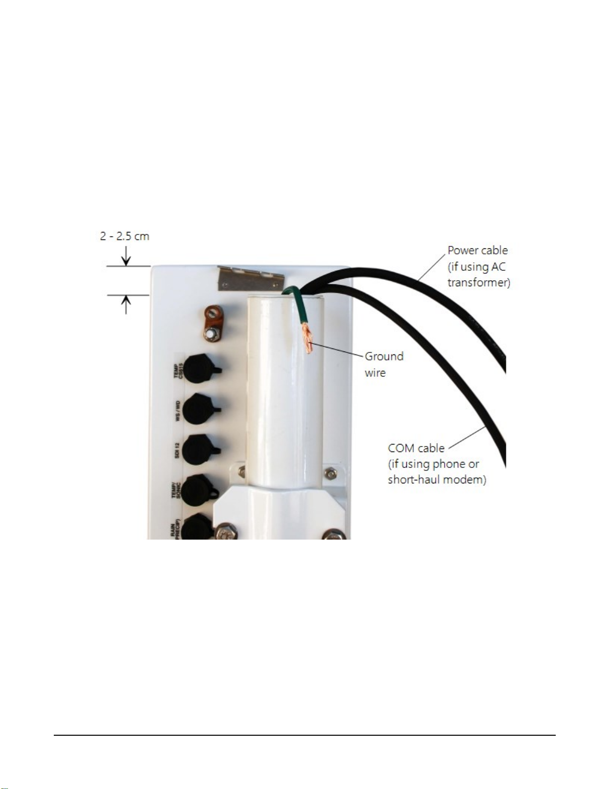
4. Position the enclosure so it faces east for northern latitudes or west for southern latitudes.
The top of the enclosure should be 2 to 2.5 cm (3/4 to 1 in) above the top of the pole
(FIGURE 6-5 (p. 18)).
FIGURE 6-5. Enclosure spacing above pole
6.4 AC power installation procedure
The AC power option includes a 100 to 240 VAC to 24 VDC power supply.
1. Mount the power supply inside a user-supplied junction box according to local electrical
codes.
Section6. Installation 18
Page 26

CAUTION:
Avoid dangerous electrical accidents when using the AC power option by locating the
transformer remotely and burying a low voltage line to the station. The low voltage will
carry up to 152m (500ft) on an 18 AWG power cable.
2. Shut off 110 VAC power at the main breaker.
3. Connect the primary leads of the power supply to the 100 to 240 VAC power source.
4. Connect a two-conductor cable to the secondary terminals of the power supply.
5. Route the cable from the power supply to the T107 enclosure according to local electrical
codes.
6. Splice the incoming two-conductor cable to the power cable provided with the station. Use
the direct burial splice kit when splices are in a valve box or buried.
CAUTION:
The splice and wire nut must be completely immersed into the silicone gel inside the
splice tube to be waterproof.
7. Connect the power plug to the POWER connector on the back of the enclosure (FIGURE 6-
6 (p. 20)). Ensure that the plug is completely seated on the connector and the locking ring
is turned a quarter revolution clockwise.
Section6. Installation 19
Page 27
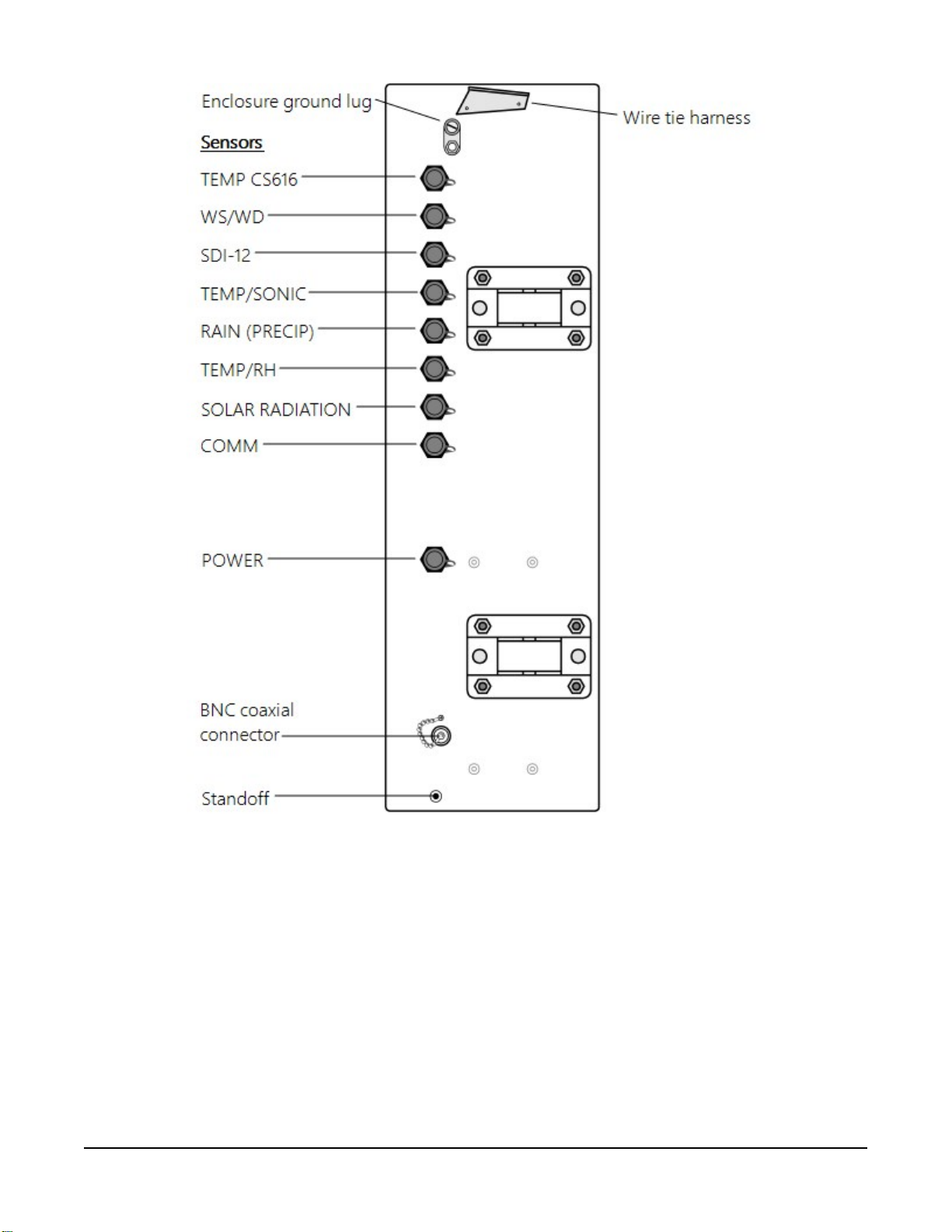
FIGURE 6-6. Position of bulkhead connectors
6.5 Crossarm installation procedure
The crossarm needs to be installed after the enclosure is mounted on the pole. You may need to
temporarily remove the communications option. Mount the crossarm as shown in FIGURE 6-7 (p.
21) without the wind sensor attached.
Section6. Installation 20
Page 28
Screws
(4)
FIGURE 6-7. T107 crossarm mounting
1. Adjust the bolts at the base of the pole to vertically level the top section of the mounting
pole.
2. Remove the front lid and the protective connector cover from the back of the enclosure by
loosening the one Phillips screw at the bottom of the cover.
3. Place the crossarm on top of the enclosure, lining up the four threaded holes on the
underside of the arm with the four holes in the top of the enclosure.
4. Attach the arm to the enclosure by inserting and tightening four Phillips head screws
(FIGURE 6-7 (p. 21)).
5. Adjust the position of the enclosure so that the crossarm is oriented along a due north to
due south axis with the rain gauge and solar radiation sensor (pyranometer) on the south
side for northern latitudes and the reverse for southern latitudes.
6.6 Sensor installation
The following components included with the T107 are used for this installation procedure:
(1) T107 crossarm with sensors (FIGURE 6-8 (p. 22))
(1) Met One 034B or WindSonic wind sensor
(1) White mounting shaft for 034B or WindSonic
(1) Radiation shield
Section6. Installation 21
Page 29
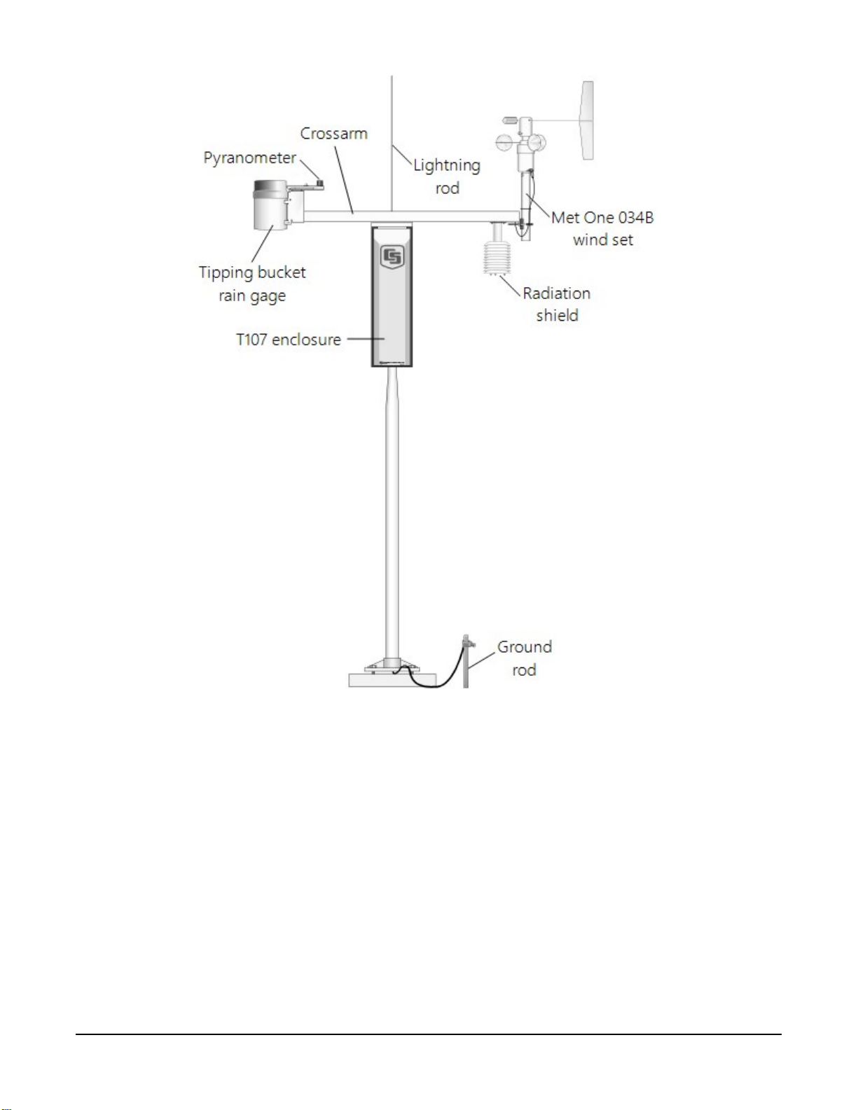
FIGURE 6-8. T107 instrumentation mounted on the T107 pole
6.6.1 RH and temperature radiation shield installation procedure
1. Remove the two knurled thumb screws taped underneath the crossarm.
2. Remove the yellow shipping cap from the end of the temperature/relative humidity sensor
(FIGURE 6-9 (p. 23) and FIGURE 6-10 (p. 23)).
Section6. Installation 22
Page 30
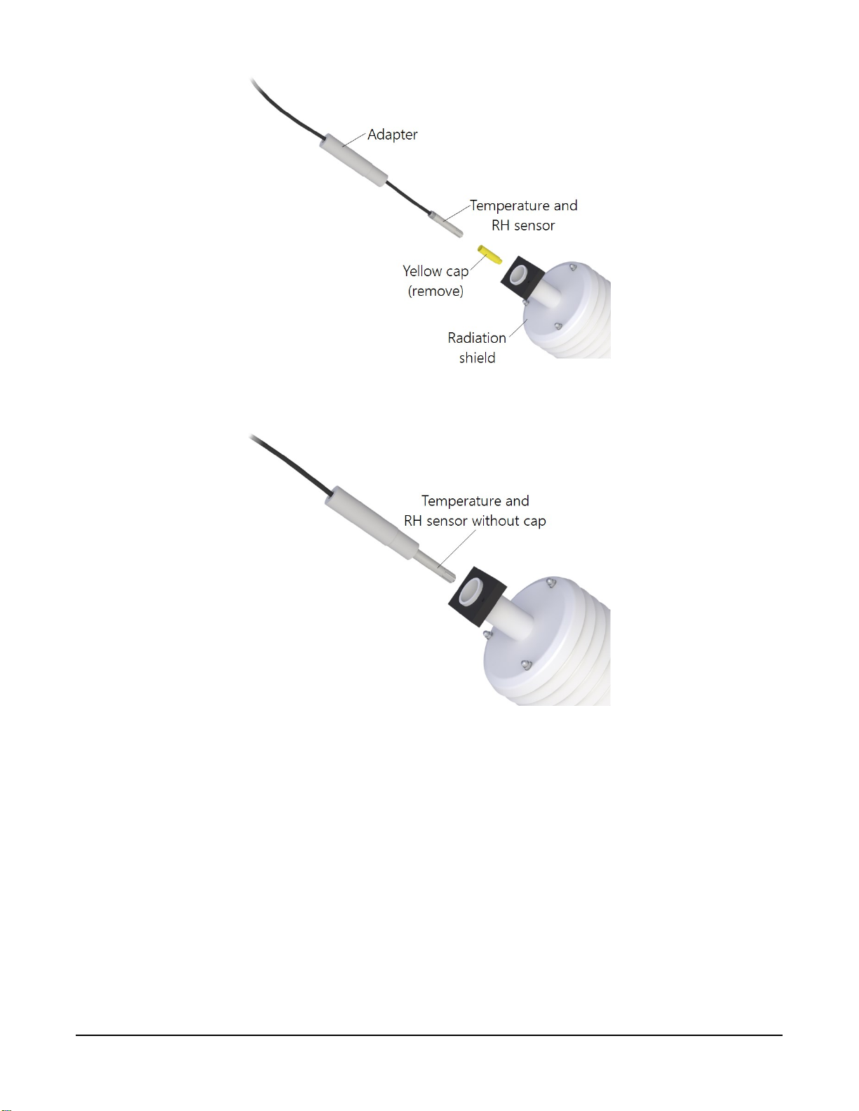
FIGURE 6-9. Temperature/relative humidity sensor with yellow protective cap
FIGURE 6-10. Temperature/relative humidity sensor without yellow protective cap
3. Insert the temperature/relative humidity into the radiation shield until it stops.
4. Attach the radiation shield to the underside of the crossarm using the two knurled thumb
screws from step 1.
5. Plug cable into the TEMP/RH connector on the enclosure. Ensure that the plug is
completely seated on the connector and the locking ring is turned a quarter revolution
clockwise.
Section6. Installation 23
Page 31

6.6.2 034B Wind Sensor (wind sensor option -MW)
Do the following to install the 034B Wind Sensor after the crossarm is securely installed (FIGURE
6-11 (p. 24)).
FIGURE 6-11. Wind and RH/temperature sensor installation
Section6. Installation 24
Page 32

FIGURE 6-12. 034B mounting to pipe
WARNING:
The wind vane can be easily damaged if dropped or bent. Leave the 034B wind vane in the
protective cardboard sleeve until it’s ready to be installed.
1. Remove the alignment screw at the base of the 034B-ET (FIGURE 6-12 (p. 25)).
2. Insert the 034B into the 034B Mounting Shaft.
3. Align the hole in the shaft with that in the 034B base and replace the screw. Do not
overtighten the alignment screw. Do not remove the shoulder screw at this time.
4. Insert the mounting shaft through the U-bolt on the crossarm.
5. Adjust the mounting shaft so that the cable and connector coming out the end of the
crossarm can plug easily into the mating connector on the 034B.
6. Lightly tighten up the U-bolt clamp nuts (FIGURE 6-11 (p. 24)).
7. Align the arrow on the alignment sticker with True South (Determining True North and
wind sensor orientation (p. 76)). The counterweight should also point due south.
8. Make sure the sensor cable is not being pinched by the U-bolt and tighten the U-bolt to
hold the sensor firmly.
Section6. Installation 25
Page 33

9. Plug the cable into the mating connector on the sensor. Ensure that the plug is completely
seated on the connector and the locking ring is turned a quarter revolution clockwise.
10. Install the wind vane using the Allen wrench supplied with the vane. Wind vane should be
perpendicular to the crossarm.
11. Put the MetOne sticker over the wind vane Allen screw opening.
12. Remove and keep the shoulder screw. The shoulder screw will be needed for replacing
bearings and/or potentiometer. The wind vane and cups should turn freely.
13. Plug the cable into the WS/WD connector on the enclosure. Ensure that the plug is
completely seated on the connector and the locking ring is turned a quarter revolution
clockwise.
WARNING:
Plugging this sensor into the SDI-12 connector can damage this sensor, the main enclosure
connector board, or both.
6.6.3 WindSonic 2-D Ultrasonic Wind Sensor (wind sensor option -GW)
When the WindSonic1-ET is added to the T107, a jumper setting must be changed (Changing the
jumper (p. 26)).
NOTE:
Jumper is set at the factory if the WindSonic is ordered with the T107 station.
6.6.3.1 Changing the jumper
The procedure to change the jumper follows:
1. Remove the cover of the enclosure.
2. Disconnect the ribbon cable from the CS I/O port.
3. Use a Philips screwdriver to loosen the four screws (FIGURE 6-13 (p. 27)).
Section6. Installation 26
Page 34

FIGURE 6-13. Screws that secure the electronics cover
4. Remove the electronics cover to expose the printed circuit board (PCB) (FIGURE 6-14 (p.
27)).
FIGURE 6-14. Removal of the electronics cover
5. Move the jumper at the top of the PCB so that it is placed over the centre and right pins
(FIGURE 6-15 (p. 28)).
Section6. Installation 27
Page 35

FIGURE 6-15. Jumper set for WindSonic1
6. Replace electronics cover.
7. Tighten screws.
8. Reattach the ribbon cable to the CS I/O port.
9. Replace enclosure cover.
6.6.3.2 WindSonic attachment to crossarm
1. Remove the three Phillips screws from the end of the white mounting shaft.
2. Remove the protective cap covering the WindSonic sensor cable plug.
3. Loosen the U-bolt holding the mounting shaft to the crossarm. Pull the shaft up and out of
the U-bolt (FIGURE 6-16 (p. 29)).
Section6. Installation 28
Page 36

FIGURE 6-16. WindSonic mounting shaft
4. Slide the connector and cable up through the centre of the mounting shaft.
5. Plug the cable into the sensor. The connector has a key and needs to be pushed in then
rotated clockwise to lock it in place (FIGURE 6-17 (p. 30)).
Section6. Installation 29
Page 37

FIGURE 6-17. WindSonic connected to cable
6. Centre the WindSonic over the three threaded screw holes on the mounting shaft and
screw it in place using the three Phillips screws taken off the shaft in step 1.
7. Slide the shaft and sensor back through the U-bolt.
8. Align the sensor with north by pointing the small coloured dot on outer edge of the
bottom of the sensor so it faces true north (Determining True North and wind sensor
orientation (p. 76)).
9. Space the sensor about 25 cm (10 in) above the crossarm and tighten down the U-bolt.
10. Plug the cable into the Temp/Sonic connector on the enclosure. Ensure that the plug is
completely seated on the connector and the locking ring is turned a quarter revolution
clockwise.
6.6.4 Rain gauge
For accurate measurements, the rain gauge needs to be installed so it is horizontally level. A
bubble level on the bottom of the inside of the rain gauge shows how vertical the pole was
installed.
Section6. Installation 30
Page 38

1. Pull the gold funnel up and off of the top of the rain gauge.
2. Remove the rubber band holding the tipping mechanism in place (FIGURE 6-18 (p. 31)).
FIGURE 6-18. Remove rubber band from tipping mechanism
3. Adjust the bolts at the bottom of the pole as needed to get the bubble level centered.
4. Put the gold funnel back on the top of the rain gauge after levelling has been
completed.
5. Plug the cable in the RAIN/PRECIP connector on the enclosure. Ensure that the plug is
completely seated on the connector and the locking ring is turned a quarter revolution
clockwise.
6.6.5 Pyranometer
1. Adjust the three levelling screws until the bubble level indicates plumb (FIGURE 6-19
(p.
32)).
Section6. Installation 31
Page 39

FIGURE 6-19. Pyranometer levelling
2. Remove the red or green shipping cap from the pyranometer (FIGURE 6-20 (p. 32)).
FIGURE 6-20. Remove red or green pyranometer cap
Section6. Installation 32
Page 40

3. Plug the cable in the SOLAR RADIATION connector on the enclosure. Ensure that the plug
is completely seated on the connector and the locking ring is turned a quarter revolution
clockwise.
6.6.6 Sensor connections
Each sensor cable plug attaches to a unique bulkhead connector (FIGURE 6-6 (p. 20) and FIGURE
6-21 (p. 34)). The labelling of the sensor cables match the labeling on the back of the enclosure.
For more information, refer to Sensor schematics (p. 69).
CAUTION:
Each plug must be completely seated on to the connector and the locking ring turned a
quarter revolution clockwise. Failure to seat the plug completely could cause corrosion and
water damage to both the enclosure and the cable.
NOTE:
Notice how the sensor caps are slid between the connector and the one above in FIGURE 6-
21 (p. 34). This will keep the caps out of the way of the connector cover.
Section6. Installation 33
Page 41

FIGURE 6-21. Connecting sensor cabling to enclosure
6.6.7 Sensor verification and clock set
1. Send the weather station program to the station using Campbell Scientific software such as
VisualWeather, PC400, or LoggerNet.
a. The station can be accessed directly using a CR1000KD keypad display at the weather
station. Plug the keypad into the extra plug coming off the 9-pin CS I/O connector.
Section6. Installation 34
Page 42

b. A laptop can be used to connect directly to the RS-232 port at the station using a
standard 9-pin serial cable. Do NOT use a null modem cable.
2. Verify all sensors are functioning correctly.
3. Verify the weather station clock and set as necessary.
NOTE:
Use standard time in the station if calculating. Do not use daylight savings time.
6.7 Communications peripherals
Communications kits ordered with the enclosure are pre-mounted and pre-wired; no further
connections inside the enclosure are necessary. Follow the external installation procedures in
later sections to make the external connections.
If you received a telecommunications kit separate from the enclosure, follow the “Internal
Installation” procedures outlined in later sections. Schematics for the phone and short haul
modems are in Communications modems schematics (p. 74).
Default settings for the data logger in the T107 station:
l PakBus address 1
l RS-232 Port: Autobaud (300 to 115,200 bps)
l ME: Autobaud
l SDC7 or SDC8: 115,200 bps
6.7.1 Direct connect to T107 station
The T107 station does not require an interface device for direct RS-232 communications. The
inside of the enclosure has a RS-232 and CS I/O port available for communications (see FIGURE
6-22 (p. 36)). Most standard communications options use the CS I/O port leaving the RS-232 port
free for direct communications with a laptop or desktop computer using a standard RS-232 serial
cable. The data logger used in the T107 station can communicate with more than one device at a
time allowing troubleshooting to be done in the field with a laptop computer while remote
communications devices are accessing the station.
NOTE:
Use Device Configuration Utility and connect directly to the station to change the data logger
configuration. Device Configuration Utility is included with LoggerNet and can be obtained,
at no charge, from our website at www.campbellsci.com/downloads .
Section6. Installation 35
Page 43

FIGURE 6-22. Close-up of the terminals and 9-pin ports in the T107 (battery not shown)
6.7.2 Phone modem
Phone modems enable communications between the T107 enclosure and a Hayes compatible
modem at your computer over a dedicated phone line. Phone line surge protection is built into
the enclosure. By default, the COM220 phone modem is configured for SDC7.
Section6. Installation 36
Page 44

6.7.2.1 Internal installation of phone modem
NOTE:
If the phone modem was ordered with the T107, skip this section and go directly to External
installation of phone modem (p. 38).
For installation inside the T107 enclosure, the following components are provided in the phone
modem kit:
(1) COM220 phone modem
(1) 30 cm (12 in) RJ-11 patch cord
(1) Mounting bracket
(4) Screws
(1) 130 cm (12 in) 14 AWG ground wire
Use the following procedure to install the phone modem (FIGURE 6-23 (p. 37)).
FIGURE 6-23. Phone modem mounting and connections (battery not shown)
1. Attach the modem to the modem bracket with the two screws provided. Mount the modem
and bracket into the enclosure with the three screws on the mounting plate.
2. Connect the modem 9-pin port to the enclosure CS I/O port with the ribbon cable supplied
with the enclosure (FIGURE 6-22 (p. 36), FIGURE 6-23 (p. 37)).
Section6. Installation 37
Page 45

3. Connect the modem RJ-11 jack to the enclosure RJ-11 jack with the RJ-11 patch cord
(FIGURE 6-23 (p. 37)).
4. Connect the modem ground terminal block (GND) to the enclosure ground by using the 14
AWG ground wire.
6.7.2.2 External installation of phone modem
The following modem kit components are used to make the external connections:
(1) Direct Burial Splice Kit
(1) 6 m (20 ft) Telephone Patch Cord with Connector
1. Connect the 6 m (20 ft) patch cord to the COM connector on the external back panel,
under the protective cover. Ensure that the plug is completely seated.
2. Splice the Tip and Ring lines of the patch cord to the telephone service line. Use the direct
burial splice kit when splices are in a valve box or buried.
NOTE:
The splice and wire nut must be completely immersed into the silicone gel inside the splice
tube to be waterproof.
6.7.3 Short-haul modem
Short-haul modems enable communications between a data logger and computer over two
twisted pairs of wires. The maximum distance between modems is determined by baud rate and
wire gauge. At 9600 bps, the approximate maximum cable length is 10 km (6 miles) using 19
AWG cable. DCE / DTE switches on the modems are set to DCE.
CAUTION:
It's critical to use at least a two twisted-pair cable with a shield wire. Shield wire(s) and/or any
additional unused conductors must connect to an earth ground at one end or the other of
the cable run.
6.7.3.1 Internal installation of short haul modem
NOTE:
If the short haul modem was ordered with the T107, skip this section and go directly to
External installation of short haul modem (p. 40).
Section6. Installation 38
Page 46

For installing inside the T107 enclosure, the following components are provided in the short-haul
modem kit:
(1) SC932C 9-pin to RS-232 DCE interface
(1) RAD modem
(1) RAD/SC932C mounting bracket
(1) 130 cm (12 in) 4-wire patch cable
Use the following procedure to install the short-haul modems (FIGURE 6-24 (p. 39) and FIGURE
6-25 (p. 40)).
FIGURE 6-24. Short-haul modem mounting and connection (battery not shown)
1. Mount the RAD / SC932C mounting bracket into the enclosure with the three screws
provided.
2. Connect the RAD modem and SC932C.
3. Strap them into the mounting bracket under the Velcro strap.
Section6. Installation 39
Page 47

4. Connect the SC932C 9-pin port to the internal enclosure CS I/O port with the ribbon cable
supplied with the enclosure (FIGURE 6-24 (p. 39)).
5. Wire the RAD modem to the enclosure with the 30 cm (12 in) patch cable. Match wire
labels to wiring panel labels on both the enclosure and the RAD modem (+XMT to +XMT).
A small screwdriver is provided with the enclosure to access the RAD modem connections.
Use the screwdriver to press down on the lever arm.
WARNING:
Pressing too hard on the lever arm can break it!
6.7.3.2 External installation of short haul modem
FIGURE 6-25. Short-haul modem wiring diagram
Components of the short haul kit used for external connections at the T107 enclosure are:
(1) 6 m (20 ft) 4-wire patch cable
(2) Direct burial splice kits
(1) User-supplied 22 AWG, REA, PE-86 Filled Buried Wire (supplier: Anixter,
www.anixter.com/en_us.html, Anixter pn F-02P22BPN)
Section6. Installation 40
Page 48

Components of the short haul kit used for external connections at the computer are:
(1) RAD modem
(1) 1.5 m (5 ft) 4-wire patch cable
(1) 3 m (10 ft) 14 AWG ground wire
(1) Surge protector and case
(1) 9-25 pin RS-232 serial cable
Use the following procedure to install the short haul modems (FIGURE 6-25 (p. 40)).
1. Connect the 6 m (20 ft) patch cable to the COM connector on the back side of the
enclosure. Splice the patch cable to the user-supplied cable, using the direct burial splice
kits.
NOTE:
The splice and wire nut must be completely immersed into the silicone gel inside the
splice tube to be waterproof.
2. Mount the surge protector box to a flat surface within 1.5 m (5 ft) of the serial port on the
computer. Ground the centre terminal to an earth (or building) ground using the 14 AWG
wire.
3. Connect the 1.5 m (5 ft) patch cable from the surge box to the RAD Modem. Fasten the
cable to the strain relief tab with a cable tie. Use the 9-to-25 pin serial cable to connect the
modem to the serial port on the computer.
4. Route the user-supplied cable from the remote splice to the surge protector. Connect it
and the 1.5 m (5 ft) patch cable to the surge protector.
6.7.4 Radio
Radios enable wireless communications between a data logger and computer. Maximum range is
0.8 to 21 km (0.5 to 13 miles). This is determined by radio model, antennas used, line of site, and
interference. This section provides instructions for RF407, RF412, RF422, RF451 and most radios
offered by Campbell Scientific.
NOTE:
AC power is recommended when using radios with the station. A 10-watt solar panel can be
used but days without sunlight and winter months with little sunlight should be considered.
The T107 station comes with a 7 amp-hour battery that is NOT designed to handle deep
discharge. Discharging the battery below 11 VDC may require battery replacement. Below are
some examples of power calculations. Battery current consumption is based on discharging
Section6. Installation 41
Page 49

the 7 amp-hour battery to 80% capacity (5.6 amp-hours). Discharging the battery past this
value could result in damaging the battery.
6.7.4.1 Example radio configuration and power usage
Configuration of base radio at the computer:
l Multi-Point Master
l RS-232 @ 115,200 bps (Use 9600 bps baud rate for non Campbell Scientific software if
needed)
l Network ID: 1234
l Frequency Key: 5
l 1 Watt Output (Transmit Power: 10)
Weather station radio:
l Multi-Point Slave
l Communication with Data logger via CS I/O SDC7
l Network ID: 1234
l Frequency Key: 5
l 1 Watt Output (Transmit Power: 10)
l Low Power Mode: 2
See your spread spectrum radio manual for changing radio settings.
Power usage examples:
Polling the station once every 10 minutes and staying on line with the station for one minute
consumes approximately 1.276 amps over a 24-hour period. If the station were to lose power, it
could run for around 4.3 days (105 hours) before damaging the battery. A station with a 10-watt
panel would need at least three hours of sunlight every day to keep the battery charged.
Recommendation here would be to decrease the power output of the radios or add a PS24
power supply and enclosure with a 24 amp-hour battery below the main enclosure. See PS24 24
Ah power supply with 10 x 12 inch enclosure (p. 80) for mounting options and information on the
PS24.
Polling the station once an hour and staying on line with the station for one minute consumes
approximately 0.388 amps over a 24-hour period. If the station were to lose power, it could run
for around 14 days (346 hours) before damaging the battery. A station with a 10-watt panel
would need at least one hour of sunlight every day to keep the battery charged.
Section6. Installation 42
Page 50

6.7.4.2 Internal installation of the radio
NOTE:
If the T107 was ordered with a radio kit, skip this section and go directly to External
installation of the radio (p. 44).
The following components are provided in the radio kit for installation inside the T107 enclosure:
(1) spread spectrum radio
(1) internal antenna cable
(1) enclosure mounting bracket
The radio comes mounted to the enclosure bracket. Install the assembly as follows.
NOTE:
Power the station down by moving the PS150 power switch to the Off position before
installing any communications option. Remember to move the switch back to the On position
after installing the enclosure.
1. Mount the bracket and radio inside the enclosure using the three existing screws (FIGURE
6-26 (p. 43)).
2. Thread the smaller SMA connector end of the internal antenna cable underneath the
battery cables and screw it to the RF antenna connector on the radio.
3. Attach the other end of the cable to the BNC RF bulkhead connector in the lower right
corner of the enclosure. Make sure all connections are tight (FIGURE 6-26 (p. 43)).
FIGURE 6-26. Radio mounted in the T107 (battery not shown)
4. Connect the long 9-pin female end of the ribbon cable to the CS I/O port on the radio.
5. Screw the connector to the radio using the provided two screws (FIGURE 6-27 (p. 44)).
Section6. Installation 43
Page 51

FIGURE 6-27. Attach ribbon cable to radio CS I/O port
6.7.4.3 External installation of the radio
The antenna should have been ordered with the radio kit.
The following components are provided with the radio kit for antenna installation on the T107
pole:
(1) antenna cable, 150 cm (59 in)
(1) adjustable angle antenna mounting bracket
(1) 8-450 x 53 mm (5/16-18 x 2 1/4 in) stainless steel U-bolt
(1) CM230 saddle bracket
(4) silicon bronze 8-450 mm (5/16-18 in) nuts
(4) 8 mm (5/16 in) stainless steel washers
(4) 8 mm (5/16 in) stainless steel lock washers
(4) black UV-resistant wire ties
1. Remove the sensor cable cover off of the back of the enclosure by loosening the thumb
screw at the bottom of the cover and swinging the cover back and down. The top of the
cover has a tab that fits in to the rectangular hole on the back of the sensor crossarm.
2. Remove the cap off of the BNC bulkhead connector located on the lower left corner of the
enclosure back.
3. Attach the antenna cable to the BNC connector.
4. Gently bring the cable up alongside the pole and loosely wire tie it to the wire tie block at
the top of the enclosure (FIGURE 6-28 (p. 45)).
Section6. Installation 44
Page 52

FIGURE 6-28. Loosely wire tie antenna cable
5. Drape the antenna cable between the pole and the enclosure (FIGURE 6-29 (p. 45)).
FIGURE 6-29. Loosely drape antenna cable over back of enclosure
6. Use the 2.125 stainless steel U-bolt to attach the adjustable angle mounting bracket to the
pole. Depending on the size of the antenna, position the bracket directly below, or above,
the enclosure top mounting bracket. The top of an omnidirectional antenna should not be
higher than the top of the lightning rod.
a. Slide the U-bolt behind the pole and through the oval notches on the adjustable
angle mounting bracket (FIGURE 6-30 (p. 46)).
Section6. Installation 45
Page 53

FIGURE 6-30. Slide antenna bracket U-bolt around back of the pole
b. Put a flat washer, lock washer, and a silicon bronze nut, in that order, on the ends of
the U-bolt (FIGURE 6-31 (p. 46)).
c. Tighten the nuts finger tight to allow the angle bracket to rotate around the pole.
FIGURE 6-31. Antenna bracket mounted to pole
7. Mount the saddle bracket to the adjustable angle mount bracket by inserting the ends of
the bracket through the quarter circle notches (FIGURE 6-32 (p. 47)).
8. Put a flat washer, lock washer, and a silicon bronze nut, in that order, on the ends of the
saddle bracket. Do NOT tighten down the nuts at this time.
Section6. Installation 46
Page 54

FIGURE 6-32. Mount antenna saddle bracket
NOTE:
Only rotate enclosure if needed to allow aiming of the Yagi antenna to the base
antenna. Keep solar radiation sensor towards the south as much as possible. Rotate
wind sensor to realign as needed.
9. Use the following procedure to install the Yagi antenna for the radio. Installation of the
omnidirectional antenna is similar (FIGURE 6-35 (p. 49)).
NOTE:
Mounting hardware that comes in the box with the Yagi antenna will not be used.
a. Slide the back of the Yagi antenna into the saddle bracket.
b. If the Yagi antenna at the station is communicating with an omnidirectional antenna
at the base, align the tines on the Yagi antenna so they are vertical (FIGURE 6-33 (p.
48)). If two Yagi antennas are used at both ends of communications, align the tines
the same. If interference is a concern, align the tines on the two Yagi antennas
horizontally instead of vertically. This will put the signal out of phase with other
antennas that are aligned vertically.
c. Tighten the nuts on saddle bracket to hold the antenna firmly in place.
CAUTION:
Do NOT over tighten the nuts on the saddle bracket or damage to the antenna
may occur.
Section6. Installation 47
Page 55

FIGURE 6-33. Yagi antenna mounted to saddle bracket
d. Orient the Yagi antenna so it’s aimed at the base antenna. You may have to flip the
adjustable angle bracket over to get the antenna and saddle bracket to point correctly
in the vertical direction.
e. Adjust the antenna cable at the BNC connector so the cable cover fits over all the
sensor cables as well as the antenna cable. You may have to gently bend the antenna
cable to put a 90° bend by the BNC connector end of the cable. Take the cover off
when you’re done.
f. Use one of the black wire ties to strap the antenna cable to the bundle of sensor
cables.
g. Tighten up the wire ties holding the antenna cable to the wire tie mount at the top of
the enclosure.
h. Take one black wire tie and strap the antenna cable to the antenna (FIGURE 6-34 (p.
49)). Leave a little slack on the cable between the wire tie and the antenna connector
so as not to stress the connector/cable connection.
i. Make sure a loop of antenna cable is directly under the Yagi antenna. This will act as
a drip loop and allow moisture to run off the antenna and cable (FIGURE 6-34 (p.
49)).
Section6. Installation 48
Page 56

FIGURE 6-34. Wire tie antenna cable to Yagi antenna and to pole
j. Wire tie the antenna cable to the pole.
FIGURE 6-35. Wire tie locations for omnidirectional antenna installation
k. Clean up the wire ties and put the cable cover back on.
Section6. Installation 49
Page 57

6.7.4.4 Base radio installation
The base radio kit comes with the following items.
(1) RS-232 serial data cable
(1) wall adapter (100 to 240 VAC, 50 to 60 Hz input; 12 VDC, 800 mA output; 1.8 m (6 ft) cable)
(1) radio
(1) window mount antenna with 2 m (7 ft) of cable
The radio needs to be connected to an RS-232 serial port on the calling computer and powered
by the wall adapter. The antenna is designed to stick to a window facing the weather station
(FIGURE 6-36 (p. 50) and FIGURE 6-37 (p. 51)).
CAUTION:
To comply with the FCC RF exposure requirements, the radio may be used only with
approved antennas that have been tested with this radio and a minimum separation distance
of 8 inches (20 cm) must be maintained from the antenna to any nearby persons.
1. Attach the RSMA connector on the antenna to the radio.
2. Remove the strip covering the adhesive on the antenna and stick it vertically to a window.
3. Attach the serial cable from the calling computer’s serial port to the RS-232 port on the
spread spectrum radio.
4. Plug the wall adapter into a wall outlet and plug the barrel connector into the POWER
connector. You should see the lights on the radio come on.
FIGURE 6-36. Base Radio installation
Section6. Installation 50
Page 58

FIGURE 6-37. A base radio installed in an office
6.8 Lightning rod installation
Install lightning rod as shown in FIGURE 6-38 (p. 52) and FIGURE 6-39 (p. 52).
1. Carefully mount the lightning rod clamp to the top of the pole (FIGURE 6-38 (p. 52)).
Position the clamp so it won’t interfere with the connector cover.
Section6. Installation 51
Page 59

FIGURE 6-38. Lightning rod bracket installation
2. Strip 2.5 cm (1 in) from the top of the main green 10 AWG pole ground wire.
3. Insert the exposed wire into the empty clamp opening. Do not tighten the screw at this
time (FIGURE 6-39 (p. 52)).
FIGURE 6-39. Grounding to lightning rod clamp
Section6. Installation 52
Page 60
4. Strip 2.5 cm (1 in) from both ends of the 23 cm (9 in) piece of 10 AWG green ground wire.
5. Insert one end into the enclosure ground lug located at the top back of the enclosure.
6. Put the other end in the same clamp opening as the main grounding wire and tighten
down the screw (FIGURE 6-39 (p. 52)).
7. Insert the lightning rod into the empty clamp opening. The milled flat side of the lightning
rod should face the clamping screw.
8. Tighten the screw to hold the rod firmly in place.
6.9 Solar panel installation
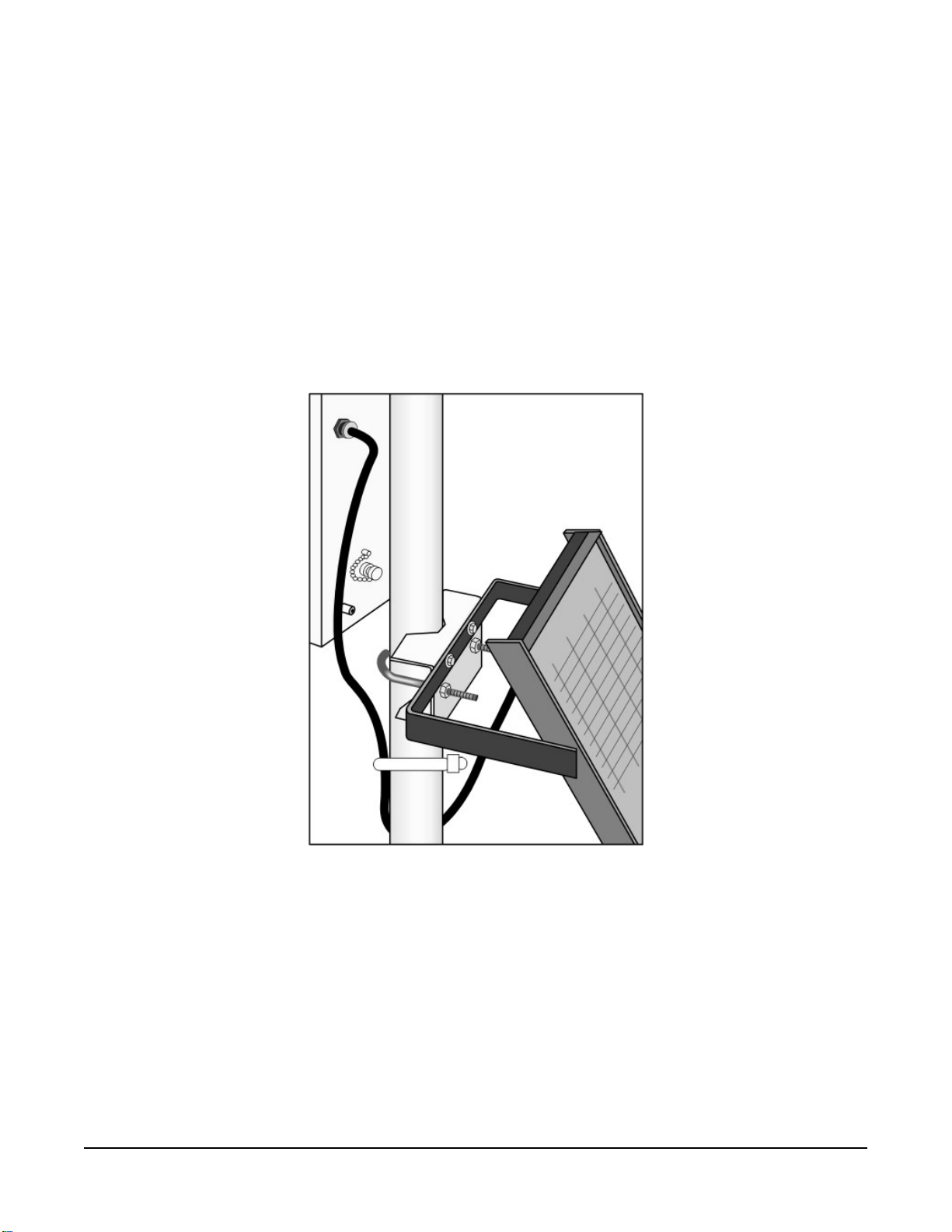
FIGURE 6-40. Solar panel mounting and cabling
1. Mount the solar panel to the pole using the mounting brackets (FIGURE 6-40 (p. 53)).
2. Mount the solar panel to the pole so it faces south (northern hemisphere). Position it as
high off the ground as practical, ensuring it cannot interfere with air flow or sunlight
around the sensors. The solar panel should be oriented to receive maximum insolation over
the course of the year. Suggested tilt angles referenced to the horizontal plane (FIGURE 6-
41 (p. 54)) are listed in Table 6-1 (p. 54).
Section6. Installation 53
Page 61

Table 6-1: Latitude and solar panel tilt angle
Latitude Tilt angle (α)
0 to 10 degrees 10 degrees
11 to 20 degrees Latitude + 5 degrees
21 to 45 degrees Latitude + 10 degrees
46 to 65 degrees Latitude + 15 degrees
>65 degrees 80 degrees
FIGURE 6-41. Side view of solar panel shows tilt angle
3. After determining the tilt angle, loosen the two bolts that attach the mounting bracket to
the panel.
4. Adjust the angle and tighten the bolts.
5. Secure the wire to the mast using wire ties (FIGURE 6-41 (p. 54)).
6. Connect the plug at the end of the solar panel cable to the Power connector. Make sure
the plug is fully seated and the locking ring turned clockwise until it stops.
Section6. Installation 54
Page 62

NOTE:
Schematics for the solar panel cable are in Power schematics (p. 73).
6.10 Battery installation
FIGURE 6-42. PS150 with lid open
1. Move the PS150 power switch to the OFF position (FIGURE 6-42 (p. 55)).
2. Remove the cover from the PS150 by sliding the latch up at one end of the cover and
sliding the cover down and out (FIGURE 6-42 (p. 55)).
3. Install the battery according to the diagram (FIGURE 6-42 (p. 55)).
4. Plug the battery wire into the connector.
5. Put the cover back on the PS150 and latch it in place.
NOTE:
Do not switch the power supply ON until AC or solar power has been connected to the back
of the enclosure.
Section6. Installation 55
Page 63

The green charge light on the PS150 will flash when charging voltage is present. The charge light
is not affected by the switch. Switching on the power supply without a charging voltage will run
the battery down.
FIGURE 6-43 (p. 56) shows factory wiring between the PS150 and the enclosure.
FIGURE 6-43. PS150 to T107 enclosure wiring
6.11 Restraining cables
1. Loosely wire tie power, communications, and grounding cable to the wire tie harness at the
top of the back of the station (FIGURE 6-44 (p. 57)). Do NOT clip back the wire tie at this
time.
Section6. Installation 56
Page 64

FIGURE 6-44. Cabling strapped to wire tie harness
2. Replace the connector cover. The tab at the top of the connector cover slides into the
opening on the back of the crossarm. Ensure that all cables and connector caps are under
the cover before tightening the Phillips screw at the bottom of the cover. Make sure that all
cables coming out of the top right of the connector cover are not being pinched.
Section6. Installation 57
Page 65

FIGURE 6-45. Connector cover in place
3. Tighten the wire ties holding the cables to the wire tie harness and clip off excess ties
(FIGURE 6-45 (p. 58)).
6.12 Sealing and desiccating the enclosure
The T107 enclosure is supplied with two desiccant packs. The desiccant maintains a low humidity
in the enclosure to minimize the chance of condensation on the instrumentation. Desiccant
should be changed when the internal enclosure humidity sensor measures 50% or higher. Install
the desiccant as shown in FIGURE 6-46 (p. 59). Keep unused desiccant tightly sealed in an
airtight container.
NOTE:
Place the desiccant into the enclosure after all other weather station installation steps have
been completed.
Section6. Installation 58
Page 66

1. Take the desiccant packs out of the plastic bag.
2. Strap the packs into the desiccant holder inside the lid of the enclosure using the two
Velcro straps.
3. Close the enclosure hasp securely. A padlock may be used on the latch for extra security.
FIGURE 6-46. Desiccant installation
6.13 T107 software
A variety of different software packages are available to work with the T107 station. This section
introduces software packages that can be used with the T107 station. It is not the goal to fully
explain capabilities of each package. All software packages mentioned below come with
extensive help files. Contact Campbell Scientific with questions and support. All software
includes installation instructions.
For Toro T.Weather 3.0 or higher, contact Toro NSN for support at (800) 275-8676.
Section6. Installation 59
Page 67

NOTE:
At default settings, the Campbell Scientific software packages will not work alongside of Toro
T.Weather. Contact Campbell Scientific for more information.
Free software packages include Short Cut for programming the station and PC400 which is used
to communicate with a direct connect or short-haul modem station and collect data. Both
packages can be downloaded from the Campbell Scientific website
www.campbellsci.com/downloads .
VisualWeather version 3.0 or higher is designed to work with the T107 station and can be used to
create programs, monitor present conditions, collect data, and create reports and graphs.
VisualWeather is a user-friendly program, requiring no data logger experience to use it.
VisualWeather supports direct connect, short-haul modem, radio, Ethernet, cellular with static IP
address, or phone modem communications. Refer to www.campbellsci.com/order/visualweather for
pricing.
LoggerNet is a powerful versatile package that requires some experience with data logger
programming. LoggerNet is used to create custom programming for the station as well as
handling large networks of stations. LoggerNet is not as easy to use as VisualWeather. Refer to
www.campbellsci.com/order/loggernet for pricing.
Section6. Installation 60
Page 68

7. Maintenance and troubleshooting
NOTE:
Contact your local TORO distributor for factory repairs and recalibrations.
7.1 Maintenance
Proper maintenance of the T107 components is essential to obtain accurate data. Equipment
must be in good operating condition, which requires a program of regular inspection and
maintenance. Routine and simple maintenance can be accomplished by the person in charge of
the weather station. More difficult maintenance such as sensor calibration, sensor performance
testing, and sensor component replacement, generally requires a skilled technician, or that the
instrument be sent to the manufacturer. Contact your local TORO distributor for more
information.
A station log should be maintained for each weather station that includes serial numbers, dates
that the site was visited, and maintenance that was performed.
7.1.1 Pole maintenance
Periodically check the pole for structural damage, proper alignment, and for level/plumb.
7.1.2 Power supply maintenance
Rechargeable power supplies should be connected to an AC transformer or unregulated solar
panel at all times. The PS150 green charge light will flash when voltage to the charging circuitry is
present. The charge indicating light runs independent of the power switch. Be aware of battery
voltage that consistently decreases over time, which indicates a failure in the charging circuitry.
Toro T.Weather software displays the battery voltage.
Occasionally clean the glass on the solar panel to improve its efficiency. Use warm mildly soapy
water and a clean cloth. Rinse with clean water.
7.1.3 Desiccant
Humidity is monitored inside the T107 enclosure using the Elan HM2000 RH sensor that is
incorporated in the enclosure. Change the desiccant packs when the enclosure RH exceeds 50%.
Section7. Maintenance and troubleshooting 61
Page 69

The enclosure RH sensor should be changed approximately every five years. The enclosure RH is
displayed in Toro T.Weather software.
Desiccant packs may be ordered in quantity of 20 individually sealed packs at a time or by the
individual pack.
7.1.4 Sensor maintenance
Perform sensor maintenance at regular intervals, depending on the desired accuracy and the
conditions of use. A suggested maintenance schedule is outlined below. T107 maintenance log
(p. 92) provides an example of a maintenance log file for one year of station use.
1 week
l Check the rain gauge screen and funnel for debris and level.
1 month
l Check the solar radiation sensor (pyranometer) for level and contamination. Gently clean
with blast of dry air, soft camel hair brush, or clean water if needed.
CAUTION:
Handle the pyranometer carefully when cleaning. Be careful not to scratch the surface
of the sensor.
l Do a visual/audio inspection of the 034B-ET anemometer at low wind speeds. Worn
bearings can cause the wind cups to spin in an uneven manner and/or make a grinding
sound.
l Check the WindSonic1-ET for contamination. If needed, gently clean the WindSonic1 with
a cloth and mild detergent.
CAUTION:
When cleaning the WindSonic1, do not use solvents and avoid scratching the sensor.
3 months
l Clean the radiation shield by removing the two knurled thumb screws holding it to the
crossarm. Gently pull the sensor out of the shield. Clean the radiation shield using warm
mildly soapy water. Rinse with clean water and allow the shield to dry before putting it
back on the crossarm.
l If necessary, clean the white filter element on the end of the temp/RH sensor. To clean the
filter, unscrew it from the end of the sensor and put it in a cup of CLEAN DISTILLED
Section7. Maintenance and troubleshooting 62
Page 70

WATER. Use no soap. Agitate the filter in the cup of water. Remove the filter and allow to
air dry before putting it back on the end of the sensor.
6 months
l Replace the anemometer bearings and reed switch on the 034B-ET if operating under
harsh conditions, such as constant high winds, blowing dust, and/or salt spray
contamination. Contact your local Toro distributor for service.
1 year
l Replace the wind speed (anemometer) bearings on the 034B-ET. Contact your local Toro
distributor for service.
l Replace reed switch the 034B-ET if needed. Contact your local Toro distributor for service.
l Check calibration of the HMP60-ETS Temp/RH sensor, which tends to drift up over time
giving readings higher than 100%. Replace RH chip if necessary (refer to FIGURE 7-1 (p. 64)
and Procedure for removing RH chip (p. 65)).
NOTE:
T107 stations began shipping January 2014 with an updated radiation shield with
knurled thumb screws, using the HMP60 ETS Temp/RH sensor. All information in this
document is also pertinent for the HMP50-ET, HMP60-ET, and HMP60 ETR sensors.
l Replace desiccant in enclosure housing as needed.
Section7. Maintenance and troubleshooting 63
Page 71

FIGURE 7-1. Exploded view of the temperature and RH sensor (adapter not shown)
2 years
l Replace vane potentiometer of the 034B-ET if needed (refer to
www.campbellsci.com/order/034b-et for part number and price). Contact your local
Toro distributor for service.
l Replace enclosure gasket if necessary. Contact your local Toro distributor for service.
3 years
l Send the solar radiation sensor (pyranometer) for calibration. Contact your local Toro
distributor for service. Sensor cannot be calibrated in the field. (Some users recommend
calibrating this sensor on a yearly basis.)
4 to 5 years
l Check sensor cables (as well as all other cables) for cracking, deterioration, proper routing,
and strain relief. Replace as required.
l Check enclosure relative humidity sensor. To check this sensor, take the lid off the
enclosure during routine desiccant replacement and leave it off for 5 to 10 minutes before
putting in new desiccant. While the lid is off the enclosure, compare the internal enclosure
humidity to the air humidity. Replace if > 10% off.
Section7. Maintenance and troubleshooting 64
Page 72

7.1.4.1 Procedure for removing RH chip
1. Unscrew the protective cap (see FIGURE 7-1 (p. 64)).
2. Hold the plastic sides of the RH chip and unplug it.
CAUTION:
To prevent scratching, avoid touching the silver chip, and handle the RH chip with care.
3. Rinse off the RH chip with distilled water or dispose of the old RH chip.
4. Hold the sides of the rinsed or new chip and plug it in.
5. Screw on the protective cap.
7.1.5 Data logger module
The data logger module contains a lithium battery that operates the clock and SRAM when the
module is not powered. The data logger does not draw power from the lithium battery while it is
powered by a 12 VDC supply. In an T107 stored at room temperature, the lithium battery should
last approximately 10 years (less at temperature extremes). Where the T107 is powered most or all
of the time, the lithium cell should last much longer.
While powered from an external source, the module measures the voltage of the lithium battery
daily. This voltage is displayed in the status table. A new battery will have approximately 3.6 volts.
The data logger Status Table has a “Lithium Battery” field. This field shows lithium battery
voltage.
Contact your local Toro distributor for replacing the battery when voltage is approximately 2.7 V.
If the lithium cell is removed or allowed to discharge below the safe level, the T107 will still
operate correctly while powered. Without the lithium battery, the clock will reset and data will be
lost when power is removed.
CAUTION:
Toro recommends factory replacement of the lithium battery. Misuse of the lithium battery in
the data logger or installing this lithium battery improperly can cause severe injury. It is a fire,
explosion, and severe burn hazard! Do not recharge, disassemble, heat above 100 °C (212 °F),
solder directly to the cell, incinerate, nor expose contents to water. Lithium batteries need to
be disposed of properly.
Table 7-1 (p. 66) lists the specifications of the battery.
Section7. Maintenance and troubleshooting 65
Page 73

Table 7-1: Data logger lithium battery specifications
Manufacturer Tadiran
Model TL-59025 (3.6 V)
Capacity 1.2 Ah
Self-discharge rate 1%/year @ 20 °C
Operating temperature range –55 to 85 °C
7.2 Troubleshooting
7.2.1 No response using the CR1000KD keypad 66
7.2.2 No response from data logger when using a communications peripheral 67
7.2.3 NAN, ±INF, or unreasonable results displayed in a variable or stored in a
data table 68
7.2.4 WindSonic1-ET diagnostic codes 68
7.2.1 No response using the CR1000KD keypad
Check keypad response after each of the following steps.
1. Make sure the battery has been installed and the PS150 power switch is set to ON (Battery
installation (p. 55)).
2. Use a voltmeter to measure the voltage on the 12V and G terminals (FIGURE 6-43 (p. 56));
the voltage must be from 9.6 to 16 VDC.
3. Use a voltmeter to measure the voltage on the 5V and G terminals (FIGURE 6-43 (p. 56));
the voltage must be from 4.9 to 5.1 VDC.
4. Disconnect the Temp/RH sensor from the back of the enclosure.
5. Disconnect the 9-pin ribbon cable from any communications option used with the station
so that only the keypad is attached to the 9-pin plug in the lower right corner of the
enclosure.
6. Cycle the power to the data logger by switching the PS150 power supply to OFF then to
ON, or by disconnecting and reconnecting the battery plug. The keypad should power up
and the Campbell Scientific logo and text should appear on the display.
7. Contact your local Toro distributor for service if still no response.
Section7. Maintenance and troubleshooting 66
Page 74

7.2.2 No response from data logger when using a communications peripheral
At the data logger:
1. Make sure the battery has been installed and the power switch set to ON (Battery
installation (p. 55)).
2. Use a voltmeter to measure the voltage on the 12V and G terminals (FIGURE 6-43 (p. 56));
the voltage must be between 9.6 and 16 VDC.
3. Use a voltmeter to measure the voltage on the 5V and G terminals (FIGURE 6-43 (p. 56));
the voltage must be between 4.9 and 5.1 VDC.
4. Make sure the data logger is connected to the communications peripheral, and the
communications peripheral is properly installed and configured (Communications
peripherals (p. 35)).
At the computer:
1. Make sure calling software is properly configured (PC400, VisualWeather, or LoggerNet).
2. Check the cable(s) between the serial port and the modem. If cables have not been
purchased through Toro, check for the following configuration using an ohm meter:
9-pin to 25-pin serial cable
Computer end Modem end
2 3
3 2
4 20
5 7
3. Make sure the communications device at the computer is properly configured and cabled
(Communications peripherals (p. 35)).
4. Call your local Toro distributor if still no response.
Section7. Maintenance and troubleshooting 67
Page 75

7.2.3 NAN, ±INF, or unreasonable results displayed in a variable or stored in a data table
1. Make sure the battery voltage is between 9.6 and 16 VDC.
2. Verify sensors are plugged into the correct sensor connector and the locking ring is
securely in place (see FIGURE 6-21 (p. 34)).
3. Check connectors for any corrosion on pins.
4. If Short Cut or VisualWeather is used to create the station program, double check the
wiring diagram to see if it matches the physical wiring on the sensor connectors on the
back of the enclosure.
5. If CRBasic is used to create the station program, verify channel assignments and multipliers.
Data logger program may need to be changed.
6. Inspect the sensor for damage and/or contamination. If damaged, contact your local Toro
distributor for repair or purchase of a replacement sensor.
7.2.4 WindSonic1-ET diagnostic codes
The WindSonic outputs a diagnostic code (Table 7-2 (p. 68)) with each wind direction and speed
measurement. A data logger program can be written that filters out all data when the diagnostic
is not 0. The programs can also report the number of good samples that were used in computing
the on-line statistics. If the total number of good samples is less than 98% of the expected
samples, the WindSonic may be in need of repair.
Table 7-2: WindSonic Diagnostic Codes
Diagnostic Status Comment
0 Okay All okay
1 Axis 1 Failed Insufficient samples, possible path obstruction
2 Axis 2 Failed Insufficient samples, possible path obstruction
4 Both Axis Failed Insufficient samples, possible path obstruction
8 NVM error Nonvolatile Memory checksum failed
9 ROM error Read Only Memory checksum failed
10 Maximum Gain Questionable wind measurements
Section7. Maintenance and troubleshooting 68
Page 76

8. Schematics of connectors
Knowledge of schematics is not necessary for routine installation and maintenance. However,
schematics may help with troubleshooting the T107. Each connector has a small molded dot by
pin 1. All of the schematics show the pinned connectors on the cables. Socketed connectors on
the back of the enclosure are the mirror images of what is shown.
8.1 Sensor schematics
FIGURE 8-1. Schematic of HMP60-ETS RH and Temperature Probe and connector
Temp/RH
Section8. Schematics of connectors 69
Page 77

FIGURE 8-2. Schematic of 034B-ET Wind Speed and Direction Probe and connector
WS/WD
Section8. Schematics of connectors 70
Page 78

FIGURE 8-3. Schematic of WindSonic1-ET Wind Sensor and connector Temp/Sonic
Section8. Schematics of connectors 71
Page 79

FIGURE 8-4. Schematic of CS305-ET Solar Radiation Sensor and connector Solar
Radiation
Section8. Schematics of connectors 72
Page 80

FIGURE 8-5. Schematic of TE525-ET Rain Sensor and connector Rain (Precip)
8.2 Power schematics
FIGURE 8-6. Schematic of solar panel and connector Power
Section8. Schematics of connectors 73
Page 81

8.3 Communications modems schematics
FIGURE 8-7. Schematic of short haul or phone modem and connector COMM
Section8. Schematics of connectors 74
Page 82

9. References
EPA, (1987). On-Site Meteorological Program Guidance for Regulatory Modeling Applications,
EPA-450/4-87-013. Office of Air Quality Planning and Standards, Research Triangle Park, North
Carolina 27711.
WMO, (1983). Guide to Meteorological Instruments and Methods of Observation. World
Meteorological Organization No. 8, 5th edition, Geneva, Switzerland.
The State Climatologist, (1985) Publication of the American Association of State Climatologists:
Height and Exposure Standards for Sensors on Automated Weather Stations, v. 9, No. 4 October,
1985.
EPA, (1989). Quality Assurance Handbook for Air Pollution Measurement Systems, EPA Office of
Research and Development, Research Triangle Park, North Carolina 27711.
Section9. References 75
Page 83

Appendix A. Wind Direction Sensor
Orientation
A.1 Determining True North and Sensor Orientation
Orientation of the wind direction sensor is done after the datalogger has been
programmed, and the location of True North has been determined. True North is
usually found by reading a magnetic compass and applying the correction for
magnetic declination; where magnetic declination is the number of degrees between
True North and Magnetic North. Magnetic declination for a specific site can be
obtained from a USGS map, local airport, or through a computer service offered by
the USGS at www.ngdc.noaa.gov/geomag. A general map showing magnetic
declination is shown in Figure A-1.
Declination angles east of True North are considered negative, and are subtracted
from 0 degrees to get True North as shown in Figure A-2. Declination angles west
of True North are considered positive, and are added to 0 degrees to get True North
as shown in Figure A-3. For example, the declination for Logan, Utah is 14 East.
True North is 360 - 14, or 346 as read on a compass.
Orientation is most easily done with two people, one to aim and adjust the
sensor, while the other observes the wind direction displayed by the datalogger.
1. Establish a reference point on the horizon for True North.
2. Sighting down the instrument centre line, aim the nose cone, or counterweight
at True North. Display the input location or variable for wind direction using a
hand-held keyboard display, PC, or palm.
3. Loosen the u-bolt on the CM220 or the set screws on the Nu-Rail that secure
the base of the sensor to the crossarm. While holding the vane position, slowly
rotate the sensor base until the datalogger indicates 0 degrees. Tighten the set
screws.
A-1
Page 84

Appendix A. Wind Direction Sensor Orientation
Figure A-1. Magnetic Declination at 2012.5 (degrees relative to true
north, positive is east)
Figure A-2. Declination Angles East of True North Are Subtracted From 0
to Get True North
A-2
Page 85

Appendix A. Wind Direction Sensor Orientation
Figure A-3. Declination Angles West of True North Are Added to 0 to Get
True North
A-3
Page 86

Appendix B. PS24 24 Ah power supply with 10 x 12 inch enclosure
The PS24 Power Supply is typically used when a solar-powered T107 transmits data using a
spread spectrum radio. However, the PS24 can be used for any situation where a larger capacity
battery is desirable.
B.1 PS24 components
The PS24 consists of a 24 Ah rechargeable battery in a 25 x 30 cm (10 x 12 in) environmental
enclosure (FIGURE B-1 (p. 81) through FIGURE B-3 (p. 82)). Typically, the PS24 is ordered without
a charging regulator and the PS100 or PS150 is moved from the station enclosure to the PS24
enclosure to serve as the charging regulator.
The battery should be recharged using AC power or solar power. An SP10 10-W solar panel, SP20
20-W solar panel, or wall charger is typically used to recharge the battery. The environmental
enclosure is mounted to the T107 pole using the mounting kit with hanger.
Appendix B. PS24 24 Ah power supply with 10 x 12 inch enclosure 80
Page 87

FIGURE B-1. PS24 enclosure with PS150 and battery bracket
FIGURE B-2. 24 Ah battery and battery cable
Appendix B. PS24 24 Ah power supply with 10 x 12 inch enclosure 81
Page 88

FIGURE B-3. Enclosure supply kit
B.2 PS24 installation
CAUTION:
The PS24 is purposely shipped without the battery mounted in its bracket. Do not install the
battery until instructed to do so.
1. Place the top enclosure bracket on the pole at approximately 10 m (3 ft) above the bottom
of the pole. The bracket should be installed with the hook side up, and facing north.
2. Slide the strut clamps into the bracket as shown in FIGURE B-4 (p. 83). Tighten the clamp
so that it doesn’t move.
CAUTION:
Do not over tighten the clamp!
Appendix B. PS24 24 Ah power supply with 10 x 12 inch enclosure 82
Page 89

FIGURE B-4. Strut clamps in brackets
3. Place the bottom strut clamp and bracket approximately 3 m (1 ft) below the top clamp.
This clamp is installed with the hook side down. The bracket might have to be moved a
little to accept the enclosure bracketing, so don’t tighten the bracket yet. FIGURE B-5 (p.
83) shows the top and bottom brackets correctly positioned on the T107 pole.
FIGURE B-5. Both strut clamps and brackets on T107 pole
4. Hook the enclosure on the top bracket as shown in FIGURE B-6 (p. 84).
Appendix B. PS24 24 Ah power supply with 10 x 12 inch enclosure 83
Page 90

FIGURE B-6. Top clamp hook side up
5. The bottom enclosure bracket should slide between the top lip of the bottom strut mount
bracket and the notch directly below. Move the bottom bracket if necessary, then bolt the
bottom bracket down (see FIGURE B-7 (p. 85)).
CAUTION:
Do NOT over tighten the bottom bracket.
Appendix B. PS24 24 Ah power supply with 10 x 12 inch enclosure 84
Page 91

FIGURE B-7. Enclosure mounted on T107 pole
6. The bottom enclosure bracket has a small metal locking mechanism. Push up on the small
Phillips screw underneath the mechanism and slide it to the left. Once in place, put a small
wire tie in the hole to the right of the locking mechanism (FIGURE B-8 (p. 86)).
NOTE:
To remove the enclosure from the bracketing, cut off the wire tie, slide the lock to the
right, and lift the entire enclosure off the bracketing.
Appendix B. PS24 24 Ah power supply with 10 x 12 inch enclosure 85
Page 92

FIGURE B-8. Enclosure locking mechanism
7. Install the solar panel above the PS24 enclosure, and face the solar panel south (FIGURE B-
9 (p. 87)).
Appendix B. PS24 24 Ah power supply with 10 x 12 inch enclosure 86
Page 93

FIGURE B-9. Fully mounted solar panel
8. Place a blanket or box over the solar panel to prevent any voltage output.
9. Route the solar panel cable and power cable coming from the main T107 enclosure into the
conduit at the bottom of the PS24 enclosure.
TIP:
Leave a loop of all cables under the PS24 enclosure to act as a drip line. Cut both
cables to whatever length you need. It doesn’t hurt to leave a loop of cable inside the
enclosure.
10. If this is a station retrofit, remove the PS100 or PS150 from the weather station enclosure
and install it into the PS24 enclosure. Unplug the 7 Ah battery from the PS100 or PS150 and
remove the battery from the battery compartment. The 7 Ah battery will not be used in the
configuration.
11. Wire the charging source (solar panel or AC source) into the two CHG terminals on the
CH150 or CHARGE terminals on the PS100 and PS150 (Table B-1 (p. 88)).
Appendix B. PS24 24 Ah power supply with 10 x 12 inch enclosure 87
Page 94

Table B-1: Solar panel or AC connections
Solar panel or AC wire colour Power supply connection terminal
Red CHG or CHARGE
Black CHG or CHARGE
NOTE:
Polarity makes no difference. Connect one wire per CHG terminal block.
12. If the charging source is a solar panel, remove the blanket or box from the solar panel once
it’s wired into the CH150, PS100 or PS150 regulator.
NOTE:
The charging LED (steady red on the PS100, or flashing green on the CH150 and PS150)
indicates that the charging source (solar panel or AC) is providing a charging voltage to
the battery. The battery will be charged regardless of the toggle switch position. The
switch on the regulator controls the voltage going to the terminal blocks marked +12V
on the PS100 and 12V on the CH150 and PS150.
Appendix B. PS24 24 Ah power supply with 10 x 12 inch enclosure 88
Page 95

FIGURE B-10. Procedure for installing and connecting battery
NOTE:
The power cable that carries the regulated 12 VDC power from the regulator in the
external enclosure to the T107 station enclosure has a two-pin connector on one end
and tinned wires on the other.
13. Toggle the power switch on the regulator (CH100, PS100, CH150, or PS150) to the OFF
position.
14. Wire the power cable to the regulator (Table B-2 (p. 90)).
Appendix B. PS24 24 Ah power supply with 10 x 12 inch enclosure 89
Page 96

Table B-2: Power cable-to-regulator connection
Wire colour Regulator connection terminal
Red 12V or +12V
Black G
15. Plug the two-pin connector into the POWER connector on the back of the station.
16. Plug the connector on the BP24 24 Ah battery wiring harness into the only battery
connector on the CH150 or PS150 (located adjacent to the charge ports) or into the Battery
– Internal connector on the PS100 or the INT connector on the CH100.
NOTE:
Since the power coming into the enclosure is regulated power coming from the
external enclosure, the wiring inside the T107 station enclosure needs to be different
than the standard wiring.
17. If this is a retrofit, inside of the ET station enclosure, wires come through the enclosure wall
from the POWER connector on the back of the station that used to be wired into the
charge ports of the PS100 or PS150. You have three options:
a. If you received a new POWER connector with your kit, remove the old POWER
connector by removing the plastic nut on the back of the station that holds the
POWER connector in place. Remove the old connector and replace it with the new
one, placing the foam washer inside the enclosure. Tighten the plastic nut. Plug the
plastic plug of the new POWER connector into the 12V port.
b. If you’re working with the original POWER connector, connect the black wire of the
POWER connector to the ground connector on the gray terminal strip, and the red
wire to the 12V connector on the terminal strip. The wire and plug previously used
with the PS100 or PS150 can be discarded
c. If you’re experienced with electrical work, butt splice the wires of the POWER
connector onto the wires from the harness assembly removed from the 7amp hour
battery (red to red and black to black). Plug the plastic plug into the 12V terminal.
18. An extra loop of ground wire was sent with the station. Use it to ground the enclosure to
the grounding rod system. The external ground lug is mounted on the bottom left corner
of the PS24 enclosure.
19. Move the switch to the ON position, and test the station.
Appendix B. PS24 24 Ah power supply with 10 x 12 inch enclosure 90
Page 97

20. After everything checks out, find the gray duct putty that was included in the enclosure
supply kit. Seal the cable-entry conduit by placing putty on the inside and outside of it.
Push the putty down into the cable entries.
CAUTION:
The enclosure needs to be sealed up tight, so don’t be stingy with the putty.
21. Put both bags of desiccant inside of the enclosure.
22. Stick the humidity indicator card on a wall inside of the enclosure.
CAUTION:
Pink on the humidity indicator card means it’s time to change the desiccant. Change
the desiccant at least every year. However, it’s often wise to change the desiccant every
six months.
23. Close the lids on the external enclosure and the T107 enclosure.
Appendix B. PS24 24 Ah power supply with 10 x 12 inch enclosure 91
Page 98

Appendix C. T107 maintenance log
Sensor installation date: _______________________________
Clean/inspect rain gauge sensor (recommended – weekly)
Date OK/comments Date OK/comments
Appendix C. T107 maintenance log 92
Page 99

Clean/inspect rain gauge sensor (recommended – weekly)
Date OK/comments Date OK/comments
Clean/inspect solar radiation sensor (recommended – monthly)
Date OK/comments
Appendix C. T107 maintenance log 93
Page 100

Clean/inspect temp/RH sensor and radiation shield (recommended – quarterly)
Date OK/comments
Replace wind speed bearings and reed switch (recommend – yearly)
Date OK/comments
Replace RH chip in the HMP60-ETS temp/RH sensor (recommended – yearly)
Date OK/comments
Replace desiccant bags (qty 2) inside enclosure (recommended – yearly)
Date OK/comments
Calibrate solar radiation sensor (CS305-ET) (recommended – every 3 years)
Date OK/comments
Appendix C. T107 maintenance log 94
 Loading...