

Page 1

ST350 Strain Transducer
2/08
Copyright © 2008
Campbell Scientific, Inc.
Page 2

Warranty and Assistance
The ST350 STRAIN TRANSDUCE R is wa rra nt ed by C AM PB ELL
SCIENTIFIC, INC. to be free from defects in materials and workmanship
under normal use and service for thirty-six (36) months from date of shipment
unless specified otherwise. Batteries have no warranty. CAMPBELL
SCIENTIFIC, INC.'s obligation under this warranty is limited to repairing or
replacing (at CAMPBELL SCIENTIFIC, INC.'s option) defective products.
The customer shall assume all costs of removing, reinstalling, and shipping
defective products to CAMPBELL SCIENTIFIC, INC. CAMPBELL
SCIENTIFIC, INC. will return such products by surface carrier prepaid. This
warranty shall not apply to any CAMPBELL SCIENTIFIC, INC. products
which have been subjected to modification, misuse, neglect, accidents of
nature, or shipping damage. This warranty is in lieu of all other warranties,
expressed or implied, including warranties of merchantability or fitness for a
particular purpose. CAMPBELL SCIENTIFIC, INC. is not liable for special,
indirect, incidental, or consequential damages.
Products may not be returned without prior authorization. The following
contact information is for US and International customers residing in countries
served by Campbell Scientific, Inc. directly. Affiliate companies handle
repairs for customers within their territories. Please visit
www.campbellsci.com to determine which Campbell Scientific company
serves your country. To obtain a Returned Materials Authorization (RMA),
contact CAMPBELL SCIENTIFIC, INC., phone (435) 753-2342. After an
applications engineer determines the nature of the problem, an RMA number
will be issued. Please write this number clearly on the outside of the shipping
container. CAMPBELL SCIENTIFIC's shipping address is:
CAMPBELL SCIENTIFIC, INC.
RMA#_____
815 West 1800 North
Logan, Utah 84321-1784
CAMPBELL SCIENTIFIC, INC. does not accept collect calls.
Page 3

ST350 Table of Contents
PDF viewers note: These page numbers refer to the printed version of this document. Use
the Adobe Acrobat® bookmarks tab for links to specific sections.
1. Introduction ...............................................................1-1
1.1 Typical Application.............................................................................. 1-1
2. Specifications............................................................2-1
3. Sensor Alignment and Installation..........................3-1
3.1 Alignment............................................................................................. 3-1
3.2 Installation............................................................................................ 3-2
3.3 Adjusting Excessive Transducer Offset................................................ 3-3
4. Wiring.........................................................................4-1
4.1 Initial Check-Out.................................................................................. 4-1
4.2 Excitation Voltage.................................................................................4-1
5. Mounting of Sensor to Various Surfaces................5-1
5.1 General.................................................................................................5-1
5.2 Mounting Information for Different Types of Surfaces.......................5-2
5.2.1 Steel............................................................................................ 5-2
5.2.2 Reinforced Concrete................................................................... 5-3
5.2.3 Pre-stressed Concrete..................................................................5-6
5.2.4 Timber ........................................................................................ 5-7
6. Calibration and Validation........................................6-1
7. Maintenance, Replacement Parts, and Repairs......7-1
7.1 Maintenance .......................................................................................... 7-1
7.2 Replacement Parts................................................................................ 7-2
8. Datalogger Programming.........................................8-1
8.1 CR1000 Example ................................................................................. 8-1
8.2 CR5000 Example ................................................................................. 8-2
Appendices
A. Special Instructions for using ST350.................... A-1
A.1 Instructions for Using ST350 Strain Transducer Extensions on
Reinforced Concrete Structures.............................................................. A-1
A.2 Attaching the Concrete Extension to a Strain Transducer.................. A-2
i
Page 4

ST350 Table of Contents
B. ST350 Accuracy Verification..................................B-1
C. Calibration Sheets...................................................C-1
Index.........................................................................Index-1
Figures
B.1 Verifying the Accuracy of ST350 Strain Transducers.........................B-1
B.1.1 Introduction ............................................................................... B-1
B.1.2 Background................................................................................ B-1
B.1.3 Factory Calibrations................................................................... B-1
B.1.4 Temperature Effects................................................................... B-2
B.1.5 Specimen Type and Size............................................................ B-2
B.1.6 Items for Consideration............................................................. B-2
B.1.7 Other Considerations................................................................. B-4
C.1 Example of Calibration Sheet — BDI Supplied.................................. C-1
C.2 Example of Calibration Sheet — CSI Supplied................................... C-2
3-1. Measurement Axis...............................................................................3-1
3-2. Surface Preparation - Location ............................................................3-2
3-3. ST350 Mounting Example ................................................................... 3-2
4-1. ST350 Electrical Wiring Diagram.......................................................4-1
7-1. ST350 Strain Transducer Test Output .................................................7-1
7-2. Proper Connection to Data Acquisition System for Tension and
Compression............................................................................................7-2
A-1. Extension Jig...................................................................................... A-3
A-2. Drawing Extension Jig.......................................................................A-3
A-3. Picture Compressing ST350 for Mounting Purposes ........................ A-4
A-4. Extension Alignment Tab..................................................................A-4
A-5. Desired Gage Length.........................................................................A-4
A-6. Example of Ceiling Mounting............................................................A-5
C-1. Bridge Diagnostics Calibration Sheet................................................C-1
C-2. Campbell Scientific’s Calibration Sheet............................................ C-2
Tables
A-1. Recommended Lower and Upper Gage Limits................................. A-1
A-2. Maximum Strain Ranges....................................................................A-2
ii
Page 5

Section 1. Introduction
This manual provides information for interfacing the ST350 Strain Transducer
to Campbell Scientific’s Dataloggers. Unless otherwise specified, all part
numbers are Campbell Scientific's.
This manual contains information on sensor specifications, operating
principles, installation, alignment, and calibration. The multiplier and offset
values given here are based on calibration data obtained from the Bridge
Diagnostic’s Calibration Sheet (see example Appendix C).
The most direct approach to quantifying live-load stresses in a structural
member is to record the induced strain. However, it can be tedious work
installing foil strain gages in the field since careful surface preparation and
soldering is often required. Now, most field strain gage installations can be
replaced with the highly accurate ST350 Strain Transducer. These units are
rugged and can be installed in any weather. Since they are pre-wired and easy
to mount, ST350 Strain Transducers will drastically reduce your field
installation time.
1.1 Typical Application
This transducer is typically used for dynamic or event driven stress in structural
members such as bridges or buildings. The ST350 Strain Transducers have
been designed for recording Live Load
there will be little to no temperature change during any short time-span testing
sequence.
When a transducer is attached to a structure, it is forced to have the same
deformation as the structure. However, if a temperature increase (or decrease)
occurs, and since the ends of the sensor are "anchored", the transducer will
expand between the end blocks and register compression. The same goes for a
drop in temperature which will register tension. If the sensor is to be mounted
on the structure for a long period of time, it will need to have its "zero" reset
periodically as it drifts around with temperature changes.
strains only. Hence it is assumed that
1-1
Page 6

Section 1. Introduction
1-2
Page 7

Section 2. Specifications
Effective gage
length:
Overall Size: 4.375 in x 1.25 in x 0.5 in (111 mm x 32 mm x 13 mm).
Cable Length: 10 ft (3 m) standard, any length available.
Material: Aluminum
Circuit:
Accuracy: ±2%, reading individually calibrated to NIST standards.
Strain Range:
Force req’d for
1000 με:
Sensitivity:
Weight: Approximately 3 oz. (85 g).
Environmental: Built-in protective cover, also water resistant.
3.0 in (76.2 mm). Extensions available for use on R/C
structures.
Full wheatstone bridge with four active 350 Ω foil
gages, 4-wire hookup.
Approximately ±2000 εμ.
Approximately 17 lbs. (76 N).
Approximately 500 εμ/mV/V.
Temperature
Range:
Cable: BDI RC-187: 22 gage, two individually-shielded pairs
Options: Fully waterproofed, Heavy-duty cable, Special quick-
Attachment
Methods:
-58°F to 185°F (-50°C to 85°C) operation range.
w/drain.
lock connector (available upon request).
C-clamps, threaded mounting tabs & quick-setting
adhesive, wood screws, or concrete anchors.
2-1
Page 8

Section 2. Specifications
2-2
Page 9
Section 3. Sensor Alignment and Installation
3.1 Alignment
The BDI ST350 will only measure strain in the axis in which it is aligned with,
therefore the more accurate the alignment, the more accurate the measurements
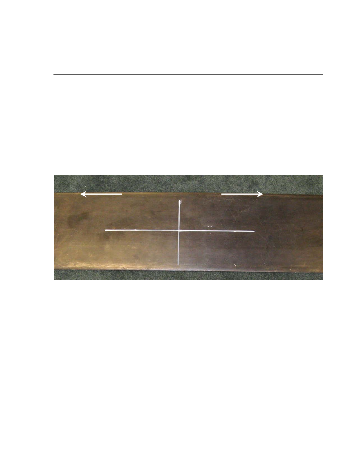
will be. The easiest way to align a transducer is to mark a “grid” type pattern
for both the proper foot placem e nt and measurement axis. First, locate the
center-line of the gaging area in both the longitudinal and transverse directions.
For example, if measurements are to be obtained at the mid-span of a joist,
locate the midpoint between the supports and the center-line of the joist. The
longitudinal mark should be about 8 inches long and the transverse mark about
4 inches long. This will allow the marks to be seen while the transducer is
being positioned. This can be seen in the picture below.
MEASUREMENT AXIS
FIGURE 3-1. Measurement Axis
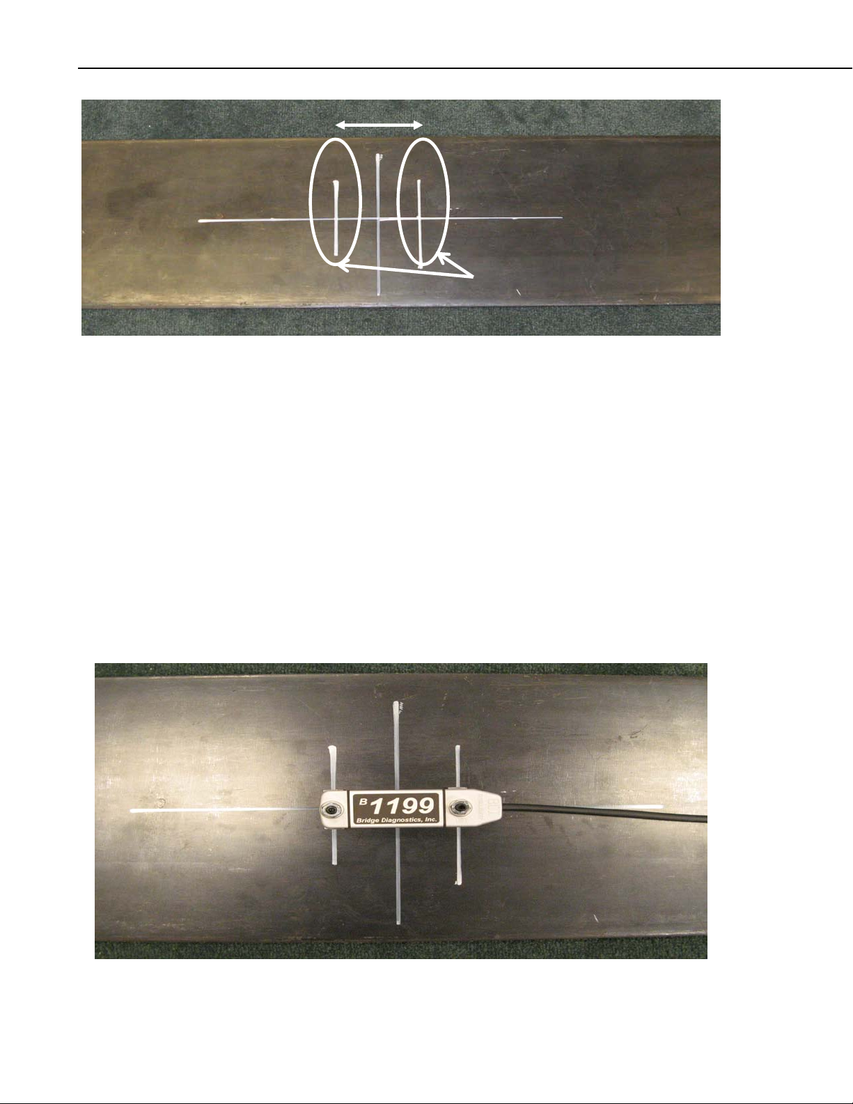
From the transverse mark, make two additional marks at 1.5 inches on either
side of the centering mark (see below photo). The areas circled below are the
portions of the cross-section that the necessary surface preparations must be
performed. Surface preparation techniques are explained in Section 5:
Mounting of sensor to various surfaces.
3-1
Page 10
Section 3. Sensor Alignment and Installation
FIGURE 3-2. Surface Preparation - Location
3.2 Installation
Once surface preparation is complete, the transducer can be installed using the
selected mounting technique (see Sections 5- Mounting of Sensors to Various
Surfaces). The two marks 1.5 inches from the center-line are used to locate the
transducer longitudinally; align these marks with the center of the transducer
feet. Notice that the front of the transducer (end opposite of the cable) as been
machined to a slight point. This poi nt , along with the cable exit on the rear of
the transducer, should be aligned with the measurement axis line to ensure that
strain is being measured parallel to the measurement axis. An installed
transducer can be seen in the picture below. Note that if an R/C extension is
used, the longitudinal mark will need to be 30 inches long in order to be seen
behind the transducer/ extension combination. It is important that this line is
drawn carefully as the strains are inherently more susceptible to error due to
misalignment as the gage length increases.
3”
SURFACE PREP. LOCATIONS
FIGURE 3-3. ST350 Mounting Example
3-2
Page 11

Section 3. Sensor Alignment and Installation
3.3 Adjusting Excessive Transducer Offset
If it is determined that zeroing cannot be accomplished with the Wheatstone
Bridge circuit, then it is possible that the transducer has either been damaged or
deformed slightly. In many cases the deformation is caused by a thermal
change in the gage due to weather changes, such as location of the sun. In this
case, the offset can be adjusted by simply loosening one nut and allowing it to
return to a “zero-stress” state. Once the nut is loose, rebalance the bridge and
ensure the gage can be zeroed. Retighten the nut and again, rebalance and
ensure the gage is zeroed. If the transducer still cannot be zeroed, ensure that
the mounting surface is flat. In many mounting situations, especially on timber
and aged concrete, additional surface preparation will need to be performed to
obtain a flat mounting surface. If it has been determined neither of the above
are causing the excessive offset proceed with the following steps:
1. Determine which direction the offset is in.
2. If the gage is too far in compression, loosen the free end of the gage (the
end opposite of where the cable exits).
NOTE
Sensor is in compliance if the offset is within ±2.1 mV/V
excitation (approximately 1000 microstrain).
3. Pull on this end of the transducer gently and re-tighten the nut or C-clamp.
4. If enough force cannot be applied with the gage attached to the structure,
remove the gage and pull it from both ends. Hopefully, while watching
the gage in “Monitor” mode, the gage will come closer to zero.
5. If the offset is in the opposite direction (i.e. too far offset in tension)
perform steps two through four, except push on the transducer rather than
pull.
If this initial offset cannot be removed, please return the transducer to BDI for
evaluation.
Remember! The transducers are high-quality, precision sensors and are
therefore quite sensitive, so be very careful while handling them!
3-3
Page 12

Section 3. Sensor Alignment and Installation
3-4
Page 13

Section 4. Wiring
4.1 Initial Check-Out
Upon receiving new transducers, it is important to check that they are in proper
working order. Using an ohmmeter, read the resistances between the black and
red wires and then the green and white wires, both read ings should be very
close to 350Ω. If they are not, the unit may be unusable and should be returned
to BDI either for repair or replacement. This test should be performed on a
periodic basis, especially if the transducer has been dropped or otherwise
mishandled.
Campbell Scientific, Inc. data acquisition systems support the use of a full
Wheatstone bridge sensor. The ST350 strain transducer has four active arms
consisting of 350 Ω strain gages. This configuration provides approximately 3
to 3-1/2 times the output of a standard 1/4-arm foil gage installation for a given
strain level. The connection sequence is shown in the following figure.
FIGURE 4-1. ST350 Electrical Wiring Diagram
NOTE
Output = V
Therefore, [+ Output
Compression]
is defined as ((+ Sig) – (- Sig))
diff
4.2 Excitation Voltage
The recommended excitation voltage is generally between 2.5 and 5 volts DC.
NOTE
When programming this transducer use Reverse Excitation to
cancel effects of Lead Resistance. CSI recommends performing
a reverse measurement to eliminate any hardware offsets. See
datalogger programming example for further information.
Once the transducer has been connected to the data acquisition system, the user
should verify output by monitoring the signal in real time while gently placing
the transducer in tension and compression by hand. This will ensure that
= Member in Tension] and [- Output = Member in
4-1
Page 14

Section 4. Wiring
tension provides a positive output signal and compression a negative signal. If
a tension force provides a negative signal (and vice-versa), the user should
either switch the signal leads or make appropriate adjustments to the signal
conditioning.
NOTE
Before going to the field, Campbell Scientific highly
recommends that a simple validation be performed by the user to
ensure that signal conditioning, gains, and calibration factors are
being properly applied.
Please see informational write-up entitled “Verifying the Accuracy of ST350
Strain Transducers – Appendix B” on some of the things to look out for while
running your own calibration verification.
4-2
Page 15

Section 5. Mounting of Sensor to Various Surfaces
5.1 General
In most situations, other than reinforced concrete, the most efficient method of
mounting a transducer is using the tab/glue method. This method is the least
invasive and is truly a “non-destructive testing” technique. Below is an outline
for implementing the glue/tab technique. Tips and alternative mounting
techniques for different mounting surfaces can be found in the following
sections.
1. Place two tabs in mounting jig (if available, if not simply hold with vice
grips). Place transducer over mounts and tighten the 1/4-20 nuts until
tight. Be sure that the transducer calibration number is facing up. This
procedure allows the tabs to be mounted without putting stress on the
transducer itself.
2. Mark the centerline of the transducer location on the structure. Place
marks 1-1/2 inch on both sides of the centerline and using a grinder,
remove paint or scale from these areas. For steel structures, a power
grinder is recommended for the initial cleaning. If available, use a
portable grinder (a Makita Model 9500D battery-powered grinder with a
46-grit wheel works very well) to “touch up” the newly-cleaned surface.
If attaching to concrete, lightly grind the surface with the portable grinder
to remove any scale and remove dust with a shop rag or paint brush.
3. Using the portable grinder, very lightly grind the bottom of the transducer
tabs to remove any oxidation and/or other contaminants. Before
mounting, set the transducer in the location it is to be attached, and ensure
that the tabs seat uniformly on the member and that the transducer doesn’t
“rock”. This is important for a good bond.
4. Apply a thin line of adhesive to the bottom of each transducer tab (Loctite
410 Black Toughened Adhesive, Part # 41045 in 0.7oz containers)
about 1/4” wide. If bonding to concrete, slightly more adhesive is
necessary to allow some to flow out and around the tabs. Mount the
transducer in the marked location, and then pull it away. This action will
apply adhesive to the structural member at the tab locations.
5. Spray each adhesive contact area on the structural member (just one “light
shot”) with the adhesive accelerator (Loctite Tak Pak 7452, Part # 18637
in 0.7oz aerosol spray container).
6. Very quickly, mount transducer in its proper location and apply a light
force to the top of the tabs (not the center of the transducer) for
approximately 15-20 seconds.
If the above steps are followed, it should be possible to mount each
transducer in approximately five minutes.
5-1
Page 16

Section 5. Mounting of Sensor to Various Surfaces
NOTE
For closest Loctite Distributor
Once testing is complete, carefully loosen the 1/4-20 nuts from the tabs and
remove transducer. If one is not careful, the tab will pop loose from the
structure (particu l arly when testing concrete structures) and th e transducer may
be damaged. Use vice grips to remove the tabs from the structure. If the tabs
remain with the transducer during removal, use vice grips to hold the bottom of
the tab while loosening the nut. DO NOT try to loosen the nut without keeping
the tab from twisting as the transducer can be damaged! The tabs can be reused by soaking them in acetone for 30-40 minutes to remove the hardened
adhesive. Be sure to cover the container since the acetone will evaporate
quickly and is very flammable!
call: 1 (800) 243-4874.
5.2 Mounting Information for Different Types of Surfaces
5.2.1 Steel
1. Examples:
Bridges, building components (columns, joists, floor systems, etc), large
mechanical equipment (tower cranes, mobile cranes, cooling towers, etc.),
liquid tanks, piles.
2. Methods for attaching the ST350 to steel:
a. Tab/Glue: See above.
b. C-clamps: Place transducer on specimen surface and tighten a
C-clamp over each raised bolt hole.
c. Th readed stud: Drill 1/4" holes in specimen at correct foot locations,
insert proper sized bolt, and tighten nut on each raised bolt hole.
3. Installation method for best measurements: All methods are sufficient.
4. Pitfalls to avoid during installation:
If the mounting surface is rough due to pitting or thick paint, smooth the
surface using acceptable methods.
If the mounting surface is not flat, a transducer can be installed in some
situations. Proceed with caution, ensuring not to distort the transducer as
damage may occur.
If the mounting surface is hot to the touch and/or the humidity level is
high, the glue may not stick as well as in other conditions. Although the
bonding strength is more than sufficient for taking measurements, when
loosening the nuts during the removal process, take extra care as the
mounting tab may pop off the member and the strain transducer can be
bent.
5-2
Page 17

5.2.2 Reinforced Concrete
Section 5. Mounting of Sensor to Various Surfaces
NOTE
See “Instructions for Using ST350 Strain Transducer
Extensions on Reinforced Concrete Structures” in Appendix A
for extension attachment instructions and important information
regarding the use of transducer extensions.
1. Examples:
Bridges, building components (columns, joists, floor systems, etc),
foundations, piles.
2. Methods for attaching the ST350 Strain Transducer to reinforced
concrete:
a. Tab/Glue: See above.
b. Tab/Glue + Threaded Stud (1/4"-20 x 3-1/4” Powers Fasteners Power-
Stud or similar)
- Locate the gauging point on the structure and make two marks
approximately 2 feet apart along the axis of where the
transducer/extension assembly is to be mounted. It can
sometimes be difficult to align the marks on the bottom of
concrete slab structures, particularly if the structure is skewed.
Often, a series of marks are laid out on the bottom of the slab and
a chalk line is used to lay out a grid, making gage alignment very
easy. Another alternative is to use a laser chalk line to
temporarily create a line while the gage is installed.
- Temporarily hold the transducer/extension assembly up to where
it is to be mounted to ensure that there are no obstructions along
the length of the unit. Make small marks at the two mounting
points, one for the transducer end and one for the selected gage
length on the extension end (6-24inches).
- Using a concrete drill, drill a 1/4” hole at the extension end mark
about 1.75” deep. For the tab end, it is possible that the concrete
surface will need to be smoothed slightly with a grinder to ensure
that the tab is making good contact with the structure. Once
smooth, use the edge of the grinder as a cutting wheel and cut two
or three grooves at a 45°
wipe all grinder dust clear from the location using a rag or paint
brush. If possible, use compressed air (available in cans) blow
the area clean.
- Place two to three washers on the stud and thread on a bolt about
1/2 of the way down its length. These washers will act as spacers
to account for the height of the tab on the transducer end. Slide a
3/8” deep wall socket over the stud and hold it against th e nut.
Drive the stud into the concrete by pounding on the end of the
socket; this will help prevent bending the stud.
angle to the direction of gage. Be sure to
5-3
Page 18

Section 5. Mounting of Sensor to Various Surfaces
- Tighten the washers against the concrete by twisting the nut with
an open-end wrench. It is important to set the stud before
attaching the extension to prevent damaging the gage. Once
secure, leave the nut on the bolt to hold the washers in place.
- Apply adhesive to the tab and push unit to mounting location.
Pull back tab, leaving a patch of adhesive on the structure.
- Apply accelerator to the adhesive, and quickly put assembly in
place. Hold the tab end of the unit in place by hand for several
seconds until the adhesive has hardened.
- While holding the transducer assembly in place, screw a nut on
the stud and tighten with an open-end wrench.
c. Threaded Studs Both Ends (1/4"-20 x 3-1/4” Powers Fasteners Power-
Stud or similar)
NOTE
When using this method it is very important that the drilling of
the holes is accurate to + 1/8” in order to align properly with the
transducer mounting holes. To help drill holes accurately, a steel
drilling guide made for the particular extension length can be
fabricated.
- Locate the gauging point on the structure and make two marks
approximately 2 feet apart along the axis of where the
transducer/extension assembly is to be mounted. It can
sometimes be difficult to align the marks on the bottom of
concrete slab structures, particularly if the structure is skewed.
Often, a series of lines are laid out on the bottom of the slab using
a chalk line, making gage alignment very easy. Another
alternative is to use a laser chalk line to temporarily create a line
while the gage is installed.
- Temporarily hold the transducer/extension assembly up to where
it is to be mounted to ensure that there are no obstructions along
the length of the unit. Make small marks at the two mounting
points, one for the transducer end and one for the selected gage
length on the extension end (6-24inches).
- Using a concrete drill, drill the first of two 1/4” hole about 1.75”
deep.
5-4
- Place two to three washers on the stud and thread on a bolt about
1/2 of the way down the stud. Slide a 3/8” deep wall socket over
the stud and hold it against the nut. Drive the stud into the
concrete by pounding on the end of the socket; this will help
prevent bending the stud.
- Tighten the washers against the concrete by twisting the nut with
an open end wrench. It is important to set the studs before
attaching the extension to prevent damaging the gage. Once
secure, leave the nut on the bolt to hold the washers in place.
Page 19

Section 5. Mounting of Sensor to Various Surfaces
- Slide the drilling jig over the stud and align it with the second
hole location.
- Drill the second 1/4” hole and follow the previous steps for
securing the second concrete anchor.
- Remove the washers and nut from this stud.
- Slide the transducer end over the stud without washers and the
extension end over the one with washers.
- While holding the transducer assembly in place, screw nuts on the
studs and tighten with an open-end wre nch .
3. Installation method for best measurements:
The method of gluing both tabs has been used for many years with very
few problems. The main concern is having a clean, dust free surface for
the glue to stick to. Occasionally the bottom of a slab may be wet or
excessively rough, or the sensors must stay in place for over a couple of
days, necessitating the use of mounting studs. Another consideration is if
the structure has automobile or other traffic below it, it is always a good
idea to use the studs on at least one end.
- Using two threaded studs is the most secure way to attach a
transducer to an R/C s t ructure, but it is considerably more timeconsuming and the accuracy of the marking and hole drilling is
significantly more important. If the area is difficult to access, the
transducers are going to be installed for an extended period of time,
or it is imperative that the measurements be taken at a specific time,
using two threaded studs is highly recommended.
- If the transducers are only going to be used for one day tab/glue is
likely sufficient. If the transducer is going to be installed for two to
four days the tab/glue + threaded stud is likely acceptable, but
depends on the climate and concrete condition. In areas of high
humidity the concrete tends to have higher moisture content. This
moisture builds up behind the glue tab and in some cases can cause
the tab to “pop” off.
4. Pitfalls to avoid during installation:
- If the Tab/Glue method is being used, ensure that the area is clean of
dust before installing the gage. A can of compressed air or an air
compressor is a great way to ensure a dust-free gluing area.
- If two threaded studs are going to be used, a drilling jig should be
fabricated to properly locate the hole positions. The transducer does
have an oval hole to help compensate for a hole being miss-drilled,
but as the gage length increases, the variability in the alignment
increases too.
- If the mounting surface is not flat or there are obstructions in the way
of the extension, the obstruction may have to be chipped/ground or
the mounting surface may need to be flattened with a grinder.
5-5
Page 20

Section 5. Mounting of Sensor to Various Surfaces
- When a transducer is attached to an extension it is significantly more
vulnerable to damage. A five gallon bucket is a good way to
transport multiple gages while extensions are installed. Put the
extension downward into the bucket and loop the cable over the
transducer to help prevent cable tangles.
5.2.3 Pre-stressed Concrete
1. Examples:
Bridges, building components (columns, joists, floor systems, etc),
foundations, piles.
2. Methods for attaching ST350:
a. Tab/ Glue: See above.
b. Threaded Studs: 1/4"-20 x 3-1/4” Powers Fasteners Power-Stud or
similar
- Locate the gaging point on the structure
- Using a concrete drill, drill 1/4” holes about 1.00” deep, ensure to
not drill into pre-stressing tendons.
- Place two to three washers on the studs and thread on a bolt about
half way down the stud. These washers will act as spacers to
account for the height of the tab on the transducer end. Slide a
3/8” deep wall socket over the stud and hold it against th e nut.
Pound in the stud by hitting the end of the socket; this will help
prevent bending the stud.
- Tighten the washers against the concrete by twisting the nut with
an open end wrench. It is important to set the studs before
attaching the extension to prevent damaging the gage. Once
secure, leave the nut on the bolt to hold the washers in place.
- Remove the washers and nut from the stud.
- Slide the transducer end over studs.
- While holding the transducer assembly in place, screw nuts on the
studs and tighten with an end wrench.
3. Installation method for best measurements:
Glue is sufficient for transducers that are only going to be installed for a
day or two. If the transducers are going to be left in place for an extended
period of time, threaded studs are required.
5-6
4. Pitfalls to avoid during installation:
- Know the locations of the pre-stressing strands. Locate the drilled
holes between the strands to prevent damage to the strand.
Page 21

5.2.4 Timber
Section 5. Mounting of Sensor to Various Surfaces
- If the Tab/Glue method is being used ensure that the area is clean of
dust before installing the gage. A can of compressed air or an air
compressor is a great way to ensure a dust-free gluing area.
1. Examples:
Bridges, building components (columns, joists, floor systems, etc), piles.
2. Methods for attached ST350:
a. Tab/ Glue: See above.
b. 2. Self-tapping Phillips-head screws:
- Washers are required to ensure that the head of the screw does not
sink into the transducer mounting hole.
- Use a power screwdriver to drive the screw until it is 1/16” from
the surface of the transducer then hand-tightened with a standard
Phillips screwdriver.
3. Installation method for best measurements:
Self-tapping screws
4. Pitfalls to avoid during installation:
- In many situations the timber members that the transducers are going
to be mounted to are twisted. This surface must be flattened using
appropriate techniques to reduce the chance of damage to the
transducer.
- If the wood has any sort of glue laminated section or chemically
treated, it is recommended that pilot holes be drilled.
5-7
Page 22

Section 5. Mounting of Sensor to Various Surfaces
5-8
Page 23

Section 6. Calibration and Validation
Calibration is performed on each sensor prior to shipping from the
Manufacturer and a Calibration Certificate is shipped with each sensor. This
certificate certifies that the sensor is traceable to NIST Standards. If this sensor
is out of specification it can be sent to Campbell Scientific, Inc. for recalibration.
NOTE
For quality control purposes, CSI recommends each transducer
be re-calibrated on an annual to bi-annual basis depending on the
usage and number of times the transducers have been installed on
a structure.
Based upon experience, the ST350 transducers should be re-calibrated after
every 15-25 installations depending on the care taken during the installation
process. The customer is responsible for any cost associated with the removal
of the transducer and shipping to CSI. If the part is under warranty, the
transducer will be re-calibrated at no further cost to the customer. If the part is
out of warranty, it will repair and calibrate according for a nominal fee.
6-1
Page 24

Section 6. Calibration and Validation
6-2
Page 25

Section 7. Maintenance, Replacement Parts, and Repairs
7.1 Maintenance
The ST350 Strain Transducer has been designed to minimize the amount of
maintenance required to keep the transducers operational. Before each use it is
recommended that every transducer be visually inspected for damage and
powered on to ensure it is working properly. This should be done two to three
weeks before the testing date in case any repairs are required.
Procedure for verifying ST350 is functioning properly
Ensure the Strain Transducer noise is within the specified noise range of the
Data Acquisition Equipment. This can be done by running a short test
(approximately 15-20 seconds) and allowing the sensors to collect data while
not being handled. An example of an output seen for this test can be seen
below in FIGURE 7-1.
FIGURE 7-1. ST350 Strain Transducer Test Output
1. Ensure the Strain Transducer returns a smooth output. Run a test at a
sample frequency higher than 30 Hz and apply a smooth tension force
(gently pulling one each end) followed by a smooth compression force
(gently pushing each end). The output returned should be a tension spike
followed by a compression spike and should not appear “stair-steppy”. An
example of this output can be seen below in FIGURE 7-2.
2. Using the data from #2, ensure the sensor returned to very near zero. In
some cases it may not return exactly to zero due to the sensor being heated
up from being handled and/or not being placed on the work surface in the
same position as it was sitting before being handled. If a significant offset
remains after such a test, this can be an indication of possible damage and
the unit should be sent back.
3.
Also, using the data from #2, ensure that the transducer has been
connected to the data acquisition system correctly by ensuring that tension
was registered as positive and compression as negative.
7-1
Page 26

Section 7. Maintenance, Replacement Parts, and Repairs
FIGURE 7-2. Proper Connection to Data Acquisition System for Tension and Compression
Debris and glue removal from foam areas between transducer body and
lid:
This area should be cleared of any debris or glue. The easiest way to remove
any sort of obstruction from the foam area is by using a dental pick. Glue can
be chipped away and debris, such as sand, can be pulled to the surface and
wiped away. Extra care should be taken when removing glue as it is easy to
slip and damage the gage or cut your hand.
NOTE
If the foam is damaged during the cleaning process, it cannot be
repaired or replaced!
Debris and glue removal from mounting feet:
This area should also be inspected and cleared of any debris and glue. To
remove glue from the feet, use the tip of a shop rag wetted with acetone. Wipe
the glue until it dissolves. A shop rag with mild soapy water can be used to
remove other debris from the mounting feet.
Mounting tab inspection:
These tabs have been design to be reusable by simply dissolving the glue with
acetone. Acetone can be reused multiple times, but if it becomes too saturated
with glue it will start leaving a thin layer of glue in the threads of the mounting
tabs. Also, sometimes when the mounting tabs are removed from a structure
the top threads can be chipped. If it becomes hard to thread nuts onto the
mounting tab stud, run a 1/4-20 tap down the threads to remove the chips and
glue from the threaded stud.
7-2
As stated in the previous sections, it is recommended each transducer be recalibrated on an annual to bi-annual basis or every 15-25 installations
depending on the care taken during the installation process.
7.2 Replacement Parts
In order to optimize the weather proofing of the transducer, it has been
designed to be completely sealed. Due to this design the only replacement part
available for the transducer is the cable. For the cable to be replaced, the
Page 27

Section 7. Maintenance, Replacement Parts, and Repairs
transducer must have at least a one foot cable exiting the transducer body. This
cable can be spliced to a new cable of the proper length.
If a transducer is damaged beyond repair, the transducer will be replaced at a
discounted price.
Please contact Campbell Scientific's Customer Service Department to obtain
authorization for return of the unit.
7-3
Page 28

Section 7. Maintenance, Replacement Parts, and Repairs
7-4
Page 29

Section 8. Datalogger Programming
This section is for users who write their own datalogger programs. A
datalogger program to measure this sensor can be created using Campbell
Scientific’s Short Cut Program Builder Software if using LoggerNet or by
using PC9000 software for the CR5000 or CR9000X. Short Cut or PC9000 are
used to create the datalogger program, the sensors should be wired to the
channels shown in the wiring diagram created by either program. Any
reference to specific channel assignments is for these examples only.
8.1 CR1000 Example
'CR1000
'Created by Short Cut (2.5)
'Declare Variables and Units
Public Batt_Volt
Public PTemp_C
Public Temp_C(2)
Public FullBR(2)
Units Batt_Volt=Volts
Units PTemp_C=Deg C
Units Temp_C=Deg C
Units FullBR=mV
'Define Data Tables
DataTable (MFGTRUSS,True,-1)
DataInterval (0,60,Min,10)
Sample (1,PTemp_C,FP2)
Sample (1,Temp_C(1),FP2)
FieldNames ("TrussTemp1")
Sample (1,FullBR(1),FP2)
FieldNames ("B1231")
Sample (1,FullBR(2),FP2)
FieldNames ("B1232")
EndTable
DataTable (Table2,True,-1)
DataInterval (0,1440,Min,10)
Minimum (1,Batt_Volt,FP2,False,False)
EndTable
'Main Program
BeginProg
Scan (1,Min,1,0)
'Default Datalogger Battery Voltage measurement Batt_Volt:
Battery (Batt_Volt)
'Wiring Panel Temperature measurement PTemp_C:
PanelTemp (PTemp_C,_60Hz)
'Type T (copper-constantan) Thermocouple measurements Temp_C(1):
TCDiff (Temp_C(1),2,mV2_5C,1,Type T ,P Temp_C,True,0,_60Hz,1,0)
'Generic Full Bridge measurements FullBR(1):
BrFull (FullBR(1),2,mV25,3,1,1,2500,False,True,0,_60Hz,1.0,0.0)
'Call Data Tables and Store Data
8-1
Page 30

Section 8. Datalogger Programming
CallTable (MFGTRUSS)
NextScan
EndProg
'***** Program End *****
8.2 CR5000 Example
'CR5000 Example using Strain Transducer from BDI ST350
'CR5000 Program created using PC9000 (5.3)
SequentialMode 'Forces program to as program is written
Public TEMP
Public BattVolt 'Battery voltage
Units BattVolt = Volts 'Battery voltage units
Dim I 'Declare I as a variable
Dim Count 'Declare Count as a variable
Dim TRef 'Declare Reference Temp variable
Public BLK(2), MBLK(2), OffsetVar(2), Flag(8), ZeroMode
Alias BLK(1) = ST350_1 'Assign alias name "B1231" to BLK(1)
Alias BLK(2) = ST350_2 'Assign alias name "B1232" to BLK(2)
Public loaded as Boolean
'\\\\\\\\\\\\\\\\\\\\\\\\ OUTPUT SECTION ////////////////////////
DataTable (MFGTRUSS,True,-1)
DataInterval (0,1,4,100) 'DataInterval( Tint oInt, Interv al, Uni ts, L apses)
Sample (1,TEMP,FP2) 'Sample( Reps, Source, DataType )
'Sampling Temperature by the gages
Sample (2,BLK(),IEEE4) 'Sample Transducers
Sample (1,BattVolt,FP2)
EndTable 'End of table MFGTRUSS
'--------------- Store zero va lues from Sub Zero8 ---------------
DataTable(CalTable,NewFieldCal,50)
SampleFieldCal 'Stores the zeroing values
EndTable
'\\\\\\\\\\\\\\\\\\\\\\\\\\\\ PROGRAM ////////////////////////////
BeginProg 'Program begins here MainSequence
MBLK(1) = 503.1 'Multiplier for Transducer Calibration and Calculations "ST350_1"
MBLK(2) = 508.1 'Multiplier for Transducer Calibration and Calculations "ST350_2"
Loaded = LoadFieldCal(0) 'Needed for FieldCal Instruction
Scan(100,mSec,10,0) 'Scan( Interval, Units, BufferOption, Count )
'Scan once every 100 milli-seconds
If Flag(8) = True Then
zeromode = 1
Flag(8) = False
EndIf
Battery (BattVolt 'Battery voltage measurement
PanelTemp (TRef,200) 'RefTemp,Integrate
'TCDiff( Dest, Reps, Range, DiffChan, TCType, TRef, RevDiff, SettlingTime, Integ, Mult, Offset )
TCDiff (TEMP,1,30,1,0,TRef,1,4000,250,1,0)
8-2
Page 31

Section 8. Datalogger Programming
'\\\\\\\\\\\\\\\\\\\\\\\\\\\\ Bridge Blocks //////////////////////////////
'BrFull(Dest,Reps,Range,DiffChan,ExChan,MeasPEx,ExmV,RevEx,RevDiff,SettlingTime,Integ,Mult,Offset)
BRFull (BLK(),2,4,2,VX1,2,5000,False,True,4000,16670,MBLK(),Of fsetVar())
'FieldCal (0,MeasureVar,1,Multiplier,OffSet,Mode,KnownVar,Index,3)
FieldCal (0,BLK(),2,MBLK(),OffsetVar(),ZeroMode,0,1,10) 'Field Cal determines zeroing
coefficients
CallTable CalTable
CallTable MFGTRUSS
Next Scan 'Loop up for the next scan
EndProg 'Program ends here
8-3
Page 32

Section 8. Datalogger Programming
8-4
Page 33

Appendix A. Special Instructions for using ST350
A.1 Instructions for Using ST350 Strain
Transducer Extensions on Reinforced
Concrete Structures
Special gage-lengthening extensions ha ve been designed for use with the
ST350 Strain Transducers in order to measure surface strains on reinforced
concrete (R/C) structures. The aluminum extensions simply increase the
transducer gage length to allow an “averaged” strain value to be recorded in the
presence of cracks associated with most R/C structures. These units make
available seven additional gage lengths, each one an integer multiple of the
original 3-inch (76.2mm) transducer gage length.
There are three items to consider when selecting an appropriate gage length for
a particular R/C member. The first is that it must be long enough to minimize
the effects of flexural cracks. There are several factors that control crack
formation in concrete, primarily the beam depth, steel ratio, concrete strength,
and bond strength. While there are no precise methods for determining a
minimum crack spacing, it has been determined experimentally that a gage
length equal to the member depth (d) is satisfactory for slabs and rectangular
beams and 1.5 times d is suitable for T-beams. The second item to consider is
that the gage length be short enough that the measured strains are not
significantly affected by moment gradients. An upper limit of 1/20
length (L) will usually maintain the gradient below 5%. In general, it is desired
to obtain as long a gage length as possible without exceeding the upper bound.
The following table provides the recommended lower and upper gage length
limits for R/C members.
th
the span
TABLE A-1. Recommended Lower and Upper Gage Limits
Member Type Lower Limit Upper Limit
Slabs and Rectangular Beams 1.0 x d L / 20
T-Beams 1.5 x d L / 20
The third item is the available strain range of the transducer. As the gage
length is progressively increased, the force on the transducer imposed by the
extension is increased as well for a given amount of strain. This has the effect
of reducing the available strain range for the transducer/extension assembly.
The upper limit of the strain range recommended for aluminum transducers is
approximately ±4000 με. However, to minimize the force in the system and to
avoid the mounting tabs from popping off the concrete members during
loading, BDI recommends keeping the maximum strain in the transducer to
about 1,000 με. Therefore, the following table has been developed to indicate
the maximum strain ranges for each available gage length. Higher strains can
of course be measured. However, special attention should be paid to the gain
settings on the data acquisition equipment being used. If the load is going to be
A-1
Page 34

Appendix A. Special Instructions for using ST350
very heavy, we recommend that the gain level for the STS be set to 500. It
should be noted that in most cases, the live-load strain magnitudes recorded by
BDI on reinforced concrete structures have been less than 100 με.
Stress for
= 4,000 psi
c
Approx. Conc.
f’’
Multiple of
Original
Length
1 3 in (76.2 mm)
2 6 in (152.4 mm)
3 9 in (228.6 mm)
4 12 in (304.8 mm)
5 15 in (381.0 mm)
6 18 in (457.2 mm)
7 21 in (533.4 mm)
8 24 in (609.6 mm)
Actual Gage
Length w/
Extension
TABLE A-2. Maximum Strain Ranges
Maximum
Strain
Range
±1000 με.
±500 με.
±330 με.
±250 με.
±200 με.
±160 με.
±140 με.
±125 με.
Approx. Conc.
Stress for
= 3,000 psi
f’’
c
3.1 ksi 3.6 ksi 4.0 ksi 30 ksi
1.6 ksi 1.8 ksi 2.0 ksi 15 ksi
1.0 ksi 1.2 ksi 1.3 ksi 9.9 ksi
780 psi 900 psi 1.0 ksi 7.5 ksi
625 psi 720 psi 800 psi 6.0 ksi
500 psi 575 psi 650 psi 4.8 ksi
440 psi 500 psi 560 psi 4.2 ksi
390 psi 450 psi 500 psi 3.8 ksi
Approx. Conc.
f’’
A.2 Attaching the Concrete Extension to a Strain
Transducer
Stress for
= 5,000 psi
c
Approx.
Steel
Re-bar
Stress
Once a gage length has been determined, there are three possible scenarios for
mounting the transducer/extension assemblies to the structure:
1. Adhesive/tabs on both ends. If conditions are dry, the concrete surfaces
relatively smooth, and testing will not last more than a day, the
tab/adhesive system will usually work fine as described below.
2. Adhesive/tab on transducer end and a masonry anchor on the extension
end. This is the preferred method of BDI. Again, if conditions are dry,
then the adhesive/tab system on one end will be sufficient for a couple of
day’s worth of testing, as long as the other end is securely mounted with a
mechanical anchor. It is highly recommended to use masonry screws such
as 1/4-20x3.25” concrete studs or another type of masonry anchor (readily
available at most hardware stores) to install transducer/extension assembly
due to the additional weight of the extension.
3. Anchor/masonry anchor on both ends. Use this approach only when the
structure is wet and/or very rough.
In either of the above scenarios, the steps below should be followed for
mounting the extensions to the transducers. The extension jig is used to
ensure that the transducer is aligned properly with the extension. If using
the anchor mounting on both ends, then omit the mounting tabs described
below.
A-2
Page 35

Appendix A. Special Instructions for using ST350
4. Using an extension jig as seen in FIGURE A-1, insert a tab into slot. Set
the transducer over the tab into the transducer hole closest to the cable exit
and loosely thread on a nut.
FIGURE A-1. Extension Jig
FIGURE A-2. Drawing Extension Jig
1. There is a machined hole in the non-cabled end of the transducer that will
capture a standard ¼ 20 hex head bolt (see FIGURE A-3). Simply insert
the bolt through the bottom of the transducer and twist until the bolt head
drops into the hole. There is a relief cut in the back of the extension to
accept the protrusion on top of the gage. This will ensure that the gage is
positioned correctly.
2. Hold the bolt in place and slide the extension over the extension bolt and
thread on a nut. Tighten the nut to approximately 50 in-lbs.
3. Gently compress the assembly to the tab end of the jig as seen in FIGURE
A-3. Once the transducer is pressed against the two pegs at the cable exit
end, tighten the tab nut to approximately 50 in-lbs.
4. If using the tab-adhesive system on both ends of the assembly, install a tab
into the desired hole on the extension. Note that each hole in the exten s ion
has a number ranging between 6 and 24 inches. These numbers are the
gage lengths for each designated hole. For example, if the hole farthest
A-3
Page 36

Appendix A. Special Instructions for using ST350
from gage is used, the measurement from the hole closest to the cable exit
to this hole is 24 inches. The next hole down the extension is 21 inches
and so on. Using the tab jig, insert a tab into one of the slots and in the
other the Extension Alignment Tab as seen below in FIGURE A-4. Insert
the Tab into the hole marked with the desired gage length and the
Extension Alignment Tab in to the hole next to it (see FIGURE A-5).
Screw on a 1/4-20 nut onto the tab and tighten to a torque of 50 in-lbs.
Compress assembly this way before tightening
FIGURE A-3. Picture Compressing ST350 for Mounting Purposes
A-4
Tab
Extension Alignment Tab
FIGURE A-4. Extension Alignment Tab
Desired Gage Length
FIGURE A-5. Desired Gage Length
Page 37

Appendix A. Special Instructions for using ST350
IMPORTANT: Once the extensions have been installed, the transducers are
much more susceptible to damage during handling due to the large extension
“lever”. To minimize possible damage, place the transducer/extension
assemblies in a plastic five-gallon bucket with the extension ends down. This
will allow for many assemblies to be carried at once and still be relatively
protected.
FIGURE A-6. Example of Ceiling Mounting
It may be noted during testing that there is significantly drift due to ambient
temperature changes once the extensions are installed. This is due to the
relatively low thermal inertia of the transducer/extension assembly compared
to that of the concrete structure. The best solution is to run the tests on a day
when the temperature is remaining constant. This is not always possible,
therefore, the drift can be minimized, particularly for assemblies that receive
direct sunlight (on top of the deck, on the parapet, etc.), by covering the gage
and extension with an insulating material. Often, a temporary cover of foam or
cloth attached with duct tape can protect them from wind and direct sunlight.
Alternatively, CSI can provide custom gage covers that can be mounted
temporarily.
After the test has been completed, extreme care must be taken in removing the
securing nuts from the tabs, as often tabs will have a tendency to “twist off” at
the glue line, particularly if the concrete is slightly rough. Do not attempt to
remove the extension from the transducer while the assembly is still mounted
to the structure. Also, before the assemblies are removed, double-check that
the gage length used for each transducer is recorded. If this is not done, the
data will be useless!
Back off the securing nut between the transducer and extension by holding the
extension only. If the tabs are still attached to the transducer or extension after
removal from the structure, use vice grips to hold the bottom of the tab while
the securing nut on top is removed. Again, never use the transducer as a lever!
To reduce the strain data, remember that the recorded strains have been
“amplified” by the integer multiple of the gage length. For example, if the
longest possible gage length is used (24 in, 58.8cm) this is eight times the
standard gage length. Therefore, the data will need to be divided by eight to
arrive at the correct “averaged” strain. In addition, a factor of 1.1 will need to
be applied to the output to account for the extension effect. The BDI WinGRF
Software has a feature to easily handle this operation.
A-5
Page 38

Appendix A. Special Instructions for using ST350
1965 57th Court North, Suite 106, Boulder, CO 80301-2826 Ph: 303.494.3230 Fax: 303-494-5027 www.bridgetest.com
A-6
Page 39

Appendix B. ST350 Accuracy Verification
B.1 Verifying the Accuracy of ST350 Strain
Transducers
B.1.1 Introduction
Often, our customers like to verify the accuracy of their new ST350 Strain
Transducers, something that we encourage them to do. However, there are
several pitfalls that can be made while trying to check these sensors out in the
laboratory. Having fielded similar questions from several customers, we have
assembled the following explanations to help avoid some of these problems. In
almost all of the cases we have seen, the measurements have been proven to be
correct, and the assumptions made in the "strain application system" or
structural system are either incomplete or incorrect.
Remember that these accurate sensors have been designed to help obtain the
structure's overall behavior, rather than at possible stress concentrations like at
connections and rivet points. This is because most bridge ratings are controlled
by the flexural or shear stresses, rather than localized stresses at a connection.
Therefore, it is best to keep the transducers away from stress concentrations or
structural non-uniformities. For measuring local strains in tight areas, either a
small foil strain gage or an alternative method such as photo-elasticity is
required.
B.1.2 Background
These full-Wheatstone bridge strain transducers were originally developed in
about 1970 for use in the driven pile industry. They were designed for
recording strains on the side of a pile (steel or concrete) as it was being driven
with a pile hammer. This operation applies very high accelerations and
requires a very rugged sensor to survive. Over the ensuing years, the
transducers have been tested extensively to determine their limitations, often
leading to design refinements. Based on the latest design, the Strain
Transducers have been modified slightly through the use of a different type of
internal strain gage that is better suited for static or "semi-static" structural load
testing.
B.1.3 Factory Calibrations
These sensors are calibrated by inputting a known excitation voltage and
applying a known strain and then recording the output over approximately a
1000 με range. The manufacturer’s calibration that we supply is performed
with a NIST-traceable system
an optical displacement sensor. The entire calibration process is always
verified by a calibrated precision micrometer. Reproducibility of this system is
typically better than one percent and in no case worse than two percent.
In field test applications with linear-elastic structures, we have found
repeatedly that we can expect reproducibility of the measurements of
approximately ± 2.0 microstrain. The errors contained in this result included
that consists of a small precision slide table and
B-1
Page 40

Appendix B. ST350 Accuracy Verification
differences in load (truck) placement. Thus, one can expect that every field test
can have an error of two micro-strain. This, of course, is insignificant for
quantifying the behavior of a large civil structure.
B.1.4 Temperature Effects
The ST350 Strain Transducers have been designed fo r recording Live Load
strains only. Hence it is assumed that there will be little to no temperature
change during any short time-span testing sequence. For example, most
highway bridge tests (a truck passage at crawl speed) can be completed in less
than one minute, usually not enough time for ambient air temperatures to
change significantly. If the sensor is to be mounted on the structure for a long
period of time, it will need to have its "zero" reset periodically as it drifts
around with temperature changes. The primary reason that these sensors drift
with temperature (even a steel transducer on a steel structural member) is due
to large difference in thermal inertias. Because of the relatively small mass of
the transducer compared to a typical structural member, the rate of temperature
change and therefore thermal expansion of the transducer is much greater.
When a transducer is attached to a structure, it is forced to have the same
deformation as the structure. However, if a temperature increase (or decrease)
occurs, and since the ends of the sensor are "anchored", the transducer will
expand between the end blocks and register compression. The same goes for a
drop in temperature which will register tension. It is very difficult to separate
the temperature effects on the gage from the actual temperature-induced
strains, particularly on statically indeterminate structures.
If the transducers are exposed to direct sunlight during live-load tests, such as
on truss members or on top of a concrete slab, significant temperature drift can
be experienced during short periods of time due to changing cloud cover.
Covering the gages with rags or packing material can usually reduce or
eliminate this problem.
B.1.5 Specimen Type and Size
Often, the first verification test to be performed is either on a bending beam or
compression/tension specimen in some kind of laboratory testing machine,
with the results compared to the output of a foil strain gage or the theoretical
strain value. Some of the items to consider during such tests are listed below.
B.1.6 Items for Consideration
1) Remember that these sensors are designed to measure "axial strain".
Flexural bending on structural members can be determined via axial strain
measurements as long as the applied curvature is relatively small such that
the small angle theory is applicable (SIN θ = θ). This means that if
bending stresses are to be measured, it is best to use a beam with a
minimum depth of approximately 12" or more, since the transducer will
actually be offset from the beam surface slightly due to the thickness of the
mounting tabs. However, with the beam depth of 12" or more, this
difference is minimal. Another thing to watch out for during a beam
bending test; is that it is very difficult to apply the load to the beam
without inducing some kind of torsion or lateral bending. This occurs
because the beam was not perfectly "straight" or because the end
conditions are not perfectly level with one another. To minimize this, the
transducers should be mounted with the tab/adhesive technique to the
center of the flanges, rather than with C-Clamps on the edge of the flanges.
B-2
Page 41

Appendix B. ST350 Accuracy Verification
Trying to measure the strain on a 2" wide strip of metal that is 1/8" thick
and mounted as a cantilever beam is not a good verification test for these
sensors. The primary problem with a thin bending specimen is that a large
degree of curvature is required to obtain a small level of surface strain. In
other the words, the transducer will simply be bent rather than elongated.
Furthermore, the actual location of the transducer will be relatively far
from the neutral axis compared to the surface (aggravated again by the
thickness of the tabs if they are used). Therefore, significant errors are
induced when comparing surface strains obtained by a foil strain gage and
the transducer reading.
For calibration purposes, it is highly recommended that strains be
compared at constant moment regions rather than at locations with
significant moment gradients. For the "bending beam" type of test, we
recommend a beam at least 10 to 12 long, with a shorter beam (4 ft to 6 ft)
set on top (with "pins" under each end), and the load cell above that. This
"4-point" type of setup will supply a constant moment region at mid-span.
Remember, the strain measured from the transducers is averaged over the
3" gage length. Therefore any error in gage placement or in the assumed
strain gradient will cause errors in subsequent data comparisons.
2) In almost every case we have seen, a specimen that is supposedly
undergoing tension only is actually bending as well. A popular test is to
use a "dog bone" with the transducer mounted on one side and then the
whole assembly put into tension. It is almost impossible to get pure
tension in this setup since the specimen may be slightly bent to begin with
and "straightens out" slightly. Also, since the transducers themselves have
a small amount of stiffness, they will cause a non-symmetrical system.
Another consideration is the distance of the centroid of the transducer to
the specimen's neutral axis. Since bending will most likely occur, the
output from the transducer may be reduced or amplified since its centroid
is about 1/4" away from the foil gage (further from the neutral axis), and
this might be the "compression" or "tension" side of the specimen. This
phenomenon is very critical on small laboratory specimens, but
insignificant on larger structures where the depths of the sections are
usually much bigger.
In order for the tension test to be successful, transducers should be
mounted on both sides of the specimen (on all four sides if the stiffnesses
are similar in two directions) and the output averaged to determine the
tension strain. In addition, the specimen should be relatively stiff
compared to the transducer.
3) If a compression test is being attempted, then the gages need to be at least
two member depths away from the ends, (a criteria for plane strain), with
gages mounted on both sides of the specimen and the data averaged. For
compression specimens, it may be necessary to place gages on all four
sides since it can often be difficult to know the exact orientation of the
neutral axis if the stiffness is approximately the same in both directions.
4) Using reinforced concrete as a test specimen material is a poor choice
since inaccuracies in the reinforcement locations and variations in the
concrete's elastic modulus (often up to 20%) can cause larger errors than
the accuracy range of the strain transducers. For example, more aggregate
near the surface of one gage will affect the modulus in that area. The way
B-3
Page 42

Appendix B. ST350 Accuracy Verification
BDI addresses strain measurements on reinforced concrete is to use gage
extensions, effectively amplifying the strain over anywhere from two to
eight gage lengths, then taking an average. We accept the idea that
concrete strains are not as accurate as those taken on steel structures, and
attempt to maximize the accuracy with the gage extensions. This approach
amplifies the signal, thus also improving the signal to noise ratio. With a
gage length that is too short, stress concentrations, micro-cracking, or local
effects might have an unusually large effect on the measurements.
For reinforced concrete structures (non pre-stressed or post tensioned),
because of the margins of unknowns in concrete modulus, load
magnitudes, placement of reinforcement, etc., in general, we prefer not to
use measurements where the maximum strain is less than about 30
microstrain if we are making conclusions based on the magnitude of strain.
(Note that 2 με is almost 10% of a 30με peak). This translates into only
about 100 psi in concrete and 1 ksi in steel, which is really quite accurate
for analytical modeling and load rating reinforced concrete structures. For
these types of structures, numbers that are claimed to be more accurate are
probably suspect. Using the transducers on pre-stressed concrete will
usually provide excellent measurements, not only because there shouldn't
be any cracking, but the concrete modulus usually tends to be more
uniform.
5) Under no circumstances should loads be applied directly to the strain
transducer. The transducers are designed with a very flexible geometry.
This enables large strains to be measured with little axial load being
transmitted through the transducer. Therefore, when testing typical
structural members, the stiffness of the transducer is inconsequential. The
transducer is intended to provide a measure of strain; it is not a load cell.
B.1.7 Other Considerations
Excitation Voltages and Electronics:
It is recommended that the Wheatstone bridge excitation voltage stay at or
below 10VDC for these sensors. Higher voltage level s can cause drifting and
stability problems in the 350Ω foil gages in the transducers. The ST350
Structural Testing System uses 5VDC with very good results. A good
discussion on this topic is provided in Tech Note 502 entitled "Optimizing
Strain Gage Excitation Levels" available from Micro-Measurements. It is also
best to use a high-impedance measuring device, something that Campbell
Scientific data acquisition systems offer. If extension cables are added,
remember that these can add a slight amount of offset and possibly some signal
attenuation. Allowing the electronics and the gages to warm up for several
minutes is also recommended. A small amount of drift will be detected as the
gages warm up, but should stabilize in under several minutes.
Measuring the Applied Strain or Load:
B-4
Often, the output of a strain gage-based load cell is used in a testing machine as
the basis for comparisons in tension/compression tests. However, we have
found that many of these units may not have been NIST-calibrated for years
and may be producing inaccurate results. If a gage is manually read for
hydraulic pressure, then the result will be sensitive to jack friction. Also, if
stress and strain are being calculated (σ = Eε, σ = My/I, etc.), then accurate
measurements of the cross-sectional areas are required.
Page 43

Appendix B. ST350 Accuracy Verification
Magnitude of Applied Loads:
Calibration tests should always be run up near the maximum safe linear range
of the system. This will give the required confidence that the outputs from the
transducers are indeed linear over the range of stresses of interest.
Recording Data:
It is VERY important to record the data continuously, rather than discreetly. A
qualitative review of the strain history will often be even more important than
the actual magnitude because possible electronic noise or other effects will
immediately be apparent. Furthermore, the other sensors such as load cells and
foil strain gages should all be recorded with the same equipment and at the
same sample frequency as the transducer data. This again allows for a
qualitative check to be completed.
We are confident that if the above precautions are taken, the ST350 Strain
Transducers will provide very accurate and reproducible results. If you have
any questions on the above discussion or have a lab testing "pitfall" experience
that you would like to have us investigate or think it may help other users,
please contact us.
B-5
Page 44

Appendix B. ST350 Accuracy Verification
B-6
Page 45

Appendix C. Calibration Sheets
C.1 Example of Calibration Sheet — BDI
Supplied
FIGURE C-1. Bridge Diagnostics Calibration Sheet
C-1
Page 46

Appendix C. Calibration Sheets
C.2 Example of Calibration Sheet — CSI Supplied
Certificate of Calibration
CUSTOMER:
Company Name: Campbell Scientific, Inc
Model: BDI Strain Transducer ST350
Serial Number:
Instrument Calibration Condition
New Strain Transducer
Received Condition: Operation failure Mis-aligned (bent) Other
Returned Condition: In tolerance
Street/City/State: 815 W 1800 N, Logan, UT 84321
CSI Sales No.:
GENERAL GAGE FACTOR: μ ε/mV/V
Recommended Calibration Schedule
If the customer has not requested a calibration interval, a non-mandatory recommended interval is provided.
Based on past experience and assumed normal usage, it is recommended that this instrument be calibrated by the
due date stated below to insure sustained accuracy and reliable performance.
Re-Calibration Due Date:
Report of Calibration Standards Used
Calibration Procedure: Precision Laser Applied Displacement
Make / Model SN Calibration Date NIST reference
1. PDI Ref Cal 8069 7/8/2005 374.1 μM/V (0.01473 in/V)
BDI certifies the above instrument meets or exceeds published specifications and has been calibrated using
standards and instruments whose accuracies are traceable to the National Institute of Standards and Technology
(NIST), an accepted value of a natural physical constant or a ratio calibration technique. The calibration of this
instrument was performed in accordance with the BDI Quality Assurance program. Measurements and
information provided on this report are valid at the time of calibration only.
Calibrated By: Date: 2/29/2008
Doc #: 23000000001
Revision Date: December 19, 2007
C-2
FIGURE C-2. Campbell Scientific’s Calibration Sheet
Page 47

Index
A I
Adjusting Excessive Offset.................................. 3-3 Initial Checkout Procedure – ST350 ....................4-1
Alignment ST350................................................. 3-1 Installation – ST350.............................................3-2
Alternative Mounting Techniques – ST350......... 5-1
Appendix A
Attaching the Concrete Extension....................A-2
Recommended Gage Length Limits.................A-1
Using ST350 on Reinforced Concrete .............A-1
Appendix B
Accuracy Verification for ST350.....................B-1
Background......................................................B-1
Excitation Voltages..........................................B-4
Factory Calibrations.........................................B-1
Introduction......................................................B-1
Items for Consideration....................................B-2
Live Loads .......................................................B-2
Magnitude of Applied Loads ...........................B-5
Measuring Applied Strain or Load...................B-4
NIST Tracebility..............................................B-1
Other Considerations........................................B-4
Recording Data ................................................B-5
Specimen Type and Size..................................B-2
Temperature Effects.........................................B-2
Appendix C
Calibration for ST350 – BDI Supplied ............C-1
Calibration for ST350 – CSI Supplied.............C-2
C
Calibration Sheet
Example BDI Supplied ....................................C-1
Example CSI Supplied for ST350....................C-2
Compliance Statement - ST350 ............................3-3
Concrete Extension - Attaching the .....................A-2
D
Datalogger Programming..................................... 8-1
CR1000 Example............................................. 8-1
CR5000 Example............................................. 8-2
E
Excitation Voltage – ST350................................. 4-1
H
Handling/Sensitivity Statement for ST350 .......... 4-1
L
Live Loads – ST350............................................ B-2
M
Measurement Axis................................................3-1
Mountings
Alternative Techniques.....................................5-1
Examples, Methods and Pitfalls .......................5-2
Pre-stressed Concrete.......................................5-6
Reinforced Concrete..................................5-2, 5-3
Steel..................................................................5-2
Timber..............................................................5-7
Mountings for Sensor – ST350.............................5-1
N
NIST Tracebility.................................................. B-1
O
Offset
Adjusting Excessive.........................................3-3
Adjusting Problems..........................................3-3
Adjusting Procedures.........................................
3-3
P
Pre-stressed Concrete
Attaching Methods...........................................5-6
Examples..........................................................5-6
Installation Methods.........................................5-6
Pitfalls to Avoid................................................5-6
Programming
CR1000 Example .............................................8-1
CR5000 Example .............................................8-2
R
Reinforced Concrete.............................................5-3
Attaching Methods...........................................5-3
Examples..........................................................5-3
Installation Methods.........................................5-3
Pitfalls to Avoid................................................5-3
RMA........................................................................ 2
Index-1
Page 48

Index
S
Sensor ST350
Adhesive Information....................................... 5-1
Adjusting Excessive Offset..............................3-3
Alignment......................................................... 3-1
Alternative Mounting Techniques....................5-1
Calibration and Validation ...............................6-1
Compliance Statement.......................................
Excitation Voltage............................................4-1
General.............................................................5-1
Handling/Sensitivity Statement........................ 4-1
Initial Check-Out Procedure............................. 4-1
Installation........................................................3-2
Introduction...................................................... 1-1
Live Load Measurements..................................
Loctite Contact.................................................5-2
Loctite Information...........................................5-1
Maintenance
detail............................................................. 7-1
Proper Function Procedure – ST350 ............7-1
Measurement Axis............................................3-1
Mountings
Different Surfaces.........................................5-2
Pre-stressed Concrete...................................5-2
Reinforced Concrete..................................... 5-2
Steel..............................................................5-2
Timber.......................................................... 5-2
Programming
CR1000 Example ......................................... 8-1
CR5000 Example ......................................... 8-2
Repairs..............................................................6-1
Replacement Parts............................................ 6-1
Specifications
Accuracy.......................................................2-1
Cable ............................................................ 2-1
Cable Length................................................2-1
Circuit........................................................... 2-1
Effective Gage Length..................................2-1
Environmental..............................................2-1
Force req’d for 1000 με................................ 2-1
Material ........................................................2-1
Options.........................................................2-1
Overall Size.................................................. 2-1
Sensitivity..................................................... 2-1
Strain Range................................................. 2-1
Temperature Range......................................2-1
Weight.......................................................... 2-1
Surface Preparation. Locations......................... 3-2
Typical Application .......................................... 1-1
Typical Mountings ...........................................5-1
Wiring Diagram................................................4-1
Sensor ST350
Maintenance.....................................................6-1
Sensor ST350
Replacement Parts Details................................ 7-2
3-3
1-1
Sensor ST350 Mountings
Pre-stressed Concrete Examples.......................5-6
Pre-stressed Concrete Installation Method .......5-6
Pre-stressed Concrete Methods for attaching....5-6
Pre-stressed Concrete Pitfalls to avoid..............5-6
Reinforced Concrete Attachment Methods.......5-3
Reinforced Concrete Examples.........................5-3
Reinforced Concrete Installation Method.........5-5
Reinforced Concrete Pitfalls to avoid...............5-5
Steel Attaching Methods...................................5-2
Steel Examples..................................................5-2
Steel Installation Method..................................5-2
Steel Pitfalls to avoid........................................5-2
Timber – Installation Methods..........................5-7
Timber Attaching Methods...............................5-7
Timber Examples..............................................5-7
Timber Pitfalls to avoid....................................5-7
Sensor ST350 Mountings......................................5-6
Sensor ST350 Mountings......................................5-7
Steel......................................................................5-2
Attaching Methods............................................5-2
Examples ..........................................................5-2
Installation Methods .........................................5-2
Pitfalls to Avoid................................................5-2
T
Timber ..................................................................5-7
Attaching Methods............................................5-7
Examples ..........................................................5-7
Installation Methods .........................................5-7
Pitfalls to avoid.................................................5-7
W
Warranty..................................................................2
Wiring Diagram – ST350 .....................................4-1
Index-2
Page 49

This is a blank page.
Page 50

Campbell Scientific Companies
Campbell Scientific, Inc. (CSI)
815 West 1800 North
Logan, Utah 84321
UNITED STATES
www.campbellsci.com
info@campbellsci.com
Campbell Scientific Africa Pty. Ltd. (CSAf)
PO Box 2450
Somerset West 7129
SOUTH AFRICA
www.csafrica.co.za
cleroux@csafrica.co.za
ty. Ltd. (CSA)
Campbell Scientific Australi
PO Box 444
Thuringowa Central
QLD 4812 AUSTRALIA
www.campbellsci.com.au
info@campbellsci.com.au
Campbell Scientific do Brazil Ltda. (CSB)
Rua Luisa Crapsi Orsi, 15 Butantã
CEP: 005543-000 São Paulo SP BRAZIL
www.campbellsci.com.br
suporte@campbellsci.com.br
Campbell Scientific Canada Corp. (CSC)
11564 - 149th Street NW
Edmonton, Alberta T5M 1W7
CANADA
www.campbellsci.ca
dataloggers@campbellsci.ca
Campbell Scientific Ltd. (CSL)
Campbell Park
80 Hathern Road
Shepshed, Loughborough LE12 9GX
UNITED KINGDOM
www.campbellsci.co.uk
sales@campbellsci.co.uk
Campbell Scientific Ltd. (France)
Miniparc du Verger - Bat. H
1, rue de Terre Neuve - Les Ulis
91967 COURTABOEUF CEDEX
FRANCE
www.campbellsci.fr
info@campbellsci.fr
Campbell Scientific Spain, S. L.
Psg. Font 14, local 8
08013 Barcelona
SPAIN
www.campbellsci.es
info@campbellsci.es
Please visit www.campbellsci.com to obtain contact information for your local US or International representative.
a P
 Loading...