

Page 1

INST
ALLATION
GUIDE
Solar1000
Solar Monitoring Station
Preliminary:
C o p y r i g h t © 2 0 12
C a m p b e l l S c i e n t i f i c , I n c .
Page 2

Warranty
“PRODUCTS MANUFACTURED BY CAMPBELL SCIENTIFIC, INC. are
warranted by Campbell Scientific, Inc. (“Campbell”) to be free from defects in
materials and workmanship under normal use and service for twelve (12)
months from date of shipment unless otherwise specified on the corresponding
Campbell invoice. Batteries, fine-wire thermocouples, desiccant, and other
consumables have no warranty. Campbell's obligation under this warranty is
limited to repairing or replacing (at Campbell's option) defective products,
which shall be the sole and exclusive remedy under this warranty. The
customer shall assume all costs of removing, reinstalling, and shipping
defective products to Campbell. Campbell will return such products by surface
carrier prepaid within the continental United States of America. To all other
locations, Campbell will return such products best way CIP (Port of Entry)
INCOTERM® 2010, prepaid. This warranty shall not apply to any Campbell
products which have been subjected to modification, misuse, neglect, improper
service, accidents of nature, or shipping damage. This warranty is in lieu of all
other warranties, expressed or implied. The warranty for installation services
performed by Campbell such as programming to customer specifications,
electrical connections to products manufactured by Campbell, and product
specific training, is part of Campbell’s product warranty. CAMPBELL
EXPRESSLY DISCLAIMS AND EXCLUDES ANY IMPLIED
WARRANTIES OF MERCHANTABILITY OR FITNESS FOR A
PARTICULAR PURPOSE. Campbell is not liable for any special, indirect,
incidental, and/or consequential damages.”
Page 3

Assistance
Products may not be returned without prior authorization. The following
contact information is for US and International customers residing in countries
served by Campbell Scientific, Inc. directly. Affiliate companies handle
repairs for customers within their territories. Please visit
www.campbellsci.com to determine which Campbell Scientific company serves
your country.
To obtain a Returned Materials Authorization (RMA), contact CAMPBELL
SCIENTIFIC, INC., phone (435) 227-2342. After an applications engineer
determines the nature of the problem, an RMA number will be issued. Please
write this number clearly on the outside of the shipping container. Campbell
Scientific's shipping address is:
CAMPBELL SCIENTIFIC, INC.
RMA#_____
815 West 1800 North
Logan, Utah 84321-1784
For all returns, the customer must fill out a "Statement of Product Cleanliness
and Decontamination" form and comply with the requirements specified in it.
The form is available from our web site at www.campbellsci.com/repair. A
completed form must be either emailed to repair@campbellsci.com or faxed to
435-227-9579. Campbell Scientific is unable to process any returns until we
receive this form. If the form is not received within three days of product
receipt or is incomplete, the product will be returned to the customer at the
customer's expense. Campbell Scientific reserves the right to refuse service on
products that were exposed to contaminants that may cause health or safety
concerns for our employees.
Page 4

About the Solar1000 Manual
This manual is a compilation of the instruction manuals for the CM106 tripod,
UT10 tower, HMP60 probe, 034B windset, TE525 rain gage, LP02 pyranometer,
and CMP-series pyranometers. This document contains only the sections of
the original manuals that are pertinent to the Solar1000 system (complete
manuals are available at www.campbellsci.com/manuals/
Scientific’s ResourceDVD).
or from Campbell
1
Page 5

1. CM106 Tripod
1.1. General
The CM106 is a general purpose tripod that can be used for mounting sensors,
solar panels, antennas, and instrument enclosures. The CM106 is constructed
from galvanized steel, with individually adjustable legs that allow installation
over uneven terrain. Height of the mast is 7 ft (2.1 m), or 10 ft (3 m) with the
mast extension.
The CM106 includes lightning and grounding rods, grounding cables, UV
resistant cable ties, and stakes for securing the tripod feet to the ground. An
optional guy kit is recommended for sites that experience high wind speeds
(see Section 1.2, Allowable Wind Speed Specifications). Instrument enclosures
can be purchased with mounting brackets that attach to either the mast or leg
section as shown in Section 1.5.7.
The CM106 can be used for a variety of applications. For meteorological
stations, sensors are mounted to the tripod using mounting brackets appropriate
for the model of sensor. For non-meteorological applications the tripod can be
used to mount instrument enclosures, solar panels, junction boxes, or antennas.
FIGURE 1-1. CM106 Tripod with Optional Guy Kit
1
Page 6
CM106 Tripod
1.2. Specifications
Measurement Height
Upper Mast Retracted: 7 ft (2.1 m)
Upper Mast Extended: 10 ft (3 m)
Vertical Load Limit: 100 lb (45 kg)
Mast Outer Diameter
Main Lower Mast: 1.90 in. (48 mm)
Retractable Upper: 1.74 in. (44 mm)
Base Diameter: 9.3 ft (2.8 m)
Leveling Adjustment: Slide collars on each leg, adjust individually
Leg Base: 4 in. by 5 in. with four 0.62 in. holes for stakes
Portability: Collapsible to 8 in. diameter by 6 ft length
Weight with Mast: 40 lb (18 kg)
Maximum Slope Angle: 22° or 40% grade (assuming leg clamp pins are
engaged in holes under the legs and that one
leg points downhill while the other two legs
point uphill)
Allowable Wind Speeds*
Tripod Configuration Sustained Wind Wind Gust
Mast Extended, Unguyed 65 mph (29 m/s) 84 mph (38 m/s)
Mast Retracted, Unguyed 80 mph (36 m/s) 104 mph (46 m/s)
Mast Extended, Guyed 100 mph (45 m/s) 130 mph (58 m/s)
Mast Retracted, Guyed 115 mph (51 m/s) 150 mph (67 m/s)
*Allowable wind speed values assume:
• 14 x 16 in. enclosure at mast base
• 10.5 x 16.5 in. solar panel at mast base
• Crossarm and sensors (1.4 ft
• Adequate ground anchors (stakes can pull out at lower wind speeds)
2
projected area) at mast top
1.3. Tools List (for tripod, mast, enclosures, and
crossarms)
1/2” and 7/16” open end wrenches
adjustable wrench
Phillips head screw drivers (medium, small)
Straight bit screwdrivers (large, medium)
12” torpedo level
side-cut pliers
pencil
tape measure
compass and site declination angle
shovel
sledge hammer (for driving ground rod and stakes)
step ladder
2
Page 7

1.4 Tripod Components
d
d
Figure 1.4-1 shows the tripod components. The tripod base is packaged with the
mast, ground rod, lightning rod and (6) stakes. The ground rod clamp,
lightning rod, cable ties, and grounding wires are enclosed in a bag. The
optional guy kit is packaged separately.
CM106 Tripod
(12) Cable Ties
Grounding Wires
(6) Stakes
Mast
Mast Extension
Base
Lightning Ro
and Clamp
Ground Ro
and Clamp
FIGURE 1.4-1. Tripod Components
3
Page 8

CM106 Tripod
1.5. Tripod Installation
1.5.1 Tripod Base
WARNING
Tripod installation near power lines is dangerous. The
minimum safe recommended distance from overhead
power lines is 2 times the height of the tripod and mast
combined. Call Blue Stakes to locate buried utilities
prior to installation.
The tripod base has three legs, which are individually adjustable, that allow the
tripod to be installed over non-level terrain.
Prepare the area where the tripod will be installed. The tripod requires an area
approximately 9.3 ft (2.8 m) in diameter. Natural vegetation and the ground
surface should be disturbed as little as possible, but brush and tall weeds should
be removed.
Stand the tripod base up on end, and rotate the feet perpendicular to the legs.
Each leg has a slide collar and T-knob with a spring loaded pin that locks into
holes located on the underside of the leg as shown in Figure 1.5-1.
Holes for Pins
Slide Collar
FIGURE 1.5-1. Tripod Leg, Slide Collar Components
1.5.1.1 Mounting on a Relatively Flat Area
Loosen the T-knob and extend each leg until the pin engages in a hole (depress
the tab to disengage the pin from a hole). With the legs extended, orient the
tripod so that one of the legs points South (assuming the instrument enclosure
with -MM Mast Mount bracket will face North). If the instrument enclosure
has the -LM Leg Mount bracket, orient the tripod so that the enclosure will
Spring-Loaded Pin
T-Knob
4
Page 9

mount to one of the three leg mount positions on the tripod, facing the desired
direction. The tripod is typically plumbed after the mast has been installed, as
described in Section 1.5.2.
1.5.1.2 Mounting on an Incline
Loosen the T-knob and extend each leg until the pin engages in a hole (depress
the tab to disengage the pin from a hole). With the legs extended, orient the
tripod so that one leg points downhill and the other two legs point uphill. The
tripod is more stable with only one leg pointed downhill because the mast is
closer to the center of the footprint (see Figure 1.5-2).
The tripod is typically plumbed after the mast has been installed, as described
in Section 1.5.2.
CM106 Tripod
FIGURE 1.5-2. Comparison of One Leg Pointing Downhill (right) Versus Two Legs Pointing Downhill
5
Page 10

CM106 Tripod
1.5.2 Mast
The CM106 includes a mast extension that can be fully extended for a 10 ft
(3m) height, or partially extended for a 7 ft (2.1 m) height. Remove the bolts in
the extension, align the holes in the insert with holes in the mast, and install the
four bolts previously removed.
Extension for
7 ft (2.1 m) height
Extension for
10 ft (3 m) height
Mast
6
FIGURE 1.5-3. Tripod Mast and Insert
Page 11

Mast
CM106 Tripod
(6) Bolts
Tab
FIGURE 1.5-4. Mast Attachment to Tripod Base
Loosen the nine bolts shown in Figure 1.5-4. Slide the mast into the tripod base,
making sure that it extends below the lower bolts and rests on the tab. Tighten
the six bolts to secure the mast.
Plumb the tripod by adjusting the northeast and south facing legs. With a level
on the East side of the mast, adjust the Northeast leg for plumb. With the level
on the South side of the mast, adjust the South leg for plumb. Tighten the
T-knobs after the adjustments have been made.
7
Page 12

CM106 Tripod
1.5.3 Installing the Optional Guy Kit
PN 27117 CM106 Guy Kit can be ordered separately for areas that experience
high wind speeds (Section 1.2). Install the guy brackets to the mast as shown in
Figure 1.5-5. Attach the three guy wires to the guy collar and slide the collar over
the mast so that the collar butts against the brackets.
Guy Collar
Guy Wire
Guy Bracket
FIGURE 1.5-5. Guy Collar
On the end of each guy line is a case and hardware to attach to the turnbuckles.
Unscrew the turnbuckles so that only 1/2 in of thread extends beyond the inside
of the turnbuckle body. Attach the case and turnbuckle to the tripod leg as
shown in Fig 1.5-6. Loosen the Phillips screw, and remove the slack in the guy
line by feeding the load end of the guy wire through the wedge while pulling
up on the dead end. If the load end of the guy wire can’t be fed through the
case, use a small flat screwdriver to push the wedge forward into the case to
disengage wedge.
After the slack has been removed from the guy lines, tighten the Phillips
screws and tighten the turnbuckles to tension the guy lines.
8
Page 13

Turnbuckle
CM106 Tripod
Case
Wedge
Phillips Screw
FIGURE 1.5-6. Leg Attachment
9
Page 14

CM106 Tripod
1.5.4 Staking the Tripod Feet
Six stakes are provided for securing the tripod feet to the ground. Drive two
stakes through holes in each foot at an angle as shown in Figure 1.5-7.
Stakes may not be adequate depending on soil structure, maximum wind
speeds experienced at the site, mast height, or wind load from the
instrumentation. For questionable situations, additional stakes (PN 17049) or
even concrete footings for the tripod feet and guy anchors should be
considered.
FIGURE 1.5-7. Staking the Tripod Feet
10
Page 15

1.5.5 Tripod Grounding
Place the clamp over the ground rod and drive the rod (close to the center of
the tripod) using a sledge hammer or fence post driver. Strip 1/2” inch of
insulation from both ends of the black 4 AWG ground wire. Insert one end of
the ground wire between the clamp and ground rod and tighten the bolt on the
clamp. Attach the other end of the ground wire to the lug on the tripod base as
shown in Figure 1.5-8.
CM106 Tripod
Ground Lug
Ground Wire
Enclosure Ground Wire
Enclosure Ground Lug
FIGURE 1.5-8. Ground Rod and Clamp
11
Page 16

CM106 Tripod
Strip 1/2” of insulation from the ends of the green 12 AWG wire. Attach one
end of the wire to the tripod ground lug, and the other end to the enclosure
ground lug as shown in Figure 1.5-9.
Mount the lightning rod and clamp to the tripod mast with pointed tip up, and
notch at bottom, as shown in Figure 1.5-9.
Lightning Rod
Clamp
12
FIGURE 1.5-9. Lightning Rod and Tripod Grounding Lug
Page 17

1.5.6 Crossarm Attachment
Attach the CM202 (2 ft, 0.6m), CM204 (4 ft, 1.2m), or CM206 (6 ft, 1.8m)
crossarm to the tripod mast as shown in Figure 1.5-10. For wind sensors, the
crossarm should be approximately 103 inches above the ground for a 3m
mounting height, or 64 inches for a 2m mounting height. Typically the
crossarm is oriented East/West for wind sensors, North/South for
pyranometers.
CM106 Tripod
FIGURE 1.5-10. CM204 Crossarm
1.5.7 Enclosure Attachment
The ENC 10/12, ENC 12/14, ENC 14/16, and ENC 16/18 enclosures can be
ordered with mounting brackets for the CM106 tripod. All enclosure models
can be mounted to the tripod mast (above the legs) with the –MM Mast Mount
bracket option. All enclosure models except the ENC 16/18 can be mounted to
the tripod base and leg with the –LM Leg Mount bracket option. Two
enclosures with the –LM brackets can be mounted in a “back to back”
configuration.
1.5.7.1 Enclosure Mounting to Tripod Mast
An enclosure ordered with the –MM bracket has a three-piece top and bottom
brackets with a U-bolt for each bracket.
CM200 Series
Crossarm
Tripod Mast
Attach an enclosure with the –MM mounting bracket to the tripod mast as
follows:
Remove the U-bolts washers and nuts from the brackets.
Position the enclosure against the tripod’s mast (North side recommended).
13
Page 18

CM106 Tripod
–
Install the U-bolts, flat washers, lock washers, and nuts. Tighten the nuts until
the lock washers are compressed.
Route the 14 AWG wire from the grounding lug on the bottom side of the
enclosure to the grounding lug on the base of the tripod (Figure 1.5-8). Strip
1/2” of insulation from each end of the wire. Insert wire ends into the
grounding lugs and tighten.
U-Bolt
FIGURE 1.5-11. Enclosure with the –MM Bracket
1.5.7.2 Enclosure Mounting to Tripod Leg
An enclosure ordered with the –LM bracket has a bracket on each side of the
enclosure, and a U-bolt bracket for securing the enclosure to a tripod leg.
Attach an enclosure with the –LM mounting bracket to the tripod base as
follows:
MM Bracket
Slide the keyhole notch in upper corner of the -LM bracket over the extended
screw head located on the tripod base as shown in Figure 1.5-12, and engage the
notch in the lower corner of the -LM bracket with the enclosure tab. There are
two places on the tripod base with provisions for mounting enclosures with the
-LM brackets.
14
Page 19

CM106 Tripod
Remove the washers, nuts and U-bolt from the U-bolt bracket. Install the
bracket as shown in Figure 1.5-12 (top). Tighten the nuts on the U-bolt until the
lock washers are compressed.
Route the 14 AWG wire from the grounding lug on the bottom side of the
enclosure to the grounding lug on the base of the tripod (Figure 1.5-8). Strip 1/2”
of insulation from each end of the wire. Insert wire ends into the grounding
lugs and tighten.
U-Bolt Bracket
Screw Head
Enclosure Tab
FIGURE 1.5-12. Enclosure with the –LM Bracket
15
Page 20

CM106 Tripod
1.6. Mounting Brackets
Mounting brackets covered in this section have U-bolts that attach to vertical
and/or horizontal pipes with the following ranges of outside diameters:
inches mm Nominal Pipe Size (inches)
1.5” U-bolt 1.0 – 1.5 25.4 – 38.1 ¾ – 1
2” U-bolt 1.3 – 2.1 33.0 – 53.3 1 – 1 ½
2” U-bolt
with plastic V-block
Some of the brackets (e.g. the CM210) include 1.5” and 2” U-bolts to extend
the range of pipe diameters that the bracket can accommodate. Brackets with
holes for a 1.5” U-bolt will accept a user-supplied 1.75” U-bolt.
1.0 – 2.1 25.4 – 53.3 ¾ – 1 ½
1.6.1 CM210 Crossarm Mounting Kit
CM200 series crossarms include a CM210 bracket as shown in Figure 1.6-1.
The CM210 can be ordered separately to attach a user-supplied pipe (1.0 –
1.5” OD) to a mast or tower leg (1.0 – 2.1” OD), or to attach a crossarm to two
tower legs.
CM210
16
FIGURE 1.6-1. CM210 Crossarm Mounting Kit
(shown with user-supplied pipe)
Page 21

Section 2. UT10
2.1 UT10 Specifications
Required Concrete
Pad Dimensions (see note 1): 24 x 24 x 24 in. (61 x 61 x 61 cm)
Crossarm Height (attached to mast)
Standard: 10 ft (3 m)
Maximum (mast fully extended): ~12 ft (3.7 m)
Minimum: ~9 ft (2.7 m)
Pipes Outer Diameter (OD)
Vertical: 1 in. (2.5 cm)
Cross Support: 0.375 in. (0.953 cm)
Leg Spacing: 10.25 in. (26 cm) between legs (center to center)
Material: Aluminum
Shipping Weight: 40 lbs (18 kg)
Wind Load
Recommendation (see note 2): 110 mph maximum
Notes:
1. The concrete pad requirements assume heavy soil; light, shifting, or sandy
soils require a larger concrete pad.
2. The wind load recommendation assumes proper installation, proper
anchoring, adequate soil, and total instrument projected area of less than
2 square feet. T e amount of wind load that this mount can withstand is
affected by quality of anchoring and installation, soil type, and the
number, type, and location of instruments fastened to the UT10.
17
Page 22

Section 2. UT10 Tower Installation
2.2 UT10 Tower Installation
2.2.1 Base Installation
The UT10 10-ft tower provides a support structure for mounting the
weather station components. Figure 2.2-1 shows a typical UT10 equipped
with instrumentation enclosure, meteorological sensors, and solar panel.
The UT10 tower attaches to a user supplied concrete foundation as shown in
Figure 2.2-2. The tilt base, anchor bolts, and nuts are included with the tower.
1. Dig a hole 24" squ
hole.
2. Construct a concrete form out of 2" x 4" lumber 24" square (inside
dimensions). Center th
along the outside edge of each side. Level the form by driving nails
through the stakes and into the form while holding the form level.
3. Assemble the anchor bolts and tilt base as shown in Figure 2.2-3. There
should be two nuts below the base and one nut above.
4. Fill the hole and form with concrete. Screed the concrete level with the
top of the form. Allow the concrete to setup enough to support the weight
of the base*, then position the base (with the anchor bolts attached) over
the center of the concrete foundation and press the anchor bolts into the
concrete as shown in Figure 2.2-3. The bottom of the threads should be
approximately 1/2" above the concrete. Level the base in both directions
using a small level.
*Rather than relying on the concrete to support the base, two boards 1" to
1.5" thick that span the forms can be positioned under the base while the
concrete hardens.
5. Remove the form after the concrete has sufficiently hardened. Level the
base by adjusting the two lower nuts. Minor adjustments will be required
after the tower is attached.
d 24" deep. Lighter soils will require a deeper
are an
e form over t
he hole and drive a stake centered
18
Page 23

Section 2. UT10 Tower Installation
FIGURE 2.2-1. UT10 Weather Station
UT10
(3) Sleeves
(4) Anchor bolts
Concrete foundation
19
FIGURE 2.2-2. UT10 Tower and Concrete Foundation
Page 24

Section 2. UT10 Tower Installation
FIGURE 2.2-3. Concrete Foundation and Anchor Bolts
2.2.2 Tower Installation
1. Install the mast as shown in Figure 2.2-4. Attach the 3/4" x 10" nipple to
the mast using the bell reducer. Loosen the two bolts at the top of the
tower and insert the mast. For a 3 m mounting height, the bell reducer
should rest against the top of the tower. Tighten the two bolts to secure
the mast.
2. Remove the three upper bolts on the aluminum sleeves attached to the
base. Loosen the nuts on the three lower bolts and position the sleeves
vertically (Figure 2.2-2).
3. Stand the tower upright and insert the three legs into the sleeves. Align
the holes and replace the bolts previously removed.
4. Check the tower for plumb using a level and adjust the leveling nuts as
required. When the tower is plumb, use two wrenches to lock the two
lower nuts together. Tighten the upper nuts to secure the base.
5. The lower bolt in the rear leg can be removed to allow the tower to be
hinged to the ground. If a step ladder is available, it is easier to leave the
tower upright.
20
Page 25

Section 2. UT10 Tower Installation
3/4" Nipple
Bell Reducer
Bolts to
secure mast
FIGURE 2.2-4. UT10 Mast
2.2.3 UT10 Tower Grounding
1. Drive the ground rod close to the tower using a fence post driver or sledge
hammer. Drive the rod at an angle if an impenetrable hardpan layer exists.
In hard clay soils, a gallon milk jug of water can be used to "prime" the
soil and hole to make driving the rod easier.
2. Loosen the bolt that attaches the clamp to the ground rod. Insert one end
of the 4 AWG wire between the rod and the clamp and tighten the bolt
(Figure 2.2-5).
3. Attach the tower grounding clamp to a tower leg (Figure 2.2-5). Route the
4 AWG wire attached to the ground rod up the tower leg to the grounding
clamp. Loosen the set screw and insert the 4 AWG wire and the 24 AWG
enclosure ground wire into the hole behind the screw and tighten the
screw. Route the green wire to where the enclosure will be installed.
21
Page 26

Section 2. UT10 Tower Installation
12 AWG Wire
4 AWG Wire
Ground Rod
2.3 Crossarm Mounting
General orientation of the mounting brackets is shown in Figure 2.2-1. Attach the
crossarm at the desired height via the provided u-bolts and nuts (Figure 2.2-2).
FIGURE 2.1-5. Tower Grounding
North
FIGURE 2.2-1. Top View of Tower
22
Page 27

Section 2. UT10 Tower Installation
FIGURE 2.2-2. CM210 crossarm-to-pole bracket (top) is included with
the crossarm for attaching the crossarm to the tower’s mast or leg.
23
Page 28

Section 2. UT10 Tower Installation
2.4 Enclosure Installation
All instrumentation (datalogger, power supply, and communication
peripherals) are mounted in the enclosure. A PVC bulkhead port is installed in
the enclosure for routing the sensor and communication cables to the
instrumentation.
The “-TM” option is used to attach our enclosures to a UT10 tower. An
enclosure ordered with the “-TM” option will be shipped with a three-piece
bracket mounted to the top of the enclosure and an identical three-piece
bracket mounted to the bottom of the enclosure. This mounting bracket option
uses the same three-piece brackets as the "-MM" option, except the pieces are
rearranged so that the flanges are on the side of the bracket instead of in the
middle. The distance between the centers of each flange needs to be 10.25”
(see Figures 2.4-1, 2.4-2, and 2.4-3).
Attach the enclosure to the UT10’s tower legs as follows:
1. Position the enclosure on the north side of the tower.
2. Place the enclosure at the desired height. Please note that the
recommended lead lengths for our sensors assume the bottom of the
enclosure is mounted 3 ft from the ground.
3. Use the furnished 1.5” u-bolts to secure the enclosure to the tower legs.
4. Route the 14 AWG wire from the brass tower grounding clamp to the
enclosure grounding lug. Strip one inch of insulation from each end of the
wire and insert the end of the wire into the grounding lugs and tighten
D
FIGURE 2.4-1. Enclosure brackets configured for a tower mount.
24
Page 29

Section 2. UT10 Tower Installation
The default configuration is for attaching to a UT10 tower (i.e., D = 10.25”).
To attach to a UT20 or UT30 tower, move the flange sections of the bracket so
that D = 17”.
Flange Section
Flange Section
FIGURE 2.4-2. This exploded view shows the components of
a “-TM” bracket option.
25
FIGURE 2.4-3. An enclosure attached to two tower legs.
Page 30

3. HMP60 Temperature and Relative
Humidity Probe
3.1. General
The HMP60 Temperature and Relative Humidity probe contains a Platinum
Resistance Temperature detector (PRT) and a Vaisala INTERCAP® capacitive
relative humidity sensor.
The -L option on the model HMP60 Temperature and Relative Humidity probe
(HMP60-L) indicates that the cable length is user specified. Cable length is
specified when the sensor is ordered. Table 3.1 gives the recommended cable
length. This manual refers to the sensor as the HMP60.
Table 3-1 Recommended Cable Length
2 m Height Atop a tripod or tower via a 2 ft crossarm such as the CM202
Mast/Leg CM202 CM6 CM10 CM110 CM115 CM120 UT10 UT20 UT30
9' 11' 11' 14' 14' 19' 24' 14' 24' 37'
Note: Add two feet to the cable length if you are mounting the enclosure on the leg base of a light-weight tripod.
3.2. Specifications
Operating Temperature: -40°C to +60°C
Probe Length: 7.1 cm (2.8 in.)
Probe Body Diameter: 1.2 cm (0.47 in.)
Filter: 0.2 μm Teflon membrane
Filter Diameter: 1.2 cm (0.47 in.)
Housing Material: chrome-coated aluminum and
chrome-coated ABS plastic
Power Consumption: 1 mA typical; 5 mA maximum
Supply Voltage: 5 to 28 Vdc
Settling Time after power is switched on: 1 second
Output Signal Range: 0 to 1 Vdc
26
Page 31

HMP60 Temperature and Relative Humidity Probe
3.2.1 Temperature Sensor
Sensor: 1000 Ω PRT, DIN 43760B
Temperature Measurement Range: -40° to +60°C
Temperature Accuracy: ±0.6°C (-40° to +60°C)
3.2.2. Relative Humidity Sensor
Sensor: INTERCAP®
Relative Humidity Measurement Range: 0 to 100% non-condensing
Accuracy at 0° to +40°C:
±3% RH (0 to 90% Relative Humidity)
±5% RH (90 to 100% Relative Humidity)
Accuracy at -40° to 0°C and +40° to +60°C:
±5% RH (0 to 90% Relative Humidity)
±7% RH (90 to 100% Relative Humidity)
3.3. Installation
2.3.1 Siting
3.3.2 Mounting and Assembly
Sensors should be located over an open level area at least 9 m (EPA) in
diameter. The surface should be covered by short grass, or where grass does
not grow, the natural earth surface. Sensors should be located at a distance of
at least four times the height of any nearby obstruction, and at least 30 m
(EPA) from large paved areas. Sensors should be protected from thermal
radiation, and adequately ventilated.
Standard measurement heights:
1.5 m +/- 1.0 m (AASC)
1.25 – 2.0 m (WMO)
2.0 m (EPA)
See original HMP60 manual for a list of references that discuss temperature and
relative humi
Pull off the yellow shipping cap (see Figure 3.1).
y sensors.
dit
27
The HMP60 must be housed inside a solar radiation shield when used in the
field. The 41303-5A 6-Plate Radiation Shield (Figures 3.2 and 3.3) mounts to a
tripod mast, UT10 tower leg, or CM202, CM204, or CM206 crossarm. The
HMP60 is held within the 41303-5A by a mounting clamp (Figure 3.3).
Page 32

NOTE
)
HMP60 Temperature and Relative Humidity Probe
The UT6P 6-plate Radiation Shield mounts to a UT10, UT20, or UT30 tower
with the UT018 horizontal mounting arm.
®
The black outer jacket of the cable is Santoprene
rubber. This
compound was chosen for its resistance to temperature extremes,
moisture, and UV degradation. However, this jacket will
support combustion in air. It is rated as slow burning when
tested according to U.L. 94 H.B. and will pass FMVSS302.
Local fire codes may preclude its use inside buildings.
Yellow Shipping Cap
(remove before
installation
FIGURE 3.1. HMP60 as Shipped
FIGURE 3.2. HMP60 and 41303-5A Radiation Shield
on a Tripod Mast
28
Page 33

4. Met One 034B Windset
4.1. General
The 034B Windset is used to measure horizontal wind speed and direction.
Wind speed is measured with a three cup anemometer. Rotation of the cup
wheel opens and closes a reed switch at a rate proportional to wind speed.
Vane position is transmitted by a 10K ohm potentiometer. With a precision
excitation voltage applied, the output voltage is proportional to wind direction.
The accompanying Met One manual contains additional information on the
operating principals, installation, and maintenance of the sensor.
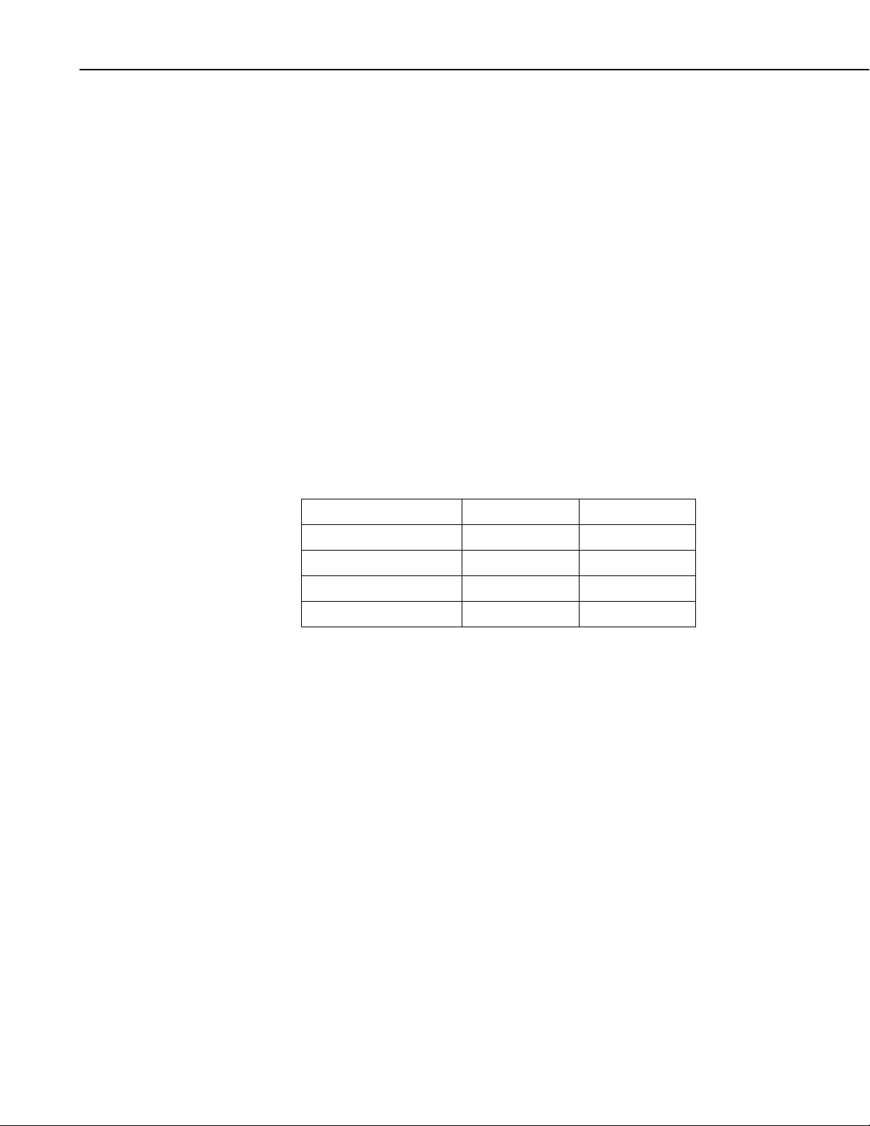
Cable length for the 034B is specified when the sensor is ordered. Table 4.1-1
gives the recommended cable length for mounting the sensor at the top of the
tripod/tower with a CM202 crossarm.
Table 4.1-1 Recommended Cable Length
4.2. Specifications
CM6 CM10 CM110 CM115 CM120 UT10 UT20 UT30
11’ 14’ 14’ 19’ 24’ 14’ 24’ 37’
The 034B Windset ships with:
(1) 1/16” Allen wrench
(1) Bushing from Met One
(1) Calibration Sheet
(3) Direction hub stickers
(1) Resource CD
(1) Wind Vane
(1) Sensor cable of user-specified length
Wind Speed
Operating Range: 0 to 75 m s
Threshold: 0.4 m s
Accuracy:
±0.12 m s
±1.1% of reading for wind speeds > 10.1 m s
-1
(0.9 mph)
-1
(±0.25 mph) for wind speed < 10.1 m s-1 (22.7 mph)
-1
(0 to 167 mph)
-1
(22.7 mph)
Output Signal: contact closure (reed switch)
Resolution: (1.789 mph) / (scan rate in seconds)
or (0.7998 m s
-1
) / (scan rate in seconds)
29
Page 34

Met One 034B Windset
Wind Direction
Measurement Range: 0 to 360°
Threshold: 0.4 m s
Accuracy: ±4°
Resolution: 0.5°
Potentiometer Resistance: 0 to 10 kΩ open at crossover
General Specifications
Operating Temperature Range: -30° to +70°C
Weight: 907 g (2.0 lb.)
-1
(0.9 mph)
NOTE
4.3. Installation
4.3.1 Siting
4.3.2 Assembly and Mounting
The black outer jacket of the cable is Santoprene
compound was chosen for its resistance to temperature extremes,
moisture, and UV degradation. However, this jacket will
support combustion in air. It is rated as slow burning when
tested according to U.L. 94 H.B. and will pass FMVSS302.
Local fire codes may preclude its use inside buildings.
Locate wind sensors away from obstructions (e.g. trees and building). As a
general rule of thumb there should be a horizontal distance of at least ten times
the height of the obstruction between the windset and the obstruction. If it is
necessary to mount the sensors on the roof of a building, the height of the
sensors, above the roof, should be at least 1.5 times the height of the building.
See Section 8 of original 034B manual for a list of references that discuss siting
wind speed and direction sensors.
Tools Required:
®
rubber. This
30
• 1/2” open end wrench (for CM220)
• 5/64” and 1/16” Allen wrenches
• compass and declination angle for the site
• small screw driver provided with datalogger
• UV resistant cable ties
• small pair of diagonal-cutting pliers
• 6 - 10” torpedo level
The wind vane tail must be attached to the hub. Install the tail assembly with
the tail vertical. After tightening the set screw in the side of the hub that
fastens the tail, cover the set screw hole with one of the small round labels
included with the 034B. One of these labels is already installed on the hub
covering the set screw that attaches the hub to the sensor. Extra labels are
included with the 034B to recover the holes if the sensor has to be
disassembled for maintenance.
Page 35

Met One 034B Windset
N
CAUTION
Set screw holes
must be covered
with labels
The set screw holes must be covered with the labels to
prevent corrosion and assure the warranty.
Mount the CM200-series crossarm to the tripod or tower. Orient the crossarm
North-South, with the 1” NU-RAIL or CM220 on the North end.
Remove the alignment screw at the base of the 034B (Figure 4-1). Insert the
034B into the aluminum bushing provided with the sensor. Align the hole in
the bushing with that in the 034B base and replace the screw. Insert the
034B/bushing into the NU-RAIL fitting or the CM220’s u-bolt (Figure 4-2).
Align the sensor so that the counter weight points to true south and tighten the
set screws on the NU-RAIL or U-bolts on the CM220. Remove the shoulder
screw to allow the vane to rotate.
Appendix A of the original 034B manual contains detailed information on
determining true north using a compass and the magnetic declination for the site.
Shoulder
Screw
Alignment
Screw
Bushing
N
Crossarm
FIGURE 4-1. 034B Mounted on a Crossarm Using a 17953 NU-RAIL Crossover Fitting
17953
U-RAIL
31
Page 36

Met One 034B Windset
CM220
CM200 Series Crossarm
4.4. Wiring
FIGURE 4-2. CM200 Series Crossarm with
CM220 Right Angle Mounting Bracket
Attach the sensor cable to the six pin male connector on the 034B. Make sure
the connector is properly keyed. Finger tighten the knurled ring. Route the
sensor cable along the underside of the crossarm to the tripod/tower, and to the
instrument enclosure. Secure the cable to the crossarm and tripod/tower using
cable ties.
Connections to Campbell Scientific dataloggers are given in Table 4.4-1. When
Short Cut for Windows software is used to create the datalogger program, the
sensor should be wired to the channels shown on the wiring diagram created
by Short Cut.
Table 4.4-1 Connections to Campbell Scientific Dataloggers
Color
Wire Label
CR800
CR5000
CR3000
CR1000
CR510
CR500
CR10(X)
21X
CR7
CR23X
CR200(X)
Red WS Signal Pulse Pulse Pulse P_LL
Black WS Signal Ref
G
Green WD Signal SE Analog SE Analog SE Analog SE Analog
Blue WD Volt Excite Excitation
(VX)
White WD Signal Ref
Clear Shield
Excitation Excitation Excitation
(VX)
AG
G
32
Page 37

5. TE525 Tipping Bucket Rain Gage
5.1. General Description
The TE525 is an adaptation of the standard Weather Bureau tipping bucket
rain gage. Output is a switch closure for each bucket tip. Three models are
available:
• TE525 6 in. Collector 0.01 in. tip
• TE525WS 8 in. Collector 0.01 in. tip
• TE525MM 9.6 in Collector 0.1 mm tip
A “–L” after the model number indicates that the cable length is specified
when ordering.
The TE525 ships with:
(1) Calibration sheet
(2) Hose clamps from original mfg
(1) Instruction manual
(3) Screws from original mfg
The 260-953 Alter-Type Wind Screen can be used with the TE525 to minimize
the effects of strong winds.
5.2. Specifications
Range of Indication:
Infinite in increments of tip (least count) of rainfall.
Rainfall per Tip
TE525 0.01 in.
TE525WS 0.01 in.
TE525MM 0.1 mm
Volume per Tip
TE525, TE525MM: 0.16 fl. oz./tip (4.73 ml/tip)
TE525WS: 0.28 fl. oz./tip (8.24 ml/tip)
Accuracy:
Rainfall Rate TE525 TE525WS
Up to 1 in./hr ±1% ±1%
1 to 2 in./hr +0, –3% +0, –2.5%
2 to 3 in./hr +0, –5% +0, –3.5%
Rainfall Rate TE525MM
Up to 10 mm/hr ±1%
10 to 20 mm/hr +0, –3%
20 to 30 mm/hr +0, –5%
33
Page 38

TE525 Tipping Bucket Rain Gage
Signal Output:
Momentary switch closure activated by tipping bucket mechanism.
Calibration/Cleaning Frequency:
Sensor is factory calibrated and should not require field calibration.
Environmental Limits:
Temperature: 0° to +50°C
Humidity: 0 to 100%
Physical Data:
Diameter: 6.25 in. overall
Height
TE525 9.5 in.
TE525WS 12 in.
TE525MM 12 in.
Weight: 2.5 pounds
Funnel: Gold anodized spun aluminum knife edge collector ring and
Funnel Collector Diameter:
TE525 6.064 in.
TE525WS 8 in.
TE525MM 9.664 in.
Resolution: 1 tip
Mounting: Side bracket with clamps for pole or mast mounting
Material: Aluminum
Cable: 2-conductor, shielded cable, length must be specified when
Switch closure is approximately 135 ms.
Debris filters, funnel, and bucket reservoirs should be kept clean. Section
6 describes field calibration check and factory calibration.
funnel assembly.
ordering.
NOTE
5.3. Installation
NOTE
5.3.1 Siting
®
The black outer jacket of the cable is Santoprene
compound was chosen for its resistance to temperature extremes,
moisture, and UV degradation. However, this jacket will
support combustion in air. It is rated as slow burning when
tested according to U.L. 94 H.B. and will pass FMVSS302.
Local fire codes may preclude its use inside buildings.
The 260-953 Alter-Type Wind Screen’s siting information and
installation procedure are provided in our 260-953 manual.
The rain gage should be mounted in a relatively level spot which is
representative of the surrounding area. The lip of the funnel should be
horizontal and at least 30 cm. above the ground. It should be high enough to
be above the average snow depth. The ground surface around the rain gage
should be natural vegetation or gravel. It should not be paved.
rubber. This
34
Page 39

5.3.2 Mounting
TE525 Tipping Bucket Rain Gage
The rain gage should be placed away from objects that obstruct the wind. The
distance should be 2 to 4 times the height of the obstruction.
When leveling, be sure that the funnel is properly seated in the body of the
gage and that:
• the orifice is level
• the body of the sensor is vertical (plumb).
The CM300 Series mounting poles provide a stainless steel 1.5 IPS vertical
pole for mounting the TE525 rain gage. Pole length is 23”, 47”, or 56” for the
CM300, CM305, and CM310 models respectively. The CM300 Series offers
pedestal base options as well.
Use the enclosed hose clamps to mount the gage as shown in Figure 5.3-1. The
lip of the gage should be at least 2 inches above the post or pole. Level the
rain gage after mounting it.
NOTE
Before final leveling, press either end of the bucket down against
its stop to make sure the bucket is NOT hung up in the center.
24”
8”
FIGURE 5.3-1. TE525 Tipping Bucket Rain Gage
35
Page 40

6. LP02 Pyranometer
6.1. General Description
This manual provides information for interfacing Hukseflux’s LP02
Pyranometer to various models of Campbell Scientific dataloggers.
The LP02 is shipped with an instruction manual provided by Hukseflux that
contains information concerning the LP02’s construction, spectral sensitivity,
cosine response, and a simple sensor check out procedure. Included with the
sensor and manual is a calibration certificate with the sensor calibration
constant and serial number. Cross check this serial number against the serial
number on your LP02 to ensure that the given calibration constant corresponds
to your sensor.
The LP02 pyranometer is designed for continuous outdoor use. Due to its flat
spectral sensitivity from 300 to 3000 nm, it can be used in natural sunlight,
under plant canopies, in green houses or buildings, and inverted to measure
reflected solar radiation. Two LP02s can be used in combination to measure
albedo. The LP02 can also be used to measure most types of artificial light
(Xenon lamps, Halogen lamps, etc.).
The LP02 pyranometer consists of a thermopile sensor, housing, dome, and
cable. The thermopile is coated with a black absorbent coating. The paint
absorbs the radiation and converts it to heat. The resultant temperature
difference is converted to a voltage by the copper-constantan thermopile. The
thermopile is encapsulated in the housing in such a way that it has a field of
view of 180 degrees and the angular characteristics needed to fulfill the cosine
response requirements.
6.2. Specifications
The LP02 complies with the ISO Second class pyranometer specifications as
detailed below.
LP02 ISO / WMO Specifications
Overall classification according to ISO
9060 / WMO
Response time for 95 % response 18 s
Zero offset (response to 200 W/m
thermal radiation)
Zero offset (response to 5 k/h change in
ambient temperature)
Non-stability < 1% change per year
Non-Linearity < +/- 2.5%
Directional response for beam radiation: within +/- 25 W/m
1
2
net
Second class pyranometer
< 15 W/m2
<4 W/m
2
2
36
Page 41

LP02 Pyranometer
Spectral selectivity +/- 5% (305 to 2000 nm)
Temperature response
within 6% (-10 to +40°C)
(within an interval of 50°C)
Tilt response within +/- 2%
LP02 ADDITIONAL MEASUREMENT SPECIFICATIONS
Sensitivity 10-40 μV/Wm
-2
Expected voltage output 0.1 to + 50 mV in natural sunlight
Operating temperature
-40 to +80°C
Sensor resistance Between 40 and 60 Ohms
Power required Zero (passive sensor)
Standard cable length 16 ft (4.8 m)
Range 0-2000 Wm
-2
Cable replacement Cable can be replaced by the user
Spectral range 305 to 2800 nm (50% transmission
points)
Required datalogger channels 1 differential or 1 single ended
voltage channel
Leveling Level and leveling feet included
Expected accuracy for daily sums +/- 10%
6.3. Installation
DIMENSIONS / SHIPPING DIMENSIONS
LP02: 3 in dia x 3 in / 8x4x10 in
WEIGHT/SHIPPING WEIGHT
LP02: 0.8 lbs / 1.2 lbs
1
Guide to Meteorological Instruments and Methods of Observation, fifth
edition, WMO, Geneva and ISO9060
The LP02 is usually installed horizontally, but can also be installed at any
angle including an inverted position. In all cases it will measure the flux that is
incident on the surface that is parallel to the sensor surface.
Site the LP02 to allow easy access for maintenance while ideally avoiding any
obstructions above the plane of the sensing element. It is important to mount
the LP02 such that a shadow will not be cast on it at any time.
If this is not possible, try to choose a site where any obstruction over the
azimuth range between earliest sunrise and latest sunset has an elevation not
exceeding 5°. Diffuse solar radiation is less influenced by obstructions near
the horizon. For instance, an obstruction with an elevation of 5° over the
whole azimuth range of 360° decreases the downward diffuse solar radiation
by only 0.8%.
37
Page 42

LP02 Pyranometer
The sensor should be mounted with the cable pointing towards the nearest
magnetic pole, e.g., in the Northern Hemisphere point the cable toward the
North Pole.
The CM225 Solar Sensor Mounting Stand is used to attach the LP02 to a
vertical pipe (1.0 – 2.1” OD) as shown in Figure 6.3-1. The LP02 includes a
base with three leveling screws, bubble level, and mounting screws.
Attach the LP02 to the CM225 as follows:
1. Loosely mount the pyranometer and fixture on the mounting arm, with the
leveling screws lightly touching the mounting plate. Do not fully tighten
the two mounting screws.
2. Turn the leveling screws as required to bring the bubble of the spirit level
within the ring. (For easy leveling first use the screw nearest the spirit
level.)
3. Tighten the mounting screws to secure the assembly in its final position.
Check that the pyranometer is still correctly leveled and adjust as
necessary.
LP02 Pyranometer
Bubble Level
(3) Leveling Screws
CM225 Solar
Sensor
Mounting Stand
(2) Mounting Screws
CM200 Series
Crossarm
FIGURE 6.3-1. LP02 Pyranometer Attached to CM225 Solar Sensor
Mounting Stand
38
Page 43

7. CMP6-L, CMP11-L, and CMP21-L
Pyranometers
6.1. Introduction
CMP-series pyranometers are designed for continuous outdoor monitoring of
solar radiation intensity. A flat spectral sensitivity from 285 to 2800 nm
enables accurate measurements in natural sunlight, under plant canopies, and
in green houses or buildings. When inverted, these pyranometers can measure
reflected solar radiation. Uses include monitoring global horizontal irradiance
(GHI) and plane of array irradiance (POA). Diffuse sky radiation can also be
measured with the use of a shade mechanism.
CMP-series pyranometers are manufactured by Kipp & Zonen, and cabled by
Campbell Scientific.
Before using these pyranometers, please study:
• Section 2, Cautionary Statements
• Section 3, Initial Inspection
• Section 4, Quick Start
More details are available in the remaining sections.
7.2. Cautionary Statements
• CMP-series pyranometers are rugged, but they should be handled as
precision scientific instruments.
• Care should be taken when opening the shipping package to not damage
or cut the cable jacket. If damage to the cable is suspected, consult with a
Campbell Scientific applications engineer.
7.3. Initial Inspection
Check the contents of the shipment. If there is a shortage (see Section 7.3.1,
Ships With), contact Campbell Scientific. If any damage has occurred during
transport, immediately file a claim with the carrier and contact Campbell
Scientific to facilitate repair or replacement.
The model number and cable length are printed on a label at the connection
end of the cable. Check this information against the shipping documents to
ensure the correct product and cable length are received.
39
Page 44

CMP6-L, CMP11-L, and CMP21-L Pyranometers
7.3.1 Ships With
(2) Bolts for mounting from original mfg
(1) Instruction Manual from original mfg
(1) Sun Shield from original mfg
(2) Nylon washers from original mfg
7.3.2 Calibration Certificate
Each pyranometer is shipped with an instruction manual provided by Kipp &
Zonen that contains information concerning its construction, spectral
sensitivity, cosine response, and a simple sensor check out procedure.
Included with the sensor and manual is a calibration certificate with the sensor
sensitivity value and serial number.
NOTE
7.4. Quick Start
NOTE
7.4.1 Siting
Cross check this serial number against the serial number on your
pyranometer to ensure that the given sensitivity value
corresponds to your sensor.
Appendix A in the CMP-series manual provides the installation
procedure for the CVF3 ventilation unit.
The pyranometer is usually installed horizontally for global horizontal
measurements. However, the pyranometer can be installed at any angle for
POA measurements and in the inverted position for reflected measurements.
In all cases it will measure the solar flux incident on the sensor surface.
Site the pyranometer to allow easy access for maintenance while ideally
avoiding any obstructions above the plane of the sensing element. It is
important to mount the pyranometer such that a shadow will not be cast on it at
any time.
If this is not possible, try to choose a site where any obstruction over the
azimuth range between earliest sunrise and latest sunset has an elevation not
exceeding 5°. Diffuse solar radiation is less influenced by obstructions near
the horizon. For instance, an obstruction with an elevation of 5° over the
whole azimuth range of 360° decreases the downward diffuse solar radiation
by only 0.8%.
40
The sensor should be mounted with the cable pointing towards the nearest
magnetic pole (e.g., in the Northern Hemisphere point the cable toward the
North Pole); see Figures 7-1 through 7-4.
Page 45

7.4.2 Mounting
CMP6-L, CMP11-L, and CMP21-L Pyranometers
See Section 7.6.1, Mounting to a Tripod Tower for more information.
CM245 Adjustable
Angle Mounting
Stand
CM2XX-Series
Crossarm
FIGURE 7-1. Pyranometer installation
FIGURE 7-2. Pyranometer mounted horizontally for the Northern
Hem
isphere
(left) and Southern Hemisphere (right)
41
Page 46

CMP6-L, CMP11-L, and CMP21-L Pyranometers
FIGURE 7-3. Two views of a pyranometer mounted at an angle for the
Northern Hemisphere
42
FIGURE 7-4. Pyranometer mounted at an angle for the Southern
isphere
Hem
Page 47

CMP6-L, CMP11-L, and CMP21-L Pyranometers
7.5 Specifications
7.5.1 Pyranometers
TABLE 7-1. CMP-series Specifications
Specification CMP6 CMP11 CMP21
ISO Classification First Class Secondary Standard
Maximum irradiance 2000 W•m-2 4000 W•m-2
Spectral range
(50% points)
Response time (95 %) <18 s <5 s
Expected daily
uncertainty
<5% <2%
Zero offset due to thermal
radiation
-2
(200 W•m
)
Zero offset due to
temperature change
(5 K•hr
-1
)
Non-stability
(change/year)
Non-linearity
(0 to 1000 W•m
-2
)
<15 W•m
<4 W•m
-2
<7 W•m-2
-2
<2 W•m-2
<1 % <0.5%
<1% <0.2%
Directional error
(up to 80° with 1000
-2
W•m
beam)
Tilt error
(at 1000 W•m
-2
)
<20 W•m
-2
<10 W•m-2
<1% <0.2%
Level accuracy 0.1°
Operating temperature -40° to 80°C
Temperature dependence
of sensitivity
<4% (-10° to 40°C) <1% (-20° to 50°C)
Sensitivity 5 to 20 µV / W•m-2 7 to 14 µV / W•m-2
Typical signal output for
atmospheric applications
0 to 20 mV 0 to 15 mV
Weight 0.6 kg (1.3 lb) without cable;
0.9 kg (2 lb) with 10 m (33 ft) cable
Impedance* 20 to 200 Ω 10 to 100 Ω
* Impedance is defined as the total electrical impedance at the radiometer output connector fitted to the housing.
It arises from the electrical resistance in the thermal junctions, wires, and passive electronics within the
radiometer.
285 to 2800 nm
43
Page 48

CMP6-L, CMP11-L, and CMP21-L Pyranometers
FIGURE 7-6. Dimensions of the CMP6, CMP11, and CMP21
7.5.2 CVF3 Ventilation Unit
Compatible Pyanometers: CMP6, CMP11, CMP21
Power supply: 12 Vdc, 1.3 A (with 10 W Heater)
Operating temperature range: -40° to 70°C
Ventilation power: 5 W continuously
Heating power: 5 W and 10 W
Heater induced offset: <1 W•m
Weight without cable: 1.6 kg (3.5 lb)
-2
(with CMP11 Pyranometer)
44
FIGURE 7-7. Dimensions of the CVF3
Page 49

7.6. Installation
7.6.1 Mounting to a Tripod or Tower
CMP6-L, CMP11-L, and CMP21-L Pyranometers
Tools required for installation on a tripod or tower:
Small and medium Phillips screwdrivers
5/16”, 1/2” open end wrenches
5/32” Allen wrench
Tape measure
UV-resistant wire ties
Side-cut pliers
Compass
Step ladder
The pyranometers include a bubble level and two leveling screws, which allow
them to be leveled horizontally without using a leveling base. They mount to a
mast, crossarm, or pole (1.0 in. to 2.1 in. outer diameter) via the CM245
Mounting Stand.
NOTE
If using a CFV3 Ventilation Unit, a different mounting stand, the
27084, is required. Refer to Appendix A for more information.
The CM245 includes slots that allow it to be adjusted to any angle from
horizontal to vertical. If mounting the pyranometer at an angle, ensure that the
crossarm is leveled horizontally before placing the bracket at its proper angle.
Angle positions are included on the bracket label (see Figures 7-8 and 7-9).
Pyranometer
mounts here
First
2.125”
u-bolt
First
Second
2.125”
u-bolt
FIGURE 7-8. CM245 bracket with 2.125” u-bolts positioned to mount
the pyranometer horizontally on a crossarm
2.125”
u-bolt
90
Second
2.125”
u-bolt
45
Page 50

CMP6-L, CMP11-L, and CMP21-L Pyranometers
First
1.5”
u-bolt
40
Second
1.5”
u-bolt
FIGURE 7-9. CM245 bracket with 1.5” u-bolts positioned to mount
pyranometer at a 40° angle on a vertical pipe
Do the following to level the pyranometer horizontally (see Figure 7-10):
1. Attach the mounting stand to the crossarm.
2. Loosely mount the pyranometer on the mounting stand. Do not fully
tighten the two mounting screws.
3. Turn the leveling screws as required to bring the bubble of the level within
the ring.
4. Tighten the mounting screws to secure the assembly in its final position.
Check that the pyranometer is still correctly leveled and adjust as
necessary.
5. Attach the white plastic sun screen to the pyranometer.
46
Page 51

Mounting screws
N
Levelling screw
CMP6-L, CMP11-L, and CMP21-L Pyranometers
Sun shield
ylon washers
Bubble level
Pyranometer
mounting st
7.6.2 Wiring
NOTE
CM
245
and
Crossarm
FIGURE 7-10 Exploded view of the pyranometer mounting
Short Cut users should wire the sensor according to the wiring
diagram generated by Short Cut.
The cable of the CMP6 and CMP11 has two conductors and a shield. The
cable of the CMP21 has five conductors and a shield. The additional
conductors on the CMP21’s cable are for connecting its internal thermistor. A
schematic for the CMP6, CMP11, and the thermopile of the CMP21 is
provided in Section 6.6.2.1. Wiring for the CMP6 and CMP11 is described in
Section 6.6.2.2; wiring for the CMP21 is described in Section 7.6.2.3.
47
Page 52

CMP6-L, CMP11-L, and CMP21-L Pyranometers
(-)
(+)
7.6.2.1 CMP6, CMP11, and CMP21 Thermopile Schematic
A schematic diagram of a CMP6, CMP11, or CMP21 thermopile is shown in
Figure 7-11.
White
Red
Black
Blue
Black
Shield
FIGURE 7-11. CMP6, CMP11, and CMP21 thermopile detector
schematic
7.6.2.2 CMP6 and CMP11 Wiring
NOTE
A CMP6 or CMP11 purchased from Campbell Scientific has
different wiring than a pyranometer purchased directly from
Kipp & Zonen.
The pyranometer is measured using either differential analog channels or
single-ended analog channels.
A differential voltage measurement is recommended because it has better noise
rejection than a single-ended measurement.
Connections to Campbell Scientific dataloggers for a differential measurement
are given in Table 7-2. A user-supplied jumper wire should be connected
between the low side of the differential input and ground (AG or
) to keep
the signal in common mode range.
Connections to Campbell Scientific dataloggers for a single-ended
measurement are given in Table 7-3.
Dataloggers
21X, CR7, CR23X
Color
TABLE 7-2. CMP6 and CMP11 Differential Connections to Campbell Scientific
Description
CR9000(X), CR5000,
CR3000, CR1000,
CR800
CR510, CR500,
CR10(X)
White Signal (+) DIFF Analog High DIFF Analog High DIFF Analog High
Black Signal (-) *DIFF Analog Low *DIFF Analog Low *DIFF Analog Low
Shield Shield
* Jumper to AG or
with user supplied 26 AWG or larger wire.
G
48
Page 53

CMP6-L, CMP11-L, and CMP21-L Pyranometers
TABLE 7-3. CMP6 and CMP11 Single-Ended Connections to Campbell Scientific Dataloggers
Color
Description
CR9000(X), CR5000,
CR3000, CR1000,
CR800
CR510, CR500,
CR10(X)
21X, CR7, CR23X
White Signal (+) SE Analog SE Analog SE Analog
Black Signal (-)
Clear Shield
AG
G
7.6.2.3 CMP21 Wiring
NOTE
A CMP21 purchased from Campbell Scientific has different
wiring than a CMP21 purchased directly from Kipp & Zonen.
The CMP21’s pyranometer can be measured using either differential analog
channels or single-ended analog channels. A differential voltage measurement
is recommended because it has better noise rejection than a single-ended
measurement. If a differential channel is not available, a single-ended
measurement can be used.
A single-ended channel and a voltage excitation channel are used to measure
the CMP21’s internal thermistor.
Connections to Campbell Scientific dataloggers for a differential measurement
are given in Table 7-4. A user-supplied jumper wire should be connected
between the low side of the differential input and ground (AG or
) to keep
the signal in common mode range. Connections to Campbell Scientific
dataloggers for a single-ended measurement are given in Table 7-5.
TABLE 7-4. CMP21 Differential Connections to Campbell Scientific Dataloggers
Wire Color
Wire Label/
Description
CR9000(X),
CR5000, CR3000,
CR1000, CR800
CR510, CR500,
CR10(X)
21X, CR7, CR23X
White Pyranometer Sig DIFF Analog High DIFF Analog High DIFF Analog High
Blue Pyranometer Ref *DIFF Analog Low *DIFF Analog Low *DIFF Analog Low
Yellow Thermistor Volt Excite VX or EX E EX
Black Thermistor Sig Single-ended analog Single-ended analog Single-ended analog
Brown Thermistor Ref
Clear Shield
* Jumper to AG or
with user-supplied wire.
AG
G
49
Page 54

CMP6-L, CMP11-L, and CMP21-L Pyranometers
TABLE 7-5. CMP21 Single-Ended Connections to Campbell Scientific Dataloggers
Wire Color
Wire Label/
Description
CR9000(X),
CR5000, CR3000,
CR1000, CR800
CR510, CR500,
CR10(X)
21X, CR7, CR23X
White Pyranometer Sig Single-ended analog Single-ended analog Single-ended analog
Blue Pyranometer Ref
AG
Yellow Thermistor Volt Excite VX or EX E EX
Black Thermistor Sig Single-ended analog Single-ended analog Single-ended analog
Brown Thermistor Ref
Clear Shield
AG
G
50
Page 55

Appendix A. Cut Sheets
A-1
Page 56

CR1000 Speci cations
Electrical speci cations are valid over a -25° to +50°C range unless otherwise speci ed; non-condensing environment required. To maintain electrical
speci cations, Campbell Scienti c recommends recalibrating dataloggers every two years. We recommend that the system con guration and critical
speci cations are con rmed with Campbell Scienti c before purchase.
PROGRAM EXECUTION RATE
10 ms to one day @ 10 ms increments
ANALOG INPUTS (SE1-SE16 or DIFF1-DIFF8)
8 differential (DF) or 16 single-ended (SE) individually
configured. Channel expansion provided by AM16/32B
and AM25T multiplexers.
RANGES and RESOLUTION: Basic resolution
(Basic Res) is the A/D resolution of a single
conversion. Resolution of DF measurements
with input reversal is half the Basic Res.
Range (mV)1DF Res (µV) 2Basic Res (µV)
±5000 667 1333
±2500 333 667
±250 33.3 66.7
±25 3.33 6.7
±7.5 1.0 2.0
±2.5 0.33 0.67
1
Range overhead of ~9% on all ranges guarantees that
full-scale values will not cause over range.
2
Resolution of DF measurements with input reversal.
ACCURACY3:
±(0.06% of reading + offset), 0° to 40°C
±(0.12% of reading + offset), -25° to 50°C
±(0.18% of reading + offset), -55° to 85°C (-XT only)
3
Accuracy does not include the sensor and measurement
noise. The offsets are defined as:
Offset for DF w/input reversal = 1.5·Basic Res + 1.0 µV
Offset for DF w/o input reversal = 3·Basic Res + 2.0 µV
Offset for SE = 3·Basic Res + 3.0 µV
INPUT NOISE VOLTAGE: For DF measurements
with input reversal on ±2.5 mV input range; digital
resolution dominates for higher ranges.
250 µs Integration: 0.34 µV RMS
50/60 Hz Integration: 0.19 µV RMS
ANALOG MEASUREMENT SPEED:
5
Integra-
tion Type/
60 Hz
50 Hz
4
AC line noise filter.
5
Includes 250 µs for conversion to engineering units.
Integra-
Code
tion Time
250 250 µs 450 µs
4
16.67 ms 3 ms
4
20.00 ms 3 ms
Settling
Time
Total Time
SE w/
No Rev
DF w/
Input Rev
~1 ms ~12 ms
~20 ms ~40 ms
~25 ms
~50 ms
INPUT LIMITS: ±5 V
DC COMMON MODE REJECTION: >100 dB
NORMAL MODE REJECTION: 70 dB @ 60 Hz
when using 60 Hz rejection
SUSTAINED INPUT VOLTAGE W/O DAMAGE:
±16 Vdc max.
INPUT CURRENT: ±1 nA typical, ±6 nA max.
@ 50°C; ±90 nA @ 85°C
INPUT RESISTANCE: 20 Gohms typical
ACCURACY OF BUILT-IN REFERENCE JUNCTION
THERMISTOR (for thermocouple measurements):
±0.3°C, -25° to 50°C
±0.8°C, -55° to 85°C (-XT only)
ANALOG OUTPUTS (Vx1-Vx3)
3 switched voltage, active only during measurement,
one at a time.
RANGE AND RESOLUTION: Voltage outputs program mable between ±2.5 V with 0.67 mV resolution.
ACCURACY: ±(0.06% of setting + 0.8 mV), 0° to 40°C
V
x
±(0.12% of setting + 0.8 mV), -25° to 50°C
±(0.18% of setting + 0.8 mV), -55° to 85°C (-XT only)
V
FREQUENCY SWEEP FUNCTION: Switched outputs
x
provide a programmable swept frequency, 0 to 2500 mv
square waves for exciting vibrating wire transducers.
CURRENT SOURCING/SINKING: ±25 mA
RESISTANCE MEASUREMENTS
MEASUREMENT TYPES: The CR1000 provides
ratiometric measurements of 4- and 6-wire full
bridges, and 2-, 3-, and 4-wire half bridges.
Precise, dual polarity excitation using any of the
3 switched voltage excitations eliminates dc errors.
VOLTAGE RATIO ACCURACY
6
: Assuming excitation
voltage of at least 1000 mV, not including bridge
resistor error.
±(0.04% of voltage reading + offset)/V
6
Accuracy does not include the sensor and measurement
noise. The offsets are defined as:
Offset for DF w/input reversal = 1.5·Basic Res + 1.0 µV
Offset for DF w/o input reversal = 3·Basic Res + 2.0 µV
Offset for SE = 3·Basic Res + 3.0 µV
x
Offset values are reduced by a factor of 2 when
excitation reversal is used.
PERIOD AVERAGE
Any of the16 SE analog inputs can be used for period
averaging. Accuracy is ±(0.01% of reading + resolution), where resolution is 136 ns divided by the specified number of cycles to be measured.
INPUT AMPLITUDE AND FREQUENCY:
7
Signal (peak to peak)
Input
Voltage
Range
Gain
(±mV)
1 2500 500 10 2.5 200
10 250 10 2 10 50
33 25 5 2 62 8
100 2.5 2 2 100 5
7
With signal centered at the datalogger ground.
8
The maximum frequency = 1/(Twice Minimum Pulse Width)
for 50% of duty cycle signals.
Min
Pulse
Width
(µV)
PULSE COUNTERS (P1-P2)
(2) inputs individually selectable for switch closure, high
frequency pulse, or low-level ac. Independent 24-bit
counters for each input.
MAXIMUM COUNTS PER SCAN: 16.7x10
6
SWITCH CLOSURE MODE:
Minimum Switch Closed Time: 5 ms
Minimum Switch Open Time: 6 ms
Max. Bounce Time: 1 ms open w/o being counted
HIGH-FREQUENCY PULSE MODE:
Maximum Input Frequency: 250 kHz
Maximum Input Voltage: ±20 V
Voltage Thresholds: Count upon transition from
below 0.9 V to above 2.2 V after input filter with
1.2 µs time constant.
LOW-LEVEL AC MODE: Internal AC coupling removes
AC offsets up to ±0.5 V.
Input Hysteresis: 12 mV @ 1 Hz
Maximum ac Input Voltage: ±20 V
Minimum ac Input Voltage:
Sine Wave (mV RMS) Range(Hz)
20 1.0 to 20
200 0.5 to 200
2000 0.3 to 10,000
5000 0.3 to 20,000
DIGITAL I/O PORTS (C1-C8)
8 ports software selectable, as binary inputs or control outputs. Also provide edge timing, subroutine interrupts/wake
up, switch closure pulse counting, high frequency pulse
counting, asynchronous communications (UART), SDI-12
communications, and SDM communications.
HIGH-FREQUENCY MAX: 400 kHz
SWITCH CLOSURE FREQUENCY MAX: 150 Hz
EDGE TIMING RESOLUTION: 540 ns
OUTPUT VOLTAGES (no load): high 5.0 V ±0.1 V;
low <0.1
OUTPUT RESISTANCE: 330 ohms
INPUT STATE: high 3.8 to 16 V; low -8.0 to 1.2 V
INPUT HYSTERESIS: 1.4 V
INPUT RESISTANCE: 100 kohms
SWITCHED 12 V (SW-12)
One independent 12 V unregulated sources switched on
and off under program control. Thermal fuse hold current
= 900 mA @ 20°C, 650 mA @ 50°C, 360 mA @ 85°C.
CE COMPLIANCE
STANDARD(S) TO WHICH CONFORMITY IS
DECLARED: IEC61326:2002
COMMUNICATIONS
RS-232 PORTS:
9-pin: DCE port for battery-powered computer or
non-CSI modem connection.
COM1 to COM4: Four independent Tx/Rx pairs on
control ports (non-isolated); 0 to 5 VUART
Baud Rates: selectable from 300 bps to 115.2 kbps.
Default Format: 8 data bits; 1 stop bits; no parity
Optional Formats: 7 data bits; 2 stop bits; odd, even
parity
Max8
Freq
CS I/O PORT: Interface with CSI peripherals
(kHz) Min. (mV) Max (V)
SDI-12: Digital control ports 1, 3, 5, and 7 are
individually configured and meet SDI-12 Standard
version 1.3 for datalogger mode. Up to ten SDI-12
sensors are supported per por t.
PERIPHERAL PORT: 40-pin interface for attaching
CompactFlash or Ethernet peripherals
PROTOCOLS SUPPORTED: PakBus, Modbus, DNP3,
FTP, HTTP, XML, POP3, SMTP, Telnet, NTCIP, NTP,
SDI-12, SDM
CPU AND INTERFACE
PROCESSOR: Renesas H8S 2322 (16-bit CPU with
32-bit internal core)
MEMORY: 2 MB of Flash for operating system; 4 MB
of battery-backed SRAM for CPU usage, program
storage and data storage.
CLOCK ACCURACY: ±3 min. per year. Correction
via GPS optional.
SYSTEM POWER REQUIREMENTS
VOLTAGE: 9.6 to 16 Vdc (reverse polarity protected)
EXTERNAL BATTERIES: 12 Vdc nominal
TYPICAL CURRENT DRAIN:
Sleep Mode: 0.7 mA (0.9 mA max.)
1 Hz Sample Rate
100 Hz Sample Rate
100 Hz Sample Rate
(1 fast SE meas.): 1 mA
(1 fast SE meas.): 16.2 mA
(1 fast SE meas. w/RS-232
communication): 27.6 mA
Optional Keyboard Display On (no backlight): add
7 mA to current drain
Optional Keyboard Display On (backlight on): add
100 mA to current drain
PHYSICAL
DIMENSIONS: 9.4" x 4" x 2.4" (23.9 x 10.2 x 6.1 cm);
additional clearance required for serial cable and
sensor leads.
WEIGHT: 2.1 lbs (1 kg)
WARRANTY
3-years against defects in materials and workmanship.
Page 57

CH100 and PS100
12 Vdc Regulator and Power Supply
Speci cations*
Output Voltage: 12 Vdc
Nominal Capacity: 7 Amp hours
Input Voltage
(CHG terminals): 15 to 28 VDC or 18 VAC RMS
Battery Connections
Charging Output Voltage: Temperature compensated
oat charge for battery
Temperature
Compensation Range: -40º to +60ºC
Max. Charging Current: 1.2 A (allows one SP20 or SP10
to be used)
Power Out (+12 terminals)
Voltage: Unregulated 12 V from battery
Temperature
Current Limited with
3 A Thermal Fuse: > 3 A @ < 20°C; 3 A @ 20°C;
2.1A @ 50°C; 1.8 A @ 60°C
The CH100 controls the current owing to the battery and pre-
vents the battery current from owing to the charging source.
CH100 Weight: 5.5 oz. (158 g)
CH100 Dimensions
Height: 4.0” (10.2 cm)
Width: 2.76” (7.0 cm)
Depth: 1.5” (3.9 cm)
PS100 Weight: 6.9 lb (3.1 kg)
PS100 Dimensions (including mounts and connectors)
Height: 4.1” (10.5 cm)
Width: 7.6” (19.0 cm)
Depth: 2.8” (7.0cm)
Page 58

CH200 and PS200
Smart Charging Regulator and Power Supply
Speci cations
CHARGE - CHARGE Terminals (AC or DC Source)
AC: 18 to 24 V RMS with
1.2 A RMS maximum
DC: 16 to 40 Vdc with
1.1 A DC maximum
SOLAR - Terminals1 (Solar Panel or Other DC Source)
Input Voltage Range: 15 to 40 Vdc
Maximum Charging Current: 3.6 Adc typical;
2.8 Adc to 4.3 Adc depending
on individual charger
Operational Temperature2: -40° to +60°C
Quiescent Current
No Charge Source Present: 300 μA maximum
No Battery Connected: 2 mA maximum
Dimensions
PS200: 4.2 x 7.5 x 3 in.
(10.6 x 19 x 7.6 cm)
CH200: 3.9 x 3 x 1.5 in.
(10 x 7.5 x 3.7 cm)
Battery Charging
CYCLE Charging: Vbatt(T) = 14.70 V –(24 mV) x (T – 25°C)
FLOAT Charging: Vbatt(T ) = 13.65 V – (18 mV) x (T – 25°C)
Accuracy: ±1% accuracy on charging
voltage over –40° to +60°C
Power Out (+12 terminals)
Voltage: Unregulated 12 V from battery
4 A Self-Resettable Thermal Fuse Hold Current Limits
<20°C: > 4 A
20°C: 4.0 A
50°C: 3.1 A
60°C: 2.7 A
Measurements
Average Battery Voltage: ±(1% of reading +15 mV)
over –40° to +60°C range
Average Battery/Load Current
Regulator Input Voltage4: ±(2% of reading +2 mA)
over –40° to +60°C range
Solar5: ±(1% of reading - 0.25 V) /
-(1% of reading +1 V)
over –40° to +60°C range
Continuous6: ±(1% of reading - 0.5 V) /
-(1% of reading +2 V)
over –40° to +60°C range
Charger Temperature: ± 2°C
3
At right is a top view
of a CH200 showing its
A CR1000 is connected to the PS200 ‘s SDI-12 terminal allowing
the CR1000 to receive the PS200’s charging, load, battery volt-
age, and current information.
1
Battery voltages below 8.7 V may result in <3.0 A current limit because of fold-back current limit.
2
VRLA battery manufacturers state that “heat kills batteries” and recommend operating batteries ≤50°C.
3
Two-step temperature compensated constant- voltage charging for valve-regulated lead-acid batteries. Cycle and oat charging voltage
parameters are programmable with the default values listed.
4
Impulse type changes in current may have an average current error of ±(10% of reading + 2 mA).
5.
1.0 V negative o set is worst-case due to reversal protection diode on input. Typical diode drop is 0.35 V.
6.
2.0 V negative o set is worst-case due to two series diodes in AC full-bridge. Typical diode drops are 0.35 V each for 0.7 V total.
LEDs and terminals.
Page 59

CM106
Instrumentation Tripod
Speci cations
Measurement Height
Upper Mast Retracted: 7 ft (2.1 m)
Upper Mast Extended: 10 ft (3 m)
Vertical Load Limit: 100 lb (45 kg)
Mast Outer Diameter
Main Lower Mast: 1.90 in. (48 mm)
Retractable Upper: 1.74 in. (44 mm)
Base Diameter: 9.3 ft (2.8 m)
Leveling Adjustment: Slide collars on each leg
adjust individually
Leg Base: 4 in. by 5 in. with four 0.62 in.
holes for ground stake
Portability: Collapsible to 8 in. diameter
by 6 ft length
Weight with Mast: 40 lb (18 kg)
Maximum Slope Angle*: 22° or 40% grade
Allowable Wind Speeds**
Tripod
Con guration
Mast Extended,
Unguyed
Mast Retracted,
Unguyed
Mast Extended,
Guyed
Mast Retracted,
Guyed
Sustained Wind Wind Gust
65 mph (29 m/s) 84 mph (38 m/s)
80 mph (36 m/s) 104 mph (46 m/s)
100 mph (45 m/s) 130 mph (58 m/s)
115 mph (51 m/s) 150 mph (67 m/s)
A close up of the adjustable leg clamp.
A CM106 with the optional guy kit and
an enclosure mounted to the leg base.
Page 60

BP84
84 Ah Rechargeable Battery
Speci cations
Output Voltage: 12 Vdc
Nominal Capacity: 84 Amp hours when dis-
charged at a 24 hour rate
Temperature Range: -40° to +71°C
Weight
Battery Only: 55 lbs (25 kg)
Battery Only (shipping): 57 lbs (25.9 kg)
Either Mounting Bracket: 2 lbs (0.9 kg)
Dimensions
Battery Shipping Box: 8” x 13” x 14”
(20.3 x 33 x 35.6 cm)
BP84 Bracket: 3” x 9” x 11”
(7.6 x 22.9 x 27.9 cm)
The BP84 bracket is mounted inside an ENC16/18 with a sideplate
(option -SB) and two vertical cable conduits (option -VC). It is convenient to mount the 18529 SunSaver regulator on the sideplate.
The 25962 is the 84 Ah battery included with the BP84 and PS84.
It can be purchased separately as a replacement part.
Page 61

UT10 Speci cations
Required Concrete Pad
Dimensions (see note 2): 24 x 24 x 24 in. (61 x 61 x 61 cm)
Crossarm Height (attached to mast)
Standard: 10 ft (3 m)
Maximum (mast
fully extended): ~12 ft (3.7 m)
Minimum: ~9 ft (2.7 m)
Wind Load Recommendation
(see note 3): 110 mph maximum
Wind Sentry Set
Crossarm
HMP45C-L6 Temperature and RH Probe
housed in a Radiation Shield
Pipes Outer Diameter (OD)
Vertical: 1 in. (2.5 cm)
Cross Support: 0.375 in. (0.953 cm)
Leg Spacing: 10.25 in. (26 cm) between legs
(center to center)
Material: Aluminum
Shipping Weight: 40 lbs (18 kg)
Lightning Rod (included w/UT10)
LI200X Pyranometer,
Pyranometer Crossarm Stand,
LI2003S Pyranometer Base and Leveling Fixture
Solar Panel
Environmental Enclosure
Anchor Bolt (included w/UT10)
Hinged Base (included w/UT10)
User-supplied Concrete Pad
Anchor Bolts (included w/UT10)
Notes:
1. Refer to the "Instrumentation Mounts" product brochure for crossarm, solar radiation mounts, and radiation shield options.
2. e concrete pad requirements assume heavy soil; light, shi ing, or sandy soils require a larger concrete pad.
3. e wind load recommendation assumes proper installation, proper anchoring, adequate soil, and total instrument projected area of less
than 2 square feet. e amount of wind load that this mount can withstand is a ected by quality of anchoring and installation, soil type,
and the number, type, and location of instruments fastened to the UT10.
TE525-L50 Tipping Bucket Rain Gage
5-ft Grounding Rod (included w/UT10)
Page 62

NL115
Ethernet Interface and CompactFlash® Module
Speci cations
Compliance: CE Compliant
Power Requirements: 12 V supplied through the data-
logger’s peripheral port
Current Drain: 20 mA (CR1000 w/NL115 com-
municating over Ethernet)
43 mA (CR1000 w/NL115 com municating over Ethernet and
accessing CF-card)
Temperature Range
Standard: -25° to +50°C
Extended: -40° to +85°C
EMI and ESD Protection: Meets requirements for a
class A device under
European Standards
Application of
Council Directive(s): 89/336/EEC as amended by
89/336/EEC and 93/68/EEC
Standards to which
Conformity is Declared: EN55022-1; 1995 and
EN50082-1: 1992
Typical Access Speed2: 200 to 400 kbits s
Memory Con guration: User selectable; ring (default) or
ll-and-stop
Datalogger Operating
System (OS): The CR1000’s OS must be OS 9 or
later. Both the CR1000 and
CR3000 need OS 25 or later
to read cards with more than
2 GB of storage.
-1
Software Requirements
LoggerNet: Version 3.2 or later
PC400: Version 1.3 or later
DevCon g: Version 1.5 or later
Cable Requirements: Ethernet cable must be shielded
if the length is greater than 9 ft
CF Card Requiremen
Dimensions: 10.2 x 8.9 x 6.4 cm
(4.0 x 3.5 x 2.5 in.)
Weight: 154 g (5.4 oz)
ts: Industrial grade
2
Typical Access Speed varies between dataloggers.
CR1000
NL115 connects
directly to the
peripheral port
Page 63

NL120
10baseT Ethernet Module
Speci cations
Power Requirements: 12 V supplied through the data-
logger’s peripheral port
Current Drain: 20 mA
Temperature Range
Standard: -25° to +50°C
Extended: -40° to +85°C
Software Requirements
LoggerNet: Version 3.2 or later
PC400: Version 1.3 or later
DevCon g: Version 1.5 or later
Cable Requirements: Ethernet cable must be shielded
if the length is greater than 9 ft
EMI and ESD Protection: Meets requirements for a
class A device under
European Standards
Application of
Council Directive(s): 89/336/EEC as amended by
89/336/EEC and 93/68/EEC
Standards to which
Conformity is Declared: EN55022-1; 1995 and
EN50082-1: 1992
Dimensions: 10.2 x 2.8 x 6.4 cm
(4.0 x 1.1 x 2.5 in.)
Weight: 66.62 g (2.4 oz)
NL120 connects directly
to the peripheral port
CR1000
15 W 1800 N | Logan, UT 84321-1784 | (435) 227-9000 | www.campbellsci.com
Campbell Scientic, Inc. | 815 W 1800 N | Logan, UT 84321-1784 | (435) 227-9000 | www.campbellsci.com
AUSTRALIA | BRAZIL | CANADA | COSTA RICA | ENGLAND | FRANCE | GERMANY | SOUTH AFRICA | SPAIN | USA
AUSTRALIA | BRAZIL | CANADA | COSTA RICA | ENGLAND | FRANCE | GERMANY | SOUTH AFRICA | SPAIN | USA
Copyright © 2009, 2012
Copopyright ©
Campbell Scientifi c, Inc.
CamCampbell Sc
Printed March 2012
Printed M
Page 64

RavenXT-Series
Sierra Wireless Airlink Digital Cellular Modems
Speci cations
RavenXTV RavenXTG
Technology CDMA 1xRTT, EVDO Rev. A, CDMA IS-95,
dual band
Bands Dual band: 800 MHz Cellular,
1900 MHz PCS
Transmit Frequency 1850 to 1910 MHz and 824 to 849 MHz 850/1900 MHz: 824 to 849 MHz;
Transmit Power 1.0 W for 1900 MHz; 0.8 W for 850 MHz 1.0 W for 1900 MHz; 0.8 W for 850 MHz
Receiver Frequency 1930 to 1990 MHz and 869 to 894 MHz 850/1900 MHz: 869 to 894 MHz;
CDMA or GPRS Throughput up to 80 kbps (CDMA) up to 70 kbps (GPRS)
RS-232 Data Rates 1200 bps to 115.2 kbps 1200 bps to 115.2 kbps
Serial Interface RS-232, DB9-F RS-232, DB9-F
Serial Protocols AT Commands, PPP, SLIP, UDP/IP, TCP/IP AT Commands, PPP, SLIP, UDP, TCP
RF Antenna Connector 50 Ohm SMA 50 Ohm SMA
Input Current Range 50 to 250 mA 40 to 250 mA
Typical Current Drain (at 12 Vdc) 50 mA dormant (idle for 10 to 20 seconds),
120 mA transmit/receive
Input Voltage Range 6 to 28 Vdc 6 to 28 Vdc
Operating Temperature Range -30° to +70°C -30° to +65°C
Operating Humidity Range 5% to 95% RH non-condensing 5% to 95% RH non-condensing
Status LEDs Power, Network, Signal, Activity Power, Network, Signal, Activity
Width 7.6 cm (3 in.) 7.6 cm (3 in.)
Depth 2.5 cm (1 in.) 2.5 cm (1 in.)
Length 10 cm (4 in.) 10 cm (4 in.)
Weight <0.5 kg (<1 lb) <0.5 kg (<1 lb)
GPRS (MS-12), quad band
Quad band: 850/1900 MHz;
900/1800 MHz
1850 to 1910 MHz
900/1800 MHz: 890 to 915 MHz;
1710 to 1785 MHz
1930 to 1990 MHz
900/1800 MHz: 935 to 960 MHz;
1805 to 1880 MHz
50 mA dormant (idle for 10 to 20 seconds),
120 mA transmit/receive
Page 65

CM245 and CVF3
Mounts for CMP-Series Pyranometers
CM245 Adjustable Angle, Mounting Stand
Compatible Pipes: 1 to 2.1 in. outer diameter
Slots in the CM245 mount can be adjusted to any angle from
horizontal to vertical.
Outer glass dome
Inner glass dome
Sun Shield
CM245
Mount
Crossarm
The pyranometer is typically mounted and leveled horizontally.
CVF3 Heater/Ventilator
Power Supply: 12 Vdc, 1.3 A (with 10 W Heater)
Operating Temperature: -40° to +70°C
Ventilation Power: 5 W continuously
Heating Power: 5 W or 10 W
Heater Induced O set: <1 W/m2 (with CMP11)
Weight without cable: 3.5 lb (1.6 kg)
Dimensions
Height: 5.1 in. (12.9 cm)
Diameter: 8.8 in. (22.4 cm)
Transparent view of the CVF3 shows air drawn and heated over
the pyranometer.
 Loading...