

Page 1

Revision: 02/2021
Copyright © 2019 – 2021
Campbell Scientific
CSL I.D - 1298
Page 2

Guarantee
This equipment is guaranteed against defects in materials and workmanship.
We will repair or replace products which prove to be defective during the
guarantee period as detailed on your invoice, provided they are returned to us
prepaid. The guarantee will not apply to:
Equipment which has been modified or altered in any way without the
written permission of Campbell Scientific
Batteries
Any product which has been subjected to misuse, neglect, acts of God or
damage in transit.
Campbell Scientific will return guaranteed equipment by surface carrier
prepaid. Campbell Scientific will not reimburse the claimant for costs incurred
in removing and/or reinstalling equipment. This guarantee and the Company’s
obligation thereunder is in lieu of all other guarantees, expressed or implied,
including those of suitability and fitness for a particular purpose. Campbell
Scientific is not liable for consequential damage.
Please inform us before returning equipment and obtain a Repair Reference
Number whether the repair is under guarantee or not. Please state the faults as
clearly as possible, and if the product is out of the guarantee period it should
be accompanied by a purchase order. Quotations for repairs can be given on
request. It is the policy of Campbell Scientific to protect the health of its
employees and provide a safe working environment, in support of this policy a
“Declaration of Hazardous Material and Decontamination” form will be
issued for completion.
When returning equipment, the Repair Reference Number must be clearly
marked on the outside of the package. Complete the “Declaration of
Hazardous Material and Decontamination” form and ensure a completed copy
is returned with your goods. Please note your Repair may not be processed if
you do not include a copy of this form and Campbell Scientific Ltd reserves
the right to return goods at the customers’ expense.
Note that goods sent air freight are subject to Customs clearance fees which
Campbell Scientific will charge to customers. In many cases, these charges are
greater than the cost of the repair.
Campbell Scientific Ltd,
80 Hathern Road,
Shepshed, Loughborough, LE12 9GX, UK
Tel: +44 (0) 1509 601141
Fax: +44 (0) 1509 270924
Email: support@campbellsci.co.uk
www.campbellsci.co.uk
Page 3
About this manual
Please note that this manual was originally produced by Campbell Scientific Inc. primarily for the North
American market. Some spellings, weights and measures may reflect this origin.
Some useful conversion factors:
Area: 1 in2 (square inch) = 645 mm2
Length: 1 in. (inch) = 25.4 mm
1 ft (foot) = 304.8 mm
1 yard = 0.914 m
1 mile = 1.609 km
In addition, while most of the information in the manual is correct for all countries, certain information
is specific to the North American market and so may not be applicable to European users.
Differences include the U.S standard external power supply details where some information (for
example the AC transformer input voltage) will not be applicable for British/European use. Please note,
however, that when a power supply adapter is ordered it will be suitable for use in your country.
Reference to some radio transmitters, digital cell phones and aerials may also not be applicable
according to your locality.
Some brackets, shields and enclosure options, including wiring, are not sold as standard items in the
European market; in some cases alternatives are offered. Details of the alternatives will be covered in
separate manuals.
Part numbers prefixed with a “#” symbol are special order parts for use with non-EU variants or for
special installations. Please quote the full part number with the # when ordering.
Mass: 1 oz. (ounce) = 28.35 g
1 lb (pound weight) = 0.454 kg
Pressure: 1 psi (lb/in2) = 68.95 mb
Volume: 1 UK pint = 568.3 ml
1 UK gallon = 4.546 litres
1 US gallon = 3.785 litres
Recycling information
At the end of this product’s life it should not be put in commercial or domestic refuse but
sent for recycling. Any batteries contained within the product or used during the
products life should be removed from the product and also be sent to an appropriate
recycling facility.
Campbell Scientific Ltd can advise on the recycling of the equipment and in some cases
arrange collection and the correct disposal of it, although charges may apply for some
items or territories.
For further advice or support, please contact Campbell Scientific Ltd, or your local agent.
Campbell Scientific Ltd, 80 Hathern Road, Shepshed, Loughborough, LE12 9GX,
UK Tel: +44 (0) 1509 601141 Fax: +44 (0) 1509 270924
Email: support@campbellsci.co.uk
www.campbellsci.co.uk
Page 4

Safety
DANGER — MANY HAZARD S ARE ASSOCIATED WITH INSTALLING, USING, M AINTAINING, AND WORKING ON
OR AROUND TRIPODS, TOWERS, AND ANY ATTACHMENTS TO TRIPODS AND TOWERS SUCH AS SENSORS,
CROSSARMS, ENCLOSURES, ANTENNAS, ETC. FAILURE TO PROPERLY AND COM P LE TE LY ASS E M BLE ,
INSTALL, OPERATE, USE, AND MAINTAIN TRIPODS, TOWERS, AND ATTACHMENTS, AND FAILURE TO HEED
WARNINGS, INCREASES THE RISK OF DEATH, ACCIDENT, SERIOUS INJURY, PROPERTY DAMAGE, AND
PRODUCT FAILURE. TAKE ALL REASONABLE PRECAUTIONS TO AVOID THESE HAZARDS. CHECK WITH YOUR
ORGANIZATION'S SAFETY COORDINATOR (OR POLICY) FOR PROCEDURES AND REQUIRED PROTECTIVE
EQUIPMENT PRIOR TO PERFORMING ANY WORK.
Use tripods, towers, and attachments to tripods and towers only for purposes for which they are designed. Do not
exceed design limits. Be familiar and comply with all instructions provided in product manuals. Manuals are
available at www.campbellsci.eu or by telephoning +44(0) 1509 828 888 (UK). You are responsible for conformance
with governing codes and regulati ons, including safety regulati ons, and the integrity and locati on of structures or land
to which towers, tripods, and any attachments are attached. Installation sites should be evaluated and approved by a
qualified engineer. If questions or co ncerns arise regarding installation, use, or maintenance of tripods, towers,
attachments, or electrical connections, consult with a licensed and qualified engineer or electrician.
General
• Prior to performing site or installation work, obtain required approvals and permits. Comply with all
governing structure-height regulations, such as those of the FAA in the USA.
• Use only qualified personnel for installation, use, and maintenance of tripods and towers, and any
attachments to tripods and towers. The use of licensed and qualified contractors is highly recommended.
• Read all applicable instructions carefully and understand procedures thoroughly before beginning work.
• Wear a hardhat and eye protection, and take other appropriate safety precautions while working on or
around tripods and towers.
• Do not climb tripods or towers at any time, and prohibit climbing by other persons. Take reasonable
precautions to secure tripod and tower sites from trespassers.
• Use only manufacturer recommended parts, materials, and tools.
Utility and Electrical
• You can be killed or sustain serious bodily injury if the tripod, tower, or attachments you are installing,
constructing, using, or maintaining, or a tool, stake, or anchor, come in contact with overhead o
nderground utility lines.
u
• Maintain a distance of at least one-and-one-half times structure height, or 20 feet, or the distance
r
equired by applicable law, whichever is greater, between overhead utility lines and the structure (tripod,
tower, attachments, or tools).
• Prior to performing site or installation work, inform all utility companies and have all underground utilities
marked.
• Comply with all electrical codes. Electrical equipment and related grounding devices should be installed
by a licensed and qualified electrician.
r
Elevated Work and Weather
• Exercise extreme caution when performing elevated work.
• Use appropriate equipment and safety practices.
• During installation and maintenance, keep tower and tripod sites clear of un-trained or non-essential
personnel. Take precautions to prevent elevated tools and objects from dropping.
• Do not perform any work in inclement weather, including wind, rain, snow, lightning, etc.
Maintenance
• Periodically (at least yearly) check for wear and damage, including corrosion, stress cracks, frayed cables,
loose cable clamps, cable tightness, etc. and take necessary corrective actions.
• Periodically (at least yearly) check electrical ground connections.
WHILE EVERY ATTEMPT IS MADE TO EMBODY THE HIGHEST DEGREE OF SAFETY IN ALL CAMPBELL
SCIENTIFIC PRODUCTS, THE CUSTOMER ASSUMES ALL RISK FROM ANY INJURY RESULTING FROM IMPROPER
INSTALLATION, USE, OR MAINTENANCE OF TRIPODS, TOWERS, OR ATTACHMENTS TO TRIPODS AND TOWERS
SUCH AS SENSORS, CROSSARMS, ENCLOSURES, ANTENNAS, ETC.
Page 5

Table of contents
1. Introduction 1
2. Precautions 1
3. Initial inspection 2
4. QuickStart 2
5. Overview 5
6. Specifications 6
7. Installation 7
7.1 Wiring 8
7.2 SDI-12 programming 8
7.3 Siting 9
7.4 Field installation 9
8. Operation 12
8.1 SDI-12 measurements 12
8.2 Measurements at fast scan rates 16
8.3 Measurement theory 16
9. Maintenance and troubleshooting 17
Appendix A. Importing Short Cut code into CRBasic Editor 18
Appendix B. SDI-12 sensor support 19
B.1 SDI-12 command basics 19
B.2 Acknowledge active command (a!) 20
B.3 Send identification command (al!) 20
B.4 Start verification command (aV!) 21
B.5 Address query command (?!) 21
B.6 Change address command (aAb!) 21
B.7 Start measurement commands (aM!) 22
B.8 Stopping a measurement command 22
B.9 Send data command (aD0! … aD9!) 23
B.10 SDI-12 transparent mode 23
B.10.1 Changing an SDI-12 address 24
Table of Contents - i
Page 6

1. Introduction
The SoilVUE™10 is a time-domain reflectometer-based, soil-profile probe that measures
volumetric water content, permittivity, electrical conductivity, and temperature at multiple
depths. This probe was designed with environmental researchers and environmental monitoring
network operators in mind, and is ideal for long-term outdoor operation and for applications
that require highly accurate measurements.
The SoilVUE 10 has two probe length options. The 0.5 m option makes measurements at six
depths (5, 10, 20, 30, 40, and 50 cm), and the 1 m option makes measurements at nine depths (5,
10, 20, 30, 40, 50, 60, 75, and 100 cm). Waveguides (measurement rods) are embedded in
threads and are centred on the measurement depths. The threaded design allows it to screw
into a hole created by a standard 5-cm (2-inch) hand auger. This simple installation procedure
reduces cost, complexity, and disturbance of the soil.
NOTE:
This manual provides information only for CRBasic data loggers. For retired Edlog data logger
support, contact Campbell Scientific.
2. Precautions
l READ AND UNDERSTAND the Safety section at the front of this manual.
l Although the SoilVUE 10 is rugged, it should be handled as a precision instrument.
l Depth of the hole that the SoilVUE 10 is installed in needs to match the SoilVUE 10 length.
Mark the installation tool to align with the length of the probe to ensure a proper depth is
obtained. Gaps between the bottom of the SoilVUE 10 and the bottom of the hole may
adversely affect the measurements.
l Water should be used to wet the sides of the hole, reducing the force needed to install the
probe.
l This is a robust sensor, but it is possible to break by applying excessive force during
installation.
l Care should be taken to ensure the sides of the hole are even and do not become tapered
with repeated removal of soil.
l To prevent damage to the connector pins, the plastic cap should be left on the cable
connection during installation.
SoilVUE™10 Complete Soil Profiler 1
Page 7

l External radio frequency (RF) sources can affect the probe operation. Therefore, the
SoilVUE 10 should be located away from significant RF sources such as ac power lines and
motors.
3. Initial inspection
l Upon receipt of the SoilVUE 10, inspect the packaging and contents for damage. File any
damage claims with the shipping company.
l The model number and cable length are printed on a label at the connection end of the
cable. Check this information against the shipping documents to ensure the expected
product and cable length are received.
4. QuickStart
A video that describes data logger programming using Short Cut is available at:
www.campbellsci.eu/videos/cr1000x-data logger-getting-started-program-part-3 . Short Cut
is an easy way to program your data logger to measure the sensor and assign data logger wiring
terminals. Short Cut is available as a download on www.campbellsci.eu . It is included in
installations of LoggerNet, RTDAQ, and PC400.
The following procedure also shows using Short Cut to program the SoilVUE 10.
1. Open Short Cut and click Create New Program.
2. Double-click the data logger model.
SoilVUE™10 Complete Soil Profiler 2
Page 8
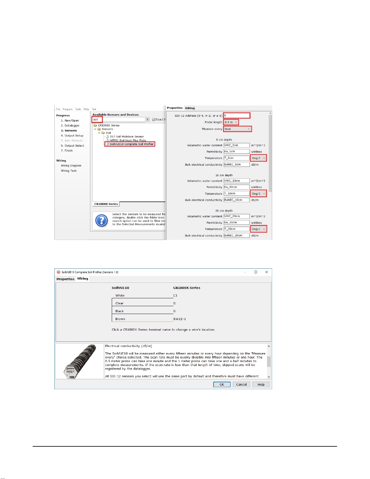
3. In the Available Sensors and Devices box, type SoilVUE10 or locate the probe in the
Sensors> Soil folder. Double-click SoilVUE10 Complete Soil Profiler. Type the correct
SDI-12 Address; default address is 0. The Probe length defaults to 0.5 m. This is changed by
clicking the Probe length box and selecting 1 m. Select whether to Measure every hour
(default) or every fifteen minutes. For each measurement depth, temperature defaults to
degrees Celsius. This can be changed by clicking the Deg C box and selecting Deg F, for
degrees Fahrenheit, or K for Kelvin.
4. Click the Wiring tab to see how the probe is to be wired to the data logger. Click OK after
wiring the probe.
5. Repeat steps three and four for other sensors.
SoilVUE™10 Complete Soil Profiler 3
Page 9
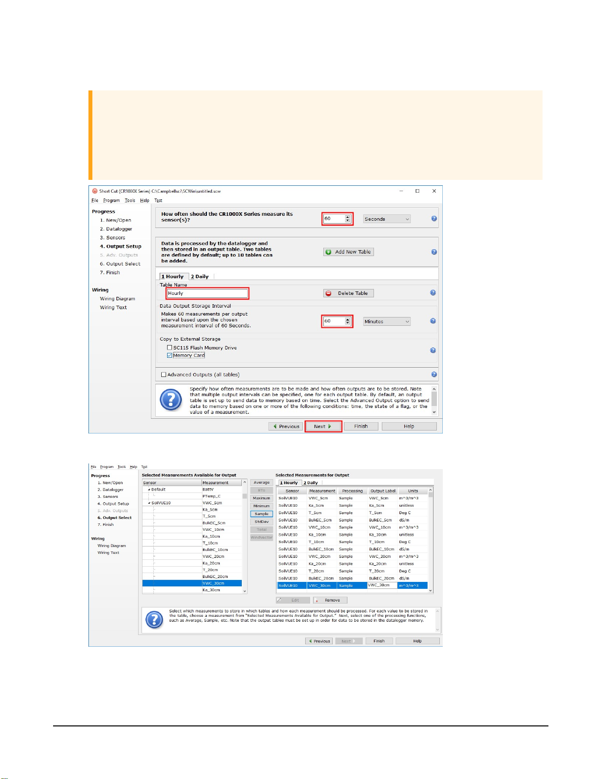
6. In Output Setup, type the scan rate, meaningful table names, and Data Output Storage
Interval.
CAUTION:
The scan rate must be evenly divisible into fifteen minutes or one hour (depending on
the Measure every selected in step 3). The 0.5m probe can take one minute, and the
1m probe can take one and a half minutes to complete measurements. If the scan rate
is less than that length of time, skipped scans will be registered by the data logger.
7. Select the measurement and its associated output option.
SoilVUE™10 Complete Soil Profiler 4
Page 10
8. Click Finish and save the program. Send the program to the data logger if the data logger
is connected to the computer.
9. If the sensor is connected to the data logger, check the output of the sensor in the data
display in LoggerNet, RTDAQ, or PC400 to make sure it is making reasonable
measurements.
5. Overview
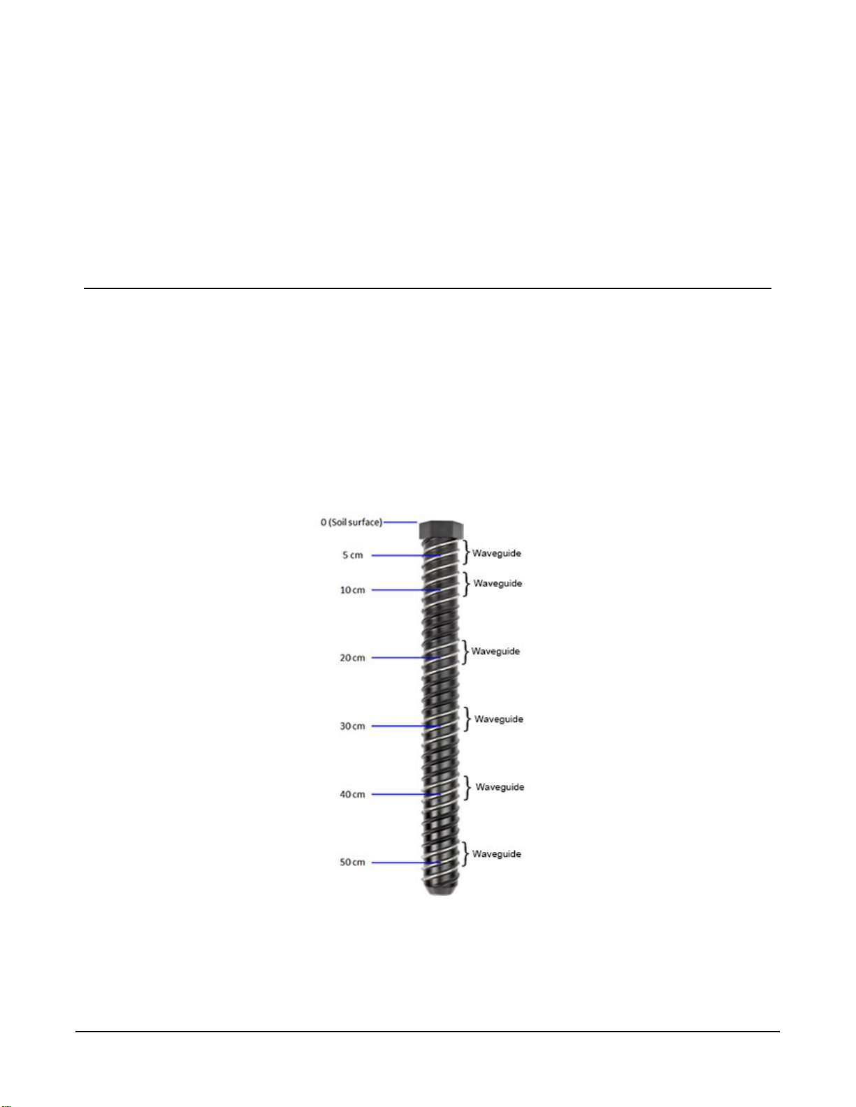
The SoilVUE 10 uses time-domain reflectometry (TDR) to measure soil volumetric water content
(VWC) and electrical conductivity (EC). The waveguides (measurement rods) are embedded in
threads and centred on the measurement depths of 5, 10, 20, 30, 40, and 50 cm for the 0.5 m
option (FIGURE 5-1 (p. 5)) and 60, 75, and 100 cm are added on for the 1 m option. The threaded
design maximizes soil contact and minimizes preferential flow—two major drawbacks to
smooth-sided soil profiling probes. Campbell Scientific’s proprietary implementation of TDR
produces a clean, high resolution measurement that provides accuracy and assurance that
cannot be found among other commercially available sensors.
FIGURE 5-1. SoilVUE 10 waveguides and measurement depths
SoilVUE™10 Complete Soil Profiler 5
Page 11

The SoilVUE 10 should be installed in a hole made by a standard 5-cm (2-inch) hand auger tool.
Auger the hole to the proper depth and screw the SoilVUE 10 into the hole (Field installation (p.
9)). Water should be used to lubricate the sides of the hole to aid in installation and to ensure
the probe is not damaged due to excessive force. The threaded design presses the sensing
elements into the side of the hole, producing optimal contact with the soil and minimizing air
gaps that are common with alternative profile probes.
The SoilVUE 10 also has a detachable cable that allows either the probe or cable to be
independently replaced if it gets damaged.
All of these design factors combine to result in a more accurate measurement.
Features:
l Volumetric water content (VWC), electrical conductivity (EC), permittivity, and temperature
measurements at six depths over 0.5 m or 9 depths over 1.0 m using one probe
l Campbell Scientific proprietary TrueWave™ TDR technology uses advanced waveform
analysis to determine the true travel time of a high frequency pulse that provides
defensible measurements that can be universally compared with other TDR systems
l Threaded design with individual waveguides built into the threads for optimal contact with
soil, which minimizes air-gap errors
l Installation using a standard 5-cm (2-inch) hand auger eliminating the need for excavation
machinery or expensive proprietary tools
l Quick and low impact installation
l Detachable cable that facilitates field replacement
l SDI-12 digital output
l Designed for long-term outdoor operation
l Compatible CRBasic data loggers: CR6, CR3000, CR1000X, CR800-series, CR300-series,
CR1000
6. Specifications
Operating temperature range:
Volumetric water content range:
Maximuminstallationtorque:
Diameterwithoutthreads:
Diameter including threads:
Length
: 0.55 m/1.05 m (21.5 in/41.2 in)
–40 to 60 °C
0 to 100%
54 N•m (40 ft•lb)
5.2 cm (2.05 in)
5.8 cm (2.3 in)
SoilVUE™10 Complete Soil Profiler 6
Page 12

Weight
: 1.9 kg/3.6 kg (4.2 lb/7.9 lb)
Output:
Operating voltage:
Current drain at 12 VDC:
Measurement depths
0.5 m option:
1 m option:
Permittivity range:
Electricalconductivityrange:
Accuracy
Volumetricwatercontent:
SDI-12 Version 1.4 compliant
9 to 36 VDC
~1.5 mA (quiescent), ~64 mA (active)
5, 10, 20, 30, 40, and 50 cm (2, 4, 8, 12, 16, 20 inch)
5, 10, 20, 30, 40, 50, 60, 75, and 100 cm (2, 4, 8, 12, 16, 20, 24,
30, and 40 inch)
1 to 80
0 to 10 dS/m
±1.5% typical with most soils; soils with high organic matter
(>12% soil organic carbon) or high clay content (>45% clay)
may need a soil specific calibration due to the dispersive
nature of these materials. For more information, refer to
specific calibration procedure for volumetric water content
Soil-
available on our website.
www.campbellsci.eu/soilvue10
Permittivity:
Electrical Conductivity:
Temperature:
Response time:
Compliance documents:
sensors
±1 permittivity unit between 4 and 42 permittivity
±2% (0 to 2.5 dS/m), ±5% (full range)
± 0.15 °C between –30 and 40 °C
Up to 1 minute for 0.5 m probe and up to 1.5 minutes for 1 m
probe
View at:
7. Installation
If you are programming your data logger with Short Cut, skip Wiring (p. 8) and SDI-12
programming (p. 8). Short Cut does this work for you. See QuickStart (p. 2) for a tutorial.
SoilVUE™10 Complete Soil Profiler 7
Page 13

7.1 Wiring
Table 7-1 (p. 8) provides the connections for the SoilVUE 10.
Table 7-1: Wire colour, function, and data logger connection
Wire colour Wire function Data logger connection
White SDI-12 signal C, SDI-12, or U configured for SDI-12
Clear Shield ⏚ (analogue ground)
Brown Power 12V
Black Power ground G
1
U and C terminals are automatically configured by the measurement instruction.
For the CR6 and CR1000X data loggers, triggering conflicts may occur when a companion
terminal is used for a triggering instruction such as TimerInput(), PulseCount(), or
WaitDigTrig(). For example, if the SoilVUE 10 is connected to C3 on a CR1000X, C4 cannot
be used in the TimerInput(), PulseCount(), or WaitDigTrig() instructions.
1
7.2 SDI-12 programming
This instruction sends a request to the sensor to make a measurement and then retrieves the
measurement from the sensor. See SDI-12 measurements (p. 12) for more information.
For most data loggers, the SDI12Recorder() instruction has the following syntax:
SDI12Recorder(Destination, SDIPort, SDIAddress, “SDICommand”, Multiplier,
Offset, FillNAN, WaitonTimeout)
For the SDIAddress, alphabetical characters need to be enclosed in quotes (for example,
“A”). Also enclose the SDICommandin quotes as shown. The Destinationparameter must
be an array. The required number of values in the array depends on the command (see Table 8-1
(p. 13)).
FillNANand WaitonTimeoutare optional parameters (refer to CRBasic Help for more
information).
A downloadable example program is available at www.campbellsci.eu/downloads/soilvue10-
example-program .
SoilVUE™10 Complete Soil Profiler 8
Page 14

7.3 Siting
For more information on installation, watch a video at www.campbellsci.eu/videos/soilvue10 .
Proper installation of the SoilVUE 10 is critical. This includes selecting a monitoring site that is
representative of the soil of interest, ensuring good contact between the waveguides and the
surrounding soil, minimizing disturbance to the soil, and minimizing preferential flow of water
along the probe.
Factors that affect the distribution of water in soil include soil properties such as texture, depth,
and compaction, slope, land usage, vegetation, and disturbance history.
The selected site should be representative of the soil of interest. Certain soil types may present a
challenge to properly installing the probe. For instance, sandy soil types are likely to collapse into
the augered hole. Pre-wetting the installation location may help in firming up the soil and allow
a hole to be created.
Rocky soils may prevent an auger from creating a hole deep enough for the probe or may
damage the probe during the installation process. Minor abrasions and dents to the body or
threads should not influence the measurements. However, rocky soils may require a different
approach to the installation. Either create a larger hole and use a slurry method to install the
probe, or excavate the soil then back fill the soil around the probe.
7.4 Field installation
Campbell Scientific offers a SoilVUE 10 Installation Kit (FIGURE 7-1 (p. 9)).
FIGURE 7-1. Components of the installation kit
A – Auger extension shaft
B – Hex socket
C – Hex socket handle
D – Edelman auger
E – Auger clean-out tool
F – Rods to aid in disassembly (insert through holes in extension shaft)
G – T-handle for auger/extension shaft
SoilVUE™10 Complete Soil Profiler 9
Page 15

The installation kit is not necessary to install the SoilVUE 10. A standard 5cm (2-inch) hand auger
may be used instead of the auger supplied in the kit. The SoilVUE 10 can then be inserted into
the hole using a standard six-sided 2.25-inch socket.
CAUTION:
Do not use a power auger since they may enlarge the hole diameter beyond the desired
specification for a properly installed probe. Power augers also tend to bring soil up from
lower depths, coating the sides of the hole, which may have adverse effects on the
measurements.
1. Connect the T-handle (FIGURE 7-1 (p. 9), G) to the auger extension shaft (FIGURE 7-1 (p. 9),
A) then connect the shaft to the auger (FIGURE 7-1 (p. 9), D).
2. Use the auger assembly to create a hole with a 5cm (2inch) diameter that is approximately
5cm (2inch) deeper than the SoilVUE 10 length. The auger is narrow at the tip, so making
the hole 5cm (2inch) deeper will ensure the sensor can be fully installed.
CAUTION:
Large gaps between the SoilVUE 10 and the hole bottom can adversely affect the
measurements. The following auger depths allow proper installation, while avoiding
large gaps.
a. Care should be taken to ensure the sides of the hole are even and do not become
tapered with repeated removal of soil.
b. Wet the sides of the hole to reduce the force needed to install the probe. In most
cases, the hole will need to be thoroughly wetted.
SoilVUE™10 Complete Soil Profiler 10
Page 16

CAUTION:
When adding water to the hole, avoid eroding the sides, introducing air gaps. Also
avoid having standing water at the bottom of the hole.
3. Insert the hex socket handle into the small holes in the hex socket (FIGURE 7-2 (p. 11)).
FIGURE 7-2. Hex socket handle and hex socket
CAUTION:
Leave the plastic cap on the cable connection until the sensor is completely installed
and ready to connect the cable.
4. Place the hex socket on top of the probe and use the handle to screw the probe into the
augered hole.
CAUTION:
Applying too much force to the sensor during installation can break or crack it. The
maximum torque applied during installation should not exceed 54N•m (40ft•lb). If it is
taking significant effort to install, make the hole slightly deeper, add more water, create
another hole, or try a combination of these options.
SoilVUE™10 Complete Soil Profiler 11
Page 17

a. When the probe is partially installed, remove 5cm (2inch) of soil from the top of the
hole. This will prevent the connector from digging into the soil as the probe is
installed, and provide room for connecting the cable.
b. To ensure good contact, carefully replace the soil while adding water and packing
well. When the top of the probe is flush with the soil surface, the top sensor is at
5cm (2inch) depth.
5. Connect the cable to the SoilVUE 10, and hand tighten the cable connector nut to ensure a
water-tight seal. Do not over tighten. The cable nut should turn easily. If it does not, check
to make sure it is correctly aligned. Also, try gently pushing in on the cable.
WARNING:
Do not over tighten. Never use a wrench or spanner on the cable connector nut
because it will damage the connector.
6. Route the cable to the data logger.
8. Operation
8.1 SDI-12 measurements
The SoilVUE 10 responds to the SDI-12 commands shown in Table 8-1 (p. 13). Because of the
delays the M! command requires, Campbell Scientific recommends measurement scans of at least
10 seconds per sensor. For instance, the recommended scan rate for a 0.5 m probe with six
sensors is at least 60 seconds. A C! command does not require the data logger to pause its
operation until the values are ready.
SoilVUE™10 Complete Soil Profiler 12
Page 18

Table 8-1: SoilVUE 10 SDI-12 commands
SDI-12 command
(a is the SDI-12 address)
aM!
aM1! or aC1!
Values returned or function Units
1. Volumetric Water Content, 5 cm
2. Volumetric Water Content, 10 cm
3. Volumetric Water Content, 20 cm
4. Volumetric Water Content, 30 cm
5. Volumetric Water Content, 40 cm
6. Volumetric Water Content, 50 cm
7. Volumetric Water Content, 60 cm
8. Volumetric Water Content, 75 cm
9. Volumetric Water Content, 100 cm
1. Volumetric Water Content, 5 cm
2. Relative Permittivity, ɛ, 5 cm
3. Temperature, 5 cm
4. Bulk Electrical Conductivity, 5 cm
3
m3/m
3
m3/m
3
m3/m
3
m3/m
3
m3/m
3
m3/m
1
1
1
m3/m
m3/m
m3/m
m3/m
3
3
3
3
°C
dS/m
aM2! or aC2!
aM3! or aC3!
aM4! or aC4!
aM5! or aC5!
1. Volumetric Water Content, 10 cm
2. Relative Permittivity, ɛ, 10 cm
3. Temperature, 10 cm
4. Bulk Electrical Conductivity, 10 cm
1. Volumetric Water Content, 20 cm
2. Relative Permittivity, ɛ, 20 cm
3. Temperature, 20 cm
4. Bulk Electrical Conductivity, 20 cm
1. Volumetric Water Content, 30 cm
2. Relative Permittivity, ɛ, 30 cm
3. Temperature, 30 cm
4. Bulk Electrical Conductivity, 30 cm
1. Volumetric Water Content, 40 cm
2. Relative Permittivity, ɛ, 40 cm
3. Temperature, 40 cm
m3/m
°C
dS/m
m3/m
°C
dS/m
m3/m
°C
dS/m
m3/m
°C
3
3
3
3
4. Bulk Electrical Conductivity, 40 cm
SoilVUE™10 Complete Soil Profiler 13
dS/m
Page 19
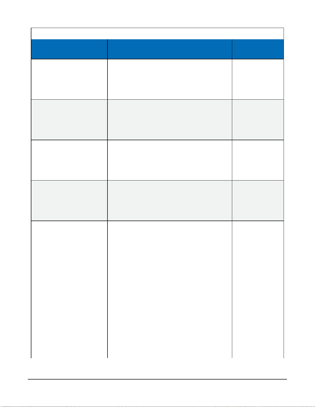
Table 8-1: SoilVUE 10 SDI-12 commands
SDI-12 command
(a is the SDI-12 address)
aM6! or aC6!
aM7! or aC7!
aM8! or aC8!
1
1
Values returned or function Units
1. Volumetric Water Content, 50 cm
2. Relative Permittivity, ɛ, 50 cm
3. Temperature, 50 cm
4. Bulk Electrical Conductivity, 50 cm
1. Volumetric Water Content, 60 cm
2. Relative Permittivity, ɛ, 60 cm
3. Temperature, 60 cm
4. Bulk Electrical Conductivity, 60 cm
1. Volumetric Water Content, 75 cm
2. Relative Permittivity, ɛ, 75 cm
3. Temperature, 75 cm
4. Bulk Electrical Conductivity, 75 cm
1. Volumetric Water Content, 100 cm
m3/m
°C
dS/m
m3/m
°C
dS/m
m3/m
°C
dS/m
m3/m
3
3
3
3
aM9! or aC9!
aC!
1
2. Relative Permittivity, ɛ, 100 cm
3. Temperature, 100 cm
4. Bulk Electrical Conductivity, 100 cm
1. Volumetric Water Content, 5 cm
°C
dS/m
m3/m
3
2. Relative Permittivity, ɛ, 5 cm
3. Temperature, 5 cm
4. Bulk Electrical Conductivity, 5 cm
5. Volumetric Water Content, 10 cm
°C
dS/m
m3/m
3
6. Relative Permittivity, ɛ, 10 cm
7. Temperature, 10 cm
8. Bulk Electrical Conductivity, 10 cm
9. Volumetric Water Content, 20 cm
°C
dS/m
m3/m
3
10. Relative Permittivity, ɛ, 20 cm
11. Temperature, 20 cm
12. Bulk Electrical Conductivity, 20 cm
13. Volumetric Water Content, 30 cm
°C
dS/m
m3/m
3
14. Relative Permittivity, ɛ, 30 cm
SoilVUE™10 Complete Soil Profiler 14
Page 20
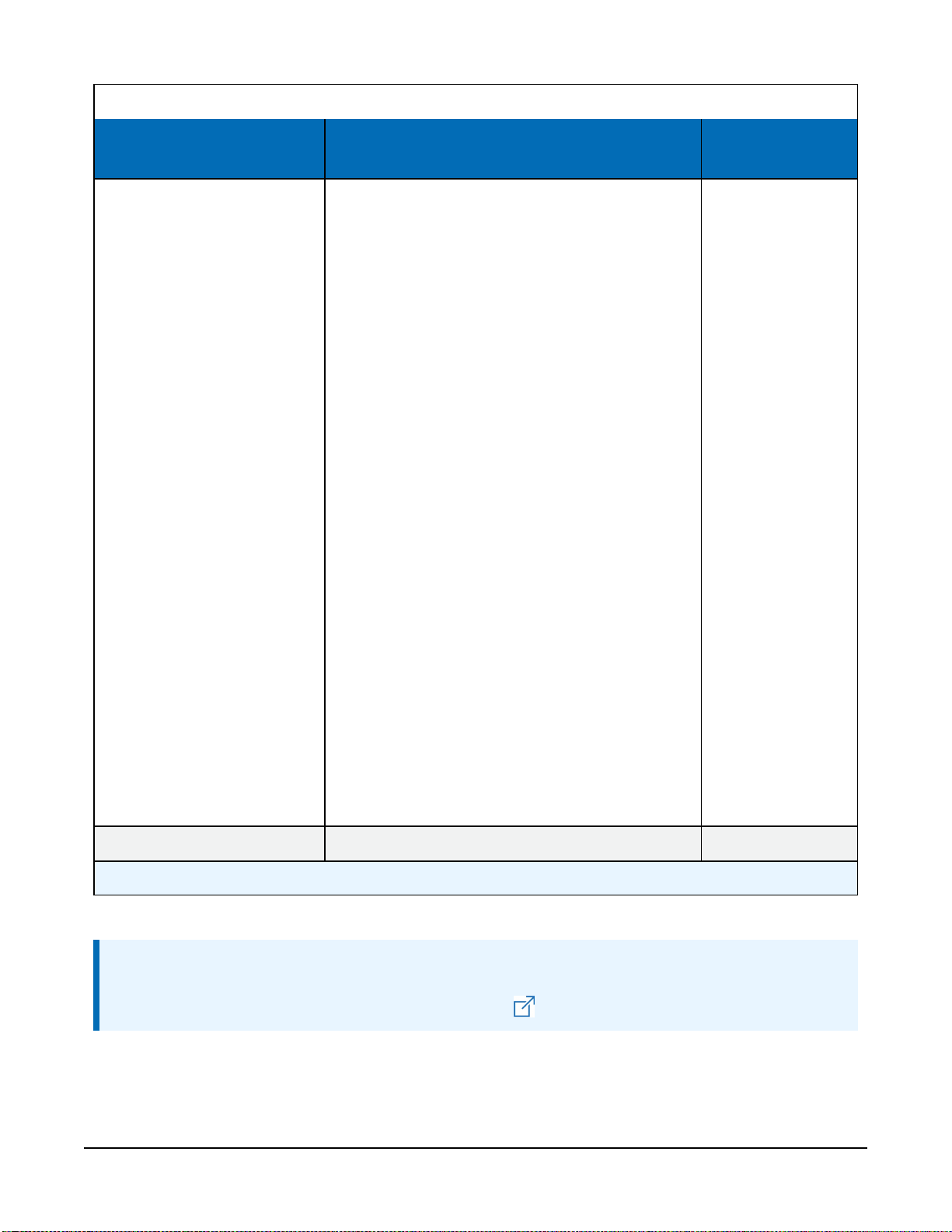
Table 8-1: SoilVUE 10 SDI-12 commands
SDI-12 command
(a is the SDI-12 address)
Values returned or function Units
15. Temperature, 30 cm
16. Bulk Electrical Conductivity, 30 cm
17. Volumetric Water Content, 40 cm
18. Relative Permittivity, ɛ, 40 cm
19. Temperature, 40 cm
20. Bulk Electrical Conductivity, 40 cm
21. Volumetric Water Content, 50 cm
22. Relative Permittivity, ɛ, 50 cm
23. Temperature, 50 cm
24. Bulk Electrical Conductivity, 50 cm
25. Volumetric Water Content, 60 cm
26. Relative Permittivity, ɛ, 60 cm
27. Temperature, 60 cm
1
1
28. Bulk Electrical Conductivity, 60 cm
29. Volumetric Water Content, 75 cm
30. Relative Permittivity, ɛ, 75 cm
31. Temperature, 75 cm
1
1
1
32. Bulk Electrical Conductivity, 75 cm
33. Volumetric Water Content, 100 cm
34. Relative Permittivity, ɛ, 100 cm
35. Temperature, 100 cm
1
1
36. Bulk Electrical Conductivity, 100 cm
°C
dS/m
3
m3/m
°C
dS/m
3
m3/m
°C
dS/m
3
m3/m
°C
1
dS/m
m3/m
3
°C
1
1
dS/m
m3/m
3
°C
1
dS/m
?!
1
One meter probe only.
Returns the SDI-12 Address
NOTE:
SDI-12 sensor support (p. 19) describes the SDI-12 commands. Additional SDI-12 information
is available in SDI-12 Support, or at www.sdi-12.org .
SoilVUE™10 Complete Soil Profiler 15
Page 21
8.2 Measurements at fast scan rates
Using the SlowSequence function allows the SDI-12 instruction to run as a background
process, causing minimum interference to other measurements that use the analogue hardware.
Measuring the SoilVUE 10 in a SlowSequencesection of the program allows faster programs
to run as the main scan. However, if the data logger is too busy to complete all of its tasks, some
slow sequence commands may be skipped resulting in NANs (not a number) instead of
measurements.
8.3 Measurement theory
The SoilVUE 10 is a multiparameter soil profile probe that measures soil volumetric water content
using a time-domain reflectometry (TDR) method. The probe consists of TDR circuitry connected
to a series of six or nine helical waveguides that makeup part of the overall threaded design.
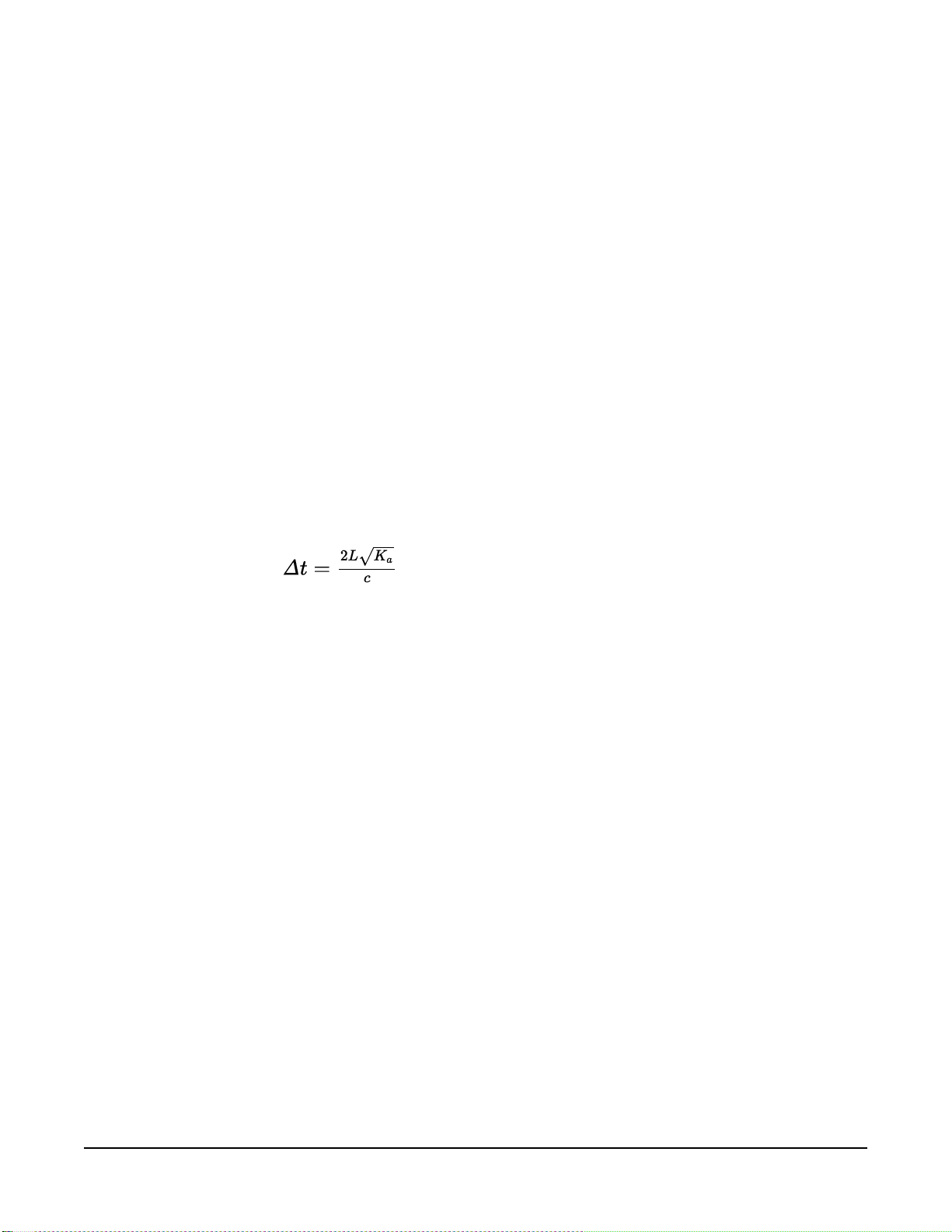
The travel time for a pulsed electromagnetic signal along a waveguide is dependent on the
velocity of the signal and the waveguide length. The velocity is dependent on the dielectric
constant of the material surrounding the waveguide. This relationship can be expressed by:
Eq. 1
Where,
Kais the apparent permittivity
c is the velocity of electromagnetic signals in free space
Δt is the travel time
L is the waveguide length
Eq. 1 (p. 16) can be simplified to express the apparent permittivity as the ratio of the apparent
probe length (La= c•Δt/2) to the real probe length.
Ka= (La/L)
The permittivity of water relative to other soil constituents is high. Consequently, changes in
volumetric water content can be directly related to the change in the permittivity of bulk soil
material. The relationship between permittivity and volumetric water content has been described
by, among others, Topp et al. (1980) and Ledieu et al. (1986) in an empirical fashion using both
polynomial and linear forms.
2
Eq. 2
SoilVUE™10 Complete Soil Profiler 16
Page 22

9. Maintenance and troubleshooting
NOTE:
All factory repairs and recalibrations require a returned material authorization (RMA) and
completion of the “Statement of Product Cleanliness and Decontamination” form. Refer to
the Assistance page at the front of this manual for more information.
The SoilVUE 10 does not require periodic maintenance. For troubleshooting, Table 9-1 (p. 17)
provides symptoms, possible causes, and solutions.
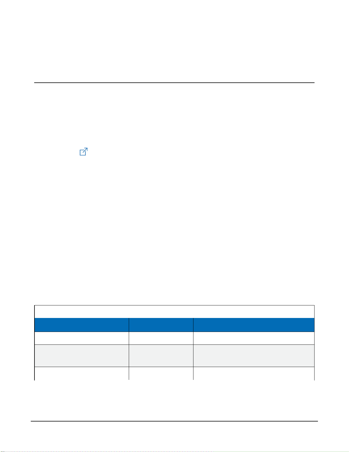
Table 9-1: Symptoms, possible causes, and solutions
Symptom Possible cause Solution
SoilVUE 10
All
output values
read 0
First value reads
NAN and all other
values read 0 or
never change
from one
measurement to
another.
Readings erratic,
including NANs
and 9999999s
No SDI12Recorder() instruction
in data logger program.
Conditional statement that triggers
reading is not evaluating as true
SoilVUE 10 SDI-12 address does not
match address specified in data
logger program
SoilVUE 10 is not connected to the
SDI-12 terminal specified in data
logger program
SoilVUE 10 not being powered
Multiple devices with same SDI-12
address sharing sameUorCterminal
Add SDI12Recorder()
instruction to data logger program
Check logic of conditional statement
that triggers readings
Change SoilVUE 10 SDI-12 address or
modify program so that they match
Connect wire to correct terminal or
modify program to match wiring
Make sure the SoilVUE 10 is wired
correctly and that it matches the data
logger program
Connect each SDI-12 device to a
differentUorCterminal or give
them unique SDI-12 addresses.
Ensure that you revise the data
logger program to account for these
changes.
SoilVUE™10 Complete Soil Profiler 17
Page 23

Appendix A. Importing Short
Cut code into CRBasic Editor
Short Cut creates a .DEF file that contains wiring information and a program file that can be
imported into the CRBasic Editor. By default, these files reside in the C:\campbellsci\SCWin
folder.
Import Short Cut program file and wiring information into CRBasic Editor:
1. Create the Short Cut program. After saving the Short Cut program, click the Advanced tab
then the CRBasic Editor button. A program file with a generic name will open in CRBasic.
Provide a meaningful name and save the CRBasic program. This program can now be
edited for additional refinement.
NOTE:
Once the file is edited with CRBasic Editor, Short Cut can no longer be used to edit the
program it created.
2. To add the Short Cut wiring information into the new CRBasic program, open the .DEF file
located in the C:\campbellsci\SCWin folder, and copy the wiring information, which is at
the beginning of the .DEF file.
3. Go into the CRBasic program and paste the wiring information into it.
4. In the CRBasic program, highlight the wiring information, right-click, and select Comment
Block. This adds an apostrophe (') to the beginning of each of the highlighted lines, which
instructs the data logger compiler to ignore those lines when compiling. The Comment
Block feature is demonstrated at about 5:10 in the CRBasic | Features video .
SoilVUE™10 Complete Soil Profiler 18
Page 24
Appendix B. SDI-12 sensor support
SDI-12, Serial Data Interface at 1200 baud, is a protocol developed to simplify sensor and data
logger compatibility. Only three wires are necessary — serial data, ground, and 12 V. With unique
addresses, multiple SDI-12 sensors can connect to a single SDI-12 terminal on a Campbell
Scientific data logger.
This appendix discusses the structure of SDI-12 commands and the process of querying SDI-12
sensors. For more detailed information, refer to version 1.4 of the SDI-12 protocol, available at
www.sdi-12.org .
For additional information, refer to the SDI-12 Sensors | Transparent Mode and SDI-12 Sensors |
Watch or Sniffer Mode videos.
B.1 SDI-12 command basics
SDI-12 commands have three components:
l Sensor address (a) – a single character and the first character of the command. Use the
default address of zero (0) unless multiple sensors are connected to the same port.
l Command body – an upper case letter (the “command”), optionally followed by one or
more alphanumeric qualifiers.
l Command termination (!) – an exclamation mark.
An active sensor responds to each command. Responses have several standard forms and always
terminate with <CR><LF> (carriage return and line feed). Standard SDI-12 commands are listed
in Table B-1 (p. 19).
Table B-1: Campbell Scientific sensor SDI-12 command and response set
Name Command
Acknowledge Active
Send Identification
Start Verification
a!
aI!
aV!
Response
a<CR><LF>
allccccccccmmmmmmvvvxxx...xx
<CR><LF>
atttn <CR><LF>
1
SoilVUE™10 Complete Soil Profiler 19
Page 25

Table B-1: Campbell Scientific sensor SDI-12 command and response set
Name Command
Address Query
Change Address
Start Measurement
Start Measurement
and Request CRC
Start Concurrent Measurement
StartConcurrentMeasurement
and Request CRC
Send Data
Continuous Measurement
?!
aAb!
aM!
aM1!...aM9!
aMC!
aMC1!...aMC9!
aC!
aC1!...aC9!
aCC!
aCC1!...aCC9!
aD0!...aD9!
aR0!...aR9!
Response
a<CR><LF>
b<CR><LF>
atttn<CR><LF>
atttn <CR><LF>
atttnn<CR><LF>
atttnn<CR><LF>
a<values><CR><LF> or
a<values><CRC><CR><LF>
a<values><CR><LF>
1
Continuous Measurement
and Request CRC
Extended Commands
1
Information on each of these commands is given in the following sections.
aRC0!...aRC9!
aXNNN!
a<values><CRC><CR><LF>
a<values><CR><LF>
B.2 Acknowledge active command (a!)
The Acknowledge Active command (a!) is used to test a sensor on the SDI-12 bus. An active
sensor responds with its address.
B.3 Send identification command (al!)
Sensor identifiers are requested by issuing command aI!. The reply is defined by the sensor
manufacturer but usually includes the sensor address, SDI-12 version, manufacturer’s name, and
sensor model information. Serial number or other sensor specific information may also be
included.
aI!
allccccccccmmmmmmvvvxxx...xx<CR><LF>
a Sensor SDI-12 address
SoilVUE™10 Complete Soil Profiler 20
Page 26

ll SDI-12 version number (indicates compatibility)
cccccccc 8-character vendor identification
mmmmmm 6 characters specifying the sensor model
vvv 3 characters specifying the sensor version (operating system)
xxx…xx
<CR><LF>
Source: SDI-12: A Serial-Digital Interface Standard for Microprocessor-Based Sensors (see References).
Up to 13 optional characters used for a serial number or other specific
sensor information that is not relevant for operation of the data logger
Terminates the response
B.4 Start verification command (aV!)
The response to a Start Verification command can include hardware diagnostics, but like the aI!
command, the response is not standardized.
Command: aV!
Response: atttn<CR><LF>
a = sensor address
ttt = time, in seconds, until verification information is available
n = the number of values to be returned when one or more subsequent D! commands are issued
B.5 Address query command (?!)
Command ?! requests the address of the connected sensor. The sensor replies to the query with
the address, a. This command should only be used with one sensor on the SDI-12 bus at a time.
B.6 Change address command (aAb!)
Multiple SDI-12 sensors can connect to a single SDI-12 terminal on a data logger. Each device on
a single terminal must have a unique address.
A sensor address is changed with command aAb!, where a is the current address and b is the
new address. For example, to change an address from 0 to 2, the command is 0A2!. The sensor
responds with the new address b, which in this case is 2.
SoilVUE™10 Complete Soil Profiler 21
Page 27

NOTE:
Only one sensor should be connected to a particular terminal at a time when changing
addresses.
B.7 Start measurement commands (aM!)
A measurement is initiated with the M! command. The response to each command has the form
atttn<CR><LF>, where
a = sensor address
ttt = time, in seconds, until measurement data is available. When the data is ready, the sensor
notifies the data logger, and the data logger begins issuing D commands.
n = the number of values returned when one or more subsequent D commands are issued. For
the aM! command, n is an integer from 0 to 9.
When the aM! is issued, the data logger pauses its operation and waits until either it receives the
data from the sensor or the time, ttt, expires. Depending on the scan interval of the data logger
program and the response time of the sensor, this may cause skipped scans to occur. In this case
make sure your scan interval is longer than the longest measurement time (ttt).
Table B-2: Example aM! sequence
0M!
00352<CR><LF>
0<CR><LF>
0D0!
0+.859+3.54<CR><LF>
The data logger makes a request to sensor 0 to start a measurement.
Sensor 0 immediately indicates that it will return two values within
the next 35 seconds.
Within 35 seconds, sensor 0 indicates that it has completed the
measurement by sending a service request to the data logger.
The data logger immediately issues the first D command to collect
data from the sensor.
The sensor immediately responds with the sensor address and the two
values.
B.8 Stopping a measurement command
A measurement command (M!) is stopped if it detects a break signal before the measurement is
complete. A break signal is sent by the data logger before most commands.
A concurrent measurement command (C!) is aborted when another valid command is sent to the
sensor before the measurement time has elapsed.
SoilVUE™10 Complete Soil Profiler 22
Page 28

B.9 Send data command (aD0! … aD9!)
The Send Data command requests data from the sensor. It is issued automatically with every type
of measurement command (aM!, aMC!, aC!, aCC!). When the measurement command is aM!
or aMC!, the data logger issues the aD0! command once a service request has been received
from the sensor or the reported time has expired. When the data logger is issuing concurrent
commands (aC! or aCC!), the Send Data command is issued after the required time has elapsed
(no service request will be sent by the sensor). In transparent mode (see SDI-12 transparent mode
(p. 23) ), the user asserts this command to obtain data.
Depending on the type of data returned and the number of values a sensor returns, the data
logger may need to issue aD0! up to aD9! to retrieve all data. A sensor may return up to 35
characters of data in response to a D command that follows an M! or MC! command. A sensor
may return up to 75 characters of data in response to a D command that follows a C! or CC!
command. Data values are separated by plus or minus signs.
Command: aD0! (aD1! … aD9!)
Response: a<values><CR><LF> or a<values><CRC><CR><LF>
where:
a = the sensor address
<values> = values returned with a polarity sign (+ or –)
<CR><LF> = terminates the response
<CRC> = 16-bit CRC code appended if data was requested with aMC! or aCC!.
B.10 SDI-12 transparent mode
System operators can manually interrogate and enter settings in probes using transparent mode.
Transparent mode is useful in troubleshooting SDI-12 systems because it allows direct
communication with probes. Data logger security may need to be unlocked before activating the
transparent mode.
Transparent mode is entered while the computer is communicating with the data logger through
a terminal emulator program. It is accessed through Campbell Scientific data logger support
software or other terminal emulator programs. Data logger keyboards and displays cannot be
used.
The terminal emulator is accessed by navigating to the Tools list in PC400 or the Datalogger list
in the Connect screen of LoggerNet.
SoilVUE™10 Complete Soil Profiler 23
Page 29

Watch the video: SDI-12 Sensors | Transparent Mode.
Data loggers from other manufacturers will also have a transparent mode. Refer to those manuals
on how to use their transparent mode.
The following examples show how to enter transparent mode and change the SDI-12 address of
an SDI-12 sensor. The steps shown in Changing an SDI-12 address (p. 24) are used with most
Campbell Scientific data loggers.
B.10.1 Changing an SDI-12 address
This example was done with a CR1000X, but the steps are only slightly different for CR6, CR3000,
CR800-series, CR300-series, CR1000 data loggers.
1. Connect an SDI-12 sensor to the CR1000X.
2. In LoggerNet Connect, under Datalogger, click Terminal Emulator. The terminal emulator
window opens.
3. Under Select Device, located in the lower left side of the window, select the CR1000X
4. Click Open Terminal.
5. Select All Caps Mode.
6. Press Enter until the data logger responds with the CR1000X> prompt.
7. Type SDI12 and press Enter.
SoilVUE™10 Complete Soil Profiler 24
Page 30

8. At the Select SDI12 Port prompt, type the number corresponding to the control port where
the sensor is connected and press Enter. The response Entering SDI12 Terminal indicates
that the sensor is ready to accept SDI-12 commands.
9. To query the sensor for its current SDI-12 address, type ?! and press Enter. The sensor
responds with its SDI-12 address. If no characters are typed within 60 seconds, the mode is
exited. In that case, simply type SDI12 again, press Enter, and type the correct control port
number when prompted.
10. To change the SDI-12 address, type aAb!, where a is the current address from the previous
step and b is the new address. Press Enter. The sensor changes its address and responds
with the new address. In the following example, the sensor address is changed from 0 to B.
11. To exit SDI-12 transparent mode, click Close Terminal.
NOTE:
The transparent mode for the CR6, CR3000, CR800-series, CR300-series, and CR1000 data
loggers is similar to that shown for the CR1000X.
SoilVUE™10 Complete Soil Profiler 25
Page 31

Campbell Scientific regional offices
Australia
Location:
Phone:
Email:
Website:
Brazil
Location:
Phone:
Email:
Website:
Canada
Location:
Phone:
Email:
Website:
China
Location:
Phone:
Email:
Website:
Garbutt, QLD Australia
61.7.4401.7700
info@campbellsci.com.au
www.campbellsci.com.au
São Paulo, SP Brazil
11.3732.3399
vendas@campbellsci.com.br
www.campbellsci.com.br
Edmonton, AB Canada
780.454.2505
dataloggers@campbellsci.ca
www.campbellsci.ca
Beijing, P. R. China
86.10.6561.0080
info@campbellsci.com.cn
www.campbellsci.com.cn
France
Location:
Phone:
Email:
Website:
Germany
Location:
Phone:
Email:
Website:
India
Location:
Phone:
Email:
Website:
South Africa
Location:
Phone:
Email:
Website:
Vincennes, France
0033.0.1.56.45.15.20
info@campbellsci.fr
www.campbellsci.fr
Bremen, Germany
49.0.421.460974.0
info@campbellsci.de
www.campbellsci.de
New Delhi, DL India
91.11.46500481.482
info@campbellsci.in
www.campbellsci.in
Stellenbosch, South Africa
27.21.8809960
sales@campbellsci.co.za
www.campbellsci.co.za
Thailand
Location:
Phone:
Email:
Website:
UK
Location:
Phone:
Email:
Website:
USA
Location:
Phone:
Email:
Website:
Bangkok, Thailand
66.2.719.3399
info@campbellsci.asia
www.campbellsci.asia
Shepshed, Loughborough,
UK
44.0.1509.601141
sales@campbellsci.co.uk
www.campbellsci.co.uk
Logan, UT USA
435.227.9120
info@campbellsci.com
www.campbellsci.com
Costa Rica
Location:
Phone:
Email:
Website:
San Pedro, Costa Rica
506.2280.1564
info@campbellsci.cc
www.campbellsci.cc
Spain
Location:
Phone:
Email:
Website:
Barcelona, Spain
34.93.2323938
info@campbellsci.es
www.campbellsci.es
 Loading...