

Page 1
Revision:01/2021
Copyright © 2019 – 2021
Campbell Scientific, Inc.
Page 2

Table of contents
1. General information 1
1.1 Packing list 1
1.2 General safety 1
1.3 Sensor unit safety 2
1.4 Laser safety 2
1.5 Electrical safety 4
2. Product overview 5
2.1 Introduction 6
2.1.1 Cloud height detection 6
2.1.2 Sky condition 7
2.1.3 Backscatter profile reporting 7
2.2 Optical measurement 8
2.2.1 Optical arrangement 8
2.3 Internal monitoring 8
2.4 Specifications 9
2.4.1 Measurement specifications 9
2.4.2 Mechanical specifications 9
2.4.3 Electrical specifications 10
2.4.4 Optical specifications 12
2.4.5 Environmental specifications 12
2.4.6 Communications specifications 12
2.4.7 Compliance and testing 13
3. Initial preparation and checks 14
4. Installation 15
4.1 Location and orientation 15
4.2 Grounding 15
4.3 Mounting the SkyVUE 8 16
4.4 Tilt angle 17
4.5 Connectors and wiring 18
4.5.1 Base connectors 18
4.5.2 Wiring using supplied Campbell Scientific cables 19
Table of Contents - i
Page 3

4.5.2.1 Power connections 20
4.5.2.2 Communications connections 21
4.5.3 USB connection 21
4.5.4 I/O connection 22
4.6 Connecting the back-up battery 22
4.7 Bird spike kit 23
4.8 Storage information 24
5. Operation 25
5.1 Terminal mode 25
5.1.1 Entering/exiting the SkyVUE 8 terminal mode 26
5.1.2 Terminal mode commands general 26
5.1.3 Terminal mode command examples 27
5.1.4 Application command message types 41
5.1.5 MCFG command message types 43
5.1.6 Measurement and message intervals 44
5.1.7 Status command 46
5.1.8 Message polling 54
5.1.9 Loading a new operating system (OS) 55
5.1.10 Stratocumulus backscatter calibration 56
5.1.11 CRC-16 codes on terminal commands 58
5.1.12 Service command 58
5.1.13 Locked features 60
5.2 Restoring factory defaults 60
5.3 LED indicator 61
6. Messages 62
6.1 Data messages general 62
6.2 Checksums used in SkyVUE 8 messages 62
6.3 CS messages 63
6.3.1 MESSAGE 001 (no profile, no sky condition) 63
6.3.2 MESSAGE 002 (Profile, no sky condition) 67
6.3.3 MESSAGE 003 (no profile, sky condition) 70
6.3.4 MESSAGE 004 (profile, sky condition) — default message 72
6.4 CL31 messages 76
6.4.1 MESSAGES 101 - 106, (CL31 MESSAGE 1) 76
6.4.2 MESSAGE 005 (no profile, sky condition, mixing layer heights) 77
6.4.3 MESSAGES 107 - 112, CL31 Message 2 81
Table of Contents - ii
Page 4

6.5 CT25K messages 85
6.5.1 MESSAGE 113, CT25K Data Message No. 1 85
6.5.2 MESSAGE 114, CT25K Data Message No. 6 88
7. Maintenance 90
7.1 General 90
7.2 Cleaning 90
7.3 Diagnostic LED indicators within the enclosure 91
7.4 Electrical safety testing 92
Appendix A. Measurement of the attenuated backscatter profile 93
A.1 Initial measurement 93
A.2 Backscatter onset height detection 93
A.3 Produce attenuated backscatter output message 94
Appendix B. Cloud height calculation 95
Appendix C. Sky condition algorithm description 96
Appendix D. Replacing the SkyVUE 8 PSU 98
Appendix E. SkyVUE 8 Laser/APD module replacement 100
List of figures
FIGURE 1-1. Location of laser warning label 4
FIGURE 2-1. Principle of operation 8
FIGURE 2-2. SkyVUE 8 dimensions 10
FIGURE 2-3. PSU types 11
FIGURE 4-1. Mounting base footprint 16
FIGURE 4-2. Setting the tilt angle 17
FIGURE 4-3. Connector layout 18
FIGURE 4-4. Cable connections 21
FIGURE 4-5. USB port 22
FIGURE 4-6. Connecting battery 22
FIGURE 4-7. Ceilometer bird spike kit installed 23
FIGURE 4-8. Preparing the SkyVUE 8 for installing the bird spikes 23
FIGURE 4-9. Attaching bird spikes to the SkyVUE 8 cowl 24
FIGURE 5-1. Restoring factory defaults 61
FIGURE 5-2. LED indicator 61
FIGURE 7-1. Diagnostic LED indicators 92
Table of Contents - iii
Page 5

List of tables
Table 1-1: Packing list 1
Table 4-1: Function of the connector pins for the mains connector 18
Table 4-2: Function of the connector pins for the blower/heater connector 19
Table 4-3: Function of the connector pins for the communications connector 19
Table 5-1: Summary of the terminal mode commands available 28
Table 5-2: Summary of applications and applied settings for SkyVUE 8 42
Table 5-3: Summary of message ID and descriptions 43
Table 6-1: Most significant alarm word for CS messages 64
Table 6-2: Middle alarm word for CS messages 65
Table 6-3: Least significant alarm word for CS messages 66
Table 6-4: Most significant alarm word for CS31 messages 78
Table 6-5: Middle alarm word for CS31 messages 79
Table 6-6: Least significant alarm word for CS31 messages 79
Table 6-7: Most significant alarm word for CT25K messages 86
Table 6-8: Second alarm word for CT25K messages 87
Table of Contents - iv
Page 6
1. General information
1.1 Packing list 1
1.2 General safety 1
1.3 Sensor unit safety 2
1.4 Laser safety 2
1.5 Electrical safety 4
1.1 Packing list
The following table lists the products shipped with the SkyVUE 8.
Table 1-1: Packing list
Description Quantity
Ceilometer 1
Power supply cable 1
Data cable 1
Bolt, sleeve anchor 4
Cable, USB type A plug to type B plug, 2 m 1
Triangle key 1
Calibration plate 1
1.2 General safety
This manual provides important safety considerations for the installation, operation and
maintenance of the SkyVUE™8. These safety considerations are classified into three levels:
WARNING:
Warnings alert the installer or user to serious hazards. Ignoring these warnings could result in
injury or death and/or irrevocable damage to the sensor unit.
SkyVUE™8 (CS136) LIDAR Ceilometer 1
Page 7
CAUTION:
Cautions warn of potential hazards. Ignoring these cautions could result in the sensor being
damaged and data being lost.
NOTE:
Notes highlight useful information in the installation, use and maintenance of this product.
These should be followed carefully in order to gain the maximum benefit from the use of this
product.
1.3 Sensor unit safety
The SkyVUE 8 sensor has been checked for safety before leaving the factory and contains no
internally replaceable or modifiable parts.
WARNING:
Do not modify the SkyVUE 8 unit. Such modifications will lead to damage of the unit and
could expose users to dangerous light levels and voltages.
WARNING:
Do not attempt to repair the SkyVUE 8 unit without consulting Campbell Scientific.
CAUTION:
Ensure that the correct voltage supply is provided to the sensor.
1.4 Laser safety
The SkyVUE 8 sensor incorporates an InGaAs laser diode which is rated as a class 3B device. This
is an embedded laser where the output from the sensor unit, through the optics, is minimized to
class 1M. This classification indicates that viewing of the beam with the naked eye is safe but
looking directly into the beam with optical instruments, e.g. binoculars can be dangerous.
From the laser head the output has the following characteristics:
Maximum average power: 15.0 mW (through 50 mm)
Maximum pulse energy: 1500 nJ (through 50 mm)
Pulse duration: 100 ns
Pulse frequency: 10 kHz
Wavelength: 912 nm ± 5 nm
Tested to: EN 60825-1:2014
SkyVUE™8 (CS136) LIDAR Ceilometer 2
Page 8

Half angle divergence: 0.44 mrad
The sensor is marked with the following warning information:
INVISIBLE LASER RADIATION
DO NOT VIEW DIRECTLY WITH OPTICAL INSTRUMENTS
CLASS 1M LASER PRODUCT
IEC/EN 60825-1:2014
WARNING:
Removing the laser module with the power applied to the SkyVUE 8 or battery connected
may expose the user to hazardous class 3B laser radiation.
No attempt should be made to operate the laser module outside of the housing.
WARNING:
Annually, check that the laser warning label on the sensor is still visible and can be clearly
read.
When installing the sensor, avoid pointing the laser housing towards areas where binoculars
are in common use.
WARNING:
Use of controls or adjustments or performance of procedures other than those specified
herein may result in hazardous radiation exposure.
SkyVUE™8 (CS136) LIDAR Ceilometer 3
Page 9
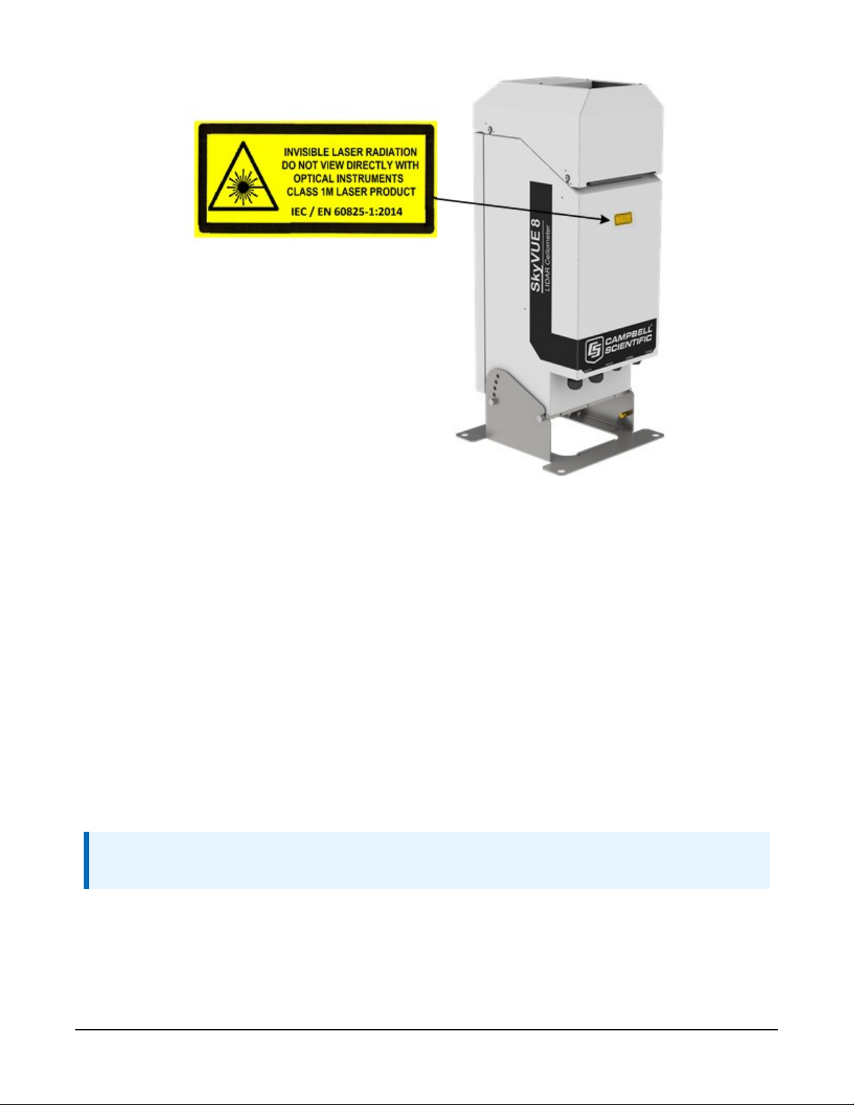
FIGURE 1-1. Location of laser warning label
Before removing the laser module, the sensor must be disconnected from both the mains supply
and the battery to ensure that the laser is turned off.
1.5 Electrical safety
Because the sensor is powered from potentially hazardous mains voltages, the power-supply
should be wired only by personnel qualified to install electrical equipment. For permanent
outside installations, this usually requires a certified electrician who is also familiar with local
electrical and safety legislation. Some general guidance is given in Connectors and wiring (p. 18),
but the responsibility for the installation lies with the installer.
The unit is tested for electrical safety before dispatch but may need subsequent testing according
to local practice.
NOTE:
The unit should only be serviced by trained personnel.
SkyVUE™8 (CS136) LIDAR Ceilometer 4
Page 10

WARNING:
Removal of electronic module covers or connectors while the unit is powered will expose the
operator to potentially hazardous voltages and risk damage to the sensor.
The SkyVUE 8 has electrical and laser warning labels on the exterior and interior of the unit.
It is fitted with a hex-key access panel. It is recommended that the hood and access panel door
are not opened in conditions of rain, hail or snow.
Isolate the sensor before removing internal components, including the cover to the avalanche
photodiode (APD) module. Only trained personnel should disassemble the instrument.
Mains connectors are shrouded to prevent touching of the contacts. The mains supply should be
isolated when connecting and disconnecting the cables to the sensor.
Where an isolator switch is fitted, this shall be a two-pole isolator, located as near to the sensor
as possible.
The SkyVUE 8 must be properly grounded by a licensed and qualified electrician to protect
against voltage leakage shock risk (Grounding (p. 15)).
Campbell Scientific recommends that RCD protection units be used with all sensors. See Power
connections (p. 20) for further information.
Mains powered heaters are enclosed to prevent contact.
CAUTION:
When powered, the heaters may operate automatically and without warning. They may
remain hot when not powered. Follow the isolation precautions, to avoid shock and burn
hazards.
The sealed battery has cables and protected connectors to prevent shorts. Avoid shorting the
battery to protect it from damage and to avoid burns to personnel through contact with hot
surfaces.
2. Product overview
2.1 Introduction 6
2.2 Optical measurement 8
2.3 Internal monitoring 8
2.4 Specifications 9
SkyVUE™8 (CS136) LIDAR Ceilometer 5
Page 11

2.1 Introduction
The SkyVUE 8 is a light detection and ranging (LIDAR) ceilometer that emits short pulses of near
infrared light into the atmosphere from a semiconductor laser. The pulses of infrared light are
scattered back by aerosols including cloud droplets. The time between transmission of the pulse
and the return signal gives the range, and therefore height, of the scattering aerosols. The
variation in the strength of the back-scattered light signal with height gives a profile of scatter
coefficients and allows identification of cloud bases. If significant scattering is detected without a
defined cloud base, then a vertical visibility can be calculated.
The control system of the SkyVUE 8 is divided into three modules, DSP, TOP and PSU as follows:
DSP (Digital Signal Processor) is the main data processing and communications unit of the
SkyVUE 8. It hosts two separate time keeping circuits that are cross checked. An alarm is triggered
if the circuits disagree.
TOP (top of the unit) provides safety shutdown features such as over and under laser output
level. It also contains the calibration circuitry and dirty windows system.
PSU (Power Supply Unit) controls the power supply including battery charging and deep
discharge protection.
The SkyVUE 8 has a rugged environmental enclosure that protects the instrument from the
harshest conditions and will measure the atmosphere with high stability and repeatability.
2.1.1 Cloud height detection
A scatter profile is measured as described in Measurement of the attenuated backscatter profile
(p. 93).
Cloud height detection is carried out as described in Cloud height calculation (p. 95). Up to four
cloud heights can be detected.
If clouds are not detected, the SkyVUE 8 will give one of these reports:
l No significant backscatter.
l Full obscuration determined but no cloud base detected. This is reported if the criteria for
detecting cloud base is not met but the integrated scattering coefficient reaches the limit
of vertical visibility below a set height limit. The default value is 2000m (6560ft) but can be
changed by the user. The height at which this occurs is given as vertical visibility.
l Some obscuration detected but determined to be transparent is reported if scattering is
detected but no cloud is detected and the calculated vertical visibility exceeds a set height
limit.
SkyVUE™8 (CS136) LIDAR Ceilometer 6
Page 12

If no cloud is detected but significant scattering is detected below 50m (160ft), then vertical
visibility is set to 0.
2.1.2 Sky condition
Sky condition is an assessment of cloud cover measured in units of eighths known as oktas. The
number of oktas is the density of cloud in eighths of that layer. The SkyVUE 8 can report up to
five layers of cloud when reporting sky condition. The algorithm used in the SkyVUE 8 follows
guidance in the ICAO 9837, Manual on Automatic Meteorological Observing Systems at
Aerodromes.
Sky condition is not an instantaneous measurement. It is based on cloud data for the previous 30
minutes, with cloud detection in the previous 10 minutes given an extra weighting. Therefore, sky
condition is not available until sufficient data has been collected. See Sky condition algorithm
description (p. 96) for more detail.
2.1.3 Backscatter profile reporting
Several possible data messages give the two-way attenuated backscatter profile. This consists of
2048 groups of five-character values (10,240 characters in total). Each character is 8 bits long and
therefore each 5 figure group is 40 bits. They are given as signed two complement integers and
numbers greater than 239–1 represent negative integers.
NOTE:
After 1600, the remaining groups are all of 00000.
Therefore, each group actually represents negative, a value between –239to +(239–1), rather than
0 to (240–1), which would be the case for unsigned, positive, 40-bit integers.
Apply the following two-stage process to correct the decimal value:
1. Convert the hexidecimal characters to a decimal number.
2. If the number resulting from this conversion is greater than 1048575, subtract
1,099,511,627,776, which is 240.
To use this backscatter coefficient in units of sr-1m-1, the sensor multiplies the calculated decimal
number by a factor of 10-8. The values are scaled by the Attenuated_SCALE parameter, see
Table 5-1 (p. 28).
NOTE:
The profile is not corrected for tilt angle even if cloud heights are corrected.
SkyVUE™8 (CS136) LIDAR Ceilometer 7
Page 13
2.2 Optical measurement
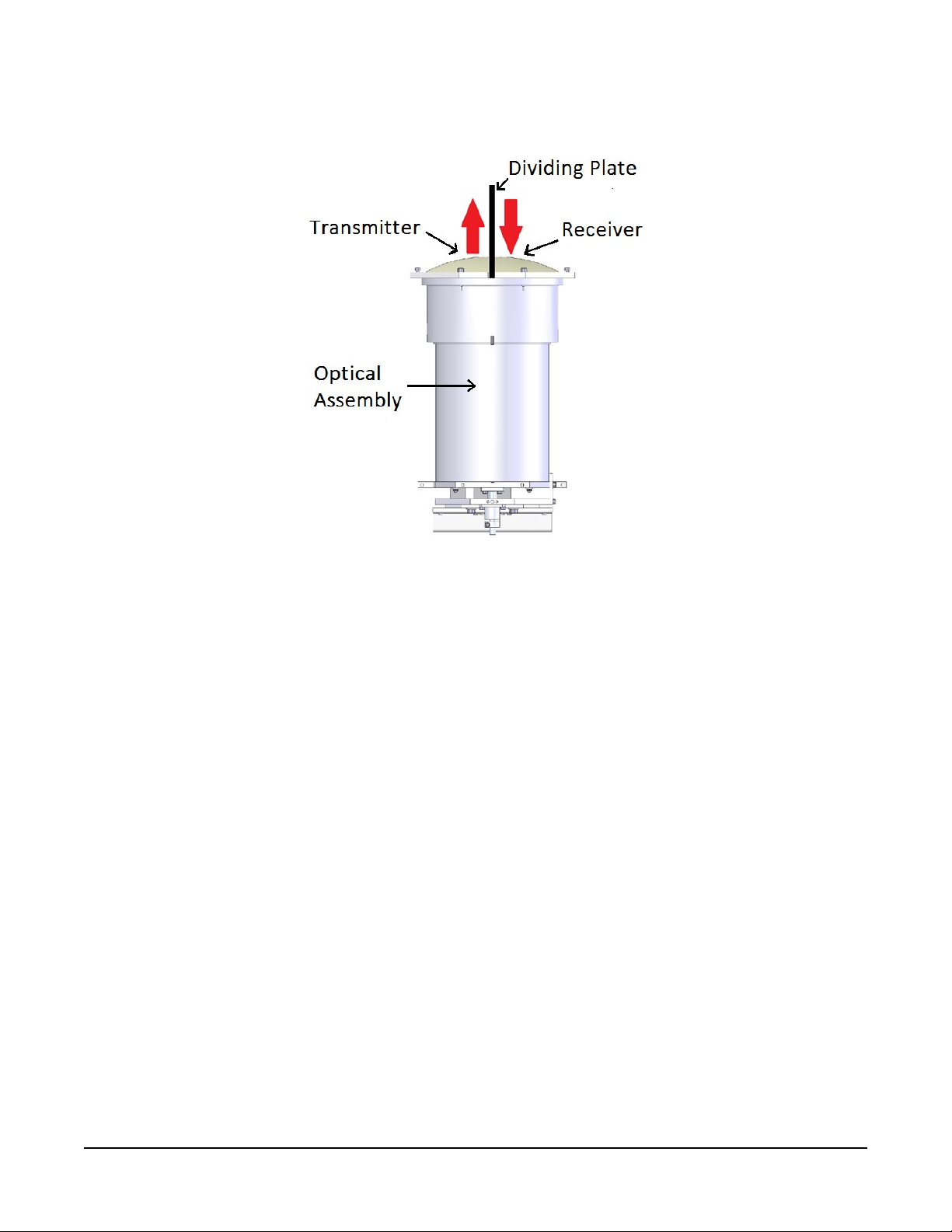
FIGURE 2-1. Principle of operation
2.2.1 Optical arrangement
The SkyVUE 8 uses a single biaxial lens design that increases optical signal-to-noise ratio, while
maintaining Class 1M eye safety by integrating larger optics into a compact package (see FIGURE
2-1 (p. 8)). Half of the lens is used by the transmitter, and the other half is used by the receiver.
This design provides an alternative to traditional two lens or common-optics designs. The optical
isolation of traditional biaxial systems is maintained to increase detector sensitivity, while the low
overlap onset height of common-optics systems is incorporated to allow measurements at close
ranges.
2.3 Internal monitoring
The SkyVUE 8 monitors window contamination, key voltages and currents, internal temperature
and relative humidity, and other parameters relevant to its performance. Data messages (see
Operation (p. 25)) include this information allowing remote diagnosis of the SkyVUE 8 condition.
In addition, a special status message can be polled.
SkyVUE™8 (CS136) LIDAR Ceilometer 8
Page 14

2.4 Specifications
2.4.1 Measurement specifications 9
2.4.2 Mechanical specifications 9
2.4.3 Electrical specifications 10
2.4.4 Optical specifications 12
2.4.5 Environmental specifications 12
2.4.6 Communications specifications 12
2.4.7 Compliance and testing 13
2.4.1 Measurement specifications
Maximum reporting range: 8 km (26,250 ft)
Minimum reporting resolution:
Hard target range accuracy:
Reporting cycle:
Cloud layers reported:
5 m (15 ft)
± 0.25% ± 4.6 m (15 ft)
2 to 600 s
Up to four layers reported
reported in Sky Condition.
2.4.2 Mechanical specifications
Height: 737 mm (29 in)
Width: 294 mm (11.6 in)
Depth: 240 mm (9.5 in)
Total weight: 18 kg (40 lb)
Shipping weight: 24.6 kg (54 lb)
Base plate:
316 x 316 mm (12.4 in x 12.4 in)
, excluding cables
, instantaneously. Up to five layers
SkyVUE™8 (CS136) LIDAR Ceilometer 9
Page 15
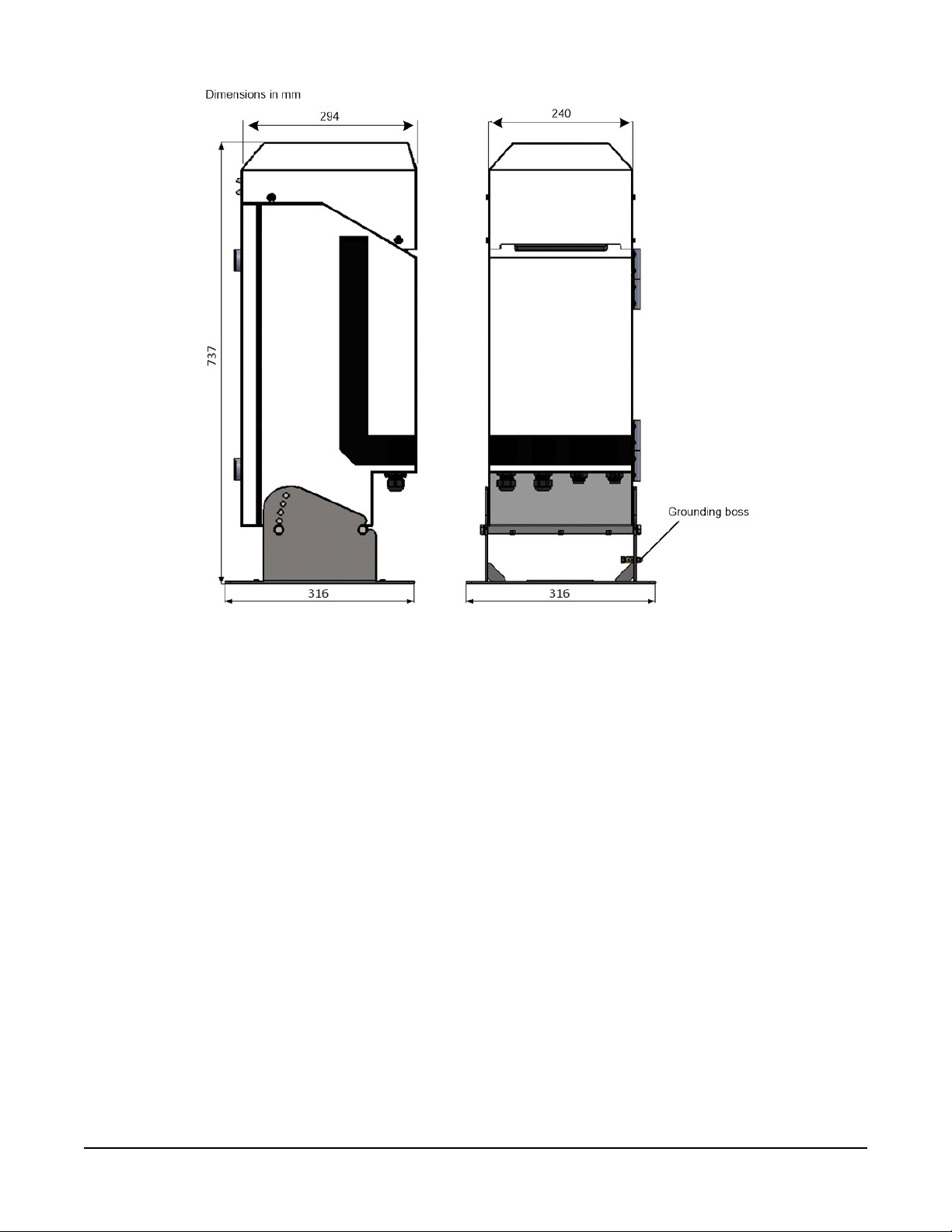
FIGURE 2-2. SkyVUE 8 dimensions
2.4.3 Electrical specifications
Power required: Nominal 115 VAC (106 to 137 VAC) or nominal 230 VAC (216
to 253 VAC) (automatic selection), 47 to 63 Hz, 380
maximum
W total
DSP:
12V OUT: 12 VDC /
Heater: Input not used with AC heaters.
Hood heater: 220
Internal heater: 110
Fuses:
DSP fuse:
10 to 40 VDC input;1A at 12 VDC;
1.7 A for optional or external equipment (if the
SkyVUE 8
14VDC for this to be available
W, maximum
HBC 5A (T)
is using a DC supply,
W, maximum
(not available in DC operation)
(not available in DC operation)
SkyVUE™8 (CS136) LIDAR Ceilometer 10
0.5
A at 24 VDC
this must be greater than
.)
Page 16
PSU fuse:
HBC5A(T)
All fuses are 5 x 20 mm slow blow (T) and are the same for
both 115VAC and 230VAC.
Battery:
The heaters are resistive, which is advantageous when connected to generators or when current
consumption is important.
Internal 12V, 7Ah sealed lead-acid battery. The power supply
is equipped with a system to prevent deep discharge of the
battery.
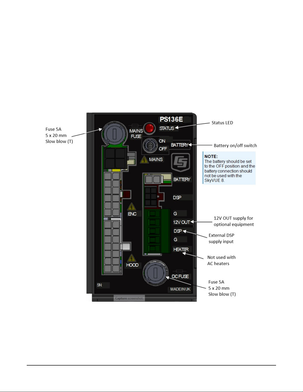
FIGURE 2-3. PSU types
SkyVUE™8 (CS136) LIDAR Ceilometer 11
Page 17

2.4.4 Optical specifications
Pulse duration:
Pulse frequency:
Wavelength:
Half-angle laser divergence: 0.44
Field of view: 2.0
Laser lifetime:
Eye safety class:
100 ns
10 kHz
912 ± 5 nm
mrad
mrad
10 years typical
1M
2.4.5 Environmental specifications
Standard operating
temperature range:
Battery temperature range:
Relative humidity range:
IP rating:
–40 to 60 °C
–20 to 50 °C (alternative battery types available)
0 to 100%
IP 66
(excluding battery)
Maximum wind speed:
55 m/s
2.4.6 Communications specifications
Supported serial settings:
Supported data rates: 300 baud 19200 baud
Supported standards:
8 bits, no parity, 1 stop bit (default)
7 bits, even parity, 1 stop bit
7 bits, odd parity, 1 stop bit
600 baud 38400 baud
1200 baud 57600 baud
2400 baud 76800 baud
4800 baud 115200 baud (default)
9600 baud
RS-232 (default)
RS-485 full duplex
RS-485 half duplex
SkyVUE™8 (CS136) LIDAR Ceilometer 12
Page 18

Signal voltage levels:
Minimum value Nominal value Maximum value
RS-232 communications
RS-232 input threshold low 0.8 V 1.5 V –
RS-232 input threshold high – 2.0 V 2.4 V
RS-232 input absolute maximum –15 V – +15 V
RS-232 input resistance 12 KΩ – –
RS-232 output voltage low – – 0.4 V
RS-232 output voltage high (into 3 KΩ) 4.4 V – –
RS-485/422 communications
RS-485/422 input threshold voltage –0.2 V – +0.2 V
RS-485/422 output (unloaded) – – 5V
RS-485/422 output (load 50 Ω) 2 V – –
Maximum voltage at any terminal –7 V – +7 V
USB Service Port USB1.1 and 2.0 compatible, fixed 115200 baud.
2.4.7 Compliance and testing
NOTE:
Further details regarding compliance and testing are available upon request.
EMC compliance:
Electrical safety compliance:
Laser safety compliance:
Eye safety standard:
Vibration:
Frequency range:
EN 61326-1:2013
EN 61010-1:2010
EN 60825-1:2014
Class 1M
BS EN 60068-2-6:2008 Test Fc: Vibration (Sinusoidal)
5 to 150 Hz (exceeds Lloyd's Register test levels)
SkyVUE™8 (CS136) LIDAR Ceilometer 13
Page 19

3. Initial preparation and checks
The following steps will provide basic familiarization with the SkyVUE 8 and perform basic
functionality checks. To do these, open the door and connect the battery (see Connecting the
back-up battery (p. 22)).
WARNING:
The laser begins operating as soon as the battery is connected. Do not point the laser in any
direction where it could be viewed with magnifying optics.
The green LED visible from above should flash once every 10 seconds (see FIGURE 5-2 (p. 61)).
Connect the SkyVUE 8 USB port (see FIGURE 4-5 (p. 22)) to a computer and use a terminal
emulation program to set to 115200 baud, 8N1 bits/parity settings.
The computer should identify the USB connection and allocate a port number. Enter the port
setting in the terminal emulator program. Older computer operating systems may need
upgrading or additional software.
The SkyVUE 8 will output message type 004 (default) every 30 seconds (see CS messages (p. 63)).
Use the open 0 command to open the terminal mode. You should now see the prompt CS136>.
Type Status to see the sensor status information described in Status command (p. 46). If using
date/time information, checked it since the date/time can drift up to ±14 seconds per day.
If the unit has been in storage or transit for more than a few months, the clock battery may be
discharged. However, it will charge from the back-up battery or mains power.
Use the Close command to exit the terminal mode. It will close automatically after 10 minutes of
inactivity.
If you are not installing the unit and connecting mains power, you should disconnect the battery
to avoid it being discharged.
SkyVUE™8 (CS136) LIDAR Ceilometer 14
Page 20

4. Installation
4.1 Location and orientation 15
4.2 Grounding 15
4.3 Mounting the SkyVUE 8 16
4.4 Tilt angle 17
4.5 Connectors and wiring 18
4.6 Connecting the back-up battery 22
4.7 Bird spike kit 23
4.8 Storage information 24
4.1 Location and orientation
The SkyVUE 8 measures environmental variables and is designed to be located in harsh weather
conditions. However, there are a few considerations to take into account if accurate and
representative data from a site are to be obtained.
To reduce the service frequency with the unit, place the SkyVUE 8 away from sources of
contamination. More regular maintenance will be required when the instrument is placed in
areas where contamination is unavoidable or where measurements may be safety related.
Take care that the orientation allows tilting in whatever direction is desired.
WARNING:
If installing at an airport, check and follow local guidance for allowed locations for a nonfrangible object 1 m (3.2 ft) tall. Please contact Campbell Scientific if frangible fittings are
required.
4.2 Grounding
The SkyVUE 8 must be properly grounded by taking a ground wire with a minimum cross
sectional area of 16mm2(0.62in) and maximum length of 10m (32.8ft) from the brass
grounding boss to an adequate grounding point. FIGURE 2-2 (p. 10)) shows the location of the
grounding boss.
SkyVUE™8 (CS136) LIDAR Ceilometer 15
Page 21
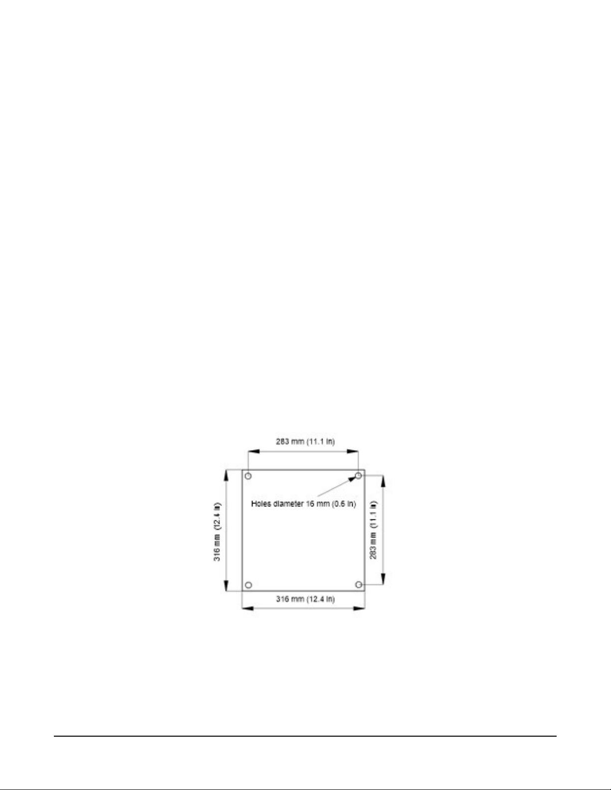
4.3 Mounting the SkyVUE 8
Mount the SkyVUE 8 by bolting to a firm, level foundation. When bolting down, ensure the
SkyVUE 8 can tilt in all desired directions. FIGURE 4-1 (p. 16) shows the mounting footprint. If a
suitable surface does not already exist, construct a concrete foundation, at least 600mm (23.6in)
square and 600mm (23.6in) deep, by using the following procedure:
1. Drill four 12mm (0.47in) diameter holes using the mount base as a template (see FIGURE
4-1 (p. 16)) to a depth of 77mm (3.03in).
2. Clean the holes of all debris.
3. Place washers and nuts on the ends of the wedge anchors supplied (to protect the threads
during installation).
4. Hammer the wedge anchors into the holes until the start of the threads are below the
surface.
5. Tighten the nuts until about 25mm (0.98in) of thread protrudes above the surface.
6. Remove the washers and nuts from the protruding length screw, then lower the SkyVUE 8
into place.
7. Secure the SkyVUE 8 with the washers and nuts.
8. If the surface is not level and flat, add washers under the base on one or more of the
foundation screws.
FIGURE 4-1. Mounting base footprint
SkyVUE™8 (CS136) LIDAR Ceilometer 16
Page 22

4.4 Tilt angle
The SkyVUE 8 can be tilted 6°, 12°, 18° or 24° from vertical. In tropical regions, tilting the sensor
north in the northern hemisphere and south in the southern hemisphere can prevent the sun
from shining directly into the sensor. The tilt angle also can reduce problems caused by direct
specular reflections from ice crystals, and prevent rain or snow from falling onto the window. To
adjust the tilt angle, remove the bolts shown in FIGURE 4-2 (p. 17), move the SkyVUE 8 to the
required tilt angle, and replace the bolts.
The SkyVUE 8 has tilt sensors in both axes to compensate the cloud height when the base is not
level. Set or disable cloud height compensation by using the UNITS command (Terminal mode
command examples (p. 27)). This feature is useful for mobile or marine applications. Profile data
is NOT compensated but tilt angles are included in data messages.
NOTE:
Increasing the tilt angle beyond 24° can cause significant errors in vertical visibility
measurements if scatter coefficients vary significantly with height.
FIGURE 4-2. Setting the tilt angle
SkyVUE™8 (CS136) LIDAR Ceilometer 17
Page 23
4.5 Connectors and wiring
4.5.1 Base connectors 18
4.5.2 Wiring using supplied Campbell Scientific cables 19
4.5.3 USB connection 21
4.5.4 I/O connection 22
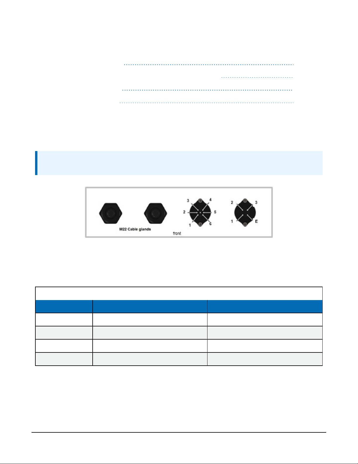
4.5.1 Base connectors
The SkyVUE 8 has two connectors on its base. One connector (6 pins) is for communications;
another connector (4 pins) provides power to the unit.
NOTE:
Tilting the unit provides better access to these connectors.
FIGURE 4-3. Connector layout
The function of the connector pins is shown in Table 4-1 (p. 18), Table 4-2 (p. 19), and Table 4-3
(p. 19).
Table 4-1: Function of the connector pins for the mains connector
Pin Function Color of supplied cable cores
1 Live Brown
2 Not connected NA
3 Neutral Blue
4 Earth Green/yellow
SkyVUE™8 (CS136) LIDAR Ceilometer 18
Page 24
Table 4-2: Function of the connector pins for the blower/heater connector
Pin Function Color of supplied cable cores
1 Neutral Black (1)
2 Fan + 12 VDC Black (2)
3 Thermistor Black (3)
4 Thermistor (0 V) Black (4)
5
6
E Earth Green/yellow
Table 4-3: Function of the connector pins for the communications connector
Pin on
connector on
SkyVUE 8
1 Red 8
2 Yellow 7
3 Green 5 Gnd
Color of
supplied cable
cores
Switched 230/115 VAC
high voltage heater
Switched 230/115 VAC
low voltage heater
9-pin D
connector
Black (5)
Black (6)
RS-485 half
RS-232
duplex
CTS (DCE)
B/D+
output
RTS (DCE)
input
RS-485 full
duplex/
RS-422
Y/TXD
non-inverting
B/RXD
non-inverting
4 Black Gnd Gnd
5 White 2
6 Blue 3
E Screen
RXD (DCE)
A/D–
output
TXD (DCE)
input
Z/TXD
inverting
A/RXD
inverting
4.5.2 Wiring using supplied Campbell Scientific cables
Two cables are supplied, each 10m (32.8ft) long. One is for the mains power supply and the
other is for communications.
SkyVUE™8 (CS136) LIDAR Ceilometer 19
Page 25

WARNING:
Incorrectly wiring the power cable can cause irrevocable damage to the unit and can cause
serious injury or death.
WARNING:
The power cable must not be carrying mains voltage when it is being connected or
disconnected.
4.5.2.1 Power connections
The following is a guide for wiring and installing a permanent power supply.
As the sensor is used outside, a qualified electrician should install the power cables. Please check
local safety regulations.
Ensure that the termination type, cable type, and cable run of the mains power source complies
with local regulations and fits the installationrequirements.
The power source needs to provide the correct voltage, frequency, and current in excess of the
power requirement of the system.
Voltage requirements: 106 to 137 VAC or 216 to 253 VAC (auto select)
Power requirements: 380 W
Input frequency: 47 to 63 Hz
The power source needs fuses with ratings of 5A or larger and a slow-blow design. Cable
extensions or replacement cables should be capable of carrying current in excess of that fuse
rating.
Include a two-pole isolator as close to the sensor as is possible.
The power cable needs three conductors (live, neutral, and a protective earth), normally with IEC
wiring colors to match those used.
The equipment requires the connection of earth ground using the earth wire of the power
connector/cable or via the earth stud on the sensor base. Ensure the earth connection at the
power source is suitable for this purpose.
This equipment also requires correct connection of the live and neutral conductors — make sure
these are identified and wired correctly at the power source.
Normally, fit the power source with its own or system wide earth leakage breaker (also known as
an RCD).
For short term testing of the sensor, fit the power cable with a suitable plug can be fitted to the
end of the power cable and the sensor plugged into a standard mains supply capable of
SkyVUE™8 (CS136) LIDAR Ceilometer 20
Page 26

providing 5A at the rated voltage. If this is done, the earth wire of the sensor must be connected
to a suitable protective earth point.
For DC operation, the SkyVUE 8 requires a 10 to 40VDC supply capable of 1A at 12VDC or 0.5A
at 24VDC.
4.5.2.2 Communications connections
The communications cable terminates at one end with a removable 9-pin, D-connector (DB9).
The D-connector connects directly to a computer or data logger such as the Campbell Scientific
CR1000X using a suitable interconnecting cable such as the SC110. FIGURE 4-4 (p. 21). The
connector can easily be removed for direct connection to screw terminals.
See www.campbellsci.com/downloads/skyvue-example-programs for CRBasic programs that
connect the SkyVUE 8 to a Campbell Scientific data logger.
CAUTION:
The supplied cable is not recommended for lengths greater than 10m (32.8ft). Longer
RS-485 cables should incorporate twisted pairs. Contact Campbell Scientific if needing longer
cable lengths.
FIGURE 4-4. Cable connections
4.5.3 USB connection
The USB port provided inside the enclosure is for on-site maintenance. It supports
communication of commands to the SkyVUE 8 and responses in the same form as the main serial
port, except the baud rate is fixed at 115200 (see FIGURE 4-5 (p. 22)).
SkyVUE™8 (CS136) LIDAR Ceilometer 21
Page 27
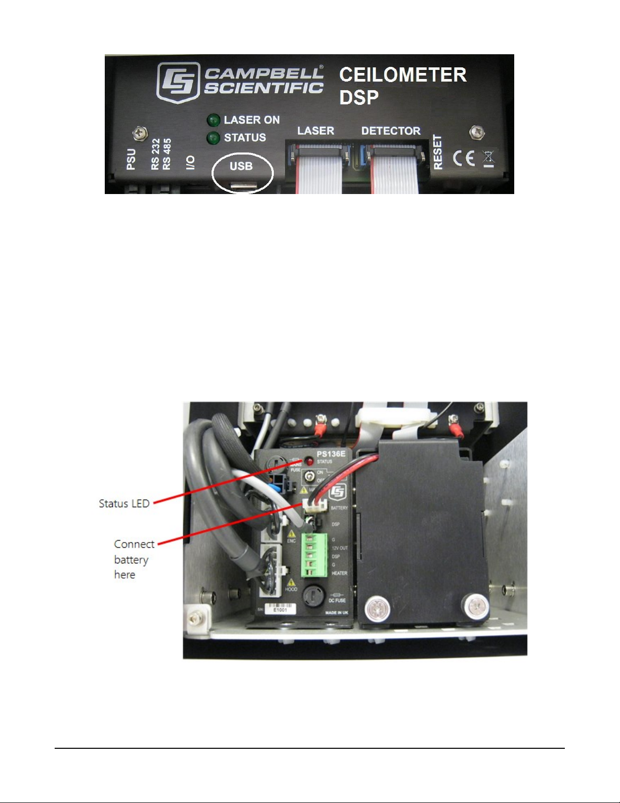
FIGURE 4-5. USB port
4.5.4 I/O connection
The I/O port is only used for factory setting of the instrument.
4.6 Connecting the back-up battery
The SkyVUE 8 is shipped with the back-up battery disconnected and includes desiccant used for
transport. Before using the unit, open the door, connect the internal battery (FIGURE 4-6 (p. 22),
remove the desiccant, and close the door.
FIGURE 4-6. Connecting battery
SkyVUE™8 (CS136) LIDAR Ceilometer 22
Page 28
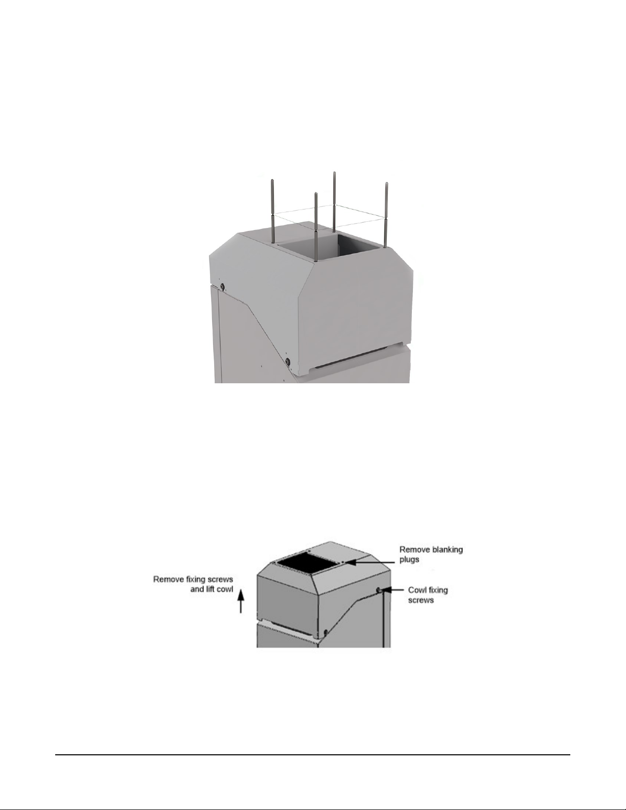
4.7 Bird spike kit
The optional bird spike kit deters birds from sitting on the SkyVUE 8. It includes four stainlesssteel spikes with rounded ends and a small reel of stainless-steel wire. The following figure shows
installed bird spikes.
FIGURE 4-7. Ceilometer bird spike kit installed
To install the bird spikes, remove the cowl and blanking plugs from the cowl (FIGURE 4-8 (p. 23).
If the SkyVUE 8 is an older unit without pre-existing holes, then drill four holes each 4.5mm
(0.17in) diameter, evenly spaced around the aperture and 10mm (0.39in) in from the edge. For
each hole, place a nut and washer then thread the spike into the hole. Tighten the nuts and
washers (see FIGURE 4-9 (p. 24)). Replace the cowl on the SkyVUE 8.
FIGURE 4-8. Preparing the SkyVUE 8 for installing the bird spikes
SkyVUE™8 (CS136) LIDAR Ceilometer 23
Page 29
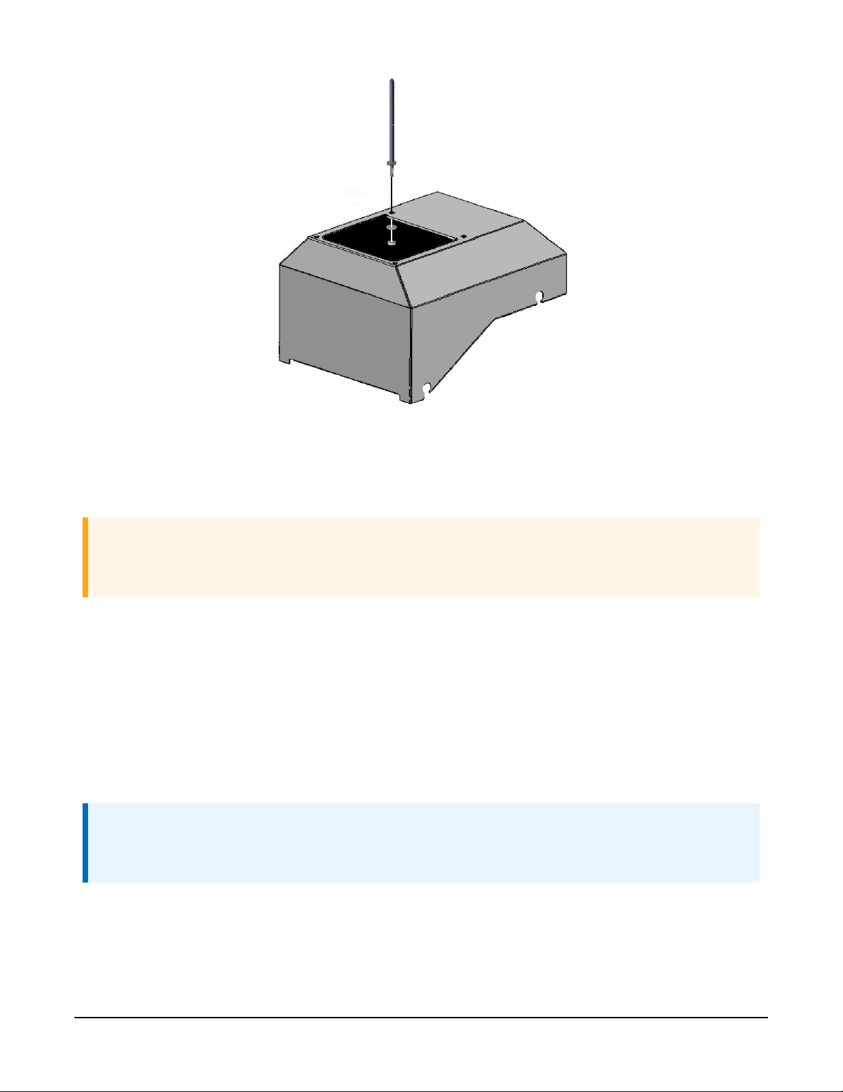
FIGURE 4-9. Attaching bird spikes to the SkyVUE 8 cowl
Wrap the stainless steel wire around each spike using the grooves in the spike then wrap it back
on itself.
CAUTION:
Do not tighten the wire too much as it may pull the spikes inwards and obscure the field of
view of the SkyVUE 8 optics.
Only use one strand of wire to reduce the possibility of water drops being collected.
Check the wire during maintenance and replace if necessary.
4.8 Storage information
Store the SkyVUE 8 in a dry place at –40 to 70 °C, preferably with the enclosures securely
fastened. Protect the optics from possible accidental damage. Disconnect the back-up battery
when storing the SkyVUE 8.
NOTE:
If the battery remains connected during storage, the unit will be powered until the battery
voltage falls below a shut-down threshold.
SkyVUE™8 (CS136) LIDAR Ceilometer 24
Page 30

NOTE:
Storing the SkyVUE 8 below 0.0 °C will increase the start-up time by up to ten minutes. At –20
°C, the SkyVUE 8 will not achieve full accuracy for an hour.
NOTE:
Remove the battery if the SkyVUE 8 is to be stored outside the –20 to 50 °C temperature
range.
5. Operation
5.1 Terminal mode 25
5.2 Restoring factory defaults 60
5.3 LED indicator 61
5.1 Terminal mode
5.1.1 Entering/exiting the SkyVUE 8 terminal mode 26
5.1.2 Terminal mode commands general 26
5.1.3 Terminal mode command examples 27
5.1.4 Application command message types 41
5.1.5 MCFG command message types 43
5.1.6 Measurement and message intervals 44
5.1.7 Status command 46
5.1.8 Message polling 54
5.1.9 Loading a new operating system (OS) 55
5.1.10 Stratocumulus backscatter calibration 56
5.1.11 CRC-16 codes on terminal commands 58
5.1.12 Service command 58
5.1.13 Locked features 60
SkyVUE™8 (CS136) LIDAR Ceilometer 25
Page 31

5.1.1 Entering/exiting the SkyVUE 8 terminal mode
Use the OPEN Sensor_ID Password command to enter the menu system. The menu will
time out and close automatically if not used for ten minutes.
Sensor_ID is the SkyVUE 8 identification, a single character 0-9, a-f, A-F case sensitive. Default
is 0. Enter the password if using one. The following text should be displayed:
CS136>. The SkyVUE 8 is now ready for terminal mode commands.
The SkyVUE 8 commands are not case sensitive, but the parameters and password are case
sensitive.
Example of the open command followed by the 0 parameter:
OPEN 0
Example of the open command with the password Secret:
OPEN 0 Secret
5.1.2 Terminal mode commands general
Table 5-1 (p. 28) provides a summary of the terminal mode commands.
To send commands that setup and control the SkyVUE 8, use the terminal interface, data logger,
or terminal emulators built into many Campbell Scientific software products.
NOTE:
To load an operating system (OS), you need a terminal emulator with XMODEM protocol
such as Tera Term.
Use the following settings:
Setting RS-232/422/485 interface (default) USB service port
RS-232
Baud rate 115200 115200
Data bits 8 8
Parity none none
Stop bits 1 1
Flow control none none
The baud rate of the SkyVUE 8 must match the port setting baud rate in the terminal emulator.
The SkyVUE 8 should now be ready to accept commands.
SkyVUE™8 (CS136) LIDAR Ceilometer 26
Page 32

NOTE:
Commands will always output all parameters on a new line after a CR LF (carriage return and
line feed) and then the SkyVUE 8 prompt CS136>. If you only want to see parameter values
without changing them, then enter the command without parameters. If a particular
parameter did not need changing, then the parameter can be replaced with a comma (,).
Back space will abort the command.
5.1.3 Terminal mode command examples
How to enter a command
Example 1
The following text shows an example of setting up the SkyVUE 8 serial port. This example sets the
serial port to RS-232 hand shaking at 115200 bps, 8 data bits, no parity and if it was in RS-485
mode, then a 100ms turn around delay.
serial 0 10 0 100
You could also type the following to obtain the same results as the RS-485 turn around delay is
not needed:
serial 0 10 0
To change only the data baud rate, you can replace mode parameter, with a comma (,) as shown
below.
serial , 10
Alternatively if you just wished to change the parity to 8-bits no parity, then type the following:
serial , , 0
You do not need to replace the remaining parameters with a comma (,); you only need to replace
the ones up to the parameter you wish to edit.
NOTE:
Leave a space character between the command and the parameters as shown in the
examples.
Example 2
Entering the MCFG command, as shown below, will set the sensor to send messages at 10 second
intervals and to send one message only with the message number 112.
MCFG 10 112 0 0 0 0 (return)
The four zeros indicate that no other message outputs have been set. The MCFG command is
described in Table 5-1 (p. 28).
SkyVUE™8 (CS136) LIDAR Ceilometer 27
Page 33

Table 5-1: Summary of the terminal mode commands available
Command
ALARMS Angle
APPLICATION
parameter block
Application_n Application_n selects pre-configured user
Parameter/
Description
Angle is the threshold tilt angle of the sensor beyond
which an alarm will be flagged. The settable range is
0 to 90.0 degrees tilt and the default is 45.0 degrees.
settings optimized for a specific application. For the
following values of n:
0 = Help
10 = Aviation
20 = Research
40 = Meteorology
225 = User defaults
The default application for the SkyVUE 8 is 10,
Aviation. Settings adjusted by the APPLICATION
command include settings in BS, MCFG, and UNITS.
BS
(see
Measurement
and message
intervals (p. 44)
for more
information on
compatibility of
different
parameters)
Attenuated_
SCALE,
BS_Av_Time,
Noise_Gate,
Measurement_
Period,
Rolling_
Average,
Message_
Interval
BS_Temporal_
Filter_Mode
Rules for BS command are:
BS_Av_Time <= Measurement_Period-1s.
Message_Interval must be a multiple of
Measurement_Period.
Attenuated_SCALE is the scalar for the
attenuated backscatter percent. 0.001 to 100%
(default 100%)
BS_Av_Time is the backscatter average time in
seconds. 1 to 30 (default 7).
Note: Must not be greater than Measurement_
Period – 1.0
Noise_Gate controls the noise threshold applied
to back-scatter.
Noise_Gate = -1000, all backscatter range is
corrected.
SkyVUE™8 (CS136) LIDAR Ceilometer 28
Page 34

Table 5-1: Summary of the terminal mode commands available
Command
Parameter/
Description
parameter block
Noise_Gate = 0.0 to 1000.0, standard deviation
(default 2) for noise threshold. Only backscatter
above this is range corrected.
Measurement_Period = 0 or 2 to 600 seconds
(default 10). If set to 0 and the SkyVUE 8 is polled, it
will output the last measurement made. If between 2
and 600 seconds, the SkyVUE 8 continually outputs
messages. For sky condition output, Campbell
Scientific recommends setting the measurement_
Period ≤ 30 seconds. If a measurement_
Period is greater than 30 seconds, the sky condition
algorithm will be less able to resolve coverage for
higher layers.
Note: Must be a sub multiple of Message_
Interval
Rolling_Average = 1 to 29 (default 3). This is the
number of measurement_periods to use in a
rolling average of the backscatter.
Message_Interval is the message interval in
seconds. Range is 2 to 600 seconds (default 10 s); 0
gives polled messages.
Note: Must be a multiple of Measurement_
Period
BS_Temporal_ Filter_Mode allows the
selection of backscatter filtering modes.
0 = Averaging
1 = Median signal processing
Default setting is 1, the median mode for aviation.
CLOSE No parameters Closes the terminal interface to allow normal
message output and saves new settings to flash nonvolatile storage.
SkyVUE™8 (CS136) LIDAR Ceilometer 29
Page 35

Table 5-1: Summary of the terminal mode commands available
Command
CLOUDMODE CloudMode_A
DEFAULTS
GETUSER
Parameter/
parameter block
No parameters Loads factory defaults
Description
CloudMode_A turns on a filter that reports the
highest cloud during precipitation to avoid
precipitation from being reported as low cloud.
0 = Filter Off
1 = Filter On (default). Reports the highest cloud
during precipitation
Reads all user settings as a string of text. Parameters
are read in the following order:
user = text user
volVer = user volume version
OS_VER = DSP OS version
PsuOsVer = PSU OS version
TopOsVer = TOP OS version
Id = SkyVUE 8 ID
Pw = SkyVUE 8 password
terminalCrc = terminal crc mode
terminalTimeout = terminal timeout
unitsTiltMode = units and tilt mode
hoodHBMode = hood heater / fan heater mode
hoodHBTestInt = hood heater / blower test
interval in hours
battBoost_mV = boost voltage used for battery
charging mV
battCharge_mA = battery charge current mA
psuPresent = PSU present switch
hoodHBNormSpeed = fan voltage for normal
speed mV
SkyVUE™8 (CS136) LIDAR Ceilometer 30
Page 36

Table 5-1: Summary of the terminal mode commands available
Command
Parameter/
Description
parameter block
hoodHBHighSpeed = fan voltage for high speed
mV
hoodHBLowSpeed = fan voltage for low speed mV
intHMode = internal heater mode
message[0] = fields for message 0
message[1] = fields for message 1
message[2] = fields for message 2
message[3] = fields for message 3
message[4] = fields for message 4
messagePeriod = output message period in
seconds
heightOffset= height offset meters
bsAvTime= backscatter average time in seconds
laserMode = laser operation mode
laserPower = laser power
laserHeater = laser heater mode
attenuatedSCALE = attenuated backscatter
scaling factor
logInterval = debug logging interval
measurementPeriod = measurement interval in
seconds
serMode = serial port mode
baudSel = serial port baud rate mode
dataParityStop = serial port parity mode
rx2txTimeout = serial port RX to TX turnaround
time
snrMarginBoundary = onset of backscatter
detection threshold
SkyVUE™8 (CS136) LIDAR Ceilometer 31
Page 37

Table 5-1: Summary of the terminal mode commands available
Command
Parameter/
Description
parameter block
snrMarginDetector = cloud detection threshold
alphaGuessEnd = cloud alpha guess at boundary
alphaMin = cloud detection alpha minimum
Vcld_D = cloud detection
delta_Vcld_D = cloud detection
vis_Av_T = cloud detection
alphaGuess = visibility initial alpha guess
ratioLevel = visibility ratio
alphaMin = visibility alpha minimum
cap = visibility cap in meters
tiltLimit = tilt limit in degrees used by alarms
noiseGate = attenuated backscatter noise gate
mode
vvLimit_percent = sky condition report vertical
visibility %
alphaGuessStart= cloud detection alpha guess
at lowest height bin
reserved
reserved
reserved
reserved
reserved
reserved
cloudMode = cloud detector mode parameter
(03072019a)
CRC = 4-digit character. CRC calculated from the u
up to but not including the CRC using the standard
CRC-16.
SkyVUE™8 (CS136) LIDAR Ceilometer 32
Page 38

Table 5-1: Summary of the terminal mode commands available
Command
Parameter/
Description
parameter block
Note: Many parameters are not adjusted. This
command allows a reliable technique for copying
full settings from one SkyVUE 8 to another with the
SETUSER command.
A typical response to the GETUSER command is:
>>>>> COPY FROM START OF NEXT LINE >>>>>
user 7 007638-6da 106 510 0 , 0 10 2 0 1 14520 400 1
1000 1000 2000 0 1 0 0 0 0 10 0.000E+00 2.000E+00 1
1.000E+00 0 1.000E+00 0 10 1 0 10 0 100 4.000E+00
6.000E+00 2.000E-03 2.500E-04 1.000E+03 2.200E+01
4.800E+03 1.000E-01 9.000E-01 2.500E-04 2.000E+03
4.500E+01 2.000E+00 50 2.00E-03 3.000E+01
1.500E+02 1.800E+00 5.000E+00 1.000E+01 150 98b2
<<<<< TO START OF THIS LINE <<<<<
HEATERS Hood
Internal
Laser
Test_interval
HELP
No parameters Calls up a list of user commands with brief
Sets or reads heater settings as follows:
Hood = 0, Hood blower and heater OFF
Hood = 1, Hood blower ON and heater OFF
Hood = 2, Hood blower ON and heater ON
Hood = 3, Hood blower and heater AUTO (default)
– (see note (1) below).
Internal = 0, Internal heater OFF
Internal = 1, Internal heater ON
Internal = 2, Internal heater AUTO (default)
Laser = 0, laser heater off
Laser = 1, laser heater on (default)
Test_interval = 1 to 168 hours (default 24
hours). Heater/Blower test interval
descriptions
SkyVUE™8 (CS136) LIDAR Ceilometer 33
Page 39

Table 5-1: Summary of the terminal mode commands available
Command
HOFFSET Height_offset
ID Sensor_ID
LASER Laser
LASEROFF
Parameter/
parameter block
Laser_Power
No parameters Instructs the SkyVUE 8 to turn the laser off until either
Description
Height_offset is the offset to be added or
subtracted in the range of ±1000 m (±3281 ft).
Positive values are added to measured height and
negative values are subtracted from measured height.
The default is 0.
Reads or sets the sensor ID, a single character, 0-9, a z or A - Z, case sensitive. Default ID = 0.
Note: Lower case letters are not allowed if using a
CT25K message.
Laser = 0, laser off after power up (user must
switch laser on)
Laser = 1, laser on after power up (default)
Laser_Power = 20% to 100%, default 100%
a power cycle or the sensor is instructed to turn the
laser back on.
LASERON
LOADOS Module
MCFG Message_
No parameters Instructs the SkyVUE 8 to try and turn the laser on
Interval
Message_ID_A
Message_ID_B
Message_ID_C
Message_ID_D
Message_ID_E
Loads new operating system.
This command must be sent using XMODEM
protocol. Refer to Loading a new operating system
(OS) (p. 55) for more information.
Set or read message configuration
Message_Interval is the message interval in
seconds. Range is 2 to 600 s (default 10); 0 gives
polled messages.
Note: This command may affect measurement
parameters within the BS command. See
Measurement and message intervals (p. 44).
Message_ID is the message type to output
between 0 and 999 (default 001). If Message_ID =
SkyVUE™8 (CS136) LIDAR Ceilometer 34
Page 40

Table 5-1: Summary of the terminal mode commands available
Command
Parameter/
parameter block
OPEN ID
Password
PASSWORD Password
Description
0, no message type is output. Up to five messages can
be set (refer to MCFG command message types (p.
43)).
Opens the SkyVUE 8 terminal mode
ID = Sensor ID as per the terminal ID command.
AnySkyVUE 8 with firmware OS2 or newer will
respond to global ID = 99, regardless of its own ID
number.
Password = The sensors user password as per the
terminal PASSWORD command. The default is no
password.
Sets or clears a password from 1 to 10 characters in
length. Valid characters, 0-9, a - z or A – Z, and letters
are case sensitive. Typing the PASSWORD command
without any parameters clears the password. The
default is no password.
POLL Sensor_ID
Message_ID
POWEROFF
REBOOT
No parameters Prepares the PSU to power down the SkyVUE 8 even
No parameters Forces a system reboot. This will restore previously
Requests Message_ID from Sensor_ID.
Refer to Message polling (p. 54) for more information
on this command
Note: If Message_ID is omitted, the SkyVUE 8
outputs the message configured by MCFG.
if the battery is connected. As soon as the mains
supply is disconnected, the SkyVUE 8 will power off
and NOT run on battery back-up. The SkyVUE 8 can
be re-activated with battery back-up enabled by
reconnecting the mains supply. You will be asked to
confirm.
saved user settings. Any unsaved changes will be lost.
(Settings are saved in the terminal mode when the
SkyVUE™8 (CS136) LIDAR Ceilometer 35
Page 41

Table 5-1: Summary of the terminal mode commands available
Command
SCCAL
SERIAL Mode
parameter block
No parameters but
user interaction
required
Baud
Bits_Parity
Delay
Parameter/
Description
CLOSE command is typed, which exits the terminal
mode).
Stratocumulus backscatter calibration.
This requires a human observer to confirm a stable
Stratocumulus cloud layer between 250 m to 2500 m
without holes, precipitation or reduced visibility and
has been stable for at least 10 minutes prior to
running this command. See Stratocumulus
backscatter calibration (p. 56) for more information.
Set or read the serial port.
Mode = 0, RS-232, full duplex (default)
Mode = 1, RS-232, half duplex
Mode = 2, RS-485, full duplex
Mode = 3, RS-485, half duplex
Mode = 4, reserved
Mode = 5, RS-422, full duplex
Baud = 0, 300 baud
Baud = 1, 600 baud
Baud = 2, 1200 baud
Baud = 3, 2400 baud
Baud = 4, 4800 baud
Baud = 5, 9600 baud
Baud = 6, 19200 baud
Baud = 7, 38400 baud
Baud = 8, 57600 baud
Baud = 9, 76800 baud
Baud = 10, 115200 baud (default)
Bits_Parity = 0, 8 bits, no parity, 1 stop bit
SkyVUE™8 (CS136) LIDAR Ceilometer 36
Page 42

Table 5-1: Summary of the terminal mode commands available
Command
SERVICE
SETUSER
Parameter/
parameter block
(default)
Bits_Parity = 1, 7 bits, even parity, 1 stop bit
Bits_Parity = 2, 7 bits, odd parity, 1 stop bit
Delay = delay time, in milliseconds, before
transmitting (RS-485 half-duplex mode only). Range:
0 to 100 ms (default 100 ms).
No parameters but
user intervention
required
String Load all user settings as a string of text.
Performs a service procedure
(not changed) = parameter will not be updated and
the previously set value will persist.
String = user (not changed)
Description
volVer = user volume version (not changed)
OS_VER = DSP OS version (not changed)
PsuOsVer = PSU OS version (not changed)
TopOsVer = TOP OS version (not changed)
Id = SkyVUE 8 ID (not changed)
Pw = SkyVUE 8 password (not changed)
terminalCrc = terminal crc mode
terminalTimeout = terminal timeout
unitsTiltMode = units and tilt mode
hoodHBMode = hood heater / fan heater mode
hoodHBTestInt = hood heater / blower test
interval in hours
battBoost_mV = boost voltage used for battery
charging mV
battCharge_mA = battery charge current mA
SkyVUE™8 (CS136) LIDAR Ceilometer 37
Page 43

Table 5-1: Summary of the terminal mode commands available
Command
Parameter/
Description
parameter block
psuPresent = PSU present switch
hoodHBNormSpeed = Fan voltage for normal
speed, mV
hoodHBHighSpeed = Fan voltage for high speed,
mV
hoodHBLowSpeed = Fan voltage for low speed,
mV
intHMode = internal heater mode
message[0] = fields for message 0
message[1] = fields for message 1
message[2] = fields for message 2
message[3] = fields for message 3
message[4] = fields for message 4
messagePeriod = output message period in
seconds
heightOffset = height offset meters
bsAvTime = backscatter average time in seconds
laserMode = laser operation mode
laserPower = laser power
laserHeater = laser heater mode
attenuatedSCALE = attenuated backscatter
scaling factor
logInterval = debug logging interval
measurementPeriod = measurement interval in
seconds
serMode = serial port mode
baudSel = serial port baud rate mode
dataParityStop = serial port parity mode
SkyVUE™8 (CS136) LIDAR Ceilometer 38
Page 44

Table 5-1: Summary of the terminal mode commands available
Command
Parameter/
Description
parameter block
rx2txTimeout = serial port RX to TX turnaround
time
snrMarginBoundary = onset of back-scatter
detection threshold
snrMarginDetector = cloud detection threshold
alphaGuessEnd = cloud alpha guess at boundary
alphaMin = cloud detection alpha minimum
Vcld_D = cloud detection
delta_Vcld_D = cloud detection
vis_Av_T = cloud detection
alphaGuess = visibility initial alpha guess
ratioLevel = visibility ratio
alphaMin = visibility alpha minimum
cap = visibility cap in meters
tiltLimit = tilt limit in degrees used by alarms
noiseGate = attenuated backscatter noise gate
mode
vvLimit_percent = sky condition report vertical
visibility %
alphaGuessStart = cloud detection alpha guess
at lowest height bin
Reserved
Reserved
Reserved
Reserved
Reserved
Reserved
cloudMode = cloud detector mode parameter
SkyVUE™8 (CS136) LIDAR Ceilometer 39
Page 45

Table 5-1: Summary of the terminal mode commands available
Command
STATUS
Parameter/
Description
parameter block
(03072019a)
CRC = 4-digit character. CRC calculated from the u
up to but not including the CRC using the standard
CRC-16.
Note: String is added as text and should be cut and
pasted from a stored file.
No parameters Outputs SkyVUE 8, serial number, ID, DSP OS version,
Time and Date, DSP version, TOP OS version, PSU OS
version, watch dog counts, serial parameters, blower
heater mode, internal heater mode, message
parameters, tilt angle, units, temperature/humidity,
temperatures, supply voltages, height offset, visibility
cap, laser run days, window parameters, backscatter
parameters, features, alarms, warnings, and status.
TERMINAL Terminal
Timeout
TIME
UNITS
Date_Time Date is in the format yyyy/mm/dd
Units Sets measurement units and tilt correction
Note: Refer to Status command (p. 46) for more
information on this command
Sets the user terminal time out.
Timeout is the delay in minutes from 1 to 15 where
the terminal will automatically close if no characters
are sent to the SkyVUE 8. The default is 10 minutes.
Time is in the format hh:mm:ss
yyyy=year, mm=month, dd=day
hh=hours, mm=minutes, ss=seconds
For example: time 2013/05/25 10:00:00, sets the date
and time to May 25, 2013 at 10:00:00)
Note: The set time could drift by up to ±14 seconds
a day.
Units = 0, meters corrected by tilt
SkyVUE™8 (CS136) LIDAR Ceilometer 40
Page 46

Table 5-1: Summary of the terminal mode commands available
Command
UNLOCK
VIS
NOTE:
If AUTO is set, then the heater / blower will heat to 80 °C if (sky condition > 1 okta coverage)
or (cloud height <3km (9842ft) AND sky condition > 1 okta coverage) OR window Tx <80%
OR precipitation detected. When the event has passed, the blower/heater will remain active
at 80°C for a further 15 minutes before going into a fan-off state and the heater temperature
drops to an average of approximately 40°C, ready to be activated again.
Parameter/
Description
parameter block
Units = 1, meters not corrected by tilt
Units = 2, feet corrected by tilt (default)
Units = 3, feet not corrected by tilt
Key Key = a 12 digit key purchased from Campbell
Scientific. The key unlocks features such as Mixing
Layer Height assessment.
The key is specific to the individual SkyVUE 8 and
only has to be entered once.
Cap Cap is the vertical visibility maximum range 100 to
10000 in meters or 328 to 32808 in feet (default 2000
m or 6561 ft).
5.1.4 Application command message types
The Application_n parameter for the APPLICATION command defines settings to optimize
the ceilometer for a range of applications, Aviation, Research and Meteorology. The default
application setting for the SkyVUE 8 is Aviation, but this can be changed, or returned to, using
the Application_n command.
Users can adjust any element of these settings once an application has been applied through the
following individual commands:ALARMS, BS, CLOUDMODE, MCFG and UNITS.
SkyVUE™8 (CS136) LIDAR Ceilometer 41
Page 47

Table 5-2: Summary of applications and applied settings for SkyVUE 8
Application modes for SkyVUE 8
using OS2 and newer
Aviation
Settings
(default)
ALARMS (tilt degs) 30 45 45 45
APPLICATION: Application n (sets
user application settings)
BS: Attenuated scale (%) 100 100 100 100
BS: Backscatter averaging time (s) 2 7 7 7
BS: Noise Gate 2 (ON) -1000 (OFF) -1000 (OFF) -1000 (OFF)
BS: Measurement
Period (s)
BS: Rolling Averages (sets the
number of readings for averaging.
Alternative description:
Backscatter temperal filter rolling
samples
Application10Application20Application
10 10 10 10
3 6 3
Research Meteorology
40
Defaults using
OS1
General
application
N/A
3
BS: Message Interval (s) 30 30 30 30
BS: BS_Temporal_ Filter_Mode
(Sets Averaging or Median Mode.)
CLOUDMODE: CloudMode_A
(Reports highest cloud only
during precipitation)
MCFG: Message ID
UNITS
1 (Median) 0 (Average) 0 (Average)
ON OFF ON N/A
4
(CB,SC,BS)
2 (Feet, tilt
corrected)
6
4
(CB,SC,
(CB,SC,BS)
MLH,BS)
0 (Meters,
0 (Meters, tilt
tilt
corrected)
corrected)
N/A
(Average)
4
CB,SC,BS)
0 (Meters, tilt
corrected)
SkyVUE™8 (CS136) LIDAR Ceilometer 42
Page 48

5.1.5 MCFG command message types
The Message_ID_x parameter for the MCFG commands defines the output types. Refer to
Messages (p. 62) for further information on message output types.
Table 5-3: Summary of message ID and descriptions
Message_
ID_x type
000 No message
001 Campbell Scientific Message 1, no sky condition, no profile data
Campbell Scientific Message 2, no sky condition, profile data, 1600 range bins, 5 m
002
003 Campbell Scientific Message 3, sky condition, no profile data
004
(default)
101 CL31 Message 1, 770 range bins, 10 m resolution
102 CL31 Message 1, 385 range bins, 20 m resolution
103 CL31 Message 1, 1500 range bins, 5 m resolution
104 CL31 Message 1, 770 range bins, 5 m resolution
resolution. 2048 bins in total are output. However, after bin 1600, the bins only
contain zeros.
Campbell Scientific Message 4, sky condition and profile data, 1600 range bins, 5 m
resolution. 2048 bins in total are output. However, after bin 1600, the bins only
contain zeros.
Description
105 CL31 Message 1, No profile data
106
107 CL31 Message 2, 770 range bins, 10 m resolution
108 CL31 Message 2, 385 range bins, 20 m resolution
109 CL31 Message 2, 1500 range bins, 5 m resolution
110 CL31 Message 2, 770 range bins, 5 m resolution
111 CL31 Message 2, No profile data
112
113 CT25K Message 1
114 CT25K Message 6
CL31 Message 1, Full SkyVUE 8 output, 1600 range bins, 5 m resolution. 2048 bins in
total are output. However, after bin 1600, the bins only contain zeros.
CL31 Message 2, Full SkyVUE 8 output, 1600 range bins, 5 m resolution. 2048 bins
in total are output. However, after bin 1600, the bins only contain zeros.
SkyVUE™8 (CS136) LIDAR Ceilometer 43
Page 49

5.1.6 Measurement and message intervals
The message interval is the time, in seconds, between the automatic message transmissions. It
can be set between 2 to 600s (0 gives polled messages). The default is 10, meaning a message
will be sent automatically every 10 seconds. The message interval must be a multiple of the
measurement period.
The backscatter average time, BS_Av_Time, is the period over which the laser is firing and
taking measurements.
The measurement period is the time interval between the start of backscatter average time (BS_
Av_Time), during which the laser fires, and the start of the next measurement period. The
measurement period must be long enough to include the backscatter average time and some
processing time. The minimum measurement period is 2 seconds, which assumes the backscatter
average time is 1 second. The measurement period can be set between 2 to 600 s (default is 10s).
If it is set to 0, then measurements must be polled.
The rolling average (1 to 29, default 3) is the number of periods used to calculate each scatter
value that is either used in a profile message or in a calculation of cloud height.
The message interval chosen may affect measurement parameters allowed within the BS
command, which can be used to set non-standard measurement parameters) as follows:
If message interval = measurement period = 2 (the lowest values allowed), then the backscatter
average time (BS_Av_Time) must equal 1 and the rolling average must equal 1.
If the message interval is between 3 and 9s, then the measurement period must be the same as
the message interval.
In the following examples, yellow means laser firing.
To comply with the requirements for Sky Condition the total measurement period for rolling
averages should not exceed 30 seconds.
In this case, the SkyVUE 8 sends a message every 2 seconds based on one measurement averaged
over 1 second. Therefore, each message is based on a single 1 second period of backscatter
average data.
Laser firing (yellow)
(BS_AV_Time) = 1 s 1s
Measurement Period = 2 s 2 s
Message Interval = 2 s 2 s
In this case, with the rolling average set to 1, the SkyVUE 8 sends a message every 30 seconds. It
takes three, 2 second, measurements at 10 second intervals. Only the last measurement is used in
SkyVUE™8 (CS136) LIDAR Ceilometer 44
Page 50

the output message but all three are used for calculating sky condition. Therefore, each message
is based on a single 2 second period of backscatter average data.
Laser firing (yellow)
(BS_AV_Time) = 2 s 2s
Measurement Period = 10 s 10 s 10 s 10 s
Message Interval = 30 s 30 s
In this case, with the rolling average set to 3 (default), the SkyVUE 8 sends a message every 30
seconds that contains the average of the latest three measurements. Therefore, each message is
based on three, 10 second measurement periods, with each containing 2 seconds of backscatter
average data.
Laser firing (yellow)
(BS_AV_Time) = 2 s 2s
Measurement Period = 10 s 10 s 10 s 10 s
Message Interval = 30 s 30 s
In this case, with the rolling average set to 3 (default), the SkyVUE 8 sends a message every 10
seconds that contains the average of the latest three measurements. Therefore, each message is
based on three, 10 second measurement periods, with each containing 2 seconds of backscatter
average data.
Laser firing (yellow)
(BS_AV_Time) = 2 s 2s
Measurement Period = 10 s 10 s 10 s 10 s
Message Interval = 10 s 10 s 10 s 10 s
In this case, the SkyVUE 8 sends a message every 14 seconds based on one measurement taking 4
seconds over a 14 second interval. Therefore, each message is based on a single 4 second period
of average data.
Laser firing (yellow)
(BS_AV_Time) = 4 s
Measurement Period = 14 s 14 s 14 s 14 s 14 s
Message Interval = 14 s 14 s 14 s 14 s 14 s
This message cannot be set up using the MCFG command alone.
SkyVUE™8 (CS136) LIDAR Ceilometer 45
Page 51

The BS command has to be used as follows:
BS_Av_Time (averaging period) has to be set to 4, not the default value.
5.1.7 Status command
The STATUS command returns the following information:
Line Example line output
1 Identification CS136 SN1000 ID 0
Description of the line sections
Section Description
CS136 Product name
SN1000 Sensor serial number
ID 0 Sensor identification number
Line Example line output
2 Date Time 2012/01/10 11:39:46
Description of the line sections
Section Description
2012/01/10 Date in the format yyyy/mm/dd
11:39:46 Time in the format hh:mm:ss
Line Example line output
3 DSP_OS A
Description of the line sections
Section Description
A DSP OS revision number
SkyVUE™8 (CS136) LIDAR Ceilometer 46
Page 52

Line Example line output
4 TOP_OS_HW 8 2
Description of the line sections
Section Description
A TOP board OS revision number and hardware revision
Line Example line output
5 PSU_OS 1 PS136
Description of the line sections
Section Description
A PSU board OS revision number
Line Example line output
6 Watchdog A
Description of the line sections
Section Description
A Watchdog counter for unscheduled system resets
Line Example line output
7 Serial A B C D
Description of the line sections
Section Description
A Serial mode (Note: Refer to the SERIAL command)
B Serial baud rate (Note: Refer to the SERIAL command)
C Parity and stop bits (Note: Refer to the SERIAL command)
D
Receive to transmit delay time in RS-485 mode (Note: Refer to the
SERIAL command)
SkyVUE™8 (CS136) LIDAR Ceilometer 47
Page 53

Line Example line output
8 Heaters A B C D
Description of the line sections
Section Description
A Hood blower mode
B Internal heater mode
C Laser heater mode
D Heater/blower test interval in hours
Line Example line output
9 MCFGX A B C D E
Description of the line sections
Section Description
X Message interval (Note: Refer to the MCFG command)
A Message ID A (Note: Refer to the MCFG command)
B Message ID B (Note: Refer to the MCFG command)
C Message ID C (Note: Refer to the MCFG command)
D Message ID D (Note: Refer to the MCFG command)
E Message ID E (Note: Refer to the MCFG command)
Line Example line output
10 AngleA B C
Description of the line sections
Section Description
A X axis tilt
B Y axis tilt
C Beam angle from vertical
SkyVUE™8 (CS136) LIDAR Ceilometer 48
Page 54

Line Example line output
11 Units A
Description of the line sections
Section Description
A
Line Example line output
12 TRHA B C
Description of the line sections
Section Description
A Sensor internal temperature reading in degrees Celsius
B Sensor internal humidity reading as a percentage
C Sensors internal dew point value in degrees Celsius
Line Example line output
13 TA B C D E F G
Measurement units and tilt correction. (Note: Refer to the UNITS
command)
Description of the line sections
Section Description
A External fan blower assembly temperature in degrees Celsius
B PSU internal temperature in degrees Celsius
C TOP board laser monitor temperature in degrees Celsius
D TOP board calibration LED temperature in degrees Celsius
E Laser module temperature in degrees Celsius
F Photo diode module temperature in degrees Celsius
G Internal heater temperature in degrees Celsius
SkyVUE™8 (CS136) LIDAR Ceilometer 49
Page 55

Line Example line output
14 SupplyVoltage A B C D E
Description of the line sections
Section Description
A DSP board supply voltage
B PS136E internal supply voltage
C Cyclic power cycle counter. Resets after 31 cycles
D Hood heater voltage
E Internal heater voltage
Line Example line output
15 HOffset A
Description of the line sections
Section Description
A
Line Example line output
16 Visibility Cap A
Description of the line sections
Section Description
A Vertical visibility maximum range
Height offset reported in feet or meters dependent upon the UNITS
command
SkyVUE™8 (CS136) LIDAR Ceilometer 50
Page 56

Line Example line output
17 LaserRunDaysA
Description of the line sections
Section Description
A Number of days that the laser module has been active for
Line Example line output
18 WindowTX A
Description of the line sections
Section Description
A Window transmittance %
Line Example line output
19 BS A B C D E F (Note: refer to the BS command)
Description of the line sections
Section Description
A Attenuated scale
B Averaging time
C Noise Gate
D Measurement period
E Rolling average
F Message interval
SkyVUE™8 (CS136) LIDAR Ceilometer 51
Page 57

Line Example line output
21 Features A
Description of the line sections
Section Description
A List of features enabled
Line Example line output
22 Flags 0000 0000 0000
Description of the most significant alarm word (left side, bits going left to right). Each alarm
word is a hexadecimal sum of all the error bits.
Bit Description
8000 XXXX XXXX Units. feet = 0, meters = 8
4000 XXXX XXXX Reserved for future use
2000 XXXX XXXX Reserved for future use
1000 XXXX XXXX Reserved for future use
0800 XXXX XXXX DSP clock out of specification
0400 XXXX XXXX Laser shut down due to operating temperature out of range
0200 XXXX XXXX The lead acid battery voltage is reading low
0100 XXXX XXXX Mains supply has failed (requires a PSU to be present)
0080 XXXX XXXX The external heater blower assembly temperature is out of bounds
0040 XXXX XXXX External heater blower failure
0020 XXXX XXXX The PSUs internal temperature is high
0010 XXXX XXXX PSU OS has failed its signature check
0008 XXXX XXXX No communications between DSP and PSU
0004 XXXX XXXX
0002 XXXX XXXX Tilt beyond limit set by user, default 45 degrees
Photo diode and Laser windows are dirty. This can only be set if the
laser is on
0001 XXXX XXXX No communications between DSP and inclinometer board
SkyVUE™8 (CS136) LIDAR Ceilometer 52
Page 58

Description of the middle alarm word (middle word, bits going left to right)
Bit Description
XXXX 8000 XXXX The sensors internal humidity is high
XXXX 4000 XXXX
XXXX 2000 XXXX DSP input supply voltage is low
XXXX 1000 XXXX Self-test active
XXXX 0800 XXXX Watch dog counter updated
XXXX 0400 XXXX User setting stored in flash failed their signature checks
XXXX 0200 XXXX DSP factory calibration stored in flash has failed its signature check
XXXX 0100 XXXX DSP board OS signature test failed
XXXX 0080 XXXX DSP board RAM test failed
XXXX 0040 XXXX DSP boards on board PSUs are out of bounds
XXXX 0020 XXXX TOP board non-volatile storage is corrupt
XXXX 0010 XXXX TOP board OS signature test has failed
XXXX 0008 XXXX TOP boards ADC and DAC are not within specifications
XXXX 0004 XXXX TOP boards on board PSUs are out of bounds
Communications to the DSP boards temperature and humidity chip
have failed
XXXX 0002 XXXX Communications have failed between TOP board and the DSP
XXXX 0001 XXXX Photo diode background radiance is out of range
SkyVUE™8 (CS136) LIDAR Ceilometer 53
Page 59

Description of the least significant alarm word (right side, bits going left to right)
Bit Description
XXXX XXXX 8000 Photo diode temperature is out of range
XXXX XXXX 4000 Photo diode is saturated
XXXX XXXX 2000 Photo diode calibrator temperature is out of range
XXXX XXXX 1000 Photo diode calibrator has failed
XXXX XXXX 0800 The sensor could not reach the desired gain levels
XXXX XXXX 0400 Laser run time has been exceeded
XXXX XXXX 0200 Laser temperature out of range
XXXX XXXX 0100 Laser thermistor failure
XXXX XXXX 0080 Laser is obscured. This can only be set if the laser is on
XXXX XXXX 0040 Laser did not achieve significant output power
XXXX XXXX 0020 Laser max power exceeded
XXXX XXXX 0010 Laser max drive current exceeded
XXXX XXXX 0008 Laser power monitor temperature out of range
XXXX XXXX 0004 Laser power monitor test fail
XXXX XXXX 0002 Laser shutdown by top board
XXXX XXXX 0001 Laser is off
5.1.8 Message polling
The POLL Sensor_ID Message_ID command requests the Message_ID from the
Sensor_ID. Where Message_ID is a SkyVUE 8 message type as defined in MCFG command
message types (p. 43).
The following example uses the SkyVUE 8 POLL command to request preconfigured message
outputs.
First configure the SkyVUE 8 to use polling mode from the terminal interface via the MCFG
command as follows:
CS136> MCFG 0
0 1 0 0 0 0
SkyVUE™8 (CS136) LIDAR Ceilometer 54
Page 60

This configures the SkyVUE 8 into polling mode leaving your message output configurations
unchanged. Exit the terminal by typing the CLOSE command. This will save the changes you just
made.
CS136> CLOSE
COMMAND CLOSED
Automatic message outputs should continue. Type the POLL command as shown below to verify
that the system is working as expected.
NOTE:
Once exited, the terminal characters will not be automatically echoed back to you.
POLL 0
This should return all messages you have set via the MCFG command. In this example, only
default message output was set. Therefore, the POLL command returns text similar to the
following.
NOTE:
If you have no message configured, the MCFG command returns 0 0 0 0 0, then nothing will
be returned from the command you just typed.
CS0100001
10 100 12345 ///// ///// ///// 000000000000
abcd
The following example shows how to use the POLL command to request a specific message
output type.
To poll the SkyVUE 8 for a particular message type, enter the following.
POLL 0 113
This command requests CT25K Message 1 and should look similar to the following.
CT00010
10 12345 ///// ///// 00000f80
5.1.9 Loading a new operating system (OS)
A new OS can be entered with the LOADOS command.
SkyVUE™8 (CS136) LIDAR Ceilometer 55
Page 61

NOTE:
The new OS must be sent using xmodem protocol using Tera Term. See Terminal mode
commands general (p. 26).
To load a new operating system:
Enter terminal mode by typing Open 0 (for a sensor with the default ID 0)
This will return the prompt: CS136>
Type the command: LOADOS
The SkyVUE 8 will respond:
Load OS into DSP
DO NOT REMOVE POWER DURING OS UPDATE!!!
Waiting for xmodem
At this point, use your terminal emulator to send the appropriate file. Loading the OS could take
a few minutes.
When the process is complete the SkyVUE 8 will return the message:
Updating DSP OS, please wait....PASS
Updating TOP OS, please wait....PASS
Updating PSU OS, please wait....PASS
Wait 40 sec for OS to restart
Afterwards, the SkyVUE 8 will resume operation according to the previously set operating
parameters. It will no longer be in terminal mode.
5.1.10 Stratocumulus backscatter calibration
The SCCAL command allows a simple stratocumulus backscatter calibration of the scatter
coefficient measurements. This requires a human observer to confirm a stable Stratocumulus
cloud layer between 250m (820ft) to 2500m (8202ft) without holes, precipitation or reduced
visibility, and has been stable for at least 10 minutes prior to running this command.
Set the Measurement_Period to 10 (see Table 5-1 (p. 28)).
A detailed description of this technique is given in: Ewan J. O’Connor, Anthony J. Illingworth, and
Robin J. Hogan, 2004: A Technique for Autocalibration of Cloud Lidar. Journal of Atmospheric
and Ocean Technology, 21, pp 777 – 786.
Enter terminal mode by typing Open 0 (for a sensor with an ID of 0)
This will return the prompt: CS136>
SkyVUE™8 (CS136) LIDAR Ceilometer 56
Page 62

Type SCCAL
The SkyVUE 8 will respond:
Stratocumulus calibration.
Enter height above sea level (m)? Press enter to continue:
Enter the sensor height above sea level, for example 70 m then type return.
The SkyVUE 8 will respond: 70 m entered, is this correct? “Y”, “N” or “Q”
Type Y to confirm. If you have entered an incorrect number, type N and you will be able to
replace it. Type Q to quit the calibration and return to the terminal command prompt.
The SkyVUE 8 will respond:
For correct calibration a trained human observer must confirm that the layer is between 250 m
(820 ft) to 2500 m (8200 ft) and has been stable for at least 10 minutes without drizzle. Has the
Stratocumulus been stable for at least 10 minutes? “Y” or “N”
To confirm, type Y and the SkyVUE 8 will respond:
Old Stratocumulus calibration = 0.0282
New Stratocumulus calibration parameters = 0.0258 70 1328
Do you want to apply this calibration? “Y” or “N”
In this example, 70 is the height of the sensor above sea level previously entered and 1210 is the
cloud base in meters above the sensor.
As a rough guide, if the calibration factor has changed by less than 20%, there is no need to
change. If it has changed by a factor of 2, it is wise to run the service routine on the sensor (see
Service command (p. 58)).
Type Y to confirm and the SkyVUE 8 will respond:
Calibration saved.
The following error messages may appear during the process.
l Error ... Time out
l Error ... Cloud not detected or height not within limits
(250 m to 2500 m / 820 ft to 8200 ft)
l Try again when layer is stable
l Error ... Not enough data available try again in 10 minutes.
SkyVUE™8 (CS136) LIDAR Ceilometer 57
Page 63

5.1.11 CRC-16 codes on terminal commands
If CRC-16 on mode is set using the Terminal command, all terminal commands need a CRC-16.
A semi-colon is used to indicate start of the CRC-16 in 4-byte character, for example open
0;233A. The CRC-16 is calculated either from the start of a new line or after a [STX] up to but
not including the semi-colon. ETX can follow the CRC-16 if required.
To find the valid CRC-16 for a command, type the command and then type: ;????. For example,
typing open 0;???? gives the response [CRLF]CRC>233A<CRC[CRLF] so 233A is the CRC-16.
The CRC-16 is not case sensitive.
NOTE:
Make sure the terminal software sends [CR] and not [CRLF] for the command-line
termination.
The table below gives some commonly used CRC-16 codes.
Terminal command CRC-16
open 0 233A
close D94E
status 7CE5
password EB85
terminal 0 (this command will
B576
remove CRC-16 checking)
defaults 7D8E
serial 7FCE
5.1.12 Service command
The service command triggers the SkyVUE 8 to go through a series of tests including tests that
require the white test surface (ceilometer calibration plate supplied) to be placed on the SkyVUE
8 windows.
The service command results in the following procedures:
l System noise level including noise spike test
l Detector maximum gain test
l Simulates a clear night sky for calibration offset
l Window contamination functionality test
l Laser function and monitoring alarm check
SkyVUE™8 (CS136) LIDAR Ceilometer 58
Page 64

l Thermistor fault alarm check
l Calibrator LED alarm check
l PSU supply alarm check
l Temperature RH% sensor alarm check
l Inclinometer alarm check
l Heater/blower alarm check
l Internal clocks alarm check
l Top board and PSU communications alarm check.
If any test or check has failed, then full instrument status and debug information is output with a
fault summary at the end.
The response is similar to the following:
Initially the SkyVUE 8 outputs a STATUS message, then goes through various self-test routines
before requesting a white test surface to be placed over each of the windows in turn. This process
is as follows:
self test, please wait
wait for new measurement..................
Place white test surface onto detector window (left side fan at the top)
Press Enter to continue
Cover the detector window and press Enter . The computer will respond:
wait for new measurement.............
Place white test surface onto laser window (right side fan at the top)
Press Enter to continue
Cover the laser window and press Enter . The computer will respond:
wait for new measurement.......................
Remove white test surface from laser window. Press Enter to continue.
When this is complete, the SkyVUE 8 will output a string of diagnostic data similar. This is useful
for a Campbell Scientific engineer investigating problems with the SkyVUE 8.
Finally, the SkyVUE 8 will list any faults found as shown below:
******** CS136 FAULT list ********
FAULT - external heater/blower thermistor
FAULT - detector dirty windows with white test surface
FAULT - max APD gain not achieved
SkyVUE™8 (CS136) LIDAR Ceilometer 59
Page 65

Otherwise it will report the following message:
******** CS136 has PASSED all tests ********
5.1.13 Locked features
Optional features are protected by a key. They are enabled by typing UNLOCK followed by
entering the key. This is specific to the individual SkyVUE 8 and only has to be entered once.
5.2 Restoring factory defaults
Restore factory defaults by using the DEFAULTS command in the terminal mode.
Hard Reset
Alternatively, use the RESET push switch on the DSP to restore factory defaults (FIGURE 5-1 (p.
61).
First open the access door.
WARNING:
Opening the access door MUST be carried out by a competent person, who has sufficient
training, experience and knowledge both in electrical safety and the detail and operation of
the sensor.
WARNING:
Opening the access door may expose hot surfaces.
Use a narrow tool such as a screw driver to reach the reset switch.
If the reset switch is pushed for four seconds, the SkyVUE 8 will reboot in exactly the same way as
the REBOOT terminal command. If it is held closed while the SkyVUE 8 is powered off and on
again, it will return to factory defaults. To power cycle the SkyVUE 8, disconnect the battery and
switch the main power off and on.
SkyVUE™8 (CS136) LIDAR Ceilometer 60
Page 66

FIGURE 5-1. Restoring factory defaults
5.3 LED indicator
FIGURE 5-2. LED indicator
A green LED is visible through the window, see FIGURE 5-2 (p. 61). It will give 0.5 second flashes
as follows:
Permanently on = top board firmware fault
1 flash every 10 seconds = OK, no fault
2 flashes every 10 seconds = warning (possible degraded performance)
3 flashes every 10 seconds = alarm (measurements not possible)
SkyVUE™8 (CS136) LIDAR Ceilometer 61
Page 67

6. Messages
6.1 Data messages general 62
6.2 Checksums used in SkyVUE 8 messages 62
6.3 CS messages 63
6.4 CL31 messages 76
6.5 CT25K messages 85
6.1 Data messages general
The SkyVUE 8 can provide a variety of data message types to allow efficient output of data. Not
all messages provide the full information available, but these messages may be more efficient in
terms of data storage and transmission.
CL31 and CT25K messages follow formats used by common existing CL31 and CT25K sensors
allowing easier replacement or network expansion.
6.2 Checksums used in SkyVUE 8 messages
This is based on the CRC-16 with the output XOR’d with Hex 0xFFFF and outputs a two-byte
CRC-16 character. The CRC-16 is calculated on all characters after the SOH character up to and
including the ETX character.
The following example uses the C code to calculate the SkyVUE 8 checksum.
NOTE:
Shorts are 16 bits long and ints are 32 bits long.
// ---------------------------------------------------------------// Calculate CRC-16
// buf is a pointer to the input string
// len is the length of the input string
// ---------------------------------------------------------------unsigned short crc16(char *buffer, int length)
{
unsigned short crc;
unsigned short m;
int i, j;
crc = 0xFFFF;
for (i=0; i < length; ++i)
{
SkyVUE™8 (CS136) LIDAR Ceilometer 62
Page 68

crc ^= buffer[i] << 8;
for (j=0; j<8; ++j){
m = (crc & 0x8000) ? 0x1021 : 0;
crc <<= 1;
crc ^= m;
}
}
crc ^= 0xFFFF;
return crc;
}
6.3 CS messages
6.3.1 MESSAGE 001 (no profile, no sky condition)
Example message line outputs
CS0001001
10 087 00139 ///// ///// ///// 800000000000
942f
LINE 1
SOH CS ID OS N STX CR LF
where
SOH = Start-of-Heading character
CS = Always "CS"
ID (1 character) = A single character, 0 to 9, a to z or A to Z, case sensitive. Default ID = 0
OS (3 characters) = Operating system, 001 to 999
N (3 characters) = Message number
STX = Start-of-Text Character
CR LF = Carriage Return + Line Feed
LINE 2
S WAV trVh1Vh2Vh3Vh4Vflags CR LF
SkyVUE™8 (CS136) LIDAR Ceilometer 63
Page 69

where
S (1 character) = detection status:
0 = No significant backscatter
1 = One cloud base detected
2 = Two cloud bases detected
3 = Three cloud bases detected
4 = Four cloud bases detected
5 = Full obscuration determined but no cloud base detected
6 = Some obscuration detected but determined to be transparent
/ = Raw data input to algorithm missing or suspect
WA (1 character) = Warning or alarm status:
0 = No alarm or warning
W = Warning
A = Alarm
tr (3 characters) = Window transmission, %
h1 (5 characters) = 1st Height
If detection status is 1, 2, 3, or 4 h1 = Lowest cloud base reported
If detection status is 5 h1 = Vertical visibility as calculated
If detection status is 0 or 6 h1 = /////
h2 (5 characters) = 2nd Height
If detection status is 2, 3, or 4 h2 = Second cloud base reported
If detection status is 5 h2 = Highest signal received
If detection status is 0, 1, or 6 h2 = /////
h3 (5 characters) = 3rd Height
If detection status is 3 or 4 h3 = Third cloud base reported
If detection status is 0, 1, 2, 5, or 6 h3 = /////
h4 (5 characters) = 4th Height
If detection status is 4 h4 = Fourth cloud base reported
If detection status is 0, 1, 2, 3, or 5 h4 = /////
flags (12 characters in 3 groups of 4) = Alarm or warning information
Table 6-1: Most significant alarm word for CS messages
1
Bit
Description
8000 XXXX XXXX Units. Feet = 0, meter = 1.
4000 XXXX XXXX Reserved for future use
SkyVUE™8 (CS136) LIDAR Ceilometer 64
Page 70

Table 6-1: Most significant alarm word for CS messages
1
Bit
Description
2000 XXXX XXXX Reserved for future use
1000 XXXX XXXX Reserved for future use
0800 XXXX XXXX DSP clock out of specification
0400 XXXX XXXX Laser shut down due to operating temperature out of range
0200 XXXX XXXX The lead acid battery voltage is reading low
0100 XXXX XXXX Mains supply has failed (requires a PSU to be present)
0080 XXXX XXXX The external heater blower assembly temperature is out of bounds
0040 XXXX XXXX External heater blower failure
0020 XXXX XXXX The PSUs internal temperature is high
0010 XXXX XXXX PSU OS has failed its signature check
0008 XXXX XXXX No communications between DSP and PSU
0004 XXXX XXXX
Photo diode and Laser windows are dirty. This can only be set if the
laser is on
0002 XXXX XXXX Tilt beyond limit set by user, default 45 degrees
0001 XXXX XXXX No communications between DSP and inclinometer board
1
Alarm words are sum of error bits.
Table 6-2: Middle alarm word for CS messages
1
Bit
Description
XXXX 8000 XXXX The sensors internal humidity is high
Communications to the DSP board temperature and humidity chip
XXXX 4000 XXXX
have failed
XXXX 2000 XXXX DSP input supply voltage is low
XXXX 1000 XXXX Self-test active
XXXX 0800 XXXX Watch dog counter updated
XXXX 0400 XXXX User setting stored in flash failed their signature checks
SkyVUE™8 (CS136) LIDAR Ceilometer 65
Page 71

Table 6-2: Middle alarm word for CS messages
1
Bit
Description
XXXX 0200 XXXX DSP factory calibration stored in flash has failed its signature check
XXXX 0100 XXXX DSP board OS signature test failed
XXXX 0080 XXXX DSP board RAM test failed
XXXX 0040 XXXX DSP boards on board PSUs are out of bounds
XXXX 0020 XXXX TOP board non-volatile storage is corrupt
XXXX 0010 XXXX TOP board OS signature test has failed
XXXX 0008 XXXX TOP boards ADC and DAC are not within specifications
XXXX 0004 XXXX TOP boards on board PSUs are out of bounds
XXXX 0002 XXXX Communications have failed between TOP board and the DSP
XXXX 0001 XXXX Photo diode background radiance is out of range
1
Alarm words are sum of error bits.
Table 6-3: Least significant alarm word for CS messages
1
Bit
Description
XXXX XXXX 8000 Photo diode temperature is out of range
XXXX XXXX 4000 Photo diode is saturated
XXXX XXXX 2000 Photo diode calibrator temperature is out of range
XXXX XXXX 1000 Photo diode calibrator has failed
XXXX XXXX 0800 The sensor could not reach the desired gain levels
XXXX XXXX 0400 Laser run time or maximum laser drive current has been exceeded
XXXX XXXX 0200 Laser temperature out of range
XXXX XXXX 0100 Laser thermistor failure
XXXX XXXX 0080 Laser is obscured. This can only be set if the laser is on
XXXX XXXX 0040 Laser did not achieve significant output power
XXXX XXXX 0020 Laser max power exceeded
XXXX XXXX 0010 Laser max drive current exceeded
SkyVUE™8 (CS136) LIDAR Ceilometer 66
Page 72

Table 6-3: Least significant alarm word for CS messages
1
Bit
XXXX XXXX 0008 Laser power monitor temperature out of range
XXXX XXXX 0004 Laser power monitor test fail
XXXX XXXX 0002 Laser shutdown by top board
XXXX XXXX 0001 Laser is off
1
Alarm words are sum of error bits.
CR LF = Carriage Return and Line Feed
LINE 3
ETX CRC-16 EOT CR LF
where
ETX = End-of-Text character
CRC-16 (4 characters) = CRC-16 Checksum
EOT = End-of-Transmission character
CRLF = Carriage Return + Line Feed
Description
6.3.2 MESSAGE 002 (Profile, no sky condition)
Example message line outputs
CS0001002
10 085 01123 ///// ///// ///// 800000000000
00100 05 2048 100 +40 02 0074 0070 30 000
0c5df047……………………00000(Line output cropped for clarity)
9f68
LINE 1
SOH CS ID OS N STX CR LF
where
SOH = Start-of-Heading character
CS = Always CS
ID (1 character) = A single character, 0 to 9, a to z or A to Z, case sensitive. Default ID = 0
OS (3 characters) = Operating system, 001 to 999
SkyVUE™8 (CS136) LIDAR Ceilometer 67
Page 73

N (3 characters) = Message number
STX = Start-of-Text Character
CR LF = Carriage Return + Line Feed
LINE 2
S WAVtrVh1Vh2Vh3Vh4Vflags CR LF
where
S (1 character) = detection status:
0 = No significant backscatter
1 = One cloud base detected
2 = Two cloud bases detected
3 = Three cloud bases detected
4 = Four cloud bases detected
5 = Full obscuration determined but no cloud base detected
6 = Some obscuration detected but determined to be transparent
/ = Raw data input to algorithm missing or suspect
WA (1 character) = Warning or alarm status:
0 = No alarm or warning
W = Warning
A = Alarm
tr (3 characters) = Window transmission, %
h1 (5 characters) = 1st Height
If detection status is 1, 2, 3, or 4 h1 = Lowest cloud base reported
If detection status is 5 h1 = Vertical visibility as calculated
If detection status is 0 or 6 h1 = /////
h2 (5 characters) = 2nd Height
If detection status is 2, 3, or 4 h2 = Second cloud base reported
If detection status is 5 h2 = Highest signal received
If detection status is 0, 1, or 6 h2 = /////
h3 (5 characters) = 3rd Height
If detection status is 3 or 4 h3 = Third cloud base reported
If detection status is 0, 1, 2, 5, or 6 h3 = /////
h4 (5 characters) = 4th Height
If detection status is 4 h4 = Fourth cloud base reported
If detection status is 0, 1, 2, 3, or 5 h4 = /////
SkyVUE™8 (CS136) LIDAR Ceilometer 68
Page 74

flags (12 characters in 3 groups of 4) = Alarm or warning information.
Refer to Message 001 for a breakdown of the flags.
CR LF = Carriage Return and Line Feed
LINE 3
scaleVresVnV energyVltVti_blVpulseVrateVsum CR LF
where
scale (5 characters) = Attenuated_SCALE parameter, %, 0 to 99999. 100% is default
res (2 characters) = Backscatter profile resolution in meters
n (4 characters) = Profile length
energy (3 characters) = Laser pulse energy, %.
lt (3 characters including leading +/-) = Laser temperature, degrees C
ti (2 characters) = Total tilt angle, degrees
bl (4 characters) = Background light, millivolts at internal ADC input (0 to 2500)
pulse (4 characters) = Pulse quantity x 1000 (0000 to 9999)
rate (2 characters) = Sample rate, MHz, (00 to 99)
sum (3 characters) = Sum of detected and normalized backscatter, 0 to 999. Multiplied by scaling
factor times 104. At scaling factor 100 the SUM range 0 to 999 corresponds to integrated
backscatter 0 to 0. srad-1.
CR LF = Carriage Return + Line Feed
LINE 4
SSSSSSSSSSSSSSSSSSSSSSSSSSSSS........(2048 x 5 bytes) CR LF
The two-way attenuated normalized backscatter profile (Backscatter profile reporting (p. 7)
CR LF = Carriage Return + Line Feed
LINE 5
ETX CRC-16 EOT CR LF
where
ETX = End-of-Text character
CRC-16 (4 characters) = CRC-16 Checksum
EOT = End-of-Transmission character
CR LF = Carriage Return + Line Feed
SkyVUE™8 (CS136) LIDAR Ceilometer 69
Page 75

6.3.3 MESSAGE 003 (no profile, sky condition)
Example message line outputs
CS0001003
10 091 00828 ///// ///// ///// 800000000000
99 //// 0 //// 0 //// 0 //// 0 ////
f62a
LINE 1
SOH CS ID OS N STX CR LF
where
SOH = Start-of-Heading character
CS = Always CS
ID (1 character) = A single character, 0 to 9, a to z or A to Z, case sensitive. Default ID = 0
OS (3 characters) = Operating system, 001 to 999
N (3 characters) = Message number
STX = Start-of-Text Character
CR LF = Carriage Return + Line Feed
LINE 2
S WAVtrVh1Vh2Vh3Vh4Vflags CR LF
where
S (1 character) = detection status:
0 = No significant backscatter
1 = One cloud base detected
2 = Two cloud bases detected
3 = Three cloud bases detected
4 = Four cloud bases detected
5 = Full obscuration determined but no cloud base detected
6 = Some obscuration detected but determined to be transparent
/ = Raw data input to algorithm missing or suspect
SkyVUE™8 (CS136) LIDAR Ceilometer 70
Page 76

WA (1 character) = Warning or alarm status:
0 = No alarm or warning
W = Warning
A = Alarm
tr (3 characters) = Window transmission, %
h1 (5 characters) = 1st Height
If detection status is 1, 2, 3, or 4 h1 = Lowest cloud base reported
If detection status is 5 h1 = Vertical visibility as calculated
If detection status is 0 or 6 h1 = /////
h2 (5 characters) = 2nd Height
If detection status is 2, 3, or 4 h2 = Second cloud base reported
If detection status is 5 h2 = Highest signal received
If detection status is 0, 1, 5, or 6 h2 = /////
h3 (5 characters) = 3rd Height
If detection status is 3 or 4 h3 = Third cloud base reported
If detection status is 0, 1, 2, 5, or 6 h3 = /////
h4 (5 characters) = 4th Height
If detection status is 4 h4 = Fourth cloud base reported
If detection status is 0, 1, 2, 3, or 5 h4 = /////
flags (12 characters in 3 groups of 4) = Alarm or warning information.
Refer to Message 001 for a breakdown of the flags.
CR LF = Carriage Return and Line Feed
LINE 3
_d_h1__d2_h2__d3_h3__d4_h4__d5_h5 CR LF
(note spaces)
where
d (2 characters) = Data available
_0 to _8Amount of lowest layer in oktas
_9Vertical visibility only available
-1No sky condition data available
99Insufficient data
h1 (4 characters) = Height of the lowest cloud layer in 10 s of meters or 100 s of feet
d2 (1 character) = Cloud amount of the 2nd layer in oktas
SkyVUE™8 (CS136) LIDAR Ceilometer 71
Page 77

h2 (4 characters) = Height of the 2nd cloud layer in 10 s of meters or 100 s of feet, if no 2nd layer
is reported h2 = ////.
d3 (1 character) = Cloud amount of the 3rd layer in oktas
h3 (4 characters) = Height of the 3rd cloud layer in 10 s of meters or 100 s of feet, if no 3rd layer is
reported h3 = ////.
d4 (1 character) = Cloud amount of the 4th layer in oktas
h4 (4 characters) = Height of the 4th cloud layer in 10 s of meters or 100 s of feet, if no 4th layer
is reported h4 = ////.
d5 (1 character) = Cloud amount of the 5th layer in oktas
h5 (4 characters) = Height of the 5th cloud layer in 10 s of meters or 100 s of feet, if no 5th layer is
reported h5 = ////.
CR LF = Carriage Return + Line Feed
NOTE:
Cloud amounts and heights cannot be reported until the SkyVUE 8 has been in operation for
30 minutes.
LINE 4
ETX CRC-16 EOT CR LF
where
ETX = End-of-Text character
CRC-16 (4 characters) = CRC-16 Checksum
EOT = End-of-Transmission character
CR LF = Carriage Return + Line Feed
6.3.4 MESSAGE 004 (profile, sky condition) — default message
Example message line outputs
CS0001004
10 092 00698 ///// ///// ///// 800000000000
99 //// 0 //// 0 //// 0 //// 0 ////
00100 05 2048 100 +40 02 0074 0070 30 000
071fc024d………………….000 (Line output cropped for clarity)
6212
SkyVUE™8 (CS136) LIDAR Ceilometer 72
Page 78

LINE 1
SOH CS ID OS N STX CR LF
where
SOH = Start-of-Heading character
CS = Always CS
ID (1 character) = A single character, 0 to 9, a to z or A to Z, case sensitive. Default ID = 0
OS (3 characters) = Operating system, 001 to 999
N (3 characters) = Message number
STX = Start-of-Text Character
CR LF = Carriage Return + Line Feed
LINE 2
S WAVtrVh1Vh2Vh3Vh4Vflags CR LF
where
S (1 character) = detection status:
0 = No significant backscatter
1 = One cloud base detected
2 = Two cloud bases detected
3 = Three cloud bases detected
4 = Four cloud bases detected
5 = Full obscuration determined but no cloud base detected
6 = Some obscuration detected but determined to be transparent
/ = Raw data input to algorithm missing or suspect
WA (1 character) = Warning or alarm status:
0 = No alarm or warning
W = Warning
A = Alarm
Tr (3 characters) = Window transmission, %
h1 (5 characters) = 1st Height
If detection status is 1, 2, 3, or 4 h1 = Lowest cloud base reported
If detection status is 5 h1 = Vertical visibility as calculated
If detection status is 0 or 6 h1 = /////
SkyVUE™8 (CS136) LIDAR Ceilometer 73
Page 79

h2 (5 characters) = 2nd Height
If detection status is 2, 3, or 4 h2 = Second cloud base reported
If detection status is 5 h2 = Highest signal received
If detection status is 0, 1, or 6 h2 = /////
h3 (5 characters) = 3rd Height
If detection status is 3 or 4 h3 = Third cloud base reported
If detection status is 0, 1, 2, 5, or 6 h3 = /////
h4 (5 characters) = 4th Height
If detection status is 4 h4 = Fourth cloud base reported
If detection status is 0, 1, 2, 3, or 5 h4 = /////
flags (12 characters in 3 groups of 4) = Alarm or warning information.
Refer to Message 001 for a breakdown of the flags.
CR LF = Carriage Return + Line Feed.
LINE 3
_d_h1h1h1__d2_h2h2h2__d3_h3h3h3__d4_h4h4h4__d5_h5h5h5 CR LF
(note spaces)
where
d (2 characters) = Data available
_0 to _8Amount of lowest layer in oktas
_9Vertical visibility only available
-1No sky condition data available
99Insufficient data
h1 (4 characters) = Height of the lowest cloud layer in 10 s of meters or 100 s of feet
d2 (1 character) = Cloud amount of the 2nd layer in oktas
h2 (4 characters) = Height of the 2nd cloud layer in 10s of meters or 100 s of feet, if no 2nd layer
is reported h2 = ////.
d3 (1 character) = Cloud amount of the 3rd layer in oktas
h3 (4 characters) = Height of the 3rd cloud layer in 10s of meters or 100s of feet, if no 3rd layer is
reported h3 = ////.
d4 (1 character) = Cloud amount of the 4th layer in oktas
h4 (4 characters) = Height of the 4th cloud layer in 10 s of meters or 100s of feet, if no 4th layer is
reported h4 = ////.
d5 (1 character) = Cloud amount of the 5th layer in oktas
SkyVUE™8 (CS136) LIDAR Ceilometer 74
Page 80

h5 (4 characters) = Height of the 5th cloud layer in 10s of meters or 100s of feet, if no 5th layer is
reported h5 = ////.
CR LF= Carriage Return + Line Feed
NOTE:
Cloud amounts and heights cannot be reported until the SkyVUE 8 has been operating for 30
minutes.
LINE 4
scaleVresVnVenergyVltVti_blVpulseVrateVsum CR LF
where
scale (5 characters) = Scale parameter,%, 0 to 99999. 100% is default
res (2 characters) = Backscatter profile resolution in meters
n (4 characters) = Profile length
energy (3 characters) = Laser pulse energy, %.
lt (3 characters including leading +/-) = Laser temperature, degrees C
ti (2 characters) = Total tilt angle, degrees
bl (4 characters) = Background light, millivolts at internal ADC input (0 to 2500)
pulse (4 characters) = Pulse quantity x 1000 (0000 to 9999)
rate (2 characters) = Sample rate, MHz, (00 to 99)
sum = (3 characters) Sum of detected and normalized backscatter, 0 to 999. Multiplied by scaling
factor times 104. At scaling factor 100 the SUM range 0 to 999 corresponds to integrated
backscatter 0 to 0. srad-1.
CR LF = Carriage Return + Line Feed
LINE 5
SSSSSSSSSSSSSSSSSSSSSSSSSSSSS........(2048 x 5 bytes) CR LF
The two-way attenuated normalized backscatter profile (Backscatter profile reporting (p. 7)
CR LF = Carriage Return + Line Feed
LINE 6
ETX CRC-16 EOT CR LF
SkyVUE™8 (CS136) LIDAR Ceilometer 75
Page 81

where
ETX = End-of-Text character
CRC-16 (4 characters) = CRC-16 Checksum
EOT = End-of-Transmission character
CR LF = Carriage Return + Line Feed
6.4 CL31 messages
6.4.1 MESSAGES 101 - 106, (CL31 MESSAGE 1)
Example message 101 line outputs
CL017011
10 01128 ///// ///// 00000000E080
00100 10 0770 100 +40 094 02 0032 L0112HN30 000
036B200CC1002………………..EEFFB3F(Line output cropped for clarity)
e515
LINE 1
SOH CL ID OS 1 Samples STX CR LF
where
SOH = Start-of-Heading character
CL = Always CL
ID = A single character, 0 to 9, a to z or A to Z, case sensitive. Default ID = 0
OS = Operating system, 100 to 999
1 = Always 1
Samples = backscatter resolution and number of samples
1 = MESSAGE 101, 10 m x 770 samples, range 7700 m
2 = MESSAGE 102, 20 m x 385 samples, range 7700 m
3 = MESSAGE 103, 5 m x 1500 samples, range 7500 m
4 = MESSAGE 104, 5 m x 770 samples, range 3850 m
5 = MESSAGE 105, no backscatter profile
0 = MESSAGE 106, extended range, 5 m x 2048 samples, range 10,240 m
STX = Start-of-Text Character
CR LF = Carriage Return + Line Feed
SkyVUE™8 (CS136) LIDAR Ceilometer 76
Page 82

LINE 2
S WAVh1Vh2Vh3Vflags CR LF
6.4.2 MESSAGE 005 (no profile, sky condition, mixing layer heights)
Available only when a key is entered (see Locked features (p. 60))
LINE 1
SOH CS ID OS N STX CR LF
where
SOH = Start-of-Heading character
CS = Always C
ID (1 character) = A single character, 0 to 9, a to z or A to Z, case sensitive. Default ID = 0
OS (3 characters) = Operating system, 001 to 999
N (3 characters) = Message number
STX = Start-of-Text Character
CR LF = Carriage Return + Line Feed
LINE 2
S WAVtrVh1Vh2Vh3Vh4Vflags"
where
S (1 character) = detection status:
0 = No significant backscatter
1 = One cloud base detected
2 = Two cloud bases detected
3 = Three cloud bases detected
4 = Full obscuration determined but no cloud base detected
5 = Some obscuration detected but determined to be transparent
/ = Raw data input to algorithm missing or suspect
WA (1 character) = Warning or alarm status:
0 = No alarm or warning
W = Warning
A = Alarm
h1 (5 characters) = 1st Height
If detection status is 1, 2, 3 or 4 h1 = Lowest cloud base reported
SkyVUE™8 (CS136) LIDAR Ceilometer 77
Page 83

If detection status is 5 h1 = Vertical visibility as calculated
If detection status is 0 or 6 h1 = /////
h2 (5 characters) = 2nd Height
If detection status is 2 or 3 h2 = Second cloud base reported
If detection status is 4 h2 = Highest signal received
If detection status is 0, 1, or 5 h2 = /////
h3 (5 characters) = 3rd Height
If detection status is 3 h3 = Third cloud base reported
If detection status is 0, 1, 2, 4, or 5 h3 = /////
flags (12 characters) = Alarm or warning information (refer to Table 6-4 (p. 78), Table 6-5 (p. 79),
and Table 6-6 (p. 79) for a breakdown of flags)
Table 6-4: Most significant alarm word for CS31 messages
1
Bit
Description
8000 XXXX XXXX Transmitter shut-off
4000 XXXX XXXX Transmitter failure
2000 XXXX XXXX Receiver failure
1000 XXXX XXXX Reserved for future use
0800 XXXX XXXX Reserved for future use
0400 XXXX XXXX Memory error
0200 XXXX XXXX Light path obstruction
0100 XXXX XXXX Receiver saturation
0080 XXXX XXXX Reserved for future use
0040 XXXX XXXX Reserved for future use
0020 XXXX XXXX Reserved for future use
0010 XXXX XXXX Reserved for future use
0008 XXXX XXXX Reserved for future use
0004 XXXX XXXX Reserved for future use
0002 XXXX XXXX Reserved for future use
0001 XXXX XXXX Ceilometer engine board failure
1
Alarm words are sum of error bits.
SkyVUE™8 (CS136) LIDAR Ceilometer 78
Page 84

Table 6-5: Middle alarm word for CS31 messages
1
Bit
Description
XXXX 8000 XXXX Window contamination
XXXX 4000 XXXX Battery voltage low
XXXX 2000 XXXX Transmitter expires
XXXX 1000 XXXX High humidity
XXXX 0800 XXXX Reserved for future use
XXXX 0400 XXXX Blower failure
XXXX 0200 XXXX Reserved for future use
XXXX 0100 XXXX Humidity sensor failure
XXXX 0080 XXXX Heater fault
XXXX 0040 XXXX High background radiance
XXXX 0020 XXXX Ceilometer engine board failure
XXXX 0010 XXXX Reserved for future use
XXXX 0008 XXXX Laser monitor failure
XXXX 0004 XXXX Receiver warning
XXXX 0002 XXXX Tilt beyond limit set by user, default 45 degrees
XXXX 0001 XXXX Reserved for future use
1
Alarm words are sum of error bits.
Table 6-6: Least significant alarm word for CS31 messages
1
Bit
Description
XXXX XXXX 8000 Blower is on
XXXX XXXX 4000 Blower heater is on
XXXX XXXX 2000 Internal heater is on
XXXX XXXX 1000 Working from battery
XXXX XXXX 0800 Reserved for future use
XXXX XXXX 0400 Self test in progress
SkyVUE™8 (CS136) LIDAR Ceilometer 79
Page 85

Table 6-6: Least significant alarm word for CS31 messages
1
Bit
Description
XXXX XXXX 0200 Reserved for future use
XXXX XXXX 0100 Reserved for future use
XXXX XXXX 0080 Units are meters if on, else feet
XXXX XXXX 0040 Reserved for future use
XXXX XXXX 0020 Polling mode is on
XXXX XXXX 0010 Reserved for future use
XXXX XXXX 0008 Reserved for future use
XXXX XXXX 0004 Reserved for future use
XXXX XXXX 0002 Reserved for future use
XXXX XXXX 0001 Reserved for future use
1
Alarm words are sum of error bits.
CR LF = Carriage Return + Line Feed
LINE 3
scaleVresVnV energyVltVtrVti_blVL0112HN15Vsum CR LF
where,
scale (5 characters) = Scale parameter,%, 0 to 99999. 100% is typical
res (2 characters) = Backscatter profile resolution in meters
n (4 characters) = Profile length 385, 770, 1400, or 1500 samples
energy (3 characters) = Laser pulse energy, %
lt (3 characters including leading +/-) = Laser temperature, degrees C
tr (3 characters) = Window transmission, %
ti (2 characters) = Total tilt angle, degrees
bl (4 characters) = Background light, millivolts at internal ADC input (0 to 2500)
"L0112HN15" (9 characters) = Reserved, defaults shown
sum = (3 characters) Sum of detected and normalized backscatter, 0 to 999.
CR LF = Carriage Return + Line Feed
SkyVUE™8 (CS136) LIDAR Ceilometer 80
Page 86

NOTE:
This line is omitted from message 105.
LINE 4
SSSSSSSSSSSSSSSSSSSSSSSSSSSSS........(5 x 770 bytes) CR LF
The two-way attenuated normalize backscatter profile; see Backscatter profile reporting (p. 7).
CR LF = Carriage Return + Line Feed
NOTE:
This line is omitted from message 105.
LINE 5
ETX CRC-16 EOT CR LF
where
ETX = End-of-Text character
CRC-16 (4 characters) = CRC-16 Checksum
EOT = End-of-Transmission character
CR LF = Carriage Return + Line Feed
6.4.3 MESSAGES 107 - 112, CL31 Message 2
Example message 107 line outputs
CL017021
10 01407 ///// ///// 00000000E080
99 /// 0 /// 0 /// 0 /// 0 ///
00100 10 0770 100 +40 095 02 0031 L0112HN30 000
03301009……………………..027F(Line output cropped for clarity)
e669
LINE 1
SOH CL ID OS 2 Samples STX CR LF
where
SOH = Start-of-Heading character
CL = Always CL
ID = A single character, 0 to 9, a to z or A to Z, case sensitive. Default ID = 0
SkyVUE™8 (CS136) LIDAR Ceilometer 81
Page 87

OS = Operating system, 100 to 999
2 = Always 2
Samples = backscatter resolution and number of samples
1 = MESSAGE 107, 10 m x 770 samples, range 7700 m
2 = MESSAGE 108, 20 m x 385 samples, range 7700 m
3 = MESSAGE 109, 5 m x 1500 samples, range 7500 m
4 = MESSAGE 110, 5 m x 770 samples, range 3850 m
5 = MESSAGE 111, no backscatter profile
0 = MESSAGE 112, extended range, 5 m x 2048 samples, range 8000 m (samples after 1600 are
00000)
STX = Start-of-Text Character
CR LF = Carriage Return + Line Feed
LINE 2
S WAVh1Vh2Vh3Vflags CR LF
where
S (1 character) = detection status:
0 = No significant backscatter
1 = One cloud base detected
2 = Two cloud bases detected
3 = Three cloud bases detected
4 = Full obscuration determined but no cloud base detected
5 = Some obscuration detected but determined to be transparent
/ = Raw data input to algorithm missing or suspect
WA (1 character) = Warning or alarm status:
0 = No alarm or warning
W = Warning
A = Alarm
h1 (5 characters) = 1st Height
If detection status is 1, 2, or 3 h1 = Lowest cloud base reported
If detection status is 4 h1 = Vertical visibility as calculated
If detection status is 0 or 5 h1 = /////
h2 (5 characters) = 2nd Height
If detection status is 2 or 3 h2 = Second cloud base reported
If detection status is 4 h2 = Highest signal received
If detection status is 0, 1, or 5 h2 = /////
SkyVUE™8 (CS136) LIDAR Ceilometer 82
Page 88

h3 (5 characters) = 3rd Height
If detection status is 3 h3 = Third cloud base reported
If detection status is 0, 1, 2, 4, or 5 h3 = /////
flags (12 characters) = Alarm or warning information.
Same as for messages 101 to 106
CR LF = Carriage Return + Line Feed
LINE 3
__d_h1h1h1__d2_h2h2h2__d3_h3h3h3__d4_h4h4h4__d5_h5h5h5 CR LF
(note spaces)
where
d (1 character) = Data available
0 to 8Amount of lowest layer in oktas
9Vertical visibility only available
-1No sky condition data available
99Insufficient data
h1h1h1 (3 characters) = Height of the lowest cloud layer in 10 s of meters or 100 s of feet
d2 (1 character) = Cloud amount of the 2nd layer in oktas
h2h2h2 (3 characters) = Height of the 2nd cloud layer in 10 s of meters or 100 s of feet, if no 2nd
layer is reported h2h2h2 = ///.
d3 (1 character) = Cloud amount of the 3rd layer in oktas
h3h3h3 (3 characters) = Height of the 3rd cloud layer in 10 s of meters or 100 s of feet, if no 3rd
layer is reported h3h3h3 = ///.
d4 (1 character) = Cloud amount of the 4th layer in oktas
h4h4h4 (3 characters) = Height of the 4th cloud layer in 10 s of meters or 100 s of feet, if no 4th
layer is reported h4h4h4 = ///.
d5 (1 character) = Cloud amount of the 5th layer in oktas
h5h5h5 (3 characters) = Height of the 5th cloud layer in 10 s of meters or 100 s of feet, if no 5th
layer is reported h5h5h5 = ///.
CR LF = Carriage Return + Line Feed
NOTE:
Cloud amount and height cannot be reported until the SkyVUE 8 has been operating for 30
minutes.
SkyVUE™8 (CS136) LIDAR Ceilometer 83
Page 89

LINE 4
scaleVresVnV energyVltVtrVti_blVL0112HN15Vsum CR LF
where
scale (5 characters) = Scale parameter,%, 0 to 99999. 100% is typical
res (2 characters) = Backscatter profile resolution in meters
n (4 characters) = Profile length 385, 770, 1400, or 1500 samples
energy (3 characters) = Laser pulse energy, %
lt (3 characters including leading +/-) = Laser temperature, degrees C
tr (3 characters) = Window transmission, %
ti (2 characters) = Total tilt angle, degrees
bl (4 characters) = Background light, millivolts at internal ADC input (0 to 2500)
L0112HN15 (9 characters) = Reserved, defaults shown
sum = (3 characters) Sum of detected and normalized backscatter, 0 to 999. Not used in
Operating System 1.
CR LF = Carriage Return + Line Feed
NOTE:
This line is omitted from message 111.
LINE 5
SSSSSSSSSSSSSSSSSSSSSSSSSSSSS........(5 x 770 bytes) CR LF
The two-way attenuated normalized backscatter profile; see Backscatter profile reporting (p. 7).
CR LF = Carriage Return + Line Feed
NOTE:
This line is omitted from message 111.
LINE 6
ETX CRC-16 EOT CR LF
ETX = End-of-Text Character
CRC-16 (4 characters) = CRC-16 Checksum
EOT = End-of-Transmission character
CR LF = Carriage Return + Line Feed
SkyVUE™8 (CS136) LIDAR Ceilometer 84
Page 90

6.5 CT25K messages
6.5.1 MESSAGE 113, CT25K Data Message No. 1
Example message line outputs
CT02010
20 01333 01523 ///// 00000F00
LINE 1
SOH CT ID 20 10 STX CR LF
where
SOH = Start-of-Heading character
CT = Always CT
ID (1 character) = Unit number 0 to 9, A to Z (capitals only) Default ID = 0
20 = Always 20
10 = Always 10
STX = Start-of-Text Character
CR LF = Carriage Return + Line Feed
LINE 2
S WAVh1Vh2Vh3Vflags CR LF
where
S (1 character) = detection status:
0 = No significant backscatter
1 = One cloud base detected
2 = Two cloud bases detected
3 = Three cloud bases detected
4 = Full obscuration determined but no cloud base detected
5 = Some obscuration detected but determined to be transparent
/ = Raw data input to algorithm missing or suspect
WA (1 character) = Warning or alarm status:
0 = No alarm or warning
W = Warning
A = Alarm
SkyVUE™8 (CS136) LIDAR Ceilometer 85
Page 91

h1 (5 characters) = 1st Height
If detection status is 1, 2, or 3 h1 = Lowest cloud base reported
If detection status is 4 h1 = Vertical visibility as calculated
If detection status is 0 or 5 h1 = /////
h2 (5 characters) = 2nd Height
If detection status is 2 or 3 h2 = Second cloud base reported
If detection status is 4 h2 = Height of highest signal detected
If detection status is 0, 1, or 5 h2 = /////
h3 (5 characters) = 3rd Height
If detection status is 3 h3 = Third cloud base reported
If detection status is 0, 1, 2, 4, or 5 h3 = /////
flags (8 characters) = Alarm or warning information 4-byte hex coded
Table 6-7: Most significant alarm word for CT25K messages
1
Bit
Description
8000 XXXX Transmitter shut-off
4000 XXXX Transmitter failure
2000 XXXX Receiver failure
1000 XXXX DSP, voltage or memory failure
0800 XXXX Reserved for future use
0400 XXXX Reserved for future use
0200 XXXX Reserved for future use
0100 XXXX Reserved for future use
0080 XXXX Window contaminated
0040 XXXX Battery low
0020 XXXX Transmitter expire warning
0010 XXXX Heater or humidity sensor failure
0008 XXXX High radiance warning, also XXXX 0004
0004 XXXX DSP, receiver, or laser monitor failure warning
0002 XXXX Relative humidity > 85 %
0001 XXXX Light path obstruction, receiver saturation or receiver failure
1
Alarm words are sum of error bits.
SkyVUE™8 (CS136) LIDAR Ceilometer 86
Page 92

Table 6-8: Second alarm word for CT25K messages
1
Bit
XXXX 8000 Blower failure
XXXX 4000 Reserved for future use
XXXX 2000 Reserved for future use
XXXX 1000 Reserved for future use
XXXX 0800 Blower on
XXXX 0400 Blower heater on
XXXX 0200 Internal heater on
XXXX 0100 Units meters if on, feet if off
XXXX 0080 Polling mode on
XXXX 0040 Working from battery
XXXX 0020 Always 0
Description
XXXX 0010 Always 0
XXXX 0008 Tilt beyond limit set by user, default 45 degrees
XXXX 0004 High radiance warning, also 0008 XXXX
XXXX 0002 Reserved for future use
XXXX 0001 Reserved for future use
1
Alarm words are sum of error bits.
CR LF = Carriage Return + Line Feed
LINE 3
ETX CR LF
ETX = End-of-Text Character
CR LF = Carriage Return + Line Feed
SkyVUE™8 (CS136) LIDAR Ceilometer 87
Page 93

6.5.2 MESSAGE 114, CT25K Data Message No. 6
Example message line outputs
CT02060
10 01767 ///// ///// 00000F00
99 /// 0 /// 0 /// 0 ///
LINE 1
SOH CT ID 20 60 STX CR LF
where
SOH = Start-of-Heading character
CT = Always CT
ID (1 character) = Unit number 0 to 9, A to Z (capitals only) Default ID = 0
20 = always 20
60 = always 60
STX = Start-of-Text Character
CR LF = Carriage Return + Line Feed
LINE 2
S WAVh1Vh2Vh3Vflags CR LF
where
S (1 character) = detection status:
0 = No significant backscatter
1 = One cloud base detected
2 = Two cloud bases detected
3 = Three cloud bases detected
4 = Full obscuration determined but no cloud base detected
5 = Some obscuration detected but determined to be transparent
/ = Raw data input to algorithm missing or suspect
WA (1 character) = Warning or alarm status:
0 = No alarm or warning
W = Warning
A = Alarm
SkyVUE™8 (CS136) LIDAR Ceilometer 88
Page 94

h1 (5 characters) = 1st Height
If detection status is 1, 2, or 3 h1 = Lowest cloud base reported
If detection status is 4 h1 = Vertical visibility as calculated
If detection status is 0 or 5 h1 = /////
h2 (5 characters) = 2nd Height
If detection status is 2 or 3 h2 = Second cloud base reported
If detection status is 4 h2 = Height of highest signal detected
If detection status is 0, 1, or 5 h2 = /////
h3 (5 characters) = 3rd Height
If detection status is 3 h3 = Third cloud base reported
If detection status is 0, 1, 2, 4, or 5 h3 = /////
flags (8 characters) = Alarm or warning information 4-byte hex coded
As for CT25K message 1.
CR LF = Carriage Return + Line Feed
LINE 3 (Sky CONDITION)
__d_h1h1h1__d2_h2h2h2__d3_h3h3h3__d4_h4h4h4 CR LF
(note spaces)
where
d (1 character) = Data available
0 to 8Amount of lowest layer in oktas
9Vertical visibility only available
-1No sky condition data available
99Insufficient data
h1h1h1 (3 characters) = Height of the lowest cloud layer in 10 s of meters or 100 s of feet
d2 (1 character) = Cloud amount of the 2nd layer in oktas
h2h2h2 (3 characters) = Height of the 2nd cloud layer in 10 s of meters or 100 s of feet, if no 2nd
layer is reported h2h2h2 = ///.
d3 (1 character) = Cloud amount of the 3rd layer in oktas
h3h3h3 (3 characters) = Height of the 3rd cloud layer in 10 s of meters or 100 s of feet, if no 3rd
layer is reported h3h3h3 = ///.
d4 (1 character) = Cloud amount of the 4th layer in oktas
h4h4h4 (3 characters) = Height of the 4th cloud layer in 10 s of meters or 100 s of feet, if no 4th
layer is reported h4h4h4 = ///.
SkyVUE™8 (CS136) LIDAR Ceilometer 89
Page 95

CR LF = Carriage Return + Line Feed
NOTE:
Cloud amount and height cannot be reported until the SkyVUE 8 has been operating for 30
minutes.
LINE 4
ETX CR LF
ETX = End-of-Text Character
CR LF = Carriage Return + Line Feed
7. Maintenance
7.1 General 90
7.2 Cleaning 90
7.3 Diagnostic LED indicators within the enclosure 91
7.4 Electrical safety testing 92
7.1 General
The SkyVUE 8 is a robust weather resistant instrument and there is no need for routine
maintenance other than cleaning. The instrument performance is monitored, and any potential
problems are indicated by error messages.
7.2 Cleaning
The SkyVUE 8 window will require cleaning from time to time. The frequency of required
cleaning depends on the exposure of the instrument to contaminants such as salt and dust. This
will vary depending on the site location. The SkyVUE 8 is capable of self diagnosing dirty lenses
and will indicate in its output when the lenses are contaminated.
In any case, we suggest six monthly intervals for locations not prone to contaminants and
monthly intervals for those prone to contamination (coastal, roadside or airport use). In some
cases, more frequent cleaning may be required where there are high levels of contaminants and
high dependency on the instrument output.
SkyVUE™8 (CS136) LIDAR Ceilometer 90
Page 96

CAUTION:
If the window requires cleaning, it is very important that only a proper lens cloth or lens tissue
is used. The use of inappropriate materials to clean the windows can permanently damage or
reduce their effectiveness leading to reduced performance.
When the top cover is removed, avoid spraying the fan assembly with liquids. Use damp lens
wipes or a clean soft cloth to clean the windows.
Use an air duster to blow any loose dust and dirt from the window as a first step. Use a lint free
lens cloth or lens tissue impregnated with a non-aggressive standard window cleaner. Clean the
surface by dragging the cloth across it being careful not to apply excessive pressure.
Excessive pressure may lead to some types of contaminants scratching the window surface. Over
time such scratches can lead to reduced sensitivity.
7.3 Diagnostic LED indicators within the enclosure
The LASER ON and STATUS green LEDs are visible on the DSP (see FIGURE 7-1 (p. 92)). Their
function is as follows:
LASER ON LED:
Off = laser off
Flashing = laser fault
On = laser on
STATUS LED:
1 flash every 10 seconds = OK
2 flashes every 10 seconds = warning (possible degraded performance)
3 flashes every 10 seconds = alarm (measurements not possible)
The DSP STATUS LED provides the same function as the LED visible through the top window.
The red LED on the PSU flashes for 0.5 seconds:
Permanently on = PSU firmware fault
1 flash every 10 seconds = PSU OK
2 flashes every 10 seconds = running in battery mode
3 flashes every 10 seconds = no communications to the DSP. This takes 60 seconds to start after
a communications failure.
SkyVUE™8 (CS136) LIDAR Ceilometer 91
Page 97

FIGURE 7-1. Diagnostic LED indicators
The red LED on the laser module indicates:
Off = Laser off
On = Laser on
7.4 Electrical safety testing
NOTE:
If carrying out insulation tests, do not use test voltages above 300VRMS because the sensor
is designed to clamp any mains input voltages above this level. Voltage clamping can result
in a false failure being detected.
SkyVUE™8 (CS136) LIDAR Ceilometer 92
Page 98

Appendix A. Measurement of the attenuated backscatter profile
A.1 Initial measurement 93
A.2 Backscatter onset height detection 93
A.3 Produce attenuated backscatter output message 94
A.1 Initial measurement
l Pulse the laser and measure the backscatter at optimal gains.
l Derive the impulse response and impulse correct the backscatter signal using the inverse
filter derived.
l Remove the residual offset and slope from the impulse corrected backscatter.
l Apply an overlap correction based on the known generic overlap function of the SkyVUE 8.
l Apply the backscatter calibration constants.
l Remove the laser and electronic artefact signature. This is specific to the individual SkyVUE
8 and determined during calibration.
A.2 Backscatter onset height detection
l Filter the backscatter with 20m (65.6ft) and 300m (984ft) width filters.
l Look for a 1500m (4921ft) block width where the standard deviation is at a minimum for
both the 20m (65.6ft) and 300m (984ft) width filtered backscatters.
l Create a detection threshold by multiplying the 20m (65.6ft) and 300m (984ft) standard
deviations by a constant.
l Find the onset of backscatter height by working from the highest height bin downwards
until the backscatter is above one or both of the two detection thresholds.
SkyVUE™8 (CS136) LIDAR Ceilometer 93
Page 99

A.3 Produce attenuated backscatter output message
l Range correct the backscatter to produce the attenuated backscatter.
l Attenuated backscatter (output), calibrated, range corrected but not tilt corrected.
l Smooth with a 20m (65.6ft) width running average.
l A noise gate can be applied based on a multiple of the 20m (65.6ft) detection threshold
— this is customer configurable.
l The lower height range bins do not gate noise until the backscatter reaches zero. This
allows the full extent of mixing layers to be viewed in gating mode.
SkyVUE™8 (CS136) LIDAR Ceilometer 94
Page 100

Appendix B. Cloud height calculation
The scatter profile is inverted (using the Klett inversion technique) and an extinction profile is
calculated.
Cloud base heights are identified using two criteria as follows (cloud is detected if either of them
is met).
Criterion 1: likely cloud bases are estimated based on increasing slope of the extinction profile of
at least 7m (22.9ft) per bin (bin width is 5m (16.4ft) and an extinction threshold. This threshold
is based on an extinction coefficient (EXCO) of 3, equivalent to a horizontal visibility (MOR) of
1000m (3280ft). This results in a number of possible cloud bases at different heights.
Criterion 2: horizontal visibility falls below an average of 4800m (15,748ft) over 300m (984ft)
starting at an altitude of 1000m (3280ft).
To report a cloud layer above a lower one the scatter coefficient first has to fall below the
extinction threshold used for cloud definitions (less a small hysteresis offset). The scatter profile
must then again meet the criteria above.
If rain is detected, the sensitivity of detection is increased by a factor of 3.
To avoid many very narrow close layers being reported when they have little significance a
minimum separation based on WMO reporting intervals is applied. The separation is ±30m
(98ft) below 1500m (4921ft) and 300m (984ft) above 1500m (4921ft). The lowest cloud height
is used. If a thin cloud identified by Criterion 2 above is within ±150m (492ft) of a cloud
identified by criterion 1, then the thin cloud is ignored.
SkyVUE™8 (CS136) LIDAR Ceilometer 95
 Loading...