

Page 1
ACCESS TUBE INSTALLATI ON GUIDE
Version 1.0
for
EnviroSCAN
EnviroSMART
Diviner 2000
Page 2

Access Tube Installat ion Guide
EnviroSCAN
EnviroSMA RT
Diviner 2000
Al l ri ghts re s erved. No part of this document may be reproduced, transcribed, translated into any language
or transmitted in any form electronic or mechanical for any purpose whatsoever without the prior written
consent of Sentek Pty Ltd. Al l intellectual an d pro per t y r ig hts remain with Sentek Pty Ltd.
All information presented is subject to change wi thout notice.
Names of programs and com puter systems are registered trademarks of their respective companies.
© Copyright 2003 Sentek Pty Ltd
Access Tube Installation Guide Version 1.0
All Rights Reserved.
EnviroSCAN, EnviroSMART and Diviner 2000 are trademarks of Sentek Pty Ltd which may be registered
in ce rt ain jurisdictions. Env iroSCAN, Env iroSMART and Diviner 2000 ar e pr otecte d int er nat i onally by
various patents (and/or patents pending).
Sentek Pty Ltd
77 Ma gil l R o ad
Stepney, South Australia 5069
Phone: +61 8 8366 1900
Fac simile: + 61 8 836 2 8400
Internet: www.sentek.com. au
Email: Sentek@sentek.com.au
Page 3

Access Tube Installat ion Guide Low Res
Contents
Access Tub e Installation Guide i
Contents i
Ab o u t thi s man u al 1
Document Conventions 1
Introduction 2
Site Selection 3
W hat is site selection? 3
Relationship between macro and micro zones i n the field 3
Important factors you should know that affect crop water use 4
A general view of macro scale zone selection 7
Micro scale zone selection 10
Micro zone selecti on guidelines 10
Installing access tubes f or Diviner 2000, EnviroSCAN and EnviroSMART probes 13
Introduction 13
Safety 14
Good versus poor inst allation 14
Standard manual installation method 16
Introduction 16
Items required for standar d manual installations 16
Installati on procedure 18
Troubl eshooting the standard manual installation method 30
S l urry I ns ta l lat i on Meth o d 35
W hat are the different slurry methods? 35
Installati on procedure 38
Removing Access Tubes 45
Items required for access tube removal for EnviroSCAN, EnviroSMART and Diviner 2000 45
Removing EnviroSCAN, EnviroSMART and Diviner 2000 Access Tubes 45
Toolkit Items 48
Sentek access tube items 48
Standard Access Tube Installation Kit Complete (Part No. 07000) 49
Slurry Access Tube Installati on Ki t ( Part No. 07250) 51
Optional T ools for Access Tube Installation 52
Recommended Reading 54
Copyright © 1991 – 2003 Sentek Pty Ltd All rights res erved Page i
Page 4
Access Tube Installat ion Guide Low Res
About this manual
This guide describes the principles of site selecti on and the materials and methods that are used to install
Sentek access tubes .
Document Conventions
Before you start it is important that you understand the conventions used in thi s manual .
Conventions Type of Inform ation
Bold text
This font face This font face is used for the names of tools, methods and miscellaneous i tems, for
Text presented under the heading:
‘Note:’
‘Hint:’
Text presented under the heading:
‘Warning:’
‘Disclaimer:’
‘Caution:’ Information whi ch, if not strictly observed, could result i n dam age to, or destruction
desi gned to be used together. Other brands of probe and access tubes are not
co mpa tible wit h t he Sentek products and shoul d not be used as they m ay damage
Sentek has developed precision i nstallation tools are to be used for the installati on
of Sentek access tubes. The precision of the access tubes and tools is designed
to complement the value of the readings taken by Sentek sensors. The value of
readings is compromised when poor and hasty installation methods are used.
Sentek does not accept any responsibility for damage caused by incorrect site
Bold text is used to highlight names of products and companies, for example Sentek
or an emphasized word, for example, ‘Note:’ or ‘Warning’
example Regu lar T-Ha ndle.
Important information that should be considered before completing an action
Information that makes a process easier or saves ti me
Information whi ch, if not strictly observed, could lead to misleading moisture trends
and wrong irrigation management deci sions.
Cri ti cal information that m ust be considered before completing an action.
Cri ti cal information regarding the liability of Sentek and the responsi bility of the client
to use the equipment responsibly and as described in the manual.
of, equ i pm ent.
Disclaimer:
The access tubes, probes and sensors supplied by Sentek are speci fically
Sentek equipmen t. Damage to Sentek equipme nt th rou gh incorrec t u se will
inva lidate warra nty agreements.
s elec t io n, poor insta l lat io n or inappropria te use of Se nt ek prod uc ts.
Copyright © 1991 – 2003 Sentek Pty Ltd All rights reserved Page 1
Page 5

Introduction
Introduction
The Access Tube Installati on Guide provides important inform ation about how to select m onitoring sites and
install access tubes. Please read this information prior to installing access tubes.
Site selection and access tube installation have a significant impact on the value of the soil moisture data
that can be gathered on your property.
Warni ng: Good Site Sel ec tion is Critical
To obtain representative soil moisture readings, the site where the access tube is
installed must reflect changes in soil moisture and crop water use trends which can
then be used to representatively schedule irrigati ons over a defined area.
This area may be an entire field or a subsection of a field where irrigation water is
appli ed during a watering shift.
The quality of acc ess tube insta llation is cr itic a l. T he acc ess tube must f it ti ghtly
against the soil and cause the least possible di sturbance to the surrounding soil
profile.
To take soil moisture readings, access tubes are installed at m onitoring sites, which should be chosen using
a series of proven evaluation methods described in the section on Site Sel ect ion .
It is important to select monitoring sites so that the information that is gathered from them is representative of
the surrounding crop water use and soil water holding capacity. At each site, one or several PVC access
tubes may be driven into the soil. The access tube prevents the direct contact of the Sentek probe with the
soi l. The bottom stopper and top cap prevent moisture and dirt from enteri ng the tube.
The access tube installati on process is described in the section on Access Tube Installation for Diviner
2000, EnviroSCAN and Enviro SMART .
Warning: If you do not understand any of the inform ation presented here on Site
Selecti on, consult a trai ned Sentek reseller or agronomist. Incorrect site selection
can result in m is lea din g data and/or cr o p damage.
Access tubes are installed using Se ntek precision i nstallation tools designed to install access tubes in a
range of soil types. It is recommended that you always try the Standard manual installation method first. A
slurry method is available for i nstallations in soils with high stone and gravel content.
Note: To identify the tools you require to install the access tube, examine the soil
profile with a shovel or backhoe close to the nominated monitoring si tes. Read the
section on Access T ube Installation for Diviner 2000, EnviroSCAN and
Envi roSM ART to work out which toolkits and additi onal tools will be required for
your install atio ns.
When the monitori ng of a soil profile is no longer required, the access tubes can be removed, cleaned and
stored. T his process is described in the section on Removing Access Tube s.
If you have any questions, Sentek recommends consultation with a trained reseller or agronomist prior to
installation. Trained resellers and agronomists understand the complexity of site selection for irrigation
s c hedu li ng an d the need f or pr o per ins t a l lat io n of the access tubes .
Copyright © 1991 – 2003 Sentek Pty Ltd All rights reserved Page 2
Page 6

Site Selection
Site Selection
The key to effective soil moi sture monitoring is to select monitoring sites which truly represent irrigation
management areas. The same basi c site sel ection principles appl y to the full range of Sentek soil moisture
monitoring devi ces. Many variables influence the spatial distribution of water across an area of land. These
variables and their impact on site selection are di scussed in more detail below.
What is site selection?
A si te is defined here as:
“The location of the access tube within a field or i rrigation shift, where soil water readings are taken at
dif fer e nt dep th l ev e ls wit h in th e so i l profile.”
Note:
If readings are to be used as a basis for scheduling irrigati ons over larger defined
areas, it is imperative that m oni tori ng sites are representati ve of these areas.
Soil moisture data can provide information about the:
• Quality and depth of irrigations
• Level s of soil moisture retention
• Depth of the crop root zone
• Impact of weather and rainfall events on an area
Warning:
Do not sel ect irrigation scheduling si tes at random on your property. Poor site
se lection will re sult in soil moisture data tha t is unrep resenta tive of soil water
changes and crop water use in that field.
Site selection i s carried out in two stages:
• M a cro zone selection
• Micro zone selection
Relationship between macro and micro zones i n the field
Traditional practice within the field and across the whole farm has been for i rrigation to be applied on a
hypothetical “farm average” – i n a similar way to traditional broad acre management practices.
Uniform application of irrigation across areas with highly variable soils and di fferent levels of crop water use
causes signi ficant differences in yield and quality, creating commercial losses and environm ental harm
through increasing problems with rising water tables and increasing salinity.
If di fferent soil types are ignored in terms of thei r different irrigation scheduling requirements, crop setbacks
or failures may occur.
Macro zone selection defines the number of zones on a property where the amount of timing of irrigation
applications can be specifi cally tailored to match soil and crop variability – a macro zone comprises areas
with simila r c rop wat er u se.
Crop water use i s governed by many factors such as soil properties, water quality, weather patterns and type
of irri gati on system. These factors need to be consi dered when defining the macro zones on your property
and are descri bed in the following pages.
© Sentek Pty Ltd Page 3
Page 7

Site Selection
Micro zone selection determines the posi tion of access tubes in rel ation to the crop and irrigation system.
Micro zone selection consi ders the:
• Area of root zone and canopy spread
• Water distribution uniformity (sprinkler pattern)
• Moisture pattern of drip irrigation
• Su rf ace, topographic and soil anomalies
The consi deration of these factors will assist in finding the best representative posi tion or si te for access tube
plac e me nt withi n th e macr o an d micro zones .
Macro and micro zone selection i s described in greater detail in the following pages. If you require further
information, consul t your Sentek reseller and/or a trained agronomist.
Important factors you should know t hat affect crop water use
All the factors li sted below can have an impact on the way the water is stored in the soil and on the way that
plants use that water. They affect transpiration and evaporation rates and have a di rect impact on irrigation
scheduling. In macro zone selection, it is important to consider the way these factors i nfluence water use in
a particular area or zone:
• Climate
• Soils
• Crop
• Cultural management
• Irrigation system
Climate
The most com monly recognized factor infl uencing the amount of crop transpiration is the weather.
Temperature
Crops need to draw up water to compensate for water use through transpiration (water loss through the
leaves) and evaporation (water loss from the surface of soil and leaves). The demand increases with
increasing temperature up to a maximum threshold for each crop (when the stomata close and
photosy nth esis stops).
Humidity
Atmospheric demand for transpiration and evaporation is relative to the humidi ty (amount of water vapour in
the air). The higher the humidity level, the lower the demand.
Wind speed
Crop transpiration and evaporation i ncrease with increasing wind speed, creating an increased water
demand. At higher wind speeds, transpirati on eventually decreases due to stomata cl osure, but evaporation
increases.
Solar radiation
On sunny days, crops can synthesize more basic sugars and more complex plant food compounds, through
the combi nation of atmospheric carbon dioxide and soil-derived water, than on cloudy days. Although crops
vary in thei r sensitivity of photosynthetic response, they all require access to greater amounts of soil water.
Rainfall
Rain is generally associated with higher humidity level s and lower solar radiation and temperatures. It
follows that days on which rai nfall occurs are associated with lower water demand and use than dry sunny
days.
© Sentek Pty Ltd Page 4
Page 8

Site Selection
Notwithstanding the care taken to delineate macro zones, som e variability in soil moisture level s is inevitable.
For example: on lar ge pr oper tie s, r ain events may cov er only a porti on of the land area, replen ishi ng some
soi l reservoi rs and leaving others dry.
The aspect or orientation of slopi ng fields can subject the crop to more or less solar radiation, wind exposure
or water run-off – all affecting crop water use.
Soils
An understanding of how soil type influences plant-soil-water-dynamics, and hence irrigation scheduling is
important. Intrinsic soil properties are texture, structure, depth, chemistry, organic matter content, rocks and
stones and clay mineralogy. Influencing factors include compaction, salinity, water-table development,
drainage rate dynamics and topography.
Soil textur e
Water storage in the soil profile and the rate it dries out, depends on the soil texture. At one end of the
spectrum, sandier soils fill up and drain quickl y. Hence these soils, in general, require sm aller and more
frequent irrigations. In contrast, heavier clay soils replenish and drain slowly and to a higher total water
content than lighter (sandier) soils. An infi nite range of textures exist between the two extremes. Textures
often change wi thin a profile, with the layering of different textural bands playing a large part in determining
the water holding capacity of a soil.
Soil structure
Water infiltration rates and ai r and water permeability within the soil profile are closely related to the size and
distribution of soil pores. Porosi ty in turn, is dependent upon the arrangement and aggregati on (binding) of
sand, silt and clay particles (soil structure). Soil structure is as important as soil texture in governing how
much water and air move in the soil and their availability to crops. Roots penetrate more easi ly and rapidly in
soi ls that have stable aggregates than i n similar soil types that have no or highly devel oped structures. The
effectiveness of soil moisture, air and nutrient utilization i s related to the effi ciency of root colonization of the
entire soil profile.
Soil depth
The effective depth of soil affects the extent of root penetration. The deeper the soil, the greater the vol ume
of soil that is availabl e for gaseous exchange and water uptake. Drainage is al so influenced by effective
depth.
Soil compaction
Soil compaction from farm machinery can change pore size and distribution resulting from the natural
arrangement of the sand, silt and clay particl es. This can cause reducti ons in water i nfiltration rates, and air
and water perm eabi lity within the soil profile. The resultant impact upon the effectiveness of root penetration,
air exchange and water uptake affects plant growth effi ciency and hence water demand.
Salinity
Salini ty lowers the osm otic potential, reducing the effici ency with whi ch water and nutrients are taken up by
the p lan t. The domina nc e of the co ntr i buting i ons can r esu lt in a nutr ie nt imba l anc e ca using de f ic i encies of
essential macro and micro nutrients. The reduced plant health and vigor affect crop water use.
Water tables and drai nage rate
Poor drainage can lead to the development of water tables and/or cause a temporaril y saturated soil profile.
The presence of impermeable soil layers can cause the formation of perched water tables, which saturate
parts of the root zone. Efficient gaseous exchange becomes restricted and pl ant health and water use is
reduced.
© Sentek Pty Ltd Page 5
Page 9

Site Selection
Organic Matte r
The presence of organic matter and humus increases the cation exchange capacity (CEC), water holding
capacity and structural stability of soils.
Soil chemistry
Acid, al kaline, sodic (soils characterized by a dominance of sodium ions) or nutrient deficient conditi ons
impact on expected soil chemical properties. For exampl e:
• pH conditions change CEC and the availability of nutrients (by changing their form). Nutrient
deficient plants have a lower water uptake rate
• high levels of sodium can lead to structural collapse, infiltration problems and reduced water
availability
Rocks and stones
Stones and rocks and other coarse fragments within a soil profile occupy part of the soil volume and hence
reduce the soil water storage capacity. Very stony soils have a substantially lower water holding capacity
than soils of the same texture that are free of stones.
Topography
Topography relates to the configuration of the land surface and is described in terms of differences in aspect,
elevation and sl ope. This has an impact on plant-soil-water dynamics via influencing climati c conditions
including:
• rain shadows and sunshine hours
• rainfall and temperature patterns up slopes
• elluviation (washing-out) of cl ays from higher elevations and illuviation (washing-i n and
accumulation) of clays at lower elevations
• r elat iv e ly p oor er dr ai na ge i n low lying are as
Crop
Crop differences have an impact on crop water use and i rrigation scheduling requirements. While all require
management between field capacity and wilting point at most times, the depth of root extraction varies, as do
specialized requirements, e.g. the deliberate stressing of wi ne grapes.
Most pl ant tissues contai n about 90% water and the rate of uptake of water from the soil solution by plant
roots i s largely controlled by the rate of water loss through transpiration. Plant characteristics such as crop
type, si ze, age, vigour, variety, rootstock, developm ent stage, leaf area, nutriti onal status, crop load and
harvest all affect crop water use. Specialized advi ce should be sought in this regard. A rough guide to water
use can be obtained from crop coefficients, which are wi dely available in the literature for different growth
stages of most crops. These express evapotranspiration as a ratio of reference evaporation.
Cultural Managemen t
The i mpacts of cultural management (agronomi c/horticultural practices) also need to be understood for
pr oper irr i gation sche du li ng .
Soil preparation
Culti vation increases evaporation from the topsoil, reducing the amount of soil water availabl e to the plant. It
may also reduce water run-off and improve the infiltration of rain and irrigation water, improving plant water
availability.
© Sentek Pty Ltd Page 6
Page 10

Site Selection
Cover crop and mulch
Cover crops provide more competition for water, but reduce evaporation and facilitate infiltration of rain and
irrigation water, reducing run-off.
Mulch can improve the infiltrati on rate of the soil, reduce water run-off, encourage root growth near the soil
surface and increase the soil water holdi ng capaci ty over time, through the accumulation of soil organic
matter, and reduce soil tem perature.
Oil spraying
Oily substances on leaves reduce water use by temporarily cl osing stomata. An example of this is mite
contr ol in c it r us.
Fertilizer management
In order to ensure that no nutrients are deficient, fertilizer applications are normally based on soil and/or leaf
sam ple analyses. The degree of precision varies from a rough averaging approach to precision farming
where sample points are matched to requirements usi ng satellite tracking technology. Healthy crops require
more water and have different nutrient dynamics to crops that have been stunted or diseased through
inefficient fertilizer management.
Pest/disease management
Good pest/disease management keeps the crop protected and in good health, sustaining its potential growth
and transpiration rates. Infe stations can resul t in lower tha n normal water uptake.
Irrigation S ystem
The effectiveness of an irrigation system to deliver water affects crop water use. Variations in irrigation
system pressure, flow and water di stribution uniformity cause variations in irrigation application. This affects
root zone wetti ng patterns and therefore crop water use.
The preceding crop water use factors should be taken into account when matching your irrigations to areas
of similar crop water use. These areas are then represented by soil water monitoring sites and the data
collected at these sites is used for irrigation scheduling purposes.
Water Quality
The source and constituents of irrigation water impact on osmoti c potential and hence plant water uptake.
Water quality can vary both within and between seasons and between water sources. Hi ghly sodic waters
can al so affect soil structural properties, reducing water infiltrati on rates.
A general view of macro scale zone selection
Macro zone selection is used to identify the total number of required zones and their locations on your
property. A macro zone com prises areas of sim ilar crop water use. The aim of good site selection i s to
sel ect a monitoring si te that reflects changes in soil water content and crop water use trends.
The representative data gained from monitoring si tes is used to schedule i rrigations over a larger defined
area. This area (or macro zone) may be an entire fi eld, or a sub-section of a field, where irrigation i s applied
during a watering shift.
As an i rrigator, you want to replenish the soil water used by plants for growth and transpiration. So, it is
important to understand the many factors that affect crop water use or transpi ration, and how these factors
may vary on your farm .
A primary goal of good irrigation management is to match irrigations to areas with similar crop water use,
withi n the limits of your i rrigation system flexibility. This consi deration will ultimately determine how many
monitoring si tes you will need and where you should l ocate them.
© Sentek Pty Ltd Page 7
Page 11

Site Selection
The diagrams on the following pages show an exampl e of how ‘factors that affect crop water use’ can be
used to determine macro zones. Consult your local soil specialist for further information on the soils at your
si te. Firstl y the soil properties and types are considered, to differentiate between areas of varying soil-water
properties:
Then the soil limitations and suitability for the proposed use are identified i n order to determine the need for
s oil impr ovem ents and am elior at io n:
© Sentek Pty Ltd Page 8
Page 12
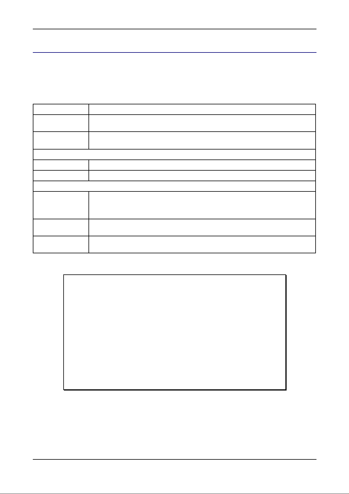
From this the requirements for soil improvements and amelioration are outlined:
Site Selection
Once the soil has been ameliorated and improved, then the altered soil properties are considered in
conj unction with the topography, irri gati on system and crop types to delineate irrigation management units.
© Sentek Pty Ltd Page 9
Page 13

Site Selection
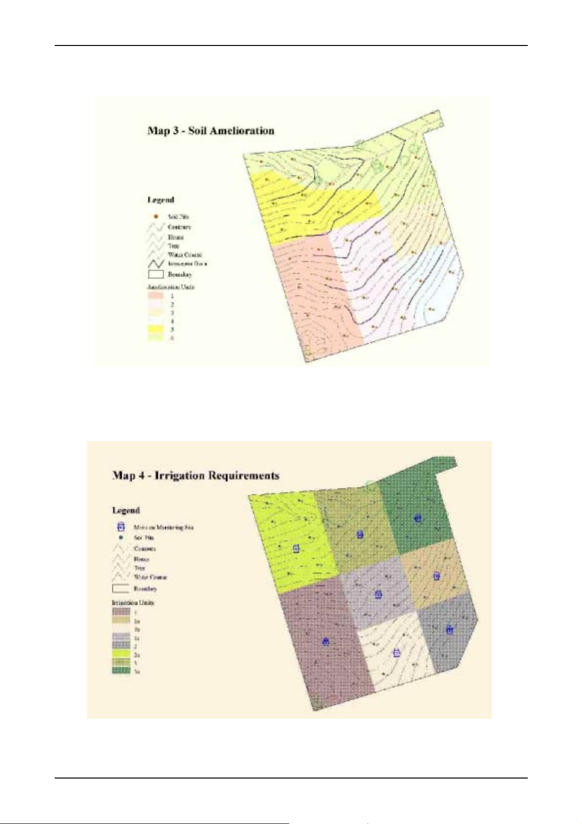
Overlaying all this information makes it possible to identify, wi thin a property, areas (zones) that have
si gnificantly different requirements.
In the example used, the property has been divided into eight macro zones. Each m acro zone requires a
monitoring si te. Potential sites are shown by the dots, but final posi tioni ng can be determined by the
information in the micro scale zone sel ection.
Micro scale zone selection
With macro zone selection you have identi fied the i rrigation management units on your property. Micro scale
zone selection is used to target the actual site of the access tube in relation to crop, micro-scale soil
var iability and ir r iga tion deliver y point.
Note: Micro zone selection is equally as important as macro zone selection and
has a direct effect on the representati ve value of the data.
In soil-based monitoring the measurements are taken from a small part of the root zone. Sentek sensors
record the dynamics of m oisture i n the part of the soil profile where the access tube has been installed. If
you miss the root system or install the access tube i n dry or wet irrigation spots, the data wi ll not make sense
and cannot be used for irrigation scheduling, as it will not be representati ve of an entire i rrigation
management unit.
So il moisture m onitorin g ins t r um ents are of t en bl a med if there is no inc rease in moistur e c ontent aft er a n
irrigation, but testing will al most always show that the si ting of the equipment i s wrong. For example i t is
common to fi nd that the access tube is placed in a dry spot, cause by a sprinkler system havi ng a poor
distribution uniform ity. Also, on slopi ng ground, the lateral movem ent of water needs to be taken into
consideration when si ting the access tube.
Where there are variations in the micro relief or soil properties and depth over very small distances that
affect the root di stribution and growth of the plant (e.g. in gilgai soils), it may be necessary to i nstall more
than one soil moisture probe in the same area to represent these variations.
Micro zone selection gui delines
Followi ng i s a set of guidel ines for selecti ng access tube i nstallation sites within irrigati on m anagement units.
Thre e ma jor fac t or s need to be taken in to ac co unt; irr ig ation, pl ant health and s oi l type.
Irrigation sy ste m
It is important to check that your irrigation system is performing as per the design specifi cations prior to
installation. Variations in sprinkler pressure and flow, pump performance, distribution uniformity and wind
can result i n uneven patterns of watering and irrigation depths. This can lead to salinity problems,
development of water tables, water logging, root death and an overall decline in crop health, yield and
quali ty.
Before you commence irrigation scheduling make sure your irrigation system performance is at an
acceptable level. Read the recommended l iterature (Merriam & Keller, 1978) to perform detailed checks on
irrigation systems or contact your irrigation consultant or Department of Agriculture for further advice. It is
important to check your i rrigation system at least once a year.
Conducting a distribution uniformity (DU) test
Prior to installing the site, it is also necessary to check the distribution uniformity of the system. The
uniformity of water distribution from sprinkl ers can be checked with a simple can test. The method involves
arrangi ng cans in a grid pattern withi n the wetted area and measuring the volume of water i n each can.
© Sentek Pty Ltd Page 10
Page 14
Site Selection
In the example illustrated below, cans in the blue shaded area received above average water; those in the
red shading below average; while those in the green shaded area received an average amount.
Due to the specific nature of each site in terms of irrigation system, it is inappropriate to give prescriptive
adv ic e on tu be pl ac e me nt. For soil mo is tur e mo ni tor i ng, tu be placement s hou ld how ever, be re pr esenta t iv e
and consistent of the area being watered. General guidelines for commonl y used systems and principles of
sample site sel ection fol l ow.
For sprinkler systems, it is preferable to use two access tubes per site, placing one into an area receiving
average precipitation and the other one into a wet or dry spot, depending on a soil salinity or water table
problem.
In centre pivots, if the distribution uniformity tests show si gnificant variation between booms, two or more
access tubes should be installed, with at l east one tube in each different area. For high pressure rain guns,
measure the water application pattern under di fferent wind conditions to ensure that you don’t pick on area of
extremely l ow or high water application.
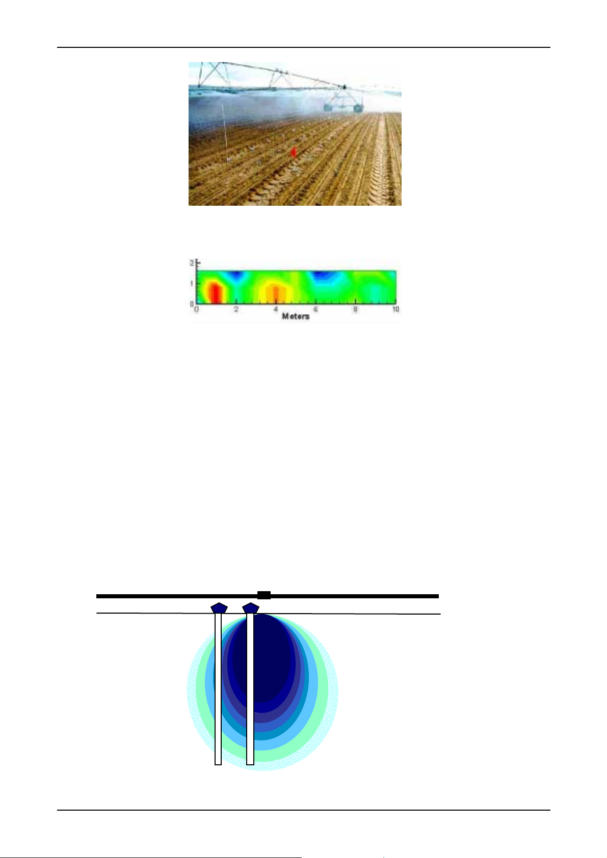
Installation of probes in drip irrigated crops needs consideration of the extent of the ‘wetting onion.’ Use at
least two probes to moni tor soil moisture of drip irrigated crops to measure both the vertical and the lateral
spread of water. The schematic below shows an example of the variation i n the wetting pattern below a
dripper. The darker blue colour signi fies wetter soil conditions, while the lighter blue colour signifi es drier soil
condi tions. The pl ant roots will utilize the water from di fferent locations under the dripper at different
intervals; therefore it is very important to measure these differences using more than one probe.
© Sentek Pty Ltd Page 11
Page 15

Site Selection
In addition, in drip irrigation, the slope needs to be taken into consideration, to account for movement of
wate r do wn slop e.
In furrow irrigated fields, access tubes should be installed 50 to 100 metres away from the head ditch.
Access tubes should not be installed solely at the opposite side to the head ditch, as tail water from the
irrigation may back up the furrows and give unrepresentative readings. Placement of tubes here may be
considered when measurement of deep percolation below an irrigation field is required. Consideration
should also be given to placing another tube in the middle of the field to measure the depth of irrigation
there.
Plant h ealth
Select a site next to an average-sized, heal thy plant representing the Irrigation management unit. Avoid:
• Stunted or sick plants
• Unusual ly l ar ge p lan ts or trees
• Spots where plants are missing
General guidelines for key crops include:
• In fi eld crop and vegetable production, choose a uniform crop stand, and ensure that the
probes are inserted within the actively growing root zone.
• In orchards, use two access tubes to monitor the site. Place one access tube under the
canopy of the trees and another outsi de the canopy – there will be some interception of rainfall
by the canopy so less rain water will penetrate the ground directly under the canopy. Select a
si te that represents dynamic data trends (more root activity) and again consi der irrigation
dist r ibu tion unif ormity.
Soil p roperties
Soil properties influence probe placement in drip irrigati on, as the wetti ng pattern is highl y dependent upon
the soil. In uni form sands, most of the water applied under the dri pper will tend to move vertically through
the profile, with minimal lateral spread. Conversely, i n uniform clay soils, the water will tend to spread
laterally as well as vertically. In soils of contrasting textures, there will be varyi ng wetting patterns that need
to be taken into consideration.
In many soils there are substantial variati ons in the thickness of horizons and in the potenti al rooting depth.
This can lead to si gnificant variations in soil water storage capaci ty and plant growth over relatively short
distances. Under these conditions, it is recomm ended to install to two access tubes to ensure that this
variability is taken into accou n t.
Other micro zone selection considerations
There are several other factors when considering micro zone selecti on that also need to be taken into
consideration. These are:
• Do not install access tubes in outsi de rows. These locations are usually exposed to wind and
dust, particularly in the vicinity of roads or adjoining broad-acre properties.
• Avoi d the ‘drip ring’ in, for example, citrus orchards, where sprinkler irrigation water is
channeled by the canopy to the outside bottom edge of the foliage creating wetter soil
condi tions at the edge of the canopy.
• Avoi d wheel tracks (and wheel track rows) as the soil is more compacted in these areas and
stores less readily available water than the rest of the field (non wheel track rows).
© Sentek Pty Ltd Page 12
Page 16

I nstalling EnviroSCAN, Enviro SMART & Diviner 2000 access t ub es
Installing access tu b es for Divin er 2000, EnviroS C AN and
EnviroSMART probes
Introduction
It is ne cessary to install Sentek access tubes before Sentek sensors can be used to measure vol umetric soil
water content. Access tubes are installed at sel ected sites usi ng Sentek instal lation tools. The tools are
specific to the installation method so it i s important to understand the installati on method before purchasing
your installation tools. A slurry installation method may be used for soil with a high gravel and stone content.
Note:
Inspect the soil types on your property prior to undertaking an installation to
ensure that you have the correct tools. The standard installation kit is designed for
installation i n most soi l types, but in some situations such as very heavy clay or
roc ky soils, additional tools may be require d.
Once you have i dentified your soil properties, read the rel evant section of this
manual to determine what tools you require.
If yo u ar e unsure about any aspect of t he i nstalla t ion m et h od, c on tac t y our Sen tek
reseller and discuss the sites you have selected and your installation needs.
The aim of the installation process is to cause minimum disturbance to the surroundi ng crops and soil profile.
Disturbances to the soil may introduce pockets of air and loosely packed soil material. The disturbances
affect the contact of the outer surface of the access tube wi th the surrounding soil profile and may lead to
preferential flow of irrigation water or rain to a greater depth compared with the rest of the field. If readings
are taken under disturbed soil conditions they m ay by i ncorrect or misleadi ng.
Warning:
Access tubes must be installed so that they fit tightly in the soil along their entire
length. Permanent errors can be introduced into the readings through poor or
hasty installations. Any air gaps between the length of the access tube and the soil
will cause data deviations.
For exa mp le , the penet r at i on de pt h of an ir r i ga ti on appear s to be m uc h de eper if
there is an air gap next to the access tube. This misrepresents the depth of the
irrigation in the field at that site.
The addition time taken i n careful installati on ensures access to accurate and
me an in gfu l dat a.
© Sentek Pty Ltd Page 13
Page 17

I nstalling EnviroSCAN, Enviro SMART & Diviner 2000 access t ub es
Disclaimer:
The access tubes, probes and sensors supplied by Sentek are speci fically
desi gned to be used together. Other brands of probe and access tube are not
compati ble with the Sentek products and should not be used as they may damage
Sentek equipm en t thro ug h inco rrect use a nd will invalida te warranty agreement s.
Sentek has developed precision i nstallation tools to be used for the installation of
Sentek access tubes. The precisi on of the access tubes and tools is designed to
complement the high value of readings taken by the Sentek sensors. T his value of
both relative and absolute readings is compromised when poor and hasty
installation methods are used.
Safety
Sentek encourages the use of safe practices that minimize the risk to users, their machinery and their
property. The following safety information i s provided to help you prevent acci dents on your property.
Carrying equip ment into th e field
An access tube installation requires access tube kits, toolkits, miscell aneous tools and duck boards. Often
yo u can not drive a vehi cl e al ongsi de the installation si te so it is i mpo rtant to conside r ho w y ou will ge t the
required equipment to the site.
The toolkits come i n cases that protect them from the elements and from general damage. T hese ki ts have
handles to help you carry them into the field. It is important to carry the longer kits in a way that does not
place undue stress on your body nor damage crops.
When carrying equipment into the field remember to:
• Bend your knees and keep your back straight when lifting
• Make several small trips rather th an trying to carry too much at one time
Wor k ing with in sta lla tio n e quipm e nt
It is important that you wear gloves and safety goggles to protect your hands from burns and to prevent your
eyes from penetration injuries caused by splinters of metal or soil.
When using motors to drive augers, ensure you wear ear protectors to minimize the affects of the motor on
your hearing.
Protect ing and caring for equipment
There are numerous items in the various toolkits. It is important to keep all of the items clean and to put
the m away in the ir pr otectiv e cas es when not in use.
Good versus poor installation
The aim of any installati on i s to cause as little disruption to the normal soil structure as possi ble, and provide
an envi ronment where the soil moi sture may be detected repeatedly and accurately over an extended period
of time.
If the surrounding soil is disturbed during the installation process, then air gaps m ay form down the side of
the tube, which can lead to preferential flow of water between the soil and the access tube. Water will travel
dee per t han in the s ur r ound in g s oi l, lea di ng t o a mis l ea di ng r e pr esent at ion of wat er mov emen t in the soil.
© Sentek Pty Ltd Page 14
Page 18
I nstalling EnviroSCAN, Enviro SMART & Diviner 2000 access t ub es
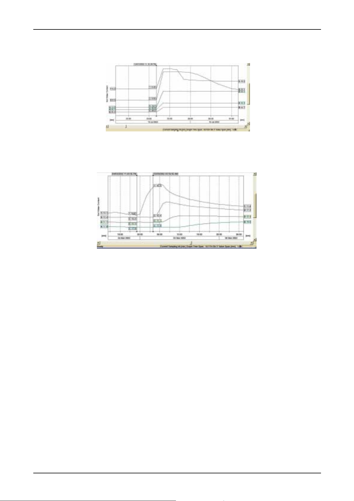
The figure below shows preferential flow of water down the side of the access tube, where the wetting front
moves to the bottom sensor almost instantaneously.
The movement of wetting front should match the hydraulic properties of the soil, such as shown in the
exa mp le be l ow .
© Sentek Pty Ltd Page 15
Page 19

I nstalling EnviroSCAN, Enviro SMART & Diviner 2000 access t ub es
S tandard manual inst al l ation method
Introduction
The Standard manual installation method is recommended for most soil types. In this method the access
tube hole is hand augered into the soil, through and slightly ahead of the access tube. This i s done using the
47.0 mm Regular Auger. The augered hole is slightly smaller than the access tube. The access tube is
fitted with a cutting edge that cuts the l ast of the soil away, providing a ti ght fit down the length of the access
tube.
This method prevents the formation of air pockets along the length of the access tube and causes minimum
disturbance to the surrounding soil profile. Thi s installation method is proven to be the most reliable and
provides the best soil moisture data.
Items required for standard manual installations
Sentek has developed a set of installation tools specifically for the installati on of their access tubes. An
inst allation requires:
• Sentek access tube item s
• Sentek toolk its
• Miscellaneous items
Each toolkit comes in a protective carry case. Items that look similar are marked with their measurements for
easy identification. Protective tubes are included to encase augers and other sharp tools. This protects
them in transit and prevents damage to the tool bag.
All tools requi red for the Standard manual installation method are contained in the Standard Access Tube
Installation Kit Complete. The tools are supplied in two carry bags.
Read through the installation method to identify the tools, cutting edges and bottom stoppers you will need
and ensure you have those tools before proceeding to the installation site.
Sentek access tube it ems
Item Part Number
Div iner 2000
Access Tube Ki ts at ordered
lengths (includes Access
Tubes, Cutting Edges, Top
Cap Assemblies and
Expandable Bungs)
EnviroSCAN & Envi roSMART
Access tubes at ordered
lengths
Cutting edges
Top cap assembly complete
Expandable bungs
11720, 11700, 11710
20510, 21010, 21510, 22010
80035, 80040
22400
22455
© Sentek Pty Ltd Page 16
Page 20

I nstalling EnviroSCAN, Enviro SMART & Diviner 2000 access t ub es
Toolkit items
Item Part Number
Sta ndard Acce ss Tube Ins tallation Toolkit Complete
Part A – Auger Kit, includes:
1 x Regular Auger 47.0 mm
1 x Regular (clay) Auger 53.0 mm
2 x Auger Extension Rods (0.5 m)
1 x Auger Extension Rod (1.0 m)
1 x Regular T -handle
2 x Tommy bars
1 x Access tube rag cleaning tool
1 x Access tube brush cleaning tool
1 x Access tube bailer
1 x Expandable bung tightening tool
1 x Extraction tool
1 x Toolbag No. 1
Part B – Tripod Kit, i ncludes:
1 x Access tube installati on tripod
3 x Tripod anchor pins
1 x Base plate
1 x Auger centralisation pol y guide
07050
07000
70135
70140
70125
70130
70150
70190
70110
70112
70195
70160
70305
70100
07150
70230
70215
70220
70225
© Sentek Pty Ltd Page 17
Page 21

I nstalling EnviroSCAN, Enviro SMART & Diviner 2000 access t ub es
1 x Ny lon dolly
1 x Heavy duty dolly
1 x Toolbag No. 3
M is c ellan e ous ite ms (ins taller t o sup ply)
• A le ngth of rope – to tie branches or vines tem porarily out of the way so that they do not get
damaged or i nterfere with the augering process
• A se t of duck boards – to prevent soi l compaction around the access tube during the
installation process
• 1 x sledge ham m er – to drive the access tubes i nto the soil. A 3-4 kg (8-10 lb) hammer is
recommended.
• 1 x meas uring tape – to measure the required depth
• 1 x marki ng pen
• 1 x 10 litre (2 gallon) bucket – to collect the augered soil and remove it from the site
• 1 x flashlight (torch) – to inspect the inside wal ls of the access tubes after the cleaning
process
• 1 x notepad and pencil – to record the depth and texture variation throughout the soil profile
and any other site information
• Methylated spirits – to moi sten the cloth used with the access tube rag cleaning tool to
remove possibl e water and mud from the walls of the access tube, if required.
• Cotton cleaning cl oths – to clean the inside of the access tubes and other tools after
installation.
• Silicon glue – to seal the base of the top cap to the top of the access tube.
70205
70210
70300
Installation procedure
Step 1 – Preparing the sit e
In all installati ons, disturbance to the surrounding crops and soil profiles must be minimized because soil
compaction alters the capacity of the soil to absorb water.
1. Use duckboards at the site
2. Use ropes to tie crops out of the way if necessary
Step 2 – Assembling the tripod
The tri pod keeps the auger in a stationary central position and prevents di sturbance to the surrounding soil
through ‘wear out’ or hole enl argement. It also stabilises the access tube during the installati on process by
stopping the access tube from flexing at the point where the access tube enters the soil each time i t absorbs
a hammer blow. This prevents air gaps from forming along the side of the access tube.
Warning:
This tripod must be used to ensure a sound installation using the standard
‘through the access tube drilling method.’ Any air gaps between the access tube
and the soil will give false readings.
© Sentek Pty Ltd Page 18
Page 22

I nstalling EnviroSCAN, Enviro SMART & Diviner 2000 access t ub es
To assemble the tripo d at the site:
1. Attach the base plate to the base of the tripod.
2. Centre the access tube installation tripod over the site where the access tube is to be
installed.
3. Loosen the wing nuts and spread the legs of the tripod until the base plate touches the
gr oun d and the low er le gs are pro tr udin g approx i mat e ly 5 cm (2 inches ) out of t he up per le g
sections. Note: The legs of the tripod can be adjusted for a straight access tube i nstallation
on sl opi ng ground or on top of m ounds.
4. Secure the tripod i n position by driving the tripod pins through the holes in the foot of each
leg into the soil using a sledge hammer. Note: Ensure the pin head touches the foot plate to
ensure the feet of the tripod legs don’t move during installation.
5. Check that all the wing nuts are loose. Insert the sledge hammer handl e into the tri pod
cylinder and straighten the tri pod by moving the tripod cylinder into a vertical position.
© Sentek Pty Ltd Page 19
Page 23

I nstalling EnviroSCAN, Enviro SMART & Diviner 2000 access t ub es
Watch the bubble in the spirit level on the side of the tripod. Move the handle around until
the bubble is located in the centre of the level window.
6. When the tripod cylinder is in a vertical position, firmly tighten the wing nuts of the legs.
S tep 3 – In s talling th e a c c e s s tube
Access tubes are supplied with 50 cm (20 inches) of extra length to accommodate at least one bottom
stopper. In sites severely affected by a water table, two bottom stoppers may be used.
To install the access tube
1. Put on gl oves to protect your hands and increase your ability to gri p the equipment.
2. Put on safety goggles to protect your eyes from metal splinters, which may dislodge from the
inst allation dolly on hamme r impac t.
3. Select the yellow metal cutting ed g e. Tu rn the cutting edge on its sid e and, with a twi sti ng
motion, shave a layer of PVC from the lip of the access tube. Carefully bounce the access
tube and the partially fitted cutting edge on the si de of the sl edgehammer head until the
cutting edge fits squarely onto the end of the access tube.
© Sentek Pty Ltd Page 20
Page 24

I nstalling EnviroSCAN, Enviro SMART & Diviner 2000 access t ub es
4. Select the 47.0 mm regular auger head. Note: This auger is designed for all soils and
should be used where possibl e, even in heavy textured soils, as it provides the best
possibl e access tube installation method. The other augers are used to take over when you
run into probl ems. See the Troubleshooting Section for further information.
5. Select the required extension rods and screw the au ger hea d an d T-handle to the extension
rods.
Note: To add extra extension tubes to an existing auger assembl y,
place the auger on the ground. Insert the Tommy bar into the hole of
the ext e nsion tu be be l ow th e T-Handle. Loosen the extension rod from
the T-handle using one quick jerk of the T ommy bar. When loose,
remove the Tommy bar and unscrew these two parts until separated.
Screw the additional extension(s) onto the exi sting auger extension and
refit the T-Handle.
6. The total length of the auger should be a minimum of 20 cm longer than the access tube.
Push the auger through the access tube until the auger head protrudes by 20 cm. Use the
marking pen to mark the auger extension rod at the point where i t disappears into the top of
the access tube. This mark is later used to show the depth to which to auger.
© Sentek Pty Ltd Page 21
Page 25

I nstalling EnviroSCAN, Enviro SMART & Diviner 2000 access t ub es
7. Disengage the metal “tooth” on the tripod by turning the lever located on the tripod cylinder.
The metal “tooth” is designed to prevent the access tube from spinni ng during augering, and
should not be engaged while hammering in the access tube.
8. Insert the access tube with fitted cutting edge into the tripod guide tube, with c utting edge
facing downwards.
9. Select the H eavy du ty dolly and insert it i nto the top of the access tu be.
10. Use the sledge hammer to tap the dolly until the access tube is embedded approximately 510 cm (2-4 inches) i n to the soil.
11. Place the auger inside the a ccess tube and turn the auger handle clockwise to remove the
soi l from inside the access tube. Continue to auger ahead of the access tube by
approximately 20 cm (8 inches). Use the pen mark on the rod to indicate when the desired
© Sentek Pty Ltd Page 22
Page 26

I nstalling EnviroSCAN, Enviro SMART & Diviner 2000 access t ub es
depth has been reached. Note: If the access tube spins while augering, engage the meta l
“tooth” on the tripod by turning the lever located on the tripod cylinder.
12. Use the auger cleaning tool to remove the soil from the auger head. Do not empty the
augered soil near the access tube as it may change the infiltration rate of irrigation and
rainfall . Dispose o f the so il away from the monitorin g site.
13. Sel ect the Heav y dut y dolly and re-insert it in the top of the access tube.
14. Turn the lever to make sure that the meta l tooth on the tri pod cylinder is “disengaged”. T ake
the sledge hammer and hit the dolly to drive the access tube further into the pre-drilled hole.
15. When you reach the bottom of the pre-drilled hole, hammering becomes noticeably more
difficult. Re m ove the do lly .
© Sentek Pty Ltd Page 23
Page 27

I nstalling EnviroSCAN, Enviro SMART & Diviner 2000 access t ub es
16. Auger ahead of the access tube by approximately 10 – 20 cm (4 – 8 inches). Alternate
between augering and ham mering until the dolly resting on top of the access tube nearly
touches the top of the tripod.
17. Insert the yello w Nylon dolly (which has the same diameter as the access tube) into the
access tube and continue hammering and augeri ng until the mark on the dolly is l evel with
the top of the trip od.
Note: Installing the access tube to this depth will enable the ba se of the
top cap to sit flush with the ground. T his will position the middle of the
first sensor at 10 cm below the ground surface. Som etimes i t may be
desi rable to posi tion the first sensor 5 cm below the ground surface. If
this is the case, only hammer in the yellow ny l on do l ly until the mark on
the dolly is 5 cm above the top of the tripod.
18. Auger out the remaining soil from insi de the access tube.
19. Remove the tripod pins by insert ing t h e Tommy bars into the holes of the tripod pins and
pu lli ng them upwards with a twis t ing motio n.
© Sentek Pty Ltd Page 24
Page 28

I nstalling EnviroSCAN, Enviro SMART & Diviner 2000 access t ub es
20. When all pins are removed, carefully lift the tri pod straight upward and off the access tube.
21. Try twisting and moving the tube backwards and forwards while examining the surface soil
surrounding the access tube. The tube should not m ove and there should be no visible air
gaps.
22. If there is an air gap, retri eve the access tube and start the installation process again at a
site that is at least on e metre away from the failed installa tion.
Note: Clean the tools and return them to the case after use to ensure they are not
lost or damaged.
© Sentek Pty Ltd Page 25
Page 29

I nstalling EnviroSCAN, Enviro SMART & Diviner 2000 access t ub es
St ep 4 – Cleaning t he access tube
The access tube must be cleaned before the top cap is installed and readings are taken. The bottom
stopper i s installed after cleaning in all soils, except for very wet and saturated soils. In these soi l s it is
in stalled first to prevent the rise of wate r into the tube during cleaning.
To clean th e tube
1. Installing an access tube in most soil types leaves a thin layer of soil coating on the inside
wall.
2. Detach the au ger head and attach the Access Tube Nylon Brush Cleaning Tool to the auger
extension. Plunge it up and down the access tube using a rotating acti on. T he brush tool
wil l d is lod ge any s oil coatings.
3. Select the Access Tube Rag Cleaning Tool. Fold the cleaning tool to i ts full length and
s ec ur e it by s l id in g t he locking br ac ket int o p l ac e.
4. Insert a clean cotton cloth into the eyelet and saturate it with methylated spirits.
5. Insert the cotton cloth and move the tool up and down the access tube to clean any
remaining soil particles from the wall of the access tube. The methylated spirits will also
acc e ler at e the dr y i ng pr ocess on th e ins id e of t he tub e if the rem ov e d soil is w et.
© Sentek Pty Ltd Page 26
Page 30

I nstalling EnviroSCAN, Enviro SMART & Diviner 2000 access t ub es
6. Change cotton cloths as required and continue with the cleani ng action until inspection with
a flashlight (torch) shows that the access tube is clean and dry.
7. Note: In sandy soils, it m ay not be necessary to use the nyl on br ush to ol as the access tube
can be easily c le aned w ith the rag tool. An alternative is to use a f oam cle aning tool, which
is avai lable as an Optional Extra (refer to section on Toolkit Items).
S tep 5 – In s talling the bott om sto ppe r bung
The bottom stopper bung is installed after the access tube has been cleaned in all soil conditions, except for
in very wet and saturated soils. In these conditions, the bottom stopper bung is installed prior to cleaning.
To ins tall t he bo t t om st o ppe r bung
1. Ensure the access tube is clean before proceeding.
2. P artially insert t he expandable bu ng i nto the access tube and hold it at the upper end so that
about 75% of the top rubber ri ng i s withi n the access tube.
3. Tighten the wing nut to the point where there is enough fri ction on the wall of the access
tube to prevent the bung from turning in the tube while the wing nut is tightened. Note: Do
not tighten the bung t oo much as air will be un able to move past the bun g and will ma ke it
hard or impossibl e to push to the bottom of the access tube.
4. Attach the Expandabl e Bung Tightening Tool to the auger extensi on rod and use the tommy
bars to tighte n it f irmly to the extensi on rods.
Caution:
Failure to tighten this tool securely may resul t in the tool loosening,
coming off the extension rod and landing i n the bottom of the access
tube.
© Sentek Pty Ltd Page 27
Page 31

I nstalling EnviroSCAN, Enviro SMART & Diviner 2000 access t ub es
5. Place the Expandable Bung T ightening Tool over the wi ng nut and slowly push the bung
down the access tube. Allow ai r to escape until the bung rests on top of the internal cutting
edg e o n t he inside of the tube.
6. Sl owly tur n the T-Handle until you feel you firm resi stance to further turning. Note: The
bottom stopper bung is designed to run out of thread while tightening. This prevents over-
tightening whi ch could cause damage to the walls of the access tube.
7. When the bung is sitting tight, twist the tool clockwise quickly while pulling upwards. This
will release the spring on the tool from the wi ng nut and enable you to pull the tool out of the
access tube.
Warning:
A watertight installation of the bottom stopper bung is essential to
prevent m oisture and free water entering the access tube. Water inside
the access tube will distort soil moisture readings and damage electronic
circuitry.
In soils with water tables, it may be necessary to use two bottom
stoppers to ensure a totally water tight installation.
S tep 6 – In s talling th e top c a p
The top cap assem bly i s installed after the access tube has been cleaned and the bottom stopper fitted.
To install the top cap
1. Make sure the 4 cm (1.6 inches) of access tube protruding from the soil is clean inside and
out.
© Sentek Pty Ltd Page 28
Page 32

I nstalling EnviroSCAN, Enviro SMART & Diviner 2000 access t ub es
2. Take a si licon gun with a new nozzle and apply three rings of silicon around the outside of
the access tube, approximatel y 1 cm (0.4 inch) below the top rim of the tube.
3. Unscrew the cap from the top cap assem bly base.
4. For EnviroSCAN an d Envi roSMART applications, feed the cable through the Fai rRite bead
and then through the ca b le gland.
5. Take the top cap base and slowly push it onto the top of the access tube wi th a slight
forward and backward rotating motion until the bottom foot of the top cap touches the
undisturbed soil surface. T his wil l di stribute the si licone evenly.
Note: Ensure that no soil, grass or other material is present between the
top cap and access tube, as this can provi de pathways for water
movement through the silicon and into the top cap.
6. For EnviroSCAN an d Envi roSMART installati ons, ensure that the cabl e glan d is pointi ng in
the direction that the cable i s to be laid.
7. Wipe off any excess silicon from inside the access tube.
© Sentek Pty Ltd Page 29
Page 33

I nstalling EnviroSCAN, Enviro SMART & Diviner 2000 access t ub es
8. For EnviroSCAN an d Envi roSMART probes, strip back the outer sheath of the cable until the
end of the outer sheath sits just inside the cable gland. Fill around the wires inside the end
of the cable sheath with silicone to prevent moisture from travelling along the cable into the
top cap. Insert the electronics and connect the cable to the probe interface. For further
details on wiring of probes refer to the EnviroSCAN and EnviroSMART hardware manuals.
Posi tion a dry silic a gel bag on top of the electronics.
9. Screw the top cap back onto the top cap housi ng. For EnviroSCAN and EnviroSMART
probes, tighten the FairRite Bead on the cabl e next to the top cap.
Troubleshooting the standard manual installation method
The f oll ow i ng a lter n ative acc ess tube insta l lat i on t ec h n iqu es may be used wh en t he Standar d ma nual
installation method proves unsuccessful.
Read the description of the problem and its solution. Select the solution that best fits your situation before
trying the method. Alternative tools are available to assi st in difficult installations and can be purchased
separatel y as optional items (refer to section on Toolkit Items).
M ois t and s tick y he a vy clay s oils
Under moist and sticky, heavy clay conditions, the standard method of augering through the access tube and
hammering in the access tube may be too strenuous using the 47.0 mm regul ar auger. If thi s is the case,
us e the fo l lowin g install ation meth od.
To install access tubes in moist and sticky heavy clay soils
1. Ensure the tripod i s set up correctly and centred over the instal lation si te.
2. Select the 53 mm Clay auger and the required extension rods.
3. Fit the Auger Stabilisation Poly Guide over the extension rods and attach the T-Handle.
4. Put on gl oves and safety goggles to protect your hands and eyes from damage.
© Sentek Pty Ltd Page 30
Page 34

I nstalling EnviroSCAN, Enviro SMART & Diviner 2000 access t ub es
5. Insert the assembled auger into the tripod ensuring the centralization poly guide is fitt ed to
the top of the tripod cylinder.
6. Turn the auger 4-5 turns and lift i t gently approximately five centimetres, then turn the auger
another 3-4 turns. The lifting action moves the soil upward, partially filling the space around
the auger head and providing a greater uptake for additional soil. Note: Do not try to auger
too muc h s oi l at on e tim e, as the au ger may ov er - fi l l with s oi l, mak in g it d iffic u lt to r e m ov e
from the hole.
7. Clean the auger head and repeat the process to the required depth of installation.
8. When augering is complete, check the final depth with a measuring tape to ensure that you
have enough depth for your tube length. To posi tion the middle of the fi rst sensor at 10 cm
below the ground surface, ensure that 4 cm of access tube is protruding above the ground.
9. Ensure the yellow metal cut ting edge is fitted sq uarely onto the access tube.
10. Place the access tube fitted with cutting edge i n the tripod guide and insert the heavy du t y
dolly into the top of the access tube.
11. To prevent the access tube from flexing, attach extension rods to the Heavy Dut y Dolly,
ensuring they are firmly tightened.
12. Drive the access tube into the ground usi ng the sledge hammer. If the driving of the access
tube becomes too strenuous, use the 47 mm regular auger to clean out the soil shavings
repeatedly from the inside of the access tube. Continue hammering until you have reached
the fi na l de pth.
Dry an d heavy clay so il
For dry and heavy clay soils the Dry Clay 56.0 mm auger (available from Sentek as an accessory item) is
used as it cuts only 0.5 mm sm aller than the outside diameter of the access tube. T his reduces the friction
when drivi ng i nto the access tube. The red cutting edge with a longer neck is used for better stabilization.
To install access tubes into dry and heavy clay soils
1. Ensure the tripod i s set up correctly and centred over the access tube installation site.
2. Select the Dry Clay 56.0 mm auger and the required extension rods. Attach the auger head
to the extensi on rods.
© Sentek Pty Ltd Page 31
Page 35

I nstalling EnviroSCAN, Enviro SMART & Diviner 2000 access t ub es
3. Fit the A uger Cen traliz ati on Pol y Guide over the ex tens io n a nd attach the T-Handle.
4. Put gloves and safety goggles on to protect your hands and eyes from damage.
5. Insert the assembled auger into the tripod ensuring the centralizati on poly guide i s fitted to
the top of the tripod cylinder.
6. Turn the auger 4-5 turns and lift i t gently approximately five centimetres, then turn the auger
another 3-4 turns. The lifting action moves the soil upward, partially filling the space around
the au ger hea d and pr ovid in g a gr e ater uptak e for additiona l soil . Note: Do not try to auger
too muc h s oi l at on e tim e, as the au ger may ov er - fi l l with s oi l, mak in g it d iffic u lt to r e m ov e
from the hole.
7. Clean the auger head then repeat the process to the required depth of i nstallation.
Hint:
If the augering becomes too difficult, attach the Heavy Duty T -Handle
and reinforced extension rods, and gentl y tap the top of the T-Handle
with the sledge hammer between auger turns to assi st the auger in
“biti ng” into the so il .
8. When augering is complete, check the final depth with a measuring tape to ensure you have
enough depth for your tube length. To position the middle of the first sensor at 10 cm below
the ground surface, ensure that 4 cm of access tube is protruding above the ground.
9. Fit the red metal cuttin g edge squarel y onto the access tube.
10. Place the access tube fitted with cutting edge i n the tripod guide and insert the He avy Duty
Dolly into the top of the access tube.
11. To prevent the access tube from flexing, attach extension rods to the Heavy Dut y Dolly,
ensuring they are firmly tightened.
12. Ensure you have safety goggles on and drive the access tube into the ground using the
sl edge hammer. If the dri ving of the access tube becomes too strenuous, use the 47 mm
r egu lar auger to clean out the soil shavings repeatedly from the inside of the access tube.
Continue hammer i ng unt i l you hav e r eache d t he fi nal de pt h.
© Sentek Pty Ltd Page 32
Page 36

I nstalling EnviroSCAN, Enviro SMART & Diviner 2000 access t ub es
Gravelly s oils
If you encounter a layer of small stones or gravel and the 47.0 mm regular auger i s unable to proceed, attach
the 47.0 mm Open Centre Tungsten Tip Auger. This auger is capable of breaking up and retri eving gravel of
up to thumbnail size under most conditions.
If you encounter larger stones, attach the 47.0 mm rockbreaker to the reinforced auger extension rod and fit
the Hea v y Dut y T-Handle. This will allow occasional large stones to be broken.
Under ver y dr y or w et co nd it io ns, you may ne ed to attach the Ac ces s Tube Spiral Cleaning To ol to remove
very dry and loose sand or gravel in liquid mud. When you have passed this obstacle you can continue
aug er i ng using th e Standard Manual Installation Method.
Ext remely dry an d loose san d
If you are installing access tubes into very dry and loose sand there could be problems with the augered
material falli ng out of the auger when you pull it out of the access tube. If this occurs use the Access Tu be
Spiral Cleaning Tool as the aug er i ng devic e. The on e- tur n me t a l s pir a l t oo l do es an exce llent job retr i eving
the ma teria l in th es e cond it i ons.
Water tables
On sites with a perched or shallow water table, water will enter the bottom of the access tube hole. Use the
acce ss tube bai le r to remove water and liquid mud between each augering. Lower the bailer i nto the bottom
of the access tube, wai t a few seconds for it to fill, then pull the bailer up and empty it into a bucket. You will
only be able to dig a certain distance into completely saturated soil, until conditions become too sloppy to
co nti nu e work. The bot tom sto pper will ne ed to be ready for immedia te insta llation after retri eving th e la st
auger load.
© Sentek Pty Ltd Page 33
Page 37

I nstalling EnviroSCAN, Enviro SMART & Diviner 2000 access t ub es
S tony Soils
The standard manual installati on method is not suitable for stony soi ls. If you know your soils are very
gravely and stony, the Slurry Installation Method must be used (see followi ng pages).
© Sentek Pty Ltd Page 34
Page 38

I nstalling EnviroSCAN, Enviro SMART & Diviner 2000 access t ub es
Slurry Installation Method
What are the dif ferent slurry methods?
The slurry installation methods are techniques used in soils with a hi gh stone and gravel content. Stony soils
are hard to auger and do not break up evenly. Large air pockets form easily when installing access tubes in
these soils, causing unrel iable readings.
Note:
The slurry methods are suggested for:
• Where the site soil has been tested and found to be high in stone and gravel content
• In access tube installations deeper than 2.5 – 3 m.
Warning:
Slurry installations are not recommended in sandy soils.
A sl ightly oversized hole is drilled and party filled with slurry. The slurry is a special mud mixture of kaolinite
and cem ent that is poured into the augered hole and fills the spaces where air would normally gather. The
access tube is pushed through the slurry and air bubbl es move up through the slurry and are released. As
the slurry dries, i ts moisture content balances with the moisture content of the surrounding soils.
Note: The equilibrium with the surrounding soil may not be 100%, however the
sphere of infl uence of the sensor penetrates the 5-10 mm slurry and measures the
soi l water content of the surrounding soil.
Although you are not m easuring the pure undisturbed soil with this installation method, Sentek experience
has shown that you can achi eve good sci entific study outcomes and commercial benefits usi ng this method.
Warning:
If you require absol ute data, Se ntek sensors need to be calibrated with the dried
sl urry in place, as described in the Sentek Calibration Manual.
Two drillin g me thods a re u sed for slurry installations:
• Manual slurry installation method – where a slightly oversi zed hole i s drilled into very stony and
gravelly soils using a hand auger
• Machine slurry installation method – where a slightly oversized hole is dri lled into very stony
and gravelly soils using a motorized auger.
The access tube installati on i s the same for both methods, which are described in detail bel ow.
Sentek has developed a set of installation tools specifically for manual slurry installations (Slu rry Acce ss
Tube Installation Kit).
An installation requires:
• Sentek access tube it ems
• Slurr y Access T ube Insta l lati o n Toolki t
Read through the installation method to identify the tools you will need and u ndersta nd thei r use. Ensure
that you have the tools you require before proceeding to the installation site.
© Sentek Pty Ltd Page 35
Page 39

I nstalling EnviroSCAN, Enviro SMART & Diviner 2000 access t ub es
Note: Slurry installations take some preparation time, and also sufficient time
needs to be allowed for the sl urry to dry and equilibrate with the surrounding soil
before the data can be used. Slurry installations should only be attempted in soils
where the standard installation method is not possibl e.
Items req u ired f or slurry in stallatio n s
Sentek access tu b e items
Item Part Number
Div iner 2000
Access Tube Ki ts, Slurry
(includes Access Tubes, Top Cap
Assemblies and Slurry Bottom
Stoppers)
EnviroSCAN & Envi roSMART
Access tubes at ordered lengths
Top cap assemblies – complete
Slurry bottom stoppers
11725, 11705, 11715
20510
22405
22206
Toolkit ite ms
Item Part Number
Slurry Access Tube Inst al la tion Kit ,
includes:
1 x Auger extensi on 0.5 m
1 x Auger extensi on 1.0 m
1 x Slurry auger 61.0 mm
1 x Heavy duty T -handle
2 x Tommy bars
5 kg bag of kaolin clay
1 x toolbag
07250
70125
70130
70148
70030
70190
80090
70400
© Sentek Pty Ltd Page 36
Page 40

I nstalling EnviroSCAN, Enviro SMART & Diviner 2000 access t ub es
Additional items for difficult stony soils
Item Part Number
Ope n Cen tr e Tu ngsten Ti p Auger 61.0 mm
Rock Breaker 54.0 mm
Auger extension rods re-enforced 1.0 m
70045
70025
70015
Mi sc ell an eous I tems (Installer to supply)
Length of rope – to tie branches or vi nes temporarily out of the way so that they do not get damaged or
interfere with the augering process.
Duck boards – to prevent soil campaction around the access tube during the installation process.
Measuring tape – to measure to the required depth
M ark ing pen
2 x 10 litre (2 gallon) buck ets – to coll e ct the augered soil and remove it from the si te , and to mix the sl u rry
in.
Notepa d and pencil - to record the depth and texture variation throughout the soil profile and any other site
information.
Paint stirrer with electric drill attachment – for mi xing the slurry.
Co r dl ess el ect r ic dril l – to attach to th e paint stirrer for m ixing the slu rry.
Spatula or br oad k ni fe – to chip aw ay excess sl urry
Sl u rry C omponents
Grey cement
Kaolinite (potters clay as fine powder)
Wa ter
© Sentek Pty Ltd Page 37
Page 41

I nstalling EnviroSCAN, Enviro SMART & Diviner 2000 access t ub es
Installation procedure
Step 1 – Glue in botto m stopp er
The slurry bottom stopper should be glued into the access tube prior to installation. Allow sufficient time for
the PVC g l ue to dr y .
To p r epare the access tube
1. Use PVC cleaning fluid to clean the bottom rim of the sl urry bottom stopper and the insi de of
the acc ess tube.
2. Use PVC glue and apply evenly to both surfaces.
3. Insert the slurry bottom stopper into the access tube and hold in place until the glue sets.
© Sentek Pty Ltd Page 38
Page 42

I nstalling EnviroSCAN, Enviro SMART & Diviner 2000 access t ub es
Ste p 2 – Auger the hole
To man ual ly au g er the acces s tube hol e
1. Select the required extension rods and screw the regular 61.0 mm (slurry) auger head and
T-handle to the extension rods.
Note: To add extra extension tubes to an existing auger assembl y,
place the auger on the ground. Place one foot on either side of the T-
Handle and insert the To mmy b ar into the hole of the extension tube
below the T-handle. Loosen the extension rod from the T-Handle us ing
one quick jerk of the Tommy bar. When loose, remove the Tommy bar
and unscrew these two parts until separated. Screw the additional
extensions onto the existi ng auger extensi on and then refit the T-
Handle.
2. Put on gl oves to increase your grip on the equipment and to protect your hands from heated
met a l w he n ins t a l ling on ho t d ay s .
3. Auger the hole to the required depth.
4. Insert the access tube with slurry bottom stopper fitted into the hole to check the depth level,
and then remove the access tube. The top of the access tube shoul d protrude out of the hole
by 4 cm (1.6 inches) for the top cap to sit flush with the ground. This will place the centre of
the first sensor 10 cm below the ground surface.
© Sentek Pty Ltd Page 39
Page 43

I nstalling EnviroSCAN, Enviro SMART & Diviner 2000 access t ub es
Hint:
If you encounter diffi culties augering through rocky or stony soils with
the regular 61.0 mm (slurry auger), use the Open Centre Tungsten Tip
Auger 61.0 mm or Rock Breaker 54 mm Auger. The Open Centre
Tungsten Tip Auger is capable of breaking up and retri eving gravel of
up to thumbnai l si ze. The 54 mm rock breaker will al low occasional
larger stones to be broken. The 54 mm rock breaker must be used wi th
the re-inforced T-Handle and auger extension rods.
If you still cannot auger a hole to the required depth, reposition the
auger in an alternative site, or use a motorized or mechanical auger to
drill the hole.
To drill the access tube hole using a motorized or mechanical auger
1. Select flight auger rods a nd attach a 61.0 mm tungsten tipped drill bit.
2. Attached the flight auger to a motor or drill rig assembl y.
3. Use gloves, ear protectors and safety goggles to auger the hole to the required depth.
Notes on using a handheld motor auger :
Getting the correct hole si ze in various soi ls using a flighted auger requires an understandi ng of what is
happening whi le digging. In moist clay soils (or any soil whi ch tends to adhere to the auger flight) the
procedure used will e ith er produc e too tigh t a ho le or a c orrec tly sized h ole.
No hole should be dug by going straight down, without lifti ng at intervals to clear the soil from the hole, or an
undersized hole may resul t. The tendency for the soil to re-adhere to the wall of the hole as i t moves up the
flight wi ll cause the hole to be undersized from the cutter size, m aking digging forces greater and the effort
required to li ft the auger out much ha rder.
To prevent this from happening, add a little water to the hole to “ease” the soil onto the flight each tim e the
auger motor starts to strain and the rotational force becomes hard to hold. Lifting the auger 150-200 mm
each time water is added wi ll greatly assist the clearance of the soil up the flight. Stop the rotation for a few
seconds each time water is added to the hole to allow time for i t to run down the flight to the digging point.
If the job is done correctly, the auger flight should be almost soil free when lifted from the hole. If not then
yo u ma y assume tha t too much so il ha s bee n re tained on the flight s and will tend to be f orced back on to th e
wall of the access hol e. T he walls of the hole should be moist and smooth, not rough.
Digging should be done by starting with a 0.5 or 1.0 metre auger flight. Add 0.5 metre extensions as
required.
Note: Sentek does not supply flight auger rods or mechanical augers, but can
refer customers to a suitable supplier if required.
© Sentek Pty Ltd Page 40
Page 44

I nstalling EnviroSCAN, Enviro SMART & Diviner 2000 access t ub es
St ep 3 – Ma ke t he s l urry
Sl u rry Recip e
• 1 part grey cement.
• 4 parts kaolinite (potters clay as fine powder).
• 5 parts wa ter
To mix the slurry on site, either take sufficient quantities of each slurry ingredient and suitable measuring
utensils to the si te or pre-mix the dry slurry i ngredients and store them in a plastic container.
1. Measure out 4 parts kaolinite and 1 part cement and mi x in a plastic container.
2. Slowly add water and stir with the paint stirrer until all the solids are com pletel y suspended in the
mixture. Ensure that no free water is separated from the solids and no dry lumps are l eft. The
consistency of the slurry should be similar to that of a milkshake. The slurry has a working life of
approximately two hours.
The quantity of slurry requi red will depend on the si ze of the access tube hole and the type of soil. The
diameter of the access tube hole will vary depending on the quanti ty o f st one pre sent.
© Sentek Pty Ltd Page 41
Page 45

I nstalling EnviroSCAN, Enviro SMART & Diviner 2000 access t ub es
Step 4 – Insert the access tub e
To install the access tube in the slurry mixture
1. Insert the sealed access tube into the augered hole. Note: At leas t 4 cm of extr a ac cess
tube must protrude from the hole for top cap fitting.
2. If more than 4 cm of tube is protruding and you cannot auger any deeper, mark the point 4
cm above the soil surface on the access tube wi th a marking pen.
3. Remove the access tube from the hole and cut off the excess access tube if necessary.
4. Pour the slurry into the hole until it fills approximately a third to half of the hol e.
5. Insert the sealed end of the access tube into the slurry.
6. Push the tube sl owly through the slurry allowi ng ai r bubbles to escape and the slurry to fl ow
out of the hole. Note: When installing access tubes longer than one metre, stop pushing the
tube into the hole when approximately 30 cm (1 ft) of tube is left above the hole. Wai t a few
minutes to let air escape before slo wly pu shing in the remainder of the tube.
7. If the access tube starts to float back up out of the sl urry, take two tent pegs and push them
into the soil approximately 50 cm (20 inches) away from either side of the access tube.
Stretch thin wire between the pegs and over the centre of the access tube to hold the tube in
place while the slurry dries.
8. Allow overflow slurry to dry for a few hours.
© Sentek Pty Ltd Page 42
Page 46

I nstalling EnviroSCAN, Enviro SMART & Diviner 2000 access t ub es
Step 5 – Chip off excess slurry
To tidy up around the access tube you may need to do one of the following:
• Take a spatula or broad kni fe and rem ove the excess dried slurry from the soil surface. A fine
white ring around the access tube, bridging the gap between the access tube and soil should
be visi b l e .
• If the slurry has settled and formed a depressi on in the soil, make up a small quanti ty of slurry
and fill any depressi ons back up to the level of the natural soil surface and leave it to dry, then
chip away any excess.
S tep 6 – In s talling th e top c a p
1. Make sure the 4 cm (1.6 inches) of access tube protruding out of the soil is clean on both
si des.
2. Take a si licone gun with a new nozzle and apply three rings of silicone around the outside of
the access tube about 1 cm (0.4 inch) below the top rim of the tube.
3. Unscrew the top cap from the base of the top cap assembly. For Envi roSCAN and
EnviroSMART in stallations, fe ed the cable through the Fa ir R it e be ad and then through the
cable gland int o t he top ca p.
4. Take the access tube top cap base and push it onto the top of the access tube with a slight
forward and backward rotating motion until the bottom foot of the access tube touches the
so il surf ace. T his will dist ribu te th e silicon e evenly . Note: For EnviroSCAN and
EnviroSMART applications, ensure that the cable gl and i s faci ng the direction that the cable
is to be laid.
5. Wipe off any excess silicone from the inside of the access tube.
© Sentek Pty Ltd Page 43
Page 47

I nstalling EnviroSCAN, Enviro SMART & Diviner 2000 access t ub es
6. Screw the cap back onto the top cap housing.
© Sentek Pty Ltd Page 44
Page 48

Removing acc ess tubes
Removing Access Tubes
Access tubes can be removed from a site when the site no longer requires monitoring. The access tubes,
top caps and bottom stoppers can be cleaned, stored and reused as required.
The access tube extraction tool can be used in conjunction with either the Sentek Extraction Tripod, or with
machinery with lifting capacity (e.g. jacks, winches or tractor hydraulics) to remove access tubes.
Items req u ired for access tube removal for EnviroSCAN, En viroSMART
and Diviner 2000
Item Part Number
Ex tra c tion Tools
Tube Extraction Tool
Sentek extraction tripod*
Ad d itional Tools
Expandable bung tightening
tool
Auger extensions
Regular T-handle
2 x Tommy bars
70305
70310
70160
70125 & 70310
70150
70190
*Note: machinery with lifting capaci ty such as j acks, winches or tractor hydraulics may be used instead of the
extraction tripod.
Additional ite ms
1 x small hammer – to tap the extraction tool into place in the access tube.
1 x hot air paint stripper - to remove si li con from the top cap.
Gloves a nd sa fe ty goggle s
Removing Envi roSCAN, En viroSMART and Divi ner 2000 Access Tubes
St ep 1 – Re mov i ng th e Bottom S top pe r
1. Unscrew the top cap from the access tube
2. Remove the EnviroSCAN or En viroSMART probe from the access tube, and ca r eful ly place on a
cle an dr y s ur f ace.
3. Attach the Regular T-Han dle and Ex pa nd able bung ti ghten ing t oo l t o the required auger extension
rods.
© Sentek Pty Ltd Page 45
Page 49

Removing acc ess tubes
4. Use the T ommy Bars to tighten the T-Handle and Expandable bung tightening tool to the extension
rods.
5. Insert this tool into the access tube until you feel the top of the bottom stopper bung.
6. Turn the tool slowly until the slot of the tool slides over the wi ng nut, whi ch causes the tool to drop 1
cm (0.4 inch) downward. The spring on the side of the tool wi ll make sure that enough pressure is
applied on the wing nut to enable you to pull the stopper up once the wi ng nut has loosened.
7. Now turn th e Re gular T-Han dle anti-clockwise until you can pull the bottom stopper upwards and
remove it from the access tube. If the Ex panda b le bu ng ti ght enin g t oo l starts to unscrew from the
extension rod, remove the entire assembly and tighten the connection between the extension rod
and the Expandable bung tightening tool wi th the tommy bars.
Ste p 2– Re m ov ing the Ac c e s s Tube
1. Slide the diagonal parts of the Tube extr ac t i on tool so that they form a cylinder which will slide the
tool into the access tube.
2. Insert the Tube extraction tool into the access tube and tap the horizontal bar of the tool with a small
hamme r. T ap ping th e h orizontal ba r of th is tool will c au se the halv es of the cyli nd er to slide apa rt
and the tool will wedge itself to the insi de walls of the access tube.
3. Assemble the Extr action t r ipod so that the steel cable is centred over the access tube, or p osition
ano ther l ift i ng device ab ov e th e access tube.
4. Put on gl oves and safety goggles.
© Sentek Pty Ltd Page 46
Page 50

Removing acc ess tubes
5. Place the hook of the steel cable from the tripod through the upper eye of the extraction tool.
Alternatively use a steel cable or strong chain attached to the other lifting device.
6. Winch the access tube carefully upward and out of the ground.
7. Remove the Tube extraction tool from the steel cable or chain, and then remove the tube extracti on
tool fro m the access tube. It may be necessary to gently tap on the top of the extraction tool to
loosen it.
8. To separate the top cap assembly base from the access tube, loosen the silicon with a hot air gun
and clean the components with acetone.
© Sentek Pty Ltd Page 47
Page 51

Tool ki t Items
Sentek access tube i tems
Toolkit items
Part No. 20510
Part No. 21010
Part No. 21510
Part No. 22010
Part No. 80035
Part No. 80040
Part No. 22410
Part No. 22400
1.0 metre access tube
1.5 metre access tube
2.0 metre access tube
2.5 metre access tube
Red Cutting edge
Yellow Cutting edge
Div iner To p Ca p
Assem bly
Env iroSC AN and
Env iroSMART To p Ca p
Assem bly
Sent ek pr ecision ma nufact ur ed ac cess
tubes enable m easurement of soil
moisture without direct co n tact with the
soil. Tubes are manufactured to meet
exact specifications of size of wall
thicknes s and diam et er to ensure
consistency and precisi on of sensor
readings.
The cutti ng edge i s a knife-sharp, m etal
cuff and edge tha t is attached to the
bottom of the access tube. The cutti ng
edge is used to cut through the soil as
the access tube is driven into the soil
pr of il e. T he ed ge of the cutter is
desi gned to cut inward, minimi zing soil
com pac t io n on the ou tside of t he cutti ng
edge. In this way the bulk-densi ty and
soi l water storage capacity of the soil to
be me as ur ed is lef t u nda m aged. Ye l low
cutting edges are for normal soils, red
for hard soils.
Each Top Cap Assembly consists of a
ba se and a to p . T he ba se is silicon e d
onto the access tube protrudi ng from
the soil. The top is screwed onto the
base until the rubber seal is tight
enough to prevent the entry of moi sture
or water into the access tube. The base
acts as a datum plate for depth setting
and prevents the change of the
rotational aspect of the sensor within the
access tube. EnviroSCAN and
Envi roSM ART T op Cap Assemblies are
fitted with a cable gland through which
the cable is fed and connected to the
probe.
Part No. 22455 Expandable plastic
bung
© Sentek Pty Ltd Page 48
The Expandable bungs are pushed to
the bottom of the access tube and
tightened so that the access tube is
sealed against the ent r y of moist ur e or
water.
Page 52

Toolkit items
Standard Access Tube Installation Kit Complete (Part No. 07000)
Part A – Auger Kit (Part Number 07050)
Part No. 70100 1 x T ool Bag No 1 The tool bag i s a specially designed
Part No. 70110 1 x Access Tube Cleani ng,
Rag To ol
Part No. 70112 1 x Access Tube Cleani ng,
Brush Tool
Part No. 70120 1 x Auger Cleaning Tool
(small)
The access tube cleaning rag tool
The access tube cleaning brush tool
The auger cleaning tool is used to
tool bag that holds and protects all
the tools that comprise the auger kit.
holds a cotton cl oth threaded
through the eyelet. The tool is
extended down the access tube.
This is used to wipe mud and water
from the inside wal l of an access
tube.
is a nyl on brush tool used to remove
stubborn clay shavings from the
inside of the access tube wall.
quickl y clean compacted soil from
the auger heads.
Part No. 70125
Part No. 70130
Part No. 70135 1 x Regular Auger 47.0 mm
Part No. 70140 1 x Clay Auger 53.0 mm
2 x Auger Extension 0.5 m
1 x Auger Extension 1.0 m
diameter
diameter
The auger extensi on rods can be
screwed into any auger, each other
and into the T-handle to provide
eno ug h le ngth to a uger to a depth of
2.2 metres. Additional auger
extensions can be purchased if
required.
The 47.0 mm regular auger i s the
recommended auger and should be
used wherever possible. The
diam et er me asurem ent is mar ked on
the end of the auger. T his auger is
used in the Standard Installation
Method. It drills through and ahead
of the access tube during the
installation process. This auger is
desi gned for light and medium
textured soils.
The Clay auger 53.0 mm is only
used in moist, heavy clay soi l where
augering with the 47.0 mm auger
becom es laborious and too difficult.
© Sentek Pty Ltd Page 49
Page 53

Toolkit items
Part No. 70150 1 x Regular T -handle The T -handle is attached to the
auger extension rods, which are
attached to the augers to compl ete
the auger assembly. Thi s auger
assembly is used to manual ly drill
holes for access tubes.
Part No. 70160 1 x Expandable bung
t igh tening tool
The ex pa nd able bung ti ghten ing t oo l
is used to tighten or rel ease the
expandabl e bung, whi ch is inserted
in th e b ottom of the ac cess tube to
make the bottom of the access tube
watertight.
Part No. 70190 Pair of tommy bars The tommy bars are used to tighten
and loosen installation tools to and
from extension rods. They are also
used to combine or detach multiple
extension rods.
Part No. 70195 1 x Access tube bailer The access tube bailer is attached to
a long rope. T he bailer is used to
empty water and liqui d mud from the
access tube.
Part No. 70305 1 x T ube extraction tool The extraction tool is used to grip to
access tube for removal from the
ground
Part No. 81035 1 x Access Tube Installati on
Manual
The ma nual descr ib es the
r ecom me nd ed i nstal lat i on pr ocedure
in all so il type s.
Part B – Tripod Kit (Pa r t Number 071 50)
Part No. 70300 1 x T ool Bag No. 3 The Tool Bag i s specially designed
to hold and protect all the tools i n the
T ripod Ki t.
Part No. 70205 1 x Nylon dolly The nylon dolly i s used to hammer
the last part of the access tube into
the ground through the cylinder of
the tripod to the final recommended
dep th mar ker.
Part No. 70210 1 x Heavy duty dolly
The heavy duty dolly is used to
hammer in the access tube during
installation. This dolly can also be
attached to the auger extension
rods. The dolly, fitted to the
extension rods, is inserted into l ong
access tubes, where the rods
mini mize the flexing of the access
tube above the tripod duri ng the
ha mm er ing pr oc ess .
© Sentek Pty Ltd Page 50
Page 54

Toolkit items
Part No. 70215 3 x T ripod anchor pins The 600 mm tri pod anchor pins are
Part No. 70220 1 x T ripod base plate The base plate is attached to the
Part No. 70225 1 x Auger centralization
poly guide
Part No. 70230 1 x Access tube installation
tripod
Part C – Normalizati on Conta i ner
Part No. 70060 Normalization container The normalization contai ner is used
The auger centralization poly gui de
The access tube installati on tripod is
used to fix the tripod in place during
the i nstallat i on.
base of the tripod and prevents the
tripod from compacting the soil
around the top of the access tube.
is used to centre the auger extension
rod within the tripod during pre-
drilling. Note: T he au ger
centr alization po ly gu id e is only us ed
for i nstalla ti ons th at do not used t he
“through access tube installation”
method.
used to stabilize the access tube
during the installati on process. The
tripod prevents the access tube from
flexing. Flexing allows air to enter
the soil, move along the tube and
for m air ga ps ar oun d the insta l le d
access tube. Note: Do not attempt
an installation without the Access
Tube I ns t a llation Tr i pod . Th is it em is
essential for a sound installation
usi ng the preferred “through access
tube drilling” method.
to obtain water counts for
Env iroSC AN , Env ir oS MAR T, Div iner
2000 and EasyAG probes.
Slurry Access Tube Installation Kit (Part No. 07250)
Part No. 70400 Tool Bag No. 4 Bag specially designed to hold and
protect the slurry installation tools.
Part No. 70125
Part No. 70130
Part No. 70148 Regular Auger 61.0 mm
© Sentek Pty Ltd Page 51
Auger Extension 0.5 m
Auger Extension 1.0 m
(slurry auger)
The auger extensi on rods can be
screwed into any auger, each other
and into the T-handle. Additional
auger extensions can be purchased
if required.
The regula r auger 61.0 mm (sl urry )
is used in slurry i nstallati ons where
an over sized ho l e is pre- dr i lled.
Page 55

Toolkit items
Part No. 70030 Heavy Duty T-Handle The Heavy Duty T -Handle is a
Part No. 70190 Tomm y bars The tommy bars are used to tighten
Part No. 80090 Slurry Powder (5 kg bag of
kaol in cl ay)
Part No. 81035 Access Tube Instal lation
Manual
The kaolin clay is mixed together
r einf or ced T- H and l e t hat att ac h es to
the auger extensions, that is
desi gned to withstand light blows
from a sledge hammer.
and loosen installation tools to and
from extension rods. They are also
used to combine or detach multiple
extension rods.
with grey cement and water to form
the slurry mixture used in slurry
installations.
Optional Tool s for Access Tube Installation
Part No. 70015 Auger Extension 1.0 m
reinforced
The reinforced extension rods are
used with the Heavy Duty T-Handle
and the Rock Breaker Tool .
Part No. 70025 Rock breaker 54.0 mm The 54.0 mm Rock Breaker is
attached to the spe ci al reinforced
extension rods and the Heavy Duty
T-Handle and it i s used to hammer
and break rocky obstacles when
drilling an oversized hole for the
sl urry method.
Part No. 70027 Rock breaker 47.0 mm The 47.0 mm Rock Breaker is
attached to the spe ci al reinforced
extension rods and the Heavy Duty
T-Handle and it i s used to hammer
and break occasi onal rocky
obstacles when installing using the
“ thr oug h the t ub e ins t a llation”
method.
Part No. 70030 Heavy Duty T-Handle The Heavy Duty T -handle is the
hammer base for the Rock Breaker
tools. It can al so be used in heavy
clay soils where augering becomes
di fficult.
Part No. 70035 Open centre tungsten tip
auger 47.0 mm
The 47.0 mm Open Centre Tungsten
Tip Au ger is des ign ed to be used in
gravel and stone soils (where the
47.0 mm regular auger fails), using
the Standar d ma nual i nstallation
method.
Part No. 70045 Open centre tungsten tip
auger 61.0 mm
© Sentek Pty Ltd Page 52
The 61.0 mm open centre tungsten
tip auger is designed to be used in
severe gravel and stone soil s where
the regular 61.0 mm slurry auger
fails.
Page 56

Toolkit items
Part No. 70180 Access tube cutting tool The access tube cutting tool is a
precision PVC pipe cutti ng tool and
is used to cut off any access tube
length protr ud i ng out of t he soil t hat
is not required after the installation
process.
Part No. 70310 Access Tube Extraction
Tripod
The access tube extraction tripod
has a two-stage winch which is used
to remove the access tube from the
ground.
Part No. 70105 Access Tube Spi ral
Cleaning Tool
The access tube spiral cleani ng tool
is a ‘one turn metal spiral’ tool. This
tool is used to auger and retrieve
very dry loose sand, mud and gravel
from the bottom of the access tube
that cannot be removed usi ng the
r egu lar auger heads.
Part No. 70107 Access Tube Foam
Cleaning Tool
The access tube foam cleaning tool
is a foam tool used to remove dust,
sand and l oose dry soil form the
inside wall of the access tube. Note:
the foa m tool s ho u ld not be us ed in
wet conditions as the foam body will
clog and may tear as soil is smeared
on the inside wall of the access tube.
Part No. 70122 Auger Cleaning Tool , Slurry The auger cleaning tool, slurry, is
used to quickly clean compacted soil
from the 61.0 mm auger head.
Part No. 70145 Dry Clay Auger 56.0 mm
The dry clay auger 56.0 mm is used
in very dry, hard and heavy clay soils
where installation w ith the 53.0 mm
auger bec ome s t oo dif ficult.
Part No. 70148 Regular Auger 61.0 mm
(s lurry)
The regula r auger 61.0 mm (sl urry )
is used in slurry i nstallati ons where
an over sized ho l e is pre- dr i lled.
Part No. 70155 Light Duty Dolly
The Light Duty Dolly acts as a short
hammer base, protecting the top of
the access tube during installation.
This tool is suitable for use in lighter
textured soils and shallower
inst allations u p to 70 cm (27.6
inches). The dolly is inserted into
the top of the access tube and takes
the blows from the sl edge hammer
which dri ves the access tube into the
ground.
© Sentek Pty Ltd Page 53
Page 57

Reco mm ended Re a d ing
Recommended Reading
Brady, N.C., Weil, R.R., 1 996, The Nature and Properties of Soils, 11th Edition, Upp er Saddle River, New
Jersey, USA, Pren tice Ha ll , Inc.
Burt, C.M. 1996, AG-Irrigation Management, Irrigation Training and Research Centre (ITRC), California
Pol ytechnic State Universi ty (Cal Poly), San Luis Obispo, California, USA.
Hillel, D., 1998, Envi ronmental Soil Physics, Academic Press, S a n Diego, Californi a , USA.
Merriam, J.L., Keller, J., 1978, Farm Irrigation System Evaluation: A Guide for Management, A gricu ltural and
Irrigation Engineering Departm ent Utah State University, Logan, Utah, USA.
© Sentek Pty Ltd Page 54
 Loading...