

Page 1
SDM-INT8
8 Channel Interval Timer
Revision: 12/11
Copyright © 1989-2011
Campbell Scientific, Inc.
Page 2

Page 3

Warranty
“PRODUCTS MANUFACTURED BY CAMPBELL SCIENTIFIC, INC. are
warranted by Campbell Scientific, Inc. (“Campbell”) to be free from defects in
materials and workmanship under normal use and service for twelve (12)
months from date of shipment unless otherwise specified in the corresponding
Campbell pricelist or product manual. Products not manufactured, but that are
re-sold by Campbell, are warranted only to the limits extended by the original
manufacturer. Batteries, fine-wire thermocouples, desiccant, and other
consumables have no warranty. Campbell's obligation under this warranty is
limited to repairing or replacing (at Campbell's option) defective products,
which shall be the sole and exclusive remedy under this warranty. The
customer shall assume all costs of removing, reinstalling, and shipping
defective products to Campbell. Campbell will return such products by surface
carrier prepaid within the continental United States of America. To all other
locations, Campbell will return such products best way CIP (Port of Entry)
INCOTERM® 2010, prepaid. This warranty shall not apply to any products
which have been subjected to modification, misuse, neglect, improper service,
accidents of nature, or shipping damage. This warranty is in lieu of all other
warranties, expressed or implied. The warranty for installation services
performed by Campbell such as programming to customer specifications,
electrical connections to products manufactured by Campbell, and product
specific training, is part of Campbell’s product warranty. CAMPBELL
EXPRESSLY DISCLAIMS AND EXCLUDES ANY IMPLIED
WARRANTIES OF MERCHANTABILITY OR FITNESS FOR A
PARTICULAR PURPOSE. Campbell is not liable for any special, indirect,
incidental, and/or consequential damages.”
Page 4

Assistance
Products may not be returned without prior authorization. The following
contact information is for US and international customers residing in countries
served by Campbell Scientific, Inc. directly. Affiliate companies handle
repairs for customers within their territories. Please visit
www.campbellsci.com to determine which Campbell Scientific company serves
your country.
To obtain a Returned Materials Authorization (RMA), contact CAMPBELL
SCIENTIFIC, INC., phone (435) 227-2342. After an applications engineer
determines the nature of the problem, an RMA number will be issued. Please
write this number clearly on the outside of the shipping container. Campbell
Scientific's shipping address is:
CAMPBELL SCIENTIFIC, INC.
RMA#_____
815 West 1800 North
Logan, Utah 84321-1784
For all returns, the customer must fill out a "Statement of Product Cleanliness
and Decontamination" form and comply with the requirements specified in it.
The form is available from our web site at www.campbellsci.com/repair. A
completed form must be either emailed to repair@campbellsci.com or faxed to
(435) 227-9579. Campbell Scientific is unable to process any returns until we
receive this form. If the form is not received within three days of product
receipt or is incomplete, the product will be returned to the customer at the
customer's expense. Campbell Scientific reserves the right to refuse service on
products that were exposed to contaminants that may cause health or safety
concerns for our employees.
Page 5

SDM-INT8 Table of Contents
PDF viewers: These page numbers refer to the printed version of this document. Use the
PDF reader bookmarks tab for links to specific sections.
1. Overview.......................................................................2
2. Specifications ..............................................................3
3. Connections ................................................................. 4
4. Power Supply Considerations....................................5
5. Programming the Datalogger .....................................5
5.1 CRBasic Programming .............................................................................6
5.1.1 Instruction SDMINT8.....................................................................6
5.1.2 SDMSpeed Instruction....................................................................8
5.2 Edlog Programming (Instruction “101”) ..................................................9
6. Programming Details.................................................10
6.1 Parameter 1 - Address.............................................................................10
6.2 Input Configuration ................................................................................11
6.3 Parameters 4 and 5 - Functions...............................................................11
6.4 Output Option .........................................................................................13
6.4.1 Rules for Averaging......................................................................13
6.4.2 Option 0: Execution Interval Averaging......................................16
6.4.3 Option 32768 or 0--: Continuous Averaging ................................16
6.4.4 Option nnnn or XXXX: Specified Averaging Interval ................17
6.4.5 Option –nnnn or XXXX--: Capture All Events Until nnnn
or XXXX Edges On Channel 1.................................................17
6.4.5.1 Option –nnnn.......................................................................17
6.4.5.2 Option XXXX-- ..................................................................17
6.4.6 Option 9999--: Test Memory .......................................................18
6.5 Dest, Input Location, Multiplier, and Offset ..........................................19
6.6 Edlog Output Format ..............................................................................19
7. Program Examples ....................................................20
7.1 CRBasic Program Example ....................................................................20
7.2 Edlog Program Examples .......................................................................21
7.2.1 Cold Crank Engine Test - Capture All Events..............................21
7.2.2 Wind Speed Measurements - Execution Interval Averaging........23
7.2.3 Brake Pressure and Wheel Speed Test - Capture All Events
and P23 Burst Mode..................................................................24
i
Page 6

SDM-INT8 Table of Contents
Appendices
A. Address Jumper ...................................................... A-1
B. Processing Time Limitations ................................. B-1
C. INT8 Input Schematic..............................................C-1
List of Figures
List of Tables
1. SDM-INT8 Front Panel ............................................................................. 1
2. Voltage Input Options, Edges and Thresholds........................................... 2
3. Wiring Diagram ......................................................................................... 5
4. Example of Multiple Beginnings and Endings ........................................ 16
A-1. Address Options ................................................................................ A-1
1. Bit Period Values ....................................................................................... 8
2. Instruction 101 ......................................................................................... 10
3. Input Frequency (kHz) at Which Processing Time Equals Measuring/
Storing Time ......................................................................................... 14
4. Sampling Interval (Seconds) to Accumulate 8000 Unprocessed Events
for Functions 1,2,6,7 ............................................................................. 15
5. Definition of Test Memory Option Output .............................................. 19
ii
Page 7
SDM-INT8 8 Channel Interval Timer
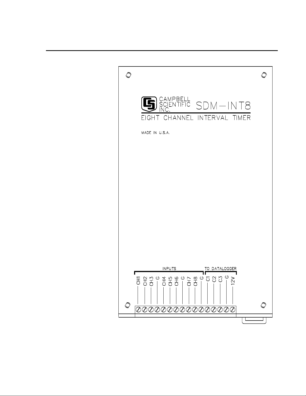
FIGURE 1. SDM-INT8 Front Panel
1
Page 8
SDM-INT8 8 Channel Interval Timer
1. Overview
The 8 channel Interval Timer (INT8; see Figure 1) is a measurement module
which outputs processed timing information to a 21X, CR10(X), CR23X,
CR800, CR850, CR1000, CR3000, CR5000, or CR9000(X) datalogger. Each
input channel is programmed to detect transitions from low or high level
voltage inputs (Figure 2). Period, pulse width, frequency, counts, and time
intervals are output to the datalogger for further processing/logging.
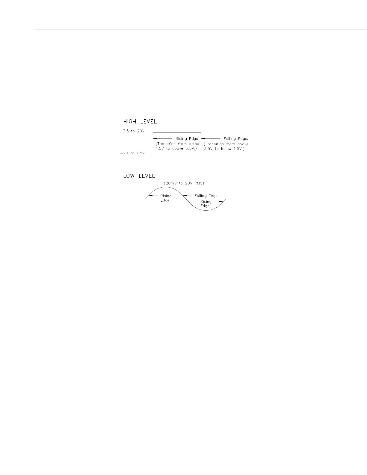
FIGURE 2. Voltage Input Options, Edges, and Thresholds
In CRBasic, the SDMINT8 instruction is used to program and control the
SDM-INT8; in Edlog, Instruction 101 is used. These instructions, address,
command, and receive data from the INT8 through three ports on the
datalogger (see Section 3). Multiple INT8s, each with a unique address, may
be controlled by one datalogger.
The INT8 has its own processor which enables it to make measurements and
process data while the datalogger is performing other tasks. Each of the 8
channels may be independently programmed to detect either rising or falling
edges and perform the following functions (Section 5.1.3).
The INT8 can capture timing events with 1 microsecond resolution over a
maximum range of 16.77 seconds. Timing on different channels can be
compared to within ± 1 microsecond. At the same time, the datalogger can be
executing various analog measurements, but the exact time these
measurements are taken is subject to the datalogger's timing resolution.
Section 7.3 discusses the possibilities and limitations of synchronizing INT8
and datalogger measurements.
2
Page 9

2. Specifications
Operating voltage: 9.6 V to 16 V DC
Current drain: 13 to 20 mA active, 400 microamp quiescent
Environmental: -25 to +50 degrees Celsius 0 to 90% RH (non-condensing)
Number of channels: 8
Maximum timing measurement: 16.7 seconds
Resolution: ± 1 microsecond
Dimensions: 8 x 5 x 1 in (13 x 20 x 2 cm)
Weight: 1.4 lbs (635 g)
Input voltage option per channel: high level, low level
SDM-INT8 8 Channel Interval Timer
High Level Voltage Input
- Minimum pulse width: 2 microseconds
- Signals edges:
rising: transition from < 1.5 to > 3.5 volts
falling: transition from >3.5 to<1.5 volts
Maximum input voltage: 20 volts
- Maximum frequency:
5.1 kHz when using Averaging Options
10 kHz when Capturing All Events
The Low Resolution Frequency function allows higher frequencies to be
measured if it is used on all programmed channels with Execution Interval
Averaging. Maximum frequency is dependent on the number of channels
programmed, as shown below:
No. of Channels
1 42.5
2 17.5
3 11.0
4 8.6
5 5.2
6 4.8
7 4.5
8 4.28
Max Freq (kHz)
:
Low Level Voltage Input:
- Minimum AC voltage: 20 millivolts RMS
- Input Hysteresis: 11 millivolts
- Maximum AC voltage: 20 volts RMS
- Minimum frequency: 1 Hz
- Maximum frequency:
3
Page 10

SDM-INT8 8 Channel Interval Timer
Minimum AC Max Freq.
voltage RMS
20 mV 100
50 mV 400
150 mV 1000
2.5 V - 20 V 4000
3. Connections
The CABLE5CBL-L cable connects the SDM-INT8 to a datalogger. The
datalogger-to-SDM-INT8 connections are shown in Figure 3. Please note that
the SDM-INT8 connects to the CR9032 CPU module of the CR9000X and the
CR9080 PAM module of the CR9000. INT8s are shipped from the factory
with a 10K Ohm resistor attached to the terminal strip for the convenience of
21X user. This resistor is necessary only when the INT8 is used with a 21X
datalogger.
(Hz)
CAUTION
CAUTION
Except for the 21X, the order in which the datalogger and
SDM-INT8 connections are made is critical. The
datalogger cases and wiring panel bracket are at
datalogger ground. To avoid accidentally shorting 12 V to
the case, connect the 12 V first then the ground. To
prevent voltages in excess of 5 V from entering the
datalogger’s SDM ports (C1 to C3 or SDM-C1 to SDM-C3),
the ports are wired after connecting the ground lead.
For the 21X, a 10K resistor is wired between Control Port 1 and single ended
input 1 (1H). The order in which 21X/INT8 connections are made is not
critical.
The CABLE5CBL-L has a user-specified length. A 1-ft length should be
sufficient when both datalogger and SDM-INT8 are housed in an ENC12/14
enclosure; a 2-ft length may be required if the datalogger and SDM-INT8 are
housed at opposite ends of an ENC16/18. The total cable length for all SDMs
should be as short as possible and preferably does not exceed 20 feet. Longer
lead lengths may be possible for CRBasic dataloggers if the SDMSpeed
instruction is used (see Section 5.1.2). Long lead lengths may prevent
communication.
The signal input lines of the INT8 are protected against the
continuous connection of voltages up to 20 VDC and
against high voltage electrostatic discharge. However,
where there are long cable runs (>3 m) to the sensor and
particularly when the cables run outside, some extra
protection may be required for these inputs to protect the
inputs against high energy surges, as may be induced by
lightning. Please contact Campbell Scientific for further
advice.
4
Page 11
CR800,
CR850,
CR9032
(CR9000X),
CR9080
(CR9000),
CR10(X),
CR23X,
or
CR1000
CR3000,
CR5000
12V
SDM-C3
SDM-C2
SDM-C1
SDM-INT8 8 Channel Interval Timer
G
10K OHM
RESISTOR
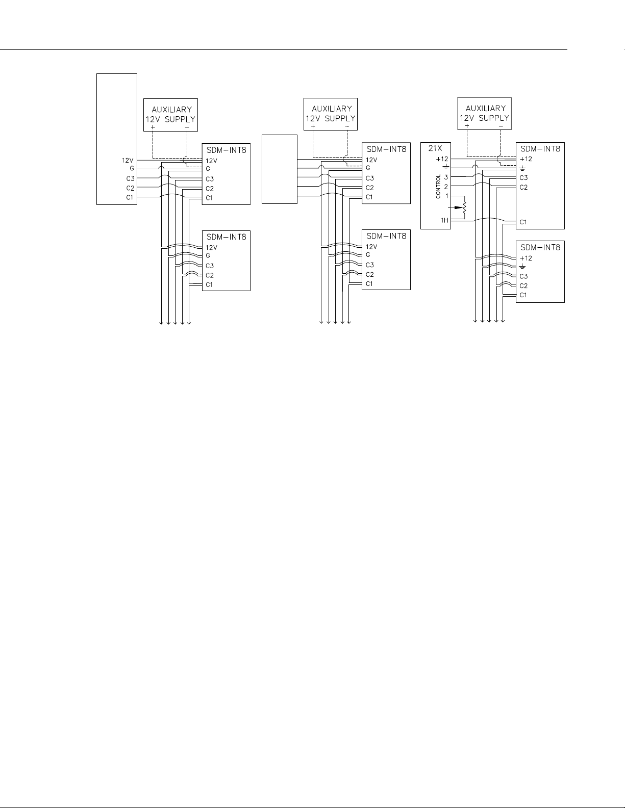
FIGURE 3. Wiring Diagram
4. Power Supply Considerations
The datalogger's power supply is typically used to power the INT8, however,
an auxiliary supply may be used as shown in Figure 3. When selecting a
power supply, consideration must be given to the active current drain and the
active time of the INT8. With two exceptions, if the INT8 is programmed it is
drawing 13 to 20 mA. The two exceptions are:
• When the Specified Averaging Interval (Output Option Section 5.4) is
selected, the INT8 enters the quiescent current drain state (400 microamp
current drain) after returning the results to the datalogger.
• If the interval between executions of Instruction 101 exceeds 16.77
seconds, the INT8 enters the quiescent current drain state.
If a 21X datalogger is used to power the INT8, all low level analog
measurements (thermocouples, pyranometers, etc.) must be made
differentially. This is due to slight shifts in the ground potential on the
terminal strip when the 21X is used to power external devices.
5. Programming the Datalogger
The datalogger is programmed using either CRBasic or Edlog. Dataloggers
that use CRBasic include our CR800, CR850, CR1000, CR3000, CR5000, and
CR9000(X). Dataloggers that use Edlog include CR7, CR10(X), CR23X, and
21X. Both CRBasic and Edlog are provided in LoggerNet and PC400.
5
Page 12

SDM-INT8 8 Channel Interval Timer
5.1 CRBasic Programming
5.1.1 Instruction SDMINT8
The SDMINT8 instruction is used to program and control the SDMINT8
interval timer module. Description of the instruction follows.
Syntax
SDMINT8 (Dest, SDMAddress, Config8_5, Config4_1, Funct8_5, Funct4_1,
OutputOpt, CaptureTrig, Mult, Offset)
Dest: Dest is used to specify the array where the results of the instruction are
stored. For all output options except Capture All Events (-nnnn), the Dest
argument should be a one dimensional array with as many elements as there
are programmed INT8 channels. If the Capture All Events output option is
selected, the Dest array must be two dimensional. The magnitude of first
dimension should be set to the number of functions (up to 8), and the
magnitude of the second dimension should be set to at least the maximum
number of events to be captured. The values will be loaded into the array in the
sequence of all of the time ordered events captured from the lowest
programmed channel to the time ordered events of the highest programmed
channel.
NOTE
SDMAddress: This parameter is used to define the address of the INT8 with
which to communicate. Valid SDM addresses are 0 through 14 (factory default
is 0). Address 15 is reserved for the SDMTrigger instruction. If the Reps
parameter is greater than 1, the datalogger will increment the SDM address for
each subsequent device that it communicates with. See Section 6.1 for further
detail.
CRBasic dataloggers use base 10 when addressing SDM devices.
Edlog programmed dataloggers (e.g., CR10X, CR23X) used
base 4 for addressing.
Config8_5: The Config8_5 parameter is a four-digit code used to configure
channels 5 through 8 on the INT8. Each input channel can be configured for
either high or low level voltage inputs and for rising or falling edges. The
digits represent the channels in descending order from left to right (e.g., 8 7 6
5). As an example, the code 0303 would program channels 8 and 6 to capture
the rising edge of a high level voltage, and channels 5 and 7 to capture the
falling edge of a low level voltage. See Section 2 for information about the
specification requirements of high and low level voltage signals.
Description
Code
0 High level, rising edge
1 High level, falling edge
2 Low level, rising edge
3 Low level falling edge
6
Config4_1: The Config4_1 parameter is a four-digit code used to configure
channels 1 through 4 on the INT8. It is identical in function to Config8_5. The
digits represent the channels in descending order from left to right (e.g., 4 3 2
1).
Page 13

SDM-INT8 8 Channel Interval Timer
Function8_5: The Function8_5 parameter is a four digit code used to program
the timing function of channels 5 through 8. Similar to the Config parameters,
digits represent the channels in descending order from left to right (e.g., 8 7 6
5). See Section 6.3 for further details about these functions.
Description
Code
0 No value returned
1 Period (ms) between edges on the programmed channel
2 Frequency (kHz) of edges on the programmed channel
3 Time (ms) between an edge of the previous channel and an edge of
the programmed channel
4 Time (ms) between an edge on Channel 1 and edge on the
programmed channel
5 Number of edges on channel 2 since last edge on channel 1 using
linear interpolation
6 Low resolution frequency (kHz) of edges on programmed channel
7 Total count of edges on programmed channel since last interrogation
8 Number of edges on channel 2 since last edge on channel 1 without
linear interpolation
Function4_1: The Function4_1 parameter is a four digit code used to program
the timing function of channels 1 through 4. It is identical in function to
Function8_5. The digits represent the channels in descending order from left to
right (e.g., 4 3 2 1).
OutputOpt: The OutputOption parameter is a numeric code that is used to
select one of the five different output options. The selected option will be
applied to all of the INT8 channels. A brief explanation is given below for
each code. See Section 6.4 for detailed explanations of each option.
0: Stores an average of the event data since the last time that the INT8 was
interrogated by the datalogger. If no edges were detected, 0 will be returned for
frequency and count functions, and 99999 will be returned for the other
functions. The INT8 ceases to capture events during communications with the
datalogger, thus some edges may be lost.
32768: Performs continuous averaging, which is utilized when input
frequencies have a slower period than the execution interval of the datalogger.
If an edge was not detected for a channel since the last time that the INT8 was
polled, then the datalogger will not update the Dest for that channel. The INT8
will capture events even during communications with the datalogger.
nnnn: Averages the input values over "nnnn" milliseconds. The datalogger
program is delayed by this instruction while the INT8 captures and processes
the edges for the specified time duration and sends the results back to the
datalogger. If no edges were detected, 0 will be returned for frequency and
count functions, and 99999 will be returned for the other functions.
-nnnn: Instructs the INT8 to capture all events until "nnnn" edges have
occurred on channel 1, until the datalogger addresses the INT8 with the
CaptureTrig argument true, or until 8000 events have been captured. When the
CaptureTrig argument is true, the INT8 will return up to the last nnnn events
for each of the programmed INT8 channels, reset its memory, and begin
capturing the next nnnn events. The INT8 waits for the first edge on channel 1
7
Page 14

SDM-INT8 8 Channel Interval Timer
as a trigger to start making measurements. The Dest parameter must be
dimensioned large enough to receive the captured events.
-9999: Initiates a self memory test of the INT8. A numeric code is returned to
indicate the results of the test.
Code
0 Bad ROM
-0 Bad ROM and bad RAM
positive integer: Good ROM (value returned is the ROM signature) and good
RAM
negative integer: Good ROM (value returned is the ROM signature) and bad
RAM
CaptureTrig: This argument is used when the Capture All Events output
option is used. When CaptureTrig is true, the INT8 will return the last nnnn
events.
Mult: The multiplier with which to scale the raw data.
Description
Offset: The offset that is to be applied to the raw data.
NOTE
This instruction must NOT be placed inside a conditional
statement when running in pipeline mode.
5.1.2 SDMSpeed Instruction
The SDMSpeed instruction is used to change the bit period that the datalogger
uses to clock the SDM data. Slowing down the clock rate may be necessary
when long cable lengths are used to connect the datalogger and SDM devices.
The syntax of this instruction is as follows:
SDMSpeed (BitPeriod
The BitPeriod argument can be an integer or a variable. If the SDMSpeed
instruction is not in the program, a default bit period is used. If 0 is used for
the argument, the minimum allowable bit period is used. Table 1 shows the
default, minimum allowable, and maximum bit period for each of our CRBasic
dataloggers.
Datalogger
)
TABLE 1. Bit Period Values
Default
Bit Period
Minimum Allowable
Bit Period
Maximum
Bit Period
8
CR800, CR850
CR1000
CR3000
CR5000
26.04 μsec 8.68 μsec
26.04 μsec 8.68 μsec
26.04 μsec 8.68 μsec
30 μsec 8 μsec
2.2 msec
2.2 msec
2.2 msec
3 msec
Page 15

SDM-INT8 8 Channel Interval Timer
The equation used to calculate the bit rate depends on the datalogger used.
The datalogger will round down to the next faster bit rate.
Equation for CR800, CR850, and CR1000:
bit_rate=INT((k*72)/625)*Resolution
Where:
k= the value entered in BitPeriod
Resolution=8.68 microseconds
Equation for CR3000:
bit_rate=INT((k*144)/625)*Resolution
Where:
k= the value entered in BitPeriod
Resolution= 4.34 μsec.
Equation for CR5000:
bit_rate=INT(k*20)*Resolution
Where:
k= the value entered in BitPeriod
Resolution=50 nsec.
5.2 Edlog Programming (Instruction “101”)
In Edlog, Instruction 101 (see Table 2) is used to address, command, and
retrieve data from the INT8. On the first execution of Instruction 101, the
INT8 is programmed. Subsequent executions of Instruction 101 may
command the INT8 to send its processed data to the datalogger or to
reinitialize its measurement process. If multiple INT8s are connected to a
datalogger, each INT8 must have a corresponding Instruction 101 and a unique
address.
The datalogger tracks the first time a 101 Instruction is executed to know if the
associated INT8 is programmed or not. If two or more 101 Instructions are
used to address the same INT8, the first execution of each Instruction will
program the INT8 returning no data. If the INT8 must be called more than
once per datalogger execution interval, place Instruction 101 in a subroutine
and call the subroutine when Instruction 101 must be executed. The INT8 is
programmed on the first call, with data being returned on subsequent calls.
9
Page 16

SDM-INT8 8 Channel Interval Timer
Parameter Data Description
Type
01: 2 Address (Section 6.1)
02: 4 *Input config; channels 8,7,6,5
03: 4 *Input config; channels 4,3,2,1
04: 4 **Function; channels 8,7,6,5
05: 4 **Function; channels 4,3,2,1
06: 4 ***Output option
07: 4 Loc
08: FP Mult
09: FP Offset
Execution time: 2.3 ms + 1.65 ms/value + averaging interval
(See Appendix B to estimate processing time on higher
Intermediate Storage: 1 location
* Input configurations (Section 6.2):
0 = high level, rising edge
1 = high level, falling edge
2 = low level, rising edge
3 = low level, falling edge
**Functions (Sec. 6.3):
0 = no value returned
1 = period in ms
2 = frequency in kHz
3 = time since previous channel is ms
4 = time since channel 1 in ms
5 = counts on channel 2 since channel 1
6 = low resolution frequency in kHz
7 = counts
8 = integral counts on channel 2 since channel 1
*** Output (Sec. 6.4):
0 Execution interval averaging
0- - Continuous averaging
XXXX Specified averaging interval in ms, XXXX>0
XXXX- - Capture all events until XXXX edges of channel 1
9999- - Test memory
TABLE 2. Instruction 101
frequency signals)
(0<XXXX<8000)
6. Programming Details
6.1 SDM Address
The INT8 is enabled by an address sent from the datalogger. A terminal block
located inside the INT8 has two jumpers which define the INT8 address. The
address defined by the jumpers must match the address entered into SDMINT8
or Instruction 101. The jumpers are set at the factory for address 00. If the
jumpers have not been changed, the SDM address entry is 00. Each INT8
10
Page 17

connected to the datalogger must have a unique address. See Appendix A for
details on changing the address.
6.2 Input Configuration
Each of the 8 input channels can be configured for either high level or low
level voltage input, and for rising or a falling edge detect (see Figure 2). One
digit (0,1,2, or 3) is specified to configure each channel, as shown below.
0 = high level, rising edge
1 = high level, falling edge
2 = low level, rising
3 = low level, falling
Example:
Channel 1 thru 5: high level, rising edge
Channel 6: high level, falling edge
Channel 7 and 8: low level, rising
02:2210 (channels 8,7,6,5)
03:0000 (channels 4,3,2,1)
SDM-INT8 8 Channel Interval Timer
6.3 Functions
Each of the 8 channels can be programmed independently for various timing
functions. Channel functions are programmed with one digit (0,1,2,3,4,5,6,7,
or 8) for each channel. Functions 0 through 8 are described below.
0 - no value
1 - Period (ms)--
The time between signal edges on this channel in milliseconds.
2 - Frequency (kHz)--
The frequency of signal edges on this channel in kHz. Frequency is
calculated from a measurement of period.
3 - Time since previous channel (ms)--
The time between the signal edge on the next lower numbered channel
and the signal edge on this channel is in milliseconds. This function can
be used to measure pulse width by connecting the signal to two adjacent
channels programmed with opposite edge detect directions.
4 - Time since channel 1 (ms)--
The time between the signal edge on channel 1 and signal edge on this
channel is in milliseconds.
5 - Count on channel 2 since channel 1--
The number of signal edges on channel 2 between channel 1's signal edge
and this channel's signal edge. Linear interpolation is used to derive a
fraction of a count at both the beginning and end of counting
11
Page 18

SDM-INT8 8 Channel Interval Timer
6 - Low resolution frequency (kHz)--
Higher frequencies may be measured if fewer channels are used (see
For this function, any data value less than 1 is returned as 0. This must be
The frequency is returned to the datalogger in a low resolution format (16
Fewer bits are transferred to the datalogger in the 16 bit format, speeding
7 - Counts--
For this function to return low resolution data, it must be the only function
used in the instruction. If this is not the only function used in the
instruction, it returns high resolution data, the same as Function 2.
Section 2, Specifications).
considered when calculating the multiplier and offset (Parameters 8 and
9).
bit floating point). This format allows for a range of positive real
numbers between 1 and 65480 with 4 digit resolution on values whose
mantissa is less than 8192. Three (3) digit resolution is given on values
with mantissas greater than or equal to 8192.
up the instruction execution time by 0.3 ms per value.
"Counts" will always return an integer value when Instruction 101 is
executed. The value will be the number of edges that have occurred since
the last execution of Instruction 101. If no edges have occurred, a zero is
returned. This function does not work with the Capture All Events
Output Option.
If counts are being totalized by the datalogger, use the Continuous
Averaging Output with "Counts" to avoid missing any counts (Section
5.4).
8 - Integral counts on chnl 2 since chnl 1--
Same as function 5 with no linear interpolation.
Example: The INT8 is used in an automotive test to measure crank
angle, engine RPM when spark #1 fires, and fuel injector duty cycle.
Parameters 2 and 3 are programmed as follows:
Parameter 2:0001 (channels 8,7,6,5)
Parameter 3:0000 (channels 4,3,2,1)
Channel 1: crank shaft reference pulse, rising edge (0)
Channel 2 pulse from the flywheel teeth, rising edge (0)
Channel 3: pulse from spark #1, rising edge (0)
Channel 4: fuel injector pulse, rising edge (0)
Channel 5: fuel injector pulse, falling edge (1)
Parameters 4 and 5 are programmed for the following functions:
Parameter 4:0003 (channels 8,7,6,5)
Parameter 5:2502 (channels 4,3,2,1)
12
Page 19

Channel 1: frequency (2)
Channel 3: counts on channel 2 since channel 1 (5)
Channel 4: frequency (2)
Channel 5: time since previous Channel (3)
Channel 2,6,7,8: none (0)
Channel 1: RPM may be calculated from crankshaft frequency.
Channel 3: Flywheel teeth count between the crankshaft reference
Channel 4: The frequency of fuel injection may be multiplied by
Channel 5: Time of the positive pulse width of the fuel injector is given
6.4 Output Option
An important conceptual difference between Output Options and Functions is
that one Output Option is selected per Instruction (SDMINT8 or Instruction
101) and applied to data from all channels. Functions are applied to individual
channels.
SDM-INT8 8 Channel Interval Timer
pulse, and the spark gives reference to the crank angle.
channel 5's positive pulse width to yield fuel injector duty
cycle. The multiplication is not performed in the INT8.
in milliseconds.
6.4.1 Rules for Averaging
This Section applies to only those Output Options which perform averaging
(i.e., 0, 32768, nnnn in SDMINT8 or 0, 0--, XXXX in Instruction 101).
Averaging is performed on events which are defined by at least two edges. For
example, to average a period two rising edges are required to define a period.
To average the time since the previous channel, an edge on the previous
channel followed by an edge of the channel programmed for time since
previous channel is required.
No averaging is done on channels programmed for Function 7, "Counts".
Channels programmed for counts do not require two edges for an event.
Single edges of the specified direction are counted.
The maximum interval that the INT8 can time is 16.77 seconds. Edges which
are separated by a time longer than this will result in a false measurement.
In all Output Options that average, the INT8 is storing measurements and
processing. The measuring/storing task takes priority over the processing task.
If the input signal exceeds a certain frequency, processing will lag behind
measuring/storing. Table 3 provides the maximum average frequency at which
the processing task keeps up with the measuring/storing task.
13
Page 20

SDM-INT8 8 Channel Interval Timer
TABLE 3. Input Frequency (kHz) at Which Processing
N 1,2,6,7 3 4 5 8
1 * 3.4 3.7 0.14 - 0.05F2 3.4 - 0.81F2
2 3.5 1.6 1.7 0.07 - 0.02F2 1.6 - 0.38F2
3 2.1 0.99 1.1 0.05 - 0.02F2 0.99 - 0.24F2
4 1.4 0.70 0.76 0.04 - 0.01F2 0.70 - 0.17F2
5 .99 0.53 0.57 0.03 - 0.01F2 0.53 - 0.13F2
6 .75 0.42 0.45 0.02 - 0.01F2 0.42 - 0.10F2
7 .59 0.34 0.37
8 .47 0.28 0.30
N = Number of channels measuring given Function
* = Greater than the maximum input frequency of 5.1 kHz
F2 = Average input frequency on channel 2
See Appendix B to formulate the equations used to generate
Table 3. Frequencies show in Table 3 are for "worst case"
conditions. Faster input frequencies are possible depending on
the phase relationship of the channel to channel signal.
With Options 0, 32768, and 0--, the average returned to the datalogger is the
most recently processed average when the INT8 is addressed. If processing
lags measuring/storing, the number of samples used in the average is reduced
as is the effective averaging interval. For functions that average, this is not a
problem, assuming the input frequency does not change significantly over the
sampling interval. It is a problem if counts are being totalized (Function 7,
Output Option 32768 or 0--). In this case the count will intermittently be low
(Section 6.4.3).
Time Equals Measuring/Storing Time
14
The Specified Averaging Interval Option (nnnn or XXXX) uses all events
captured over the specified interval to calculate an average. If the processing
tasks gets behind the measuring/storing task, the additional time required to
process all the edges is taken at the expense of the execution time (refer to
Table 3.)
Due to finite memory in the INT8, when processing lags behind by 800 edges,
the measuring/storing task is suspended for that interval. For Option nnnn or
XXXX to average over the entire specified interval, the interval must be short
enough to prevent the processing tasks from getting behind by more than 8000
edges. Table 4 gives the sampling interval at which 8000 unprocessed events
will accumulate for a given input frequency.
Page 21

SDM-INT8 8 Channel Interval Timer
TABLE 4. Sampling Interval (Seconds) to Accumulate
8000 Unprocessed Events for Functions 1,2,6,7
Input Number of Channels
Freq. kHz 3 4 5 6 7 8
1.1 5.26
1.3 7.97 2.84 1.48
1.5 4.21 1.81 1.00
1.7 2.67 1.26 .73
1.9 5.62 1.87. .93 .55
2.1 3.68 1.38 .72 .43
2.3 2.64 1.07 .57 .35
2.5 2.00 .86 .47 .29
2.7 6.55 1.57 .7 .39 .24
2.9 4.64 1.27 .58 .33 .20
3.1 3.50 1.05 .49 .28 .18
3.3 2.76 .88 .42 .24 .15
3.5 2.24 .75 .37 .21 .13
3.7 1.86 .65 .32 .19 .12
3.9 1.57 .57 .28 .17 .11
4.1 1.35 .50 .25 .15 .10
4.3 8.91 1.17 .45 .23 .13 .09
4.5 6.73 1.03 .40 .20 .12 .08
4.7 5.33 .91 .36 .19 .11 .07
4.9 4.36 .81 .33 .17 .1 .06
5.1 3.65 .73 .30 .15 .09 .06
Sampling intervals shown in Table 4 are for "worst case"
conditions. Longer sampling intervals are possible
depending on channel phase relationships. See Appendix B
to calculate maximum intervals for other Functions.
When the low resolution frequency function is used, summing is not required;
an average over the full interval is always available.
In all options that do averaging, the functions that involve time or count
differences between different channels (time since channel 1, counts on 2 since
1, and time since previous channel) behave as follows: if there are multiple
beginning edges and/or ending edges, i.e., more than 1 beginning edge per
ending edge or visa versa, then only the last of the beginning edges and the
first of the ending edges are used in the average. For example, assume all
detection is on rising edges, and the function is counts on channel 2 since 1 for
channel 3. A diagram of this example is presented in Figure 4. Multiple
beginning edges are shown on channel 1, and multiple ending edges on
channel 3. In this example, only 2 edges are used in the average.
15
Page 22

SDM-INT8 8 Channel Interval Timer
FIGURE 4. Example of Multiple Beginnings and Endings
6.4.2 Option 0: Execution Interval Averaging
When Option 0 is selected, the result from each channel is a value averaged
over the interval since the INT8 was previously addressed. Normally this
would be the execution interval. The value returned to the datalogger is the
average at hand when the INT8 is addressed. If processing lags the
measuring/storing task, the unprocessed events are not used in the averaging
and are deleted from memory.
With Option 0, the datalogger should be programmed to execute Instruction
101 at least every 16.77 seconds while making measurements. If this period is
exceeded, the INT8 enters a low power stand by mode and events are missed.
If no event occurs during the interval, 0 is returned for frequency and count
functions, and 99999 (infinity) is returned for the other functions.
With Option 0, the INT8 ceases to capture events while it is communicating
with the datalogger and reinitializes its measurement operation afterwards.
Thus, edges that occur during this communication period (generally 2.3 ms +
1.7 ms/value) are ignored by the INT8.
6.4.3 Option 32768 or 0--: Continuous Averaging
The Continuous Averaging Option is similar to Option 0 with the following
differences:
1. The INT8 keeps capturing input edges during communication with the
datalogger. If the time required for processing is less than or equal to the
time required for measuring/storing (see Table 3), events will not be
missed.
2. The datalogger will not update the input location of a channel that has not
had an event since the last time the INT8 was addressed.
With the Continuous Averaging option, the datalogger should be programmed
to execute SDMINT8 instruction or Instruction 101 at least every 16.77
seconds while making measurements. If this period is exceeded, the INT8
enters a low power stand by mode and events are missed.
16
The Continuous Averaging option is designed for input frequencies or
intermittent signals that are at a slower rate than the execution interval of the
datalogger. It is also used for totalizing counts.
Page 23

SDM-INT8 8 Channel Interval Timer
Assume the input frequency is 0.5 Hz, and the execution interval of Instruction
101 is 10 Hz. The datalogger input location is updated at about 0.5 Hz if a
change occurred, not every time the INT8 is addressed.
An example of an intermittent signal is a Cub Scout Pinewood Derby where
the measured event is the elapsed time of a race, but several minutes separate
each heat. Three cars per heat are gravity powered down a straight track. The
start of the race triggers an edge on INT8 channel 1. The three cars each
trigger an edge on separate channels as they cross the finish line. Function 4 is
used to measure "time since channel 1" to provide the elapsed time for each
car. The datalogger can be addressing the INT8 as often as desired with this
option, but variables or input locations will only be updated at the finish of a
new heat.
The Continuous Averaging Option is used for totalizing counts (Function 7)
because the INT8 continues to measure and store events even when
communicating with the datalogger. However, counts will be missed if the
measuring/storing task exceeds the processing task (see Table 3).
6.4.4 Option nnnn or XXXX: Specified Averaging Interval
Option nnnn or XXXX is used to average over an exact interval when the
instruction is executed. The averaging interval is specified in units of
milliseconds. The datalogger program is delayed for the specified interval
while the INT8 captures, edges, plus the extra time required for processing if
the processing task lags behind the measuring/storing task. After returning the
results to the datalogger, the INT8 enters the low power standby mode (400
microamp current drain), increasing battery life.
Like Option 0, this option will return 0 for frequency and count functions and
99999 for all functions if no result is available during the specified interval, i.e.
the signal was too slow.
6.4.5 Option –nnnn or XXXX--: Capture All Events Until nnnn or XXXX Edges On Channel 1
6.4.5.1 Option –nnnn
Option –nnnn instructs the INT8 to capture all events until “nnnn” edges have
occurred on channel 1, until the datalogger addresses the INT8 with the
Capture Trigger argument true, or until 8000 events have been captured.
When the CaptureTrig argument is true, the INT8 will return up to the last
nnnn events for each of the programmed channels, reset its memory, and begin
capturing the next nnnn events. The INT8 waits for the first edge on channel 1
as a trigger to start making measurements. The Dest parameter must be
dimensioned large enough to receive the captured events.
6.4.5.2 Option XXXX--
Option XXXX-- outputs all available timing information with no averaging.
"All events" means that every occurrence of each programmed functions is
recorded, i.e., each period, each pulse width, etc. as opposed to one averaged
value.
17
Page 24

SDM-INT8 8 Channel Interval Timer
Since the number of values returned may be variable, making it difficult to
assign a fixed number of input locations, the Capture All Events Option
outputs data directly to the datalogger's Final Storage when Instruction 101 is
executed.
If the Output Flag is not set when the instruction is executed, the datalogger
commands the INT8 to start measuring, and no results are returned. If the
Output Flag is set, the datalogger retrieves the events that have been stored
since the last time the instruction was executed and stores them directly in
Final Storage. Data from the lowest numbered programmed channel are output
first. Each subsequent channel's output has a new array ID which is
incremented by 1. When all data are transferred, the INT8 starts its measuring
process again.
The INT8 waits for the first edge on channel 1 as a "trigger" to start making
measurements. It will then capture edges until XXXX edges on channel 1, or
until the datalogger again addresses it, or until 8000 edges have been captured,
whichever happens first. Output will not be returned until Instruction 101 is
executed with the Output Flag set, even if the edge limits are reached.
With this option, Instruction 101 does not have to be executed every 16.77
seconds. The INT8 will continue to measure without entering the low power
mode until 8000 edges are captured. Events being measured by the INT8 must
not exceed 16.77 seconds, or false measurements will be returned. The
maximum input is 10 kHz for all channels.
On a 10 second one-shot test, for example, Instruction 101 could be executed
with the Output Flag cleared and then executed 10 seconds later with the
Output Flag set. Or, Instruction 101 could be placed in a subroutine and called
from different points in the programs.
For a 10 second test repeated every 10 seconds, the Output Flag could be set
every time the instruction is executed.
Analog measurements can be made by the datalogger while the INT8 is
capturing events. To some degree, and with caution, datalogger measurements
can be synchronized with INT8 measurements. For example, the datalogger
can execute the Burst Mode after executing Instruction 101 and trigger on the
same signal that triggers channel 1 of the INT8. The caution is that the trigger
on channel 1 cannot occur before the datalogger has a chance to enter the Burst
Mode. To synchronize datalogger and INT8, the Burst Mode should be ready
and waiting for the "trigger".
6.4.6 Option 9999--: Test Memory
Option 9999-- causes the INT8 to do a self memory test instead of measure
and process timing functions. The signature of the INT8 PROM is returned to
the datalogger's Input Location of the initial execution of the instruction. If the
value is negative it indicates bad RAM; 0 indicates a bad PROM, as shown in
Table 5.
18
Page 25

SDM-INT8 8 Channel Interval Timer
TABLE 5. Definition of Test Memory
Option Output
Output Definition
positive integer = ROM signature, good RAM
negative integer = ROM signature, bad RAM
0 = bad ROM
-0 = bad ROM, bad RAM
A result of executing Option 9999-- is that the program residing in the INT8 is
deleted, and the INT8 goes into the low current drain standby mode. To initiate
INT8 measurements, SDMINT8 or Instruction 101 must be executed without
9999--.
6.5 Dest, Input Location, Multiplier, and Offset
For the SDMINT8 instruction, Dest is used to specify the array where the
results of the instruction are stored. For all output options except Capture All
Events (-nnnn), Dest argument should be a one dimensional array with as
many elements as there are programmed INT8 channels. If the Capture All
Events output option is selected, the Dest array must be two dimensional. The
magnitude of the first dimension should be set to the number of functions (up
to 8), and the magnitude of the second dimension should be set to at least the
maximum number of events to be captured. The values will be loaded into the
array in the sequence of all of the time ordered events captured from the lowest
programmed channel to the time ordered events of the highest programmed
channel.
For Instruction 101 the input location is designated in parameter 7. Except for
the Capture All Events Options, data from the INT8 are returned to the starting
input location in ascending programmed channel order. Output from Capture
All Events is returned directly to Final Storage in the datalogger.
Except for the "Test memory" option, the multiplier and offset are applied to
all results by the INT8 before they are returned to the datalogger.
For Low Resolution Frequency (Function 6), any value less then 1 is returned
as 0. This must be considered when calculating the multiplier and offset.
6.6 Edlog Output Format
The Output Option specifies the format of the output received by the
datalogger. The format of the three options that do averaging (Options 0, 0--,
and XXXX) are identical. A single value for each programmed channel is
stored in consecutive input locations starting at the location specified in
parameter 7, Instruction 101. If only three INT8 channels are programmed,
then only three Input Locations will be utilized. Output Processing
Instructions, such as Instruction 70 (Sample) must be used to store the results
in Final Storage.
19
Page 26

SDM-INT8 8 Channel Interval Timer
When using the Capture All Events Option (no averaging), the data are
directed to Final Storage of the datalogger rather than Input locations. The
first execution of Instruction 101 will program the INT8. Subsequent
executions of Instruction 101 with the Output Flag set will output all events to
Final Storage. If the Output Flag is not set, the INT8 will be reinitialized with
out returning any data. The output returned for each programmed channel will
be all events that have occurred since the last execution of Instruction 101.
Each channel will have a unique Array ID. If other Output Processing
Instructions precede Instruction 101, the first channel's data will be grouped
with the previous Final Storage data (i.e. same Array ID.). This first Array ID
will be incremented by one for each additional programmed channel.
Output for the Test Memory Option is a single value returned to the specified
input location.
7. Program Examples
These examples are given to demonstrate concepts. The starting conditions for
each example are followed by a datalogger program. These examples are not
to be used verbatim.
7.1 CRBasic Program Example
Measure 2 Wind Sentry Anemometer (03101) on CR1000 pulse channel P1
and P2 and measure 5 Wind Sentry Anemometer (03101) connected to the
SDM INT8 channel 1 through channel 5. See Section 5.1.1 for a description of
the CR1000 “SDMINT8” instruction parameters.
Wiring
CR1000 SDMINT8
12 V 12 V
Gnd Gnd
C1 C1
C2 C2
C3 C3
Sensor Wiring
SDM-INT8
CH1 Black - WS #1
CH2 Black - WS #2
CH3 Black - WS #3
CH4 Black - WS #4
CH5 Black - WS #5
All white and clear wires are
connected to ground.
Note: Set/check the SDM
Address on this module.
20
Page 27

SDM-INT8 8 Channel Interval Timer
‘Declare Public Variables
Public Int8(5)
Public PulseCh(2)
Dim I
‘Define Data Tables
DataTable (Dat5min,1,-1)
DataInterval (0,5,Min,10)
average (5,Int8(),FP2,False)
EndTable
‘Main Program
BeginProg
Scan (5,Sec,0,0)
‘measure 03101 on P1 & P2 WS_ms:
PulseCount (PulseCh(1),1,1,1,1.75,.2)
PulseCount (PulseCh(2),1,2,1,1.75,.2)
‘measure 03101 on SDMINT8 channel 1 through channel 5
SDMINT8 (Int8(),3,0002,2222,0002,2222,0,1,1.75,.2)
‘For I = 1 to 5
‘If Int8(I)<0.21 Then Int8(I)=0
‘next I
‘Call Data Tables and Store Data
CallTable Dat5min
NextScan
EndProg
7.2 Edlog Program Examples
7.2.1 Cold Crank Engine Test - Capture All Events
The INT8 is used to obtain timing information during 20 crank cycles or 10
seconds of a 4 cylinder engine cold start test. A crank shaft reference pulse is
wired into channel 1. Pulses from the flywheel enter channel 2 so that the
counts on 2 since 1 function can be used to measure crank angle. The 4 spark
plug firings are picked off a distributor wire and fed into channel 3. Channels
4 and 5 hook onto a fuel injector pulse for measurement of fuel injection pulse
width.
The inputs into channels 1 - 5 are as follows:
Channel 1 - crank shaft reference pulse, rising edge
Channel 2 - pulse per flywheel tooth, rising edge
Channel 3 - pulses from the four spark plugs, rising edge
Signals common to single distributor pick-up wire
Channel 4 - fuel injector "on" pulse, rising edge
Channel 5 - fuel injector "on" pulse, falling edge
The channel functions are programmed as follows:
Channel 1 - Frequency, to get RPM
Channel 3 - Counts on 2 since 1, to get crank angle of the spark plug firings
Channel 5 - Time since previous channel to get pulse widths of the fuel
injector.
21
Page 28

SDM-INT8 8 Channel Interval Timer
Parameter 6 (Capture All Events) is programmed for 20--to capture edge times
on channels 1-5 until 20 edges are received on channel 1.
Flag 2 is used in the example to indicate the start of the cranking. In actual test
program, this flag could be set in response to an ignition switch measurement
indicating the start of the test.
When the ignition is turned on (Flag 2 set), Instruction 101 is called, and the
INT8 is programmed. A "loop with delay" is entered to delay for 10 seconds.
The Output Flag is set high before executing Instruction 101 again to retrieve
the test data.
Three arrays with the following Output array IDs are transferred to the
datalogger's Final Storage.:
105 - Stored are hour:minute, seconds, channel 1 frequencies (kHz).
106 - Stored are crank angle results (teeth on flywheel).
107 - Stored are fuel injector pulse widths (ms).
Array 105 - Each time the crankshaft reference is reached, a pulse is generated
on channel 1. INT8 measurements are started by the initial (trigger) pulse on
channel 1. The pulse frequency (kHz) will be stored on each subsequent pulse
on channel 1 (one pulse per revolution). The pulse frequency can be converted
to RPM by multiplying by 60,000. This conversion must be done in the
computer, after the test.
Array 106 - Channel 2 receives one pulse each time a flywheel tooth passes a
fixed reference point. When a crank shaft reference pulse occurs (channel 1),
the crankshaft is in a known position. Each time a spark plug fires, a pulse
occurs on channel 3. The output for channel 3 is the number of pulses that
have occurred on channel 2 since a pulse from the crank shaft reference
(channel 1). A value (number of pulses) will be output for each cylinder in
their respective firing order. Every fourth data value in Array 106 will
correspond to the same cylinder. The crank angle at each firing can be
calculated by multiplying the number of teeth since the crankshaft reference
pulse by 360/N, where N is the total number of teeth on the flywheel and
subtracting this quantity from 360.
Array 107 - Channel 4 senses a rising edge when the fuel injector is activated.
Channel 5 senses a falling edge when the fuel injector is deactivated. The
INT8 calculates the time (ms) between these two edges, thereby calculating the
pulse width, or the length of time the fuel injector is on for each pulse.
*Table 1 Programs
01: .5 Sec. Execution interval
1: If Flag (P91) If ignition is
1: 22 2 is reset (Ignition not on) on, execute
02: 0 Go to end of Program Table following
2: Do (P86) address/prgm INT8
1: 1 Call Subroutine 1
22
Page 29

SDM-INT8 8 Channel Interval Timer
3: Beginning of Loop (P87) loop to make a 10 sec.
1: 1 Delay delay
2: 20 Loop Count
4: End (P95) end of loop
5: Do (P86) set the output
1: 10 Set high Flag 0 (output) flag
6: Real Time (P77) time tag the output
1: 11 Hour-Minute, Seconds
7: Do (P86) retrieve INT8 data
1: 1 Call Subroutine 1
8: Do (P86) initialize flag 2
1: 22 Set low Flag 2
9: End Table 1 (P)
*Table 3 Subroutines
1: Beginning of Subroutine (P85)
1: 1 Subroutine Number
2: SMD-INT8 (Extended) (P101)
1: 0 Address Option
2: 0001 Chan8765=HLrise/HLrise/HLrise/HLfall/
3: 0000 Chan4321=HLrise/HLrise/HLrise/HLrise/
4: 0003 Chan8765=none/none/none/TsinceP/
5: 0502 Chan4321=none/C2sincel/none/kHz/
6: 20-- Edges of Chan 1 in events mode
7: 1 Loc: <--- Ignored in "Events" Option
8: 1 Mult
9: 0 Offset
3: End (P95)
7.2.2 Wind Speed Measurements - Execution Interval Averaging
The INT8 is used to make 1 second averages of frequencies from 6 RM Young
Wind Monitors. Frequencies are converted to wind speed in m/s, and place in
Input Locations 1 - 6. Wind directions are then measured, scaled, and placed
in Input Locations 7-12. Programming does not output the data to the
dataloggers' Final Storage.
Note that wind speeds of less than 0.2 m/s, corresponding to 2 Hz, will read 0
if a cycle of the Wind Monitor does not get completed within the 1 second
execution interval.
23
Page 30

SDM-INT8 8 Channel Interval Timer
*Table 1 Programs
01: 1 Sec. Execution interval
1: SDM-INT8 (P101) measure wind speed
1: 00 Address Option
2: 0022 Chan8765=HLrise/HLrise/LLrise/LLrise/
3: 2222 Chan4321=LLrise/LLrise/LLrise/LLrise
4: 0022 Chan8765=none/none/kHz/kHz/
5: 2222 Chan4321=kHz/kHz/kHz/kHz/
6: 0 Execution interval averaging (1 second)
7: 1 Loc [:m/s ]
8: 98.0 Mult m/s (convert from kHz to m/s)
9: 0 Offset
2: Excite,Delay,Volt(SE) (P4) measure wind direction
1: 6 Reps
2: 15 2500 mV fast Range
3: 1 IN Chan
4: 1 Excite all reps w/EXchan 1
5: 0 Delay (units .01sec)
6: 2500 mV Excitation
7: 7 Loc [:degrees ]
8: .1420 Mult degrees
9: 0 Offset
7.2.3 Brake Pressure and Wheel Speed Test - Capture All Events and P23 Burst Mode
A CR10X controls an INT8 to capture about 2 seconds worth of wheel speeds
while measuring corresponding brake pressures in Burst Mode. The CR10X's
Burst Mode (P23) triggers the INT8 with Control Port 1 (C1) when the first
analog channel measures pressure over the trigger level.
Flag 1 is manually set by the operator to control when the program is entered.
After each test, the program sets Flag 1 low to return control to the operator.
The first time through the table, the INT8 is programmed and starts measuring,
looking for the edge on channel 1 that the Burst Mode Instruction (P23) will
trigger using C1.
The real time of the brake event (immediately after it occurred) is stored in
array ID 9 with P77, followed by the analog burst data in arrays 1,2,3,4 and the
timing data from the INT8 (picked up each time on the subsequent time
through the table) in arrays 5,6,7,8.
The Burst Mode measures for 2 seconds (200 scans at 10 ms/scan). The INT8
measures for about the same 2 seconds, as defined by the trigger edge on
channel 1 caused by the start of Burst Mode and the ending edge caused by
pulsing Port 1 after the Burst Mode. Data from the INT8 is stored in Final
Storage the next time the table is executed, and the INT8 is reinitialized for the
next brake event.
24
Page 31

SDM-INT8 8 Channel Interval Timer
*Table 1 Programs
01: .125 Sec. Execution interval
1: If Flag/Port (P91)
1: 21 Do if flag 1 is low
2: 0 Go to end of Program Table
2: Do (P86)
1: 10 Set high Flag 0 (output)
3: Set Active Storage Area (P80)
1: 1 Final Storage Area 1
2: 5 Array ID or location
4: SDM-INT8 (P101)
1: 00 Address Option
2: 0000 Chan4321=HLrise/ HLfall/HLrise/HLrise/
4: 0002 Chan8765=none/none/none/kHz/
5: 2220 Chan4321=kHz/kHz/kHz/none/
6: 1-- Edges of Chan 1 in events mode
7: 1 Loc : (ignored in events mode)
8: 1 Mult
9: 0 Offset
5: Burst Measurement (P23)
1: 4 Reps
2: 12 7.5 mV fast Range
3: 1 IN Chan
4: 2100 TrigINchanSetC1/AboveLim/INpStr/Diff
5: 10 Time per (ms.)
6: .2 Scans ( in thousands )
7: 0 Samples before Trigger
8: 10 mV Limit
9: 0 mV Excitation
10: 1 Loc :
11: 1 Mult
12: 0 Offset
6: Do (P86)
1: 71 Pulse Port 1
7: Do (P86)
1: 10 Set high Flag 0 ( output )
8: Set Active Storage Area (P80)
1: 1 Final Storage Area 1
2: 9 Array ID or location
9: Real Time (P77)
1: 11 Hour-Minute,Seconds
10: Do (P86)
1: 10 Set high Flag 0 ( output )
25
Page 32

SDM-INT8 8 Channel Interval Timer
11: Set Active Storage Area (P80)
1: 1 Final Storage Area 1
2: 1 Array ID or location
12: Sample (P70)
1: 200 Reps
2: 1 Loc
13: Do (P86)
1: 10 Set high Flag 0 (output)
14: Set Active Storage Area (P80)
1: 1 Final Storage Area 1
2: 2 Array ID or location
15: Sample (P70)
1: 200 Reps
2: 201 Loc
16: Do (P86)
1: 10 Set high Flag 0 (output)
17: Set Active Storage Area (P80)
1: 1 Final Storage Area 1
2: 3 Array ID location
18: Sample (P70)
1: 200 Reps
2: 401 Loc
19: Do P86
1: 10 Set high Flag 0 (output)
20: Set Active Storage Area (P80)
1: 1 Final Storage Area
2: 4 Array ID or location
21: Sample (P70)
1: 200 Reps
2: 601 Loc
22: Do (P86)
1: 21 Set low Flag 1
23: End of Table 1 (P)
*Mode 10 Memory Allocation
01: 805 Input Locations
02: 64 Intermediate Locations
03: 0.0000 Final Storage Area 2
26
Page 33

Appendix A. Address Jumper
The address is factory set at address 00. Figure A1 (also shown inside the
INT8 cover) shows the 16 possible positions and their corresponding address.
Use the addresses shown in Figure A1 in Instruction 101.
The address block requires soldering to change the address. If two or more
INT8s are to be used on the same datalogger, one can remain at address 00,
while the others must be changed. Disconnect power before opening the case
and soldering.
Every SDM device connected to the datalogger must have a unique address.
Figure A-1. Address Selection
A-1
Page 34

Page 35

Appendix B. Processing Time Limitations
With the exception of the Capture All Events Option or when all channels are
programmed for low resolution frequency (Function 6), the INT8 is
performing two tasks simultaneously: (1) measuring and storing, and (2) doing
the processing necessary for the final calculations of averages. The time
required for processing varies depending on the total number of channels that
are used, the total number of edges that occur during the averaging interval,
and the function that each channel is programmed for.
With relatively high frequencies and particularly with the more involved
processing of the Counts on 2 Since 1 Function, the processing task can lag
behind the measuring and storing of the raw edge times. When averaging over
the execution interval or when doing continuous averaging (Output Options 0
and 0--) this can shorten the actual averaging window. When averaging over a
specified interval (Output Option XXXX) it can lengthen the execution time of
the INT8 instruction. The following formulas are used to calculate the Total
processing time (Tt).
Tt = To + ΣTi
To = Sampling Interval Overhead, ms
= 0.511*S +Et*(.034+.010*N)
Ti = processing Time for Function i, ms
T
T
T
T
T
T
T
T
where:
N = Number of channels measured.
Ei = Total number of edges occurring during the interval on those
Et = Total number of edges during the interval on all channels.
Ec2 = Edges occurring during the interval on channel 2.
S = The sampling interval in ms over which the INT8 samples the
If the Tt for Output Options 0 and 0-- is greater than the sampling interval, the
communication time with the INT8 will be extended from the minimum time
(2.3 ms +1.65 ms/value) only by the processing time needed to obtain an
answer for each channel, i.e., till at least one measurement is obtained. These
Options should have data ready immediately except in the case of a very slow
signal mixed in with relatively fast signals.
= 0.015*E1
1
= 0.015*E2
2
= 0.10*E3
3
= 0.086*E4
4
= 3.320*E5 +.116*Ec2
5
= 0.015*E6
6
= 0.015*E7
7
= 0.1*E8 + .116*Ec2
8
channels programmed with Function i (i = 1...8).
channels.
B-1
Page 36

Appendix B. Processing Time Limitations
If the Tt for Output Option XXXX is greater than the specified interval, the
extra time will be added to the execution time of Instruction 101.
Example 1
:
Given
Output Option = XXXX
Specified interval = S = 500 ms
Function = frequency (Function 2)
Number of channels measured = N = 6
Average input frequency = F = 1kHz
: Total Processing Time, Tt
Find
Solution
:
Tt = To+ΣTi = To+T2
= 0.511*S+Et*(.034+.010*N) +0.015*E2
= 583 ms
S = 500 ms
N = 6
Et = N * S * F = 3000
E2 = Et = 3000
In this case 83 ms is added to the execution time of Instruction 101.
Example 2
: N = number of channels measured
Given
F = Frequency of input signal, kHz
Function = frequency (Function 2)
Output Option = 0 or 0--
: Maximum average frequency, F, at which the processing time is ≤ the
Find
measuring/storing time.
Solution
:
Tt must be ≤ to S;
To+T2≤S
B-2
0.511*S +Et*(.034+.010*N) + 0.015*E2 ≤ S
Note: Et = E2 = N*F*S
0.511*S+N*F*S*(.034+.010*N)+
0.015*N*F*S≤S
F<.489/(N*(.049+.01*N))
Results for the above example using all Functions is presented in TABLE 2,
Section 5.4.1
Page 37

Appendix B. Processing Time Limitations
Example 3
: N = number of channels measured
Given
F = Frequency of input signal, kHz
Function = frequency (Function 2)
Output Option = XXXX with specified sampling interval, S
: Sampling interval, S, such that the number of unprocessed events is ≤
Find
8000
Solution
: The interval required to process 8000 events after the sampling
interval is Tt-S, therefore;
(Tt-S)*F*N≤8000
S≥Tt-(8000/(F*N))
S≥(0.511*S+Et*(.034+.010*N)+0.015*E2)
-(8000/(F*N))
Note: E2 = Et = N*F*S
S≤8000/[F*N((0.511+N*F*(0.49 +.01*N))-1)]
Results for the above example are presented in Table 3, Section 5.4.1
B-3
Page 38

Appendix B. Processing Time Limitations
B-4
Page 39

Appendix C. INT8 Input Schematic
C-1
Page 40

Page 41

Page 42

Campbell Scientific Companies
Campbell Scientific, Inc. (CSI)
815 West 1800 North
Logan, Utah 84321
UNITED STATES
www.campbellsci.com • info@campbellsci.com
Campbell Scientific Africa Pty. Ltd. (CSAf)
PO Box 2450
Somerset West 7129
SOUTH AFRICA
www.csafrica.co.za • cleroux@csafrica.co.za
Campbell Scientific Australia Pty. Ltd. (CSA)
PO Box 444
Thuringowa Central
QLD 4812 AUSTRALIA
www.campbellsci.com.au • info@campbellsci.com.au
Campbell Scientific do Brazil Ltda. (CSB)
Rua Luisa Crapsi Orsi, 15 Butantã
CEP: 005543-000 São Paulo SP BRAZIL
www.campbellsci.com.br • suporte@campbellsci.com.br
Campbell Scientific Canada Corp. (CSC)
11564 - 149th Street NW
Edmonton, Alberta T5M 1W7
CANADA
www.campbellsci.ca • dataloggers@campbellsci.ca
Campbell Scientific Centro Caribe S.A. (CSCC)
300 N Cementerio, Edificio Breller
Santo Domingo, Heredia 40305
COSTA RICA
www.campbellsci.cc • info@campbellsci.cc
Campbell Scientific Ltd. (CSL)
Campbell Park
80 Hathern Road
Shepshed, Loughborough LE12 9GX
UNITED KINGDOM
www.campbellsci.co.uk • sales@campbellsci.co.uk
Campbell Scientific Ltd. (France)
3 Avenue de la Division Leclerc
92160 ANTONY
FRANCE
www.campbellsci.fr • info@campbellsci.fr
Campbell Scientific Spain, S. L.
Avda. Pompeu Fabra 7-9, local 1
08024 Barcelona
SPAIN
www.campbellsci.es • info@campbellsci.es
Please visit www.campbellsci.com to obtain contact information for your local US or International representative.
 Loading...