

Page 1
SDM-CAN
Datalogger-to-CANbus
Interface
Revision: 8/13
Copyright © 2001-2013
Campbell Scientific, Inc.
Page 2

Page 3

Warranty
“PRODUCTS MANUFACTURED BY CAMPBELL SCIENTIFIC, INC. are
warranted by Campbell Scientific, Inc. (“Campbell”) to be free from defects in
materials and workmanship under normal use and service for twelve (12)
months from date of shipment unless otherwise specified in the corresponding
Campbell pricelist or product manual. Products not manufactured, but that are
re-sold by Campbell, are warranted only to the limits extended by the original
manufacturer. Batteries, fine-wire thermocouples, desiccant, and other
consumables have no warranty. Campbell’s obligation under this warranty is
limited to repairing or replacing (at Campbell’s option) defective products,
which shall be the sole and exclusive remedy under this warranty. The
customer shall assume all costs of removing, reinstalling, and shipping
defective products to Campbell. Campbell will return such products by surface
carrier prepaid within the continental United States of America. To all other
locations, Campbell will return such products best way CIP (Port of Entry)
INCOTERM® 2010, prepaid. This warranty shall not apply to any products
which have been subjected to modification, misuse, neglect, improper service,
accidents of nature, or shipping damage. This warranty is in lieu of all other
warranties, expressed or implied. The warranty for installation services
performed by Campbell such as programming to customer specifications,
electrical connections to products manufactured by Campbell, and product
specific training, is part of Campbell’s product warranty. CAMPBELL
EXPRESSLY DISCLAIMS AND EXCLUDES ANY IMPLIED
WARRANTIES OF MERCHANTABILITY OR FITNESS FOR A
PARTICULAR PURPOSE. Campbell is not liable for any special, indirect,
incidental, and/or consequential damages.”
Page 4

Assistance
Products may not be returned without prior authorization. The following
contact information is for US and international customers residing in countries
served by Campbell Scientific, Inc. directly. Affiliate companies handle
repairs for customers within their territories. Please visit
www.campbellsci.com to determine which Campbell Scientific company serves
your country.
To obtain a Returned Materials Authorization (RMA), contact CAMPBELL
SCIENTIFIC, INC., phone (435) 227-9000. After an applications engineer
determines the nature of the problem, an RMA number will be issued. Please
write this number clearly on the outside of the shipping container. Campbell
Scientific’s shipping address is:
CAMPBELL SCIENTIFIC, INC.
RMA#_____
815 West 1800 North
Logan, Utah 84321-1784
For all returns, the customer must fill out a “Statement of Product Cleanliness
and Decontamination” form and comply with the requirements specified in it.
The form is available from our web site at www.campbellsci.com/repair. A
completed form must be either emailed to repair@campbellsci.com or faxed to
(435) 227-9106. Campbell Scientific is unable to process any returns until we
receive this form. If the form is not received within three days of product
receipt or is incomplete, the product will be returned to the customer at the
customer’s expense. Campbell Scientific reserves the right to refuse service on
products that were exposed to contaminants that may cause health or safety
concerns for our employees.
Page 5

Table of Contents
PDF viewers: These page numbers refer to the printed version of this document. Use the
PDF reader bookmarks tab for links to specific sections.
1. Introduction.................................................................1
1.1 General Description .............................................................................1
1.2 Specifications .......................................................................................2
1.2.1 General Features and Specifications .............................................2
1.2.2 Electrical Specifications................................................................3
1.2.2.1 Power Consumption...........................................................3
1.2.3 Physical Specifications .................................................................4
2. Installation...................................................................4
2.1 Address Switch Configuration .............................................................4
2.2 Internal Jumper Settings.......................................................................5
2.3 Connection to the Datalogger and Power Supply.................................8
2.3.1 LED Status Indication.................................................................10
2.4 Connection to CAN-Bus. ...................................................................10
3. Programming CR10X, CR7 and CR23X
Dataloggers to use the SDM-CAN.........................12
3.1 General Principles ..............................................................................12
3.2 System Limitations.............................................................................13
3.3 The Datalogger Instruction.................................................................14
3.3.1 Instruction 118: SDM-CAN........................................................15
3.3.2 SDM Address (Parameter 01:)....................................................15
3.3.3 TQUANTA, TSEG1, TSEG2 (Parameters 02:, 03:, 04:)............15
3.3.4 ID (Parameters 05:, 06:, 07:).......................................................17
3.3.5 Data Type (Parameter 08:)..........................................................18
3.3.5.1 Collect and retrieve a data value: .....................................19
3.3.5.2 Build a data frame for transmission: ................................19
3.3.5.3 Transmit individual data values onto the CAN-Bus:........20
3.3.5.4 Transmit a previously built data frame on to the
CAN-Bus (type 25):......................................................20
3.3.5.5 Set-up previously built data frame as a Remote Frame
Response (type 26): ......................................................21
3.3.5.6 Read error counters (type 27):..........................................21
3.3.5.7 Read and reset the error counters (type 28):.....................21
3.3.5.8 Read status (type 29):.......................................................21
3.3.5.9 Read the signature and version number of the
SDM-CAN operating system (type 30): .......................22
3.3.5.10 Send Remote Frame Request (type 31):...........................22
3.3.5.11 Set SDM-CAN internal software switches (type 32): ......22
3.3.5.12 Read SDM-CAN internal switches (type 33):..................24
3.3.6 Start Bit Number (Parameter 09:) ...............................................24
3.3.7 Number of Bits (Parameter 10:)..................................................24
3.3.8 Number of Values (Parameter 11:) .............................................25
3.3.9 Location (Parameter 12:) ............................................................25
i
Page 6

Table of Contents
3.3.10 Multiplier (Parameter 13:).......................................................... 25
3.3.11 Offset (Parameter 14:) ................................................................ 25
3.4 Advanced Programming Techniques................................................. 25
3.4.1 Interrupts Using the I/O Connection .......................................... 25
3.4.2 Group Trigger............................................................................. 27
3.4.3 Frame buffers with filtering and triggering ................................ 27
3.4.3.1 Setup of Mask and Filter / trigger.................................... 28
3.4.3.2 Reading / Polling Buffer.................................................. 28
3.4.3.3 Basic Sequence of Buffer Usage: .................................... 29
3.5 Program Examples............................................................................. 29
3.5.1 Reading CAN Data..................................................................... 29
3.5.2 Simple CAN Data Transmission ................................................ 30
3.5.3 Building and Sending Data Frames............................................ 32
3.5.4 Using the Interrupt Function ...................................................... 32
3.5.5 Using the Group Trigger ............................................................ 34
4. Programming CRBasic Dataloggers to use the
SDM-CAN.................................................................35
4.1 General Principles ............................................................................. 35
4.1.1 High Speed Block Mode ............................................................ 36
4.2 Datalogger Instruction ....................................................................... 36
4.2.1 Reading CAN Data..................................................................... 37
4.2.2 Simple CAN Data Transmission ................................................ 38
4.2.3 Digital I/O Triggered CANbus Measurements........................... 39
4.2.4 SlowSequence Instruction .......................................................... 40
5. Using the RS232 Serial Diagnostics Port ...............40
5.1 Connecting to the RS232 User Port................................................... 40
5.2 Diagnostic Commands....................................................................... 41
5.3 Loading a New Operating System into the SDM-CAN Interface ..... 43
6. Attributions................................................................44
Appendices
Principles of Operation...........................................A-1
A.
A.1 Data Collection................................................................................ A-1
A.2 Frame Transmission ........................................................................ A-2
B. A Summary of Data Types......................................B-1
C. Application of the SDM-CAN on Networks
Complying with the J1939 SAE Standards.........C-1
C.1 J1939 29-Bit Identifier Format ........................................................ C-1
C.2 J1939 11-Bit Identifier Format ........................................................ C-1
C.3 J1939 Data Frame Format ............................................................... C-2
ii
Page 7

C.4 Retrieving J1939 Accelerator Pedal Position Data using a
CR9000/CR5000 (Bus Speed 250k Baud)....................................C-2
C.4.1 Encoding the Identifier Field Values ........................................C-2
C.4.2 Finding the Start Bit..................................................................C-3
C.5 Retrieving J1939 Accelerator Pedal Position Data using a
CR23X/CR10X (Bus Speed 250k Baud) ......................................C-4
C.5.1 Encoding the Identifier Field Values ........................................C-4
C.5.2 Finding the Start Bit..................................................................C-5
D. Examples of CAN Data Frames and Data
Encoding and Decoding ...................................... D-1
Figures
1-1. SDM-CAN CAN-Bus Interface ...........................................................1
2-1. SDM-CAN Internal Jumpers................................................................7
2-2. SDM-CAN Isolation enabled (default) ................................................7
2-3. SDM-CAN Isolation disabled..............................................................8
2-4. Using the Spring Loaded Terminal Blocks (Top Option)....................9
2-5. Using the Spring Loaded Terminal Blocks (Front Option)..................9
Table of Contents
Tables
2-1. Switch Position and Addresses ............................................................5
2-2. LED Status Indication........................................................................10
2-3. CIA CAN Connector Pin Connections...............................................11
3-1. Typical settings of the CAN Speed Parameters .................................17
5-1. RS232 Pin Out ...................................................................................40
C-1. Mapping of the J1939 Fields into a 29-Bit Identifier.......................C-1
C-2. Mapping of the J1939 Fields into a 11-Bit Identifier.......................C-1
C-3. J1939 Data Frame Format................................................................C-2
C-4. Mapping of J1939 Identifier Field values into a 29-Bit Identifier....C-3
C-5. Accelerator Pedal Position Value Byte Number ..............................C-3
C-6. Mapping of J1939 Identifier Field Values into a 29-Bit Identifier...C-4
C-7. Accelerator Pedal Position Value Byte Number ..............................C-5
iii
Page 8

Table of Contents
iv
Page 9

SDM-CAN Datalogger-to-CANbus
Interface
1. Introduction
The SDM-CAN interface is designed to allow a Campbell Scientific datalogger
to sample data directly from a CAN-Bus communications network and thereby
allow such data to be stored along with, and in synchronization with, other data
values measured directly by the datalogger.
To use the SDM-CAN device it is assumed that you have a full working
understanding of the CAN network you wish to monitor. While there are
moves to standardize CAN networks for different types of applications, the
SDM-CAN device is designed to be as generic as possible thus allowing use in
a wide range of applications, including research and development, where you
may be working outside the normal standards.
As a result you will need to know details of the electrical configuration of the
network, the speed and CAN standard in use, plus knowledge of the identifiers
of the data packets that are of interest and the way in which data is encoded
within those packets at the binary level. This information may need to be
obtained from the designers of the network, from proprietary documentation or
from the standards to which a network claims to comply.
Campbell Scientific cannot provide full technical support in the understanding
and decoding of data on all types of CAN networks.
FIGURE 1-1. SDM-CAN CAN-Bus Interface
1.1 General Description
The SDM-CAN forms an intelligent interface between a Campbell Scientific
datalogger and a CAN-Bus communications network. The SDM-CAN is
configured by the datalogger under the control of the user’s datalogger
program.
1
Page 10

SDM-CAN Datalogger-to-CANbus Interface
By this process the SDM-CAN can capture data on the CAN-Bus and filter out
packets of interest to the user. Within each data packet the device is able to
read one or more data values and convert them to numeric values compatible
with the normal data stored by the datalogger.
The SDM-CAN will act as a passive listen-only device with its transmitter
disabled in hardware. Alternatively it can be configured to send/respond to
Remote Frame Requests, allowing it to poll remote devices for data. Data
packets can also be constructed to allow it to send data out onto the CAN-Bus
so it then acts as a sensor itself.
Data is transferred between the SDM-CAN interface and the datalogger using
Campbell Scientific’s high speed SDM communications protocol. This
protocol allows the SDM-CAN to be used in parallel with other SDM devices
(including other SDM-CAN interfaces) which might, for instance, be on other
CAN-Bus networks in the same vehicle.
In addition to connectors to the CAN network and the datalogger, an RS232
port is also provided both for diagnostics and operating system upgrades.
1.2 Specifications
1.2.1 General Features and Specifications
• Uses Campbell Scientific’s SDM communication protocol to communicate
with the datalogger via a three wire serial multidrop connection. Support
is planned for CR10X, CR23X, CR7, CR5000 and CR9000 dataloggers.
• Up to 16 units can be used per datalogger, with the modules’ SDM address
set by rotary switch.
• CAN 2.0A and 2.0B active and passive modes supported
• Up to 1Mbaud max data rate. Standard baud rates supported are 1M,
800K, 500K, 250K, 125K, 50K, 20K and lower. Other non-standard baud
rates may be possible – please contact Campbell Scientific.
• Receive and transmit up to 128 different data values from up to 128 CAN
ID’s.
• Build and send a CAN data frame.
• Send Remote Frame Requests.
• Send data frame in response to an external Remote Frame Request.
• Supports a number of power down modes to allow power saving in power
critical applications.
2
• All configuration of the interface is specified within the user’s datalogger
program.
• LED status flash at power up
Page 11

• Additional I/O port for signaling to the datalogger that data is available,
e.g. using an interrupt function.
• Has a 9 pin, DCE RS232 port with auto baud rate detection (1200 to
115200) for diagnosis and operating software download.
• Standard operating temperature range (tested), -25ºC to +50ºC. Can be
used over an extended temperature range – contact Campbell Scientific
for details.
• High speed block mode for fast data collection.
• Buffer assisted burst mode for capturing back to back high speed CAN
data.
• Buffer’s support data frame filtering and triggering.
1.2.2 Electrical Specifications
• Power supply range: 7 to 26V DC.
• Optional (switch selectable) galvanic isolation between the datalogger and
the CAN-Bus. The minimum isolation breakdown is 50V – this barrier is
for signal isolation only, i.e. it is not a safety barrier.
SDM-CAN Datalogger-to-CANbus Interface
• Hitachi H8S,16 bit CPU clocked at 10MHz.
• Uses the latest Philips SJA1000 CAN controller clocked at 16MHz.
• CAN-Bus physical interface using Philips PCA82C251 driver for 1Mbaud
capability, for use in 12V or 24V systems.
• CAN-Bus physical connection conforms to CIA draft standard 102 version
2, 9 pin D connector. (The interface will differ from this standard only
with respect to pin 9, which outputs 5V DC instead of 7-13V DC.)
• A 3 way, unpluggable screw terminal block for CAN High, Low and G
also provided.
• Transmit and acknowledge to CAN-Bus can be disabled by a hardware
jumper for safety reasons, e.g. for in-vehicle, listen only monitoring.
• I/O terminal used for interrupts is pulled low by a 100Kohm resistor and is
driven to 5V via a 1Kohm impedance when an interrupt is pending.
1.2.2.1 Power Consumption
• Typical active current in self-powered, isolated mode with the CAN-Bus
in the recessive state: 70mA. (This is when the SDM-CAN is not
transmitting.)
• Typical active current in self-powered, isolated mode with the CAN-Bus
in the dominant state: 120mA (this is when data is being transmitted from
the SDM-CAN device).
3
Page 12

SDM-CAN Datalogger-to-CANbus Interface
• Where the DC-DC converter is not used, and power is provided to the
isolated CAN driver circuits by an external source, the current drain by the
SDM-CAN is approximately 50 mA lower than the figures quoted above.
• Typical active current, non-isolated with the CAN-Bus in the recessive
state: 30mA.
• Typical active current, non-isolated with the CAN-Bus in the dominant
state: 70mA
• Typical Standby Current with or without isolation is less than 1mA (in this
mode the CAN hardware is turned off so the module cannot wake on
receipt of CAN data). Current consumption increases to typically 50 mA
during periods of communication to the datalogger or when the RS232
port is active.
1.2.3 Physical Specifications
• Maximum dimensions: width 175mm, height 100mm, depth 23mm
(without mounting brackets).
• Weight: 300g without mounting brackets.
2. Installation
2.1 Address Switch Configuration
• The device can be vertically mounted with all the connectors on the top
surface.
• The SDM address switch is on the right hand side.
• Fittings are available to allow vertical mounting in the CR9000 or on
enclosure chassis plates.
The SDM-CAN can be mounted in a normal card slot of a CR9000 (using
optional special end brackets), on a chassis plate (using the standard brackets
supplied) or can be left free-standing.
CR9000 and CR7 dataloggers require optional SDM connection kits and all
dataloggers may require an upgrade to a version of operating system which
supports the SDM-CAN interface.
Before installing the SDM-CAN, set the SDM address switch to ensure that the
interface has a unique address on the SDM bus, and that the address is set to
match the commands in the datalogger program relevant to each interface.
4
The SDM address switch can be set to 1 of 16 addresses. The factory-set
address is 00. TABLE 2-1 shows switch position and the corresponding
address. The Base 4 address is also shown, as this is the address entered in the
datalogger program.
Page 13
SDM-CAN Datalogger-to-CANbus Interface
Please see Section 3, Programming CR10X, CR7 and CR23X Dataloggers to
use the SDM-CAN, before using address F (33 base 4) as this address is often
used as a ‘group trigger’ to synchronize measurements by several SDM
devices.
The switch is positioned on the right-hand side of the case, so you may have to
remove the mounting bracket to gain access to this switch.
TABLE 2-1. Switch Position and Addresses
Switch Setting Base 4 Address
0 00
1 01
2 02
3 03
4 10
5 11
6 12
7 13
8 20
9 21
A 22
B 23
C 30
D 31
E 32
F 33
2.2 Internal Jumper Settings
The SDM-CAN interface is fitted with a number of jumpers which configure
the connection to the CAN network.
Prior to setting these jumpers you need to give some consideration on how best
to connect the SDM-CAN interface to the network:
1) Decide whether the CAN network is already terminated, or if the SDM-
CAN needs to provide termination. In most instances the network will
already be terminated and so the default setting is no termination.
2) Decide whether to operate the SDM-CAN in a mode where it is isolated
from the CAN network. This is the ‘safest’ mode of operation as it
minimizes the risk of corrupting the CAN data by the formation of
grounds loops which could inject noise onto the CAN-Bus. The default
setting is to run in isolated mode.
5
Page 14

SDM-CAN Datalogger-to-CANbus Interface
3) If running in isolated mode decide whether the SDM-CAN will supply
power via a built-in DC-DC converter for the isolated CAN interface
components, or whether power will be sourced from an external supply.
Using a converter adds 40-50mA to the power consumption of the SDMCAN when it is active. However, if a converter is not used, power must be
provided from elsewhere (see below). The default setting is for the
converter to be OFF, although for many applications you may need to turn
it on once you have considered the implications for your power supply.
4) Decide whether the transmit functions of the SDM-CAN interface need to
be enabled in hardware. The disabled mode of operation is the safest,
especially in vehicle applications, as it avoids the risk of the SDM-CAN
sending bad data onto the CAN network. However, in some modes of
operation, transmission is obligatory e.g. to let the SDM-CAN request
data, acknowledge data or to transmit data onto the bus. If transmission is
to be enabled, the relevant jumpers need to be changed. Additionally
transmission must be enabled by sending the SDM-CAN an instruction
which both enables and specifies the method of transmission. See Section
3.3, The Datalogger Instruction, data type 32, below.
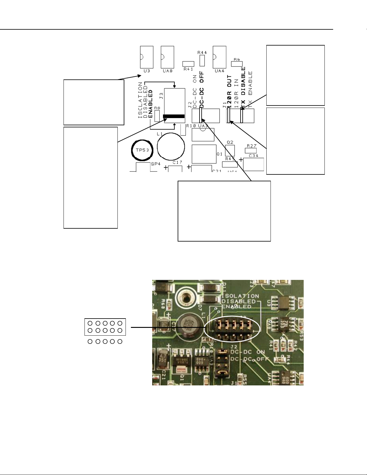
Access to the jumpers requires the removal of the lid of the SDM-CAN. Please
follow anti-static precautions during the removal of the lid and also when
changing the jumpers. Refer to FIGURE 2-1 for details of the jumper positions.
Labels are also provided in white writing on the circuit board.
If white jumper block not fitted then refer to FIGURE 2-2 for isolation enabled
and FIGURE 2-3 for isolation disabled.
6
Page 15
SDM-CAN PCB
Once the case lid
has been removed.
OBSERVE ANTISTATIC
PRECAUTIONS.
This jumper block
is used to select
isolated or nonisolated CAN-Bus
interface. The
jumper block can
be removed and
rotated so that the
red bar is nearest
to the mode arrow
head. The default
is for isolation
enabled.
SDM-CAN Datalogger-to-CANbus Interface
The DC-DC converter is off by
default. This will reduce power
consumption from the +12V
supply but means that the isolated
circuits must be powered
externally. To enable the DC-DC
converter move the jumper to the
DC-DC ON position.
Transmission of
CAN data is
hardware
disabled
by default. To
enable transmission,
move the jumper to
the TX enable
position.
The CAN-Bus
termination
impedance is
disabled by default.
If you need the bus
to be terminated,
then move the
jumper to the 120R
IN position.
FIGURE 2-1. SDM-CAN Internal Jumpers
FIGURE 2-2. SDM-CAN Isolation enabled (default)
7
Page 16
SDM-CAN Datalogger-to-CANbus Interface
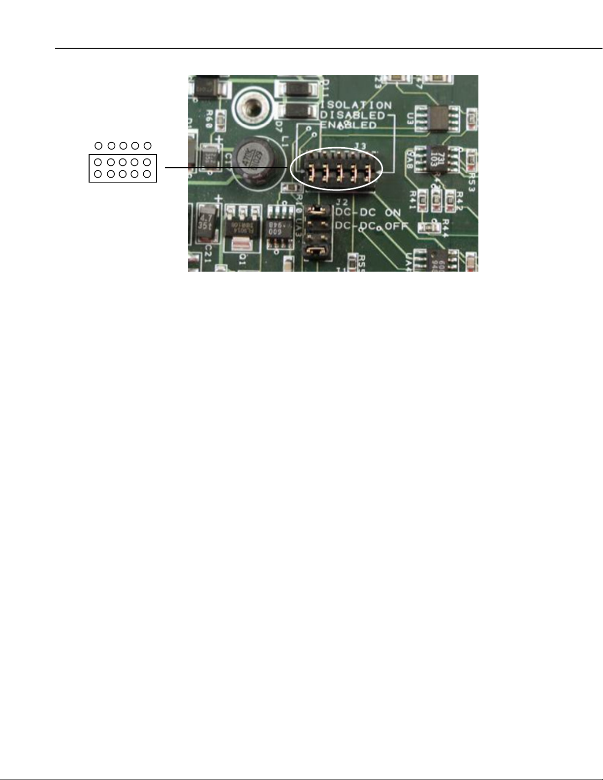
FIGURE 2-3. SDM-CAN Isolation disabled
2.3 Connection to the Datalogger and Power Supply
To allow communication between the SDM-CAN and a datalogger, firstly
connect it to the datalogger’s SDM port, and then connect to a 12V power
supply. Both the datalogger and the SDM-CAN 12V power supply must share
a common ground.
The SDM port is provided in different ways on different dataloggers:
CR10X and CR23X – use the C1, C2 and C3 control ports.
CR7 – a special SDM terminal block is provided as part of the SDM upgrade
kit. This terminal block is fitted on a small module adjacent to the 9 way
‘Serial I/O’ connector on the front of the 700 control module. The connections
are labeled C1, C2 and C3.
CR5000 – use the port connections labeled SDM-C1, SDM-C2 and SDM-C3.
CR9000 – connections are made via the 9 way, ‘CSI Serial I/O’ connector on
the 9080 PAM card. Pins 6, 7 and 8 are used as C3, C2 and C1 respectively.
Pin 2 is ground. Campbell Scientific offers connection modules for this port
which allow access to the SDM function as well as retaining normal function
of the serial port, please contact your local sales office for further details.
The SDM-CAN requires a nominal 12V power supply connection (7-26V)
rated at 150mA. Normally the datalogger supply can be used for this feed. A
connection to ground is also required. If the 12V supply is separate from the
datalogger, both the ground of the supply and datalogger must be connected
together.
8
The SDM and power connections are made to a black terminal block on the
left-hand side of the SDM-CAN interface. This terminal block has special
spring loaded terminals which are simple to use and highly resistant to
loosening in high vibration environments. To open the terminal simply insert
Page 17
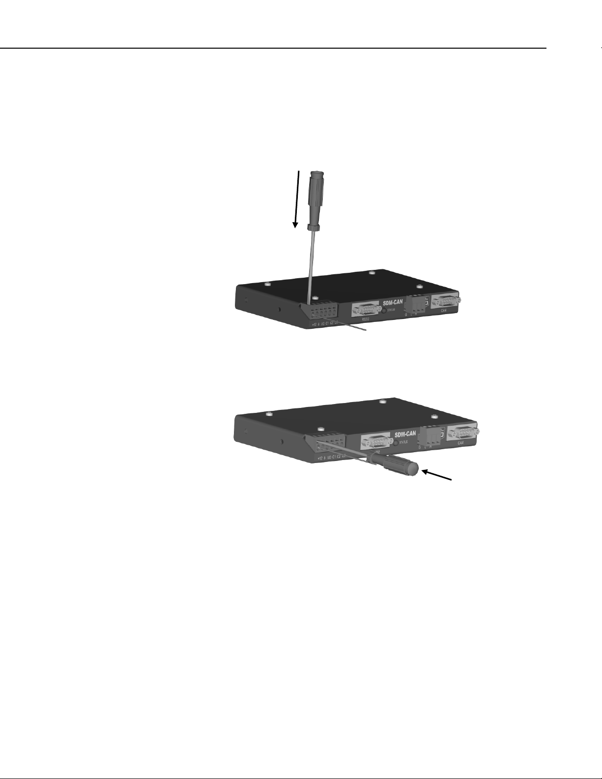
SDM-CAN Datalogger-to-CANbus Interface
the tip of a small flat blade screw driver (3mm width) into the rectangular hole
above the circular terminal hole. Push in the blade of the screwdriver until the
spring is released and the terminal opens. Insert the pre-stripped wire and then
remove the screwdriver. See FIGURE 2-4. If space is limited, as when the unit
is mounted in an enclosure etc., the screwdriver can be inserted into the front of
the terminal block to push open the spring, as shown in FIGURE 2-5.
FIGURE 2-4. Using the Spring Loaded Terminal Blocks (Top Option)
FIGURE 2-5. Using the Spring Loaded Terminal Blocks (Front Option)
Where you need to install more than one wire in a single terminal connector,
use only stranded wires and twist the wires together before inserting them in
the terminal. This type of terminal is not suitable for use with multiple solid
core wires unless the wires are joined externally, e.g. using a ferrule.
Route the wires from the SDM-CAN interface to the datalogger connections
using the shortest route. Avoid running them near cables which could cause
noise pickup. In noisy environments use low capacitance signal cable with an
overall foil screen, connecting the screen to the datalogger power ground.
Where multiple SDM devices are in use connect them in parallel to datalogger
SDM ports, making sure each device has a unique SDM address. Ensure that
the maximum cable length between the datalogger and the SDM-CAN does not
exceed 3 meters.
9
Page 18

SDM-CAN Datalogger-to-CANbus Interface
An additional I/O terminal is provided on the SDM-CAN for use with
dataloggers which support interrupt driven logging events. This might typically
be used to enable the rapid capture of time critical CAN data, where the I/O
port can be used to indicate to the datalogger that data has been captured and is
available for immediate collection (see below). In most applications this
function will not be used and the terminal need not be connected. Where it is
required, it should be connected to a digital input on the datalogger.
2.3.1 LED Status Indication
When power is applied to the SDM-CAN the red ‘STATUS’ LED will flash to
indicate the current status of the unit as a result of the power-up checks.
If the LED flashes once, the module has passed all power-up tests and should
operate correctly. The other flash sequences are shown below. Problems with
the operating system can normally be fixed by reloading the operating system.
Please contact Campbell Scientific if you are unable to resolve the problem.
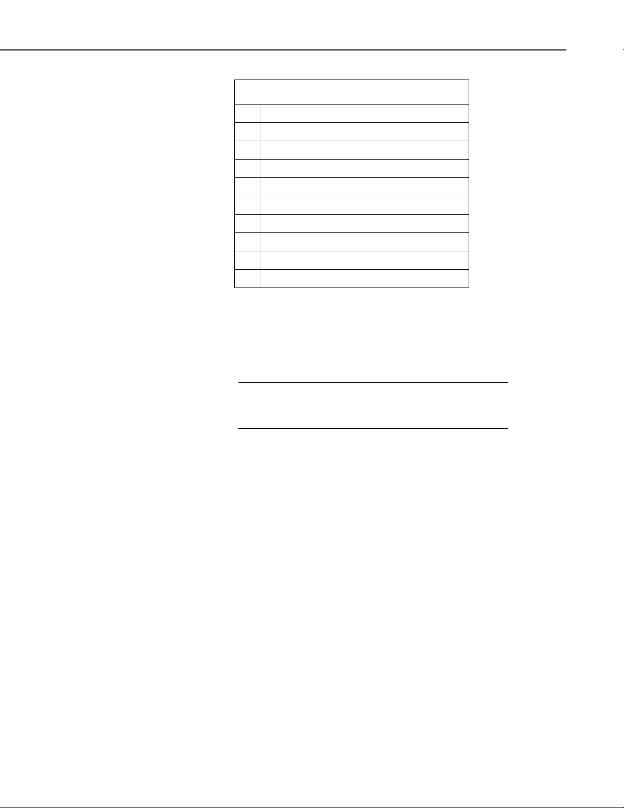
TABLE 2-2. LED Status Indication
Number of flashes Indication
1 SDM-CAN is ok.
2 OS signature bad.
10 OS downloaded has failed.
2.4 Connection to CAN-Bus.
The physical connection to the CAN-Bus is achieved by one of two methods
which is by either the 3 way un-pluggable screw terminals or the 9 pin ‘D’ plug
which conforms to CIA draft standard 102 version 2.
The basic connections of the CAN-Bus to the three-way terminal are CAN
High, CAN Low and 0V ground reference. The 3 way screw terminal is
marked as ‘G H L’ on the SDM-CAN case, where G=Ground, H=CAN High,
L=CAN Low.
The CIA, 9 pin, ‘D’ connector pin configuration is shown in TABLE 2-3.
10
Page 19
SDM-CAN Datalogger-to-CANbus Interface
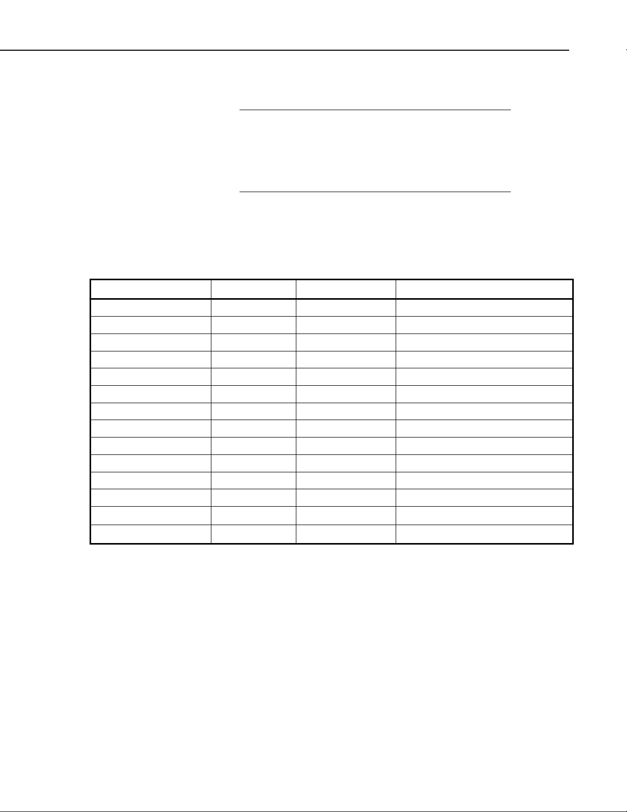
TABLE 2-3. CIA CAN Connector Pin Connections
Pin Function
1 Reserved, NOT INTERNALLY CONNECTED.
2 CAN Low.
3 CAN Ground.
4 Reserved, NOT INTERNALLY CONNECTED.
5 CAN Shield.
6 CAN Ground.
7 CAN High.
8 Reserved, NOT INTERNALLY CONNECTED.
9 CAN +5volts. Input or output (see text).
If the SDM-CAN hardware is configured (in either isolated or non-isolated
mode) with the DC-DC converter ON, then Pin 9 of the 9 pin ‘D’ connector
will provide +5V +/-10% at up to 40mA to any external device. If isolation is
enabled and the DC-DC converter is set to OFF then this pin acts as an input
for an external power supply capable of providing +5volts +/-10% at up to
100mA to provide power to the isolated circuitry of the SDM-CAN.
NOTE
The 3-way terminal block and CIA connector are connected in
parallel internally and are not two separate connections to
different CAN interfaces.
Please refer to the documentation for your CAN network to check the preferred
method of connection. For many applications various standards will apply
giving recommended practices for connection. Apart from the choice of
connector some standards recommend different ways of ‘tapping’ into CAN
networks and also recommend maximum lengths for ‘T’s or ‘stubs’ off the
network. For instance, at the highest baud rate of 1Mbit/s, ISO11898
recommends a maximum bus length of 40 m and a maximum stub length of 0.3
m. These lengths increase significantly at lower bit rates.
As discussed above you also need to consider:
• If the SDM-CAN should terminate the network
• If it should be configured in isolated mode
• If transmission should be enabled
• The source of power for the isolation hardware.
11
Page 20

SDM-CAN Datalogger-to-CANbus Interface
3. Programming CR10X, CR7 and CR23X Dataloggers to use the SDM-CAN
This section describes the programming methods used for the above
dataloggers to configure and use the SDM-CAN Interface. This section also
covers general principles and techniques which are relevant to the other
dataloggers.
3.1 General Principles
The SDM-CAN interface is controlled by instructions that the user enters in the
datalogger program. For the dataloggers covered by this section the Program
Instruction is number P118. Full details of the instruction are given below. This
sub-section has been written to introduce the parameters of Instruction P118
and how they allow you to control the different operations of the SDM-CAN.
The initial function is to configure the SDM-CAN interface when the
datalogger program is compiled. At this stage, the datalogger analyses the P118
parameters used by the program and sends the relevant commands to the SDMCAN to configure it to perform appropriate tasks.
The most common configuration task, at compile time, is to set up the SDMCAN to instruct it to filter out only the data frames of interest from all data
‘passing on the bus’.
The other configuration task done at this point is to specify the speed at which
the CAN-Bus is to operate. It is important to ensure the parameters which
define the speed are set correctly and all instructions have the same values
entered for these parameters otherwise either no data will be received, or you
risk corrupting data on the bus, if the SDM-CAN is enabled for transmission.
The next common function is to read data back from the SDM-CAN, to
decode it, and to store it in input locations once the program is running. A
single entry of P118 in the program can both configure the SDM-CAN during
program compilation and also cause data to be read back from the SDM-CAN
when that instruction is executed during normal program execution.
Similarly there is also a function which is used to send simple data from the
datalogger input locations onto the CAN-Bus via the SDM-CAN. Again a
single call of P118 can both configure and then transmit the data when the
program is running.
A more complicated version of this function is also possible where multiple
P118 instructions are used to build a transmit data frame within the SDMCAN, made up of a series of fixed or variable data values from input locations.
A subsequent P118 is used to instruct the SDM-CAN to transmit the frame
either immediately or in a response to a remote frame request from another
device.
12
Finally there are some special functions normally achieved by a single a call of
P118. One such function is used to change internal ‘switches’ within the SDMCAN which control its mode of operation, e.g. power mode, response to failed
transmissions etc. Similar functions also allow you to read back the settings of
these ‘switches’ into input locations and also to read and/or reset the number of
Page 21

CAN errors detected and to also determine the general status of the SDM-CAN
interface.
3.2 System Limitations
The SDM-CAN interface, in combination with a datalogger, has some
limitations of which you need to be aware:
1) Memory Allocation and P118
Firstly, as discussed above, when the datalogger compiles a program with
P118 in it, it sends commands to the SDM-CAN instructing it what to do
at run time. When it does this the SDM-CAN allocates some of its
memory (a ‘bin’) for each call of P118 in the program. Appendix A,
Principles of Operation, discusses the operation of these bins and other
buffers in the SDM-CAN in more detail. However, most users only need
to know that there is a limit of 128 bins in the SDM-CAN thus
constraining the number of instances of P118 for any one SDM-CAN to
128.
It is, of course, possible to have several SDM-CAN devices connected to
the datalogger(s), each with separate SDM addresses, and each with up to
128 calls of P118.
SDM-CAN Datalogger-to-CANbus Interface
2) Data Capture Limitations
Another limitation is the capability of the overall speed at which the
datalogger can pick up and transfer data values back to its memory. These
limitations do not arise within the SDM-CAN interface itself, as it uses a
high speed CAN interface along with a fast microprocessor. Data can
therefore be captured off the CAN-Bus at close to the maximum bus
loading at the maximum baud rate. However, the limitations arise from the
datalogger itself, both in terms of its capability to call P118 often enough
(especially when making other measurements) and also in its capability to
transfer the data from the SDM-CAN back into its memory over the SDM
communications port.
The exact throughput possible is determined by a very complicated
combination of variables, including the speed of the datalogger in
question, the program it is running, how many SDM devices are in use
and, to a lesser degree, other tasks it is running, e.g. communications
activity.
In practice, for fast data, it will not be practical to capture every single data
packet. However, the SDM-CAN will be used to sample the last reading it
received on the CAN-Bus before the datalogger requests data.
If a new data value has not been captured from the CAN-Bus since the last
value was transferred to the datalogger, the SDM-CAN can either be set to
always return the previous value captured (default) or it can be configured
(see the internal software switch settings below) to return the standard out
of range value to the datalogger, i.e. –99999 if the value has already been
read. This value will also be returned in the event of other errors including
communication errors between the datalogger and SDM-CAN.
13
Page 22

SDM-CAN Datalogger-to-CANbus Interface
Data stored in packets on the CAN-Bus can be encoded in a number of
different ways. The SDM-CAN itself can cater for many different types of
data, but there are some limitations imposed by the way in which the data
is stored in the datalogger. The prime limitation is that data read into the
datalogger is first converted into a 4 byte floating point format which can
only resolve, at most, 23 bits, or roughly 7 digits, of the decimal equivalent
of any number stored. Furthermore, when data is stored to final storage,
the resolution is truncated again to either 4 or 5 digits (with the exception
of the CR5000/9000 dataloggers which also support storage in IEEE4
format).
To avoid over-running the datalogger’s internal floating point resolution,
the maximum length of integer that the SDM-CAN can send or receive is
therefore limited to 16 bits. This limited resolution can cause problems
when reading CAN data where data is encoded as 32 or 64 bit integers.
The simplest solution, in those cases, is to read the value as a series of 16
bit integers written to separate input locations in the datalogger. These can
then either be combined once the data has been recovered to a computer
or, if some of the resolution is not needed, the data values can be
combined in the datalogger using its normal maths functions. You must
bear in mind, however, the limitations of the 4-byte floating point
calculations and the output resolution of the datalogger.
The CAN standard also allows some types of data to be spread across
several data packets, where those data packets all have the same identifier.
Such data normally would consist of fixed identifiers stored as ASCII data,
which do not normally have to be logged. Reliably capturing such data
with the SDM-CAN is not possible, with the current software, unless the
sequential packets are transmitted relatively slowly. Please contact
Campbell Scientific for further information if you have a requirement to
do this.
14
3) When transmitting CAN frames from the SDM-CAN there are situations
where some frames are not transmitted. This is because the SDM-CAN has
a two layer buffer for transmitted frames. This allows a frame to be
transmitted whilst a new frame is being built. However if your program
tries to send frames too quickly, before earlier frames are sent, the frames
will be overwritten and lost.
This scenario generally does not happen with CR10X / CR23X loggers as
they are not fast enough. But with the CR5000 / CR9000 loggers it is
possible to overrun the double buffer especially in pipe line mode if you
are transmitting more than 2 frames per scan. It is recommended to use
sequential mode in this case as it allows a delay between CAN-BUS
instructions.
3.3 The Datalogger Instruction
The instruction used by all of the dataloggers covered in this chapter is
Instruction 118. The structure of the instruction and parameter types is shown
below. This structure is given in the same format that normal instructions are
shown in the datalogger manuals. Please refer to the datalogger manual for a
Page 23
SDM-CAN Datalogger-to-CANbus Interface
description of the data types, entry of the instruction and how to index (‘--’)
parameters.
NOTE
In some previous versions of datalogger operating systems,
Instruction 118 was used for the now obsolete OBDII interface.
Older datalogger manuals and Edlog help systems may still refer
to this instruction. Please make sure you are using a version of
the operating system that supports P118 and refer to a more
recent datalogger manual or Edlog help system.
It will be apparent for some functions of P118 that some parameters are not
relevant or have no function. In these cases simply leave the parameter(s) at
their default value(s) which is normally zero.
3.3.1 Instruction 118: SDM-CAN
PARAM. NUMBER DATA TYPE DESCRIPTION RANGE
01: 2 SDM address 00..33
02: 2 TQUANTA 0-63
03: 2 TSEG1 0-15
04: 2 TSEG2 0-7
05: 4 ID bits 0-10 0-2047 ‘--’ Set 11bit ID.
06: 4 ID bits 11-23 0-8191
07: 2 ID bits 24-28 0-31
08: 2 Data type 0-33
09: 2 Start bit number 0-64, ‘--’ Left-hand referenced LSB.
10: 2 Number of bits 0-64, ‘--' Enable Interrupt mode.
11: 4 Number of values 0-99
12: 4 Input Location
13: FP Multiplier
14 FP Offset
3.3.2 SDM Address (Parameter 01:)
This parameter should match the SDM address set by the address switch on the
side of the module to which this instruction applies. Please see Section 2.1,
Address Switch Configuration, above, for more details. Also see the section
below, regarding the special function of address 33.
3.3.3 TQUANTA, TSEG1, TSEG2 (Parameters 02:, 03:, 04:)
These parameters are used to set the bit rate and other timing parameters for the
CAN-Bus network. On some networks the relationship between some of these
parameters is predefined and just one parameter, the baud rate, is quoted. For
maximum flexibility, though, the user is given access to all of the relevant
parameters. TABLE 3-1 gives some typical values of the parameters for a
15
Page 24

SDM-CAN Datalogger-to-CANbus Interface
b
range of baud rates. However, be sure to check that these are correct for your
specific network before using them.
The parameters are entered as integer numbers which define various times that
control when the binary data is sampled by the CAN hardware. The following
discussion and nomenclature is common to the set-up of most CAN controller
chips. If you are not familiar with CAN at this level please seek the advice of
someone who is familiar with your network to determine these parameters.
The overall speed of the network is specified by the baud rate, in bits per
seconds, which define the time per bit (
t
= 1 / baudrate
bit
Within the time period for each bit the CAN standards define three different
time segments which ultimately control when the CAN hardware samples the
signal.
This is often shown in a diagram, thus:
t
) by the simple relationship:
bit
1 time-quanta
Bit time (t
S-SG PROP_SEG PHASE_SEG1 PHASE_SEG2
t
t
(tq)
TSEG1
)
it
Sample point
t
The bit time is divided into time-quanta (
time- quantum in the bit time. The
t
), of which there are between 8-23
q
(in seconds) used by the SDM-CAN is
q
set by the scaling factor TQUANTA (parameter 02). This is the parameter that
largely determines the baud rate. To work out a suitable value of TQUANTA,
t
knowing the required
TQUANTA = t
q
, the following equation is used:
q
* 8*106
The first time segment is known as the synchronization segment (S-SG) and
by convention is one time-quanta long.
This is followed by two segments known as the propagation segment and phase
segment one. These are determined by the characteristics of the network and
other devices on the network. The total of these two time segments determines
the time
TSEG2
when the SDM-CAN samples the data bit and is known as t
segment is known as phase segment two or t
TSEG2
TSEG1
. The final
16
Page 25

SDM-CAN Datalogger-to-CANbus Interface
The relationship between these times is summarized by:
t
bit=tq+tTSEG1+tTSEG2
t
(in seconds) is set using the scaling factor TSEG1 (parameter 03), the
TSEG1
value of which is calculated using the following equation:
TSEG1 = t
t
is set using scaling factor TSEG2 (parameter 04) the value of which is
TSEG2
TSEG1
/ tq
calculated using:
TSEG2 = t
TSEG2
/ tq
When determining the settings of these parameters it is important to ensure that
the size and total number of t
exactly matches the baud rate at which the
q
network is to run, as the tolerance allowable is normally quoted as +/-1.5%.
The relative settings of TSEG1 and TSEG2 are not so critical as they control
when the hardware samples the data value and there is normally quite a wide
tolerance over which this will work.
If no data other than the baud rate of a network is available a simple ‘rule of
thumb’ is to set the parameters such that there are at least eight time-quanta in
the span of the bit width and that the sample point is 80% through the bit
width.
TABLE 3-1. Typical settings of the CAN Speed Parameters
Baud rate TQUANTA TSEG1 TSEG2
1M 1 5 2
800 K 1 7 2
500 K 2 5 2
250 K 4 5 2
125 K 8 5 2
50 K 16 7 2
20 K 40 7 2
NOTE
The same three values for these parameters should be used in
every call of the P118 instruction in the datalogger program.
3.3.4 ID (Parameters 05:, 06:, 07:)
A CAN data frame includes an identifier (ID) which is used by devices on the
network to identify each type of packet on the network. Some standards reserve
certain IDs or ranges of IDs for specific functions. The J1939 SAE standard for
instance reserves certain parts of the ID to identify the type of data, its priority
and its origin (see Appendix C, Application of the SDM-CAN on Networks
Complying with the J1939 SAE Standards, for a discussion of this standard and
use with the SDM-CAN). The SDM-CAN is, however, transparent to any
17
Page 26

SDM-CAN Datalogger-to-CANbus Interface
special meaning of the ID; each packet is only referenced by the full ID. The
CAN 2.0A standard uses an ID with 11 bits, while CAN 2.0B uses 29 bits.
When entering IDs into Instruction P118, three parameters are used. This is
because the ID size, in number of bits, is too large to be encoded into a single
parameter.
The first ID parameter (parameter 05) sets bits 0..10, entered as a number
between 0 and 2047. This parameter also determines whether an 11-bit or a 29bit Identifier is set. If you index this parameter then an 11bit Identifier is set;
the following two parameters are then irrelevant and are normally left at zero.
The second ID parameter (parameter 06) encodes bits 11..23 entered as 0 to
8191. The third ID parameter (parameter 07) is for bits 24 to 28 entered as 0 to
31.
NOTE
CAN networks either work with 11 or 29 bit IDs. As a general
rule you cannot have packets with different length IDs on the
same network. Therefore make sure parameter 05 specifies the
same length ID for all calls of P118.
3.3.5 Data Type (Parameter 08:)
This parameter determines the type of data involved and/or the type of function
this call of P118 will perform. The data type parameter is entered as a two-digit
parameter in the range of 0-33. A summary table of the data types described
below is given in Appendix B, A Summary of Data Types, of this manual for
quick reference.
As a general rule, this function is applied only to data packets with the ID
specified in parameters 05..07. The action applies to a certain number of bits
within the data frame that is specified in parameter 10, starting at the bit
specified in parameter 09. In some cases the number-of-bits parameter is
overridden implicitly by the data type specified, e.g. IEEE4 data is always 32
bits in length. For integer values, the longest integer you read or send from one
datalogger input location is 16 bits as a result of limitations in the datalogger.
See Section 3.2, System Limitations, above for an explanation and workarounds.
For data types that read or set status, switches or error codes, only the input
location parameter, multiplier and offset are used. Other parameters can be set
to zero.
18
As defined by the CAN standard, data is always encoded or decoded on the
assumption that the least significant bit is transmitted last or is on the ‘righthand side’ of a data frame. The data frame can be from 0 to 64 bits in length,
but is normally a multiple of 8-bit bytes. This means there are typically 0-8
bytes in the data frame.
Please refer to Appendix D, Examples of CAN Data Frames and Data
Encoding and Decoding, for examples of typical data frames and how to
decode data within them. Appendix D, Examples of CAN Data Frames and
Data Encoding and Decoding, also contains diagrams to show the method of
pointing to the start bit within the data frame.
Page 27

For convenience the start bit can be referenced from either end of the frame
(see parameter 09 below), but this does not change the direction in which data
is encoded or decoded. Within a byte the MSBit is always first (on the left).
Where the number-of-values parameter (parameter 11) is greater than one, the
same function is applied to successive sections of the data frame, moving
towards the ‘left’ of the frame. Data values are read to, or written from,
successive input locations in the datalogger.
The data types can be grouped into different type of functions, as follows:
3.3.5.1 Collect and retrieve a data value:
This function programs the SDM-CAN to capture a particular data packet and
pass specific data from the data frame within that packet back to the
datalogger.
Parameter Value Data Type
1 Unsigned integer, most significant byte 1st.
2 Unsigned integer, least significant byte 1st.
3 Signed integer, most significant byte 1st.
4 Signed integer, least significant byte 1st.
5 4 byte IEEE floating point number, most significant byte 1st.
6 4 byte IEEE floating point number, least significant byte 1st.
SDM-CAN Datalogger-to-CANbus Interface
3.3.5.2 Build a data frame for transmission:
The data will be sent to the SDM-CAN where it is written into a working 8byte buffer in memory. The data is written starting at the bit position
determined by parameter 09 and the number of bits stored by parameter 10.
When the data type parameter is set in the range of 7..12, the data is written to
the buffer directly, i.e. it overwrites any previous data in that memory (see also
types 13..18).
Once the buffer is complete, after using other P118s with this range of data
types to construct the desired data frame, it is sent out onto the CAN-Bus by a
further call of P118 with parameter 08 set to 25 or 26 (see below).
Parameter Value Data Type
7 Unsigned integer, most significant byte 1st.
8 Unsigned integer, least significant byte 1st.
9 Signed integer, most significant byte 1st.
10 Signed integer, least significant byte 1st.
11 4 byte IEEE floating point number, most significant byte 1st.
12 4 byte IEEE floating point number, least significant byte 1st.
Setting parameter 08 in the range of 13..18 has the same function as in
the7..12 range, except that the data values written are logically ‘OR’ed with
19
Page 28

SDM-CAN Datalogger-to-CANbus Interface
values previously written into the memory buffer. This allows complex bit
patterns to be defined, sometimes changing only as little as one bit at a time.
Parameter Value Data type
13 Unsigned integer, most significant byte 1st.
14 Unsigned integer, least significant byte 1st.
15 Signed integer, most significant byte 1st.
16 Signed integer, least significant byte 1st.
17 4 byte IEEE floating point number, most significant byte 1st.
18 4 byte IEEE floating point number, least significant byte 1st.
3.3.5.3 Transmit individual data values onto the CAN-Bus:
This range of parameter values instructs the datalogger to send a data value to
the SDM-CAN in the format specified; it is loaded into the specified point in a
data frame and then immediately transmitted onto the CAN-Bus. Bits within
the data frame that are not set are left at zero. The data frame length is set to the
minimum size (in whole bytes) required to hold the type of data value
specified.
Parameter Value Data Type
19 Unsigned integer, most significant byte 1st.
20 Unsigned integer, least significant byte 1st.
21 Signed integer, most significant byte 1st.
22 Signed integer, least significant byte 1st.
23 4 byte IEEE floating point number, most significant byte 1st.
24 4 byte IEEE floating point number, least significant byte 1st.
3.3.5.4 Transmit a previously built data frame on to the CAN-Bus (type 25):
When parameter 08 is set to 25, P118 will cause the datalogger to tell the
SDM-CAN to transmit a previously ‘built’ data frame which is stored in the
memory buffer for this packet ID (see data types 7..18 above).
The length of the data frame transmitted is determined by parameter 10. If
number of bits is less than a complete number of full bytes (1-8) then the
number of bytes sent will be rounded up and all unused bits will be set to zero.
The data start bit position will normally be set to one so the data frame starts at
the beginning of the memory buffer. However, you can enter a value greater
than one to allow part of the buffer to be transmitted, which can simplify some
binary masking operations.
20
The memory buffer is left unchanged after transmission.
Page 29

SDM-CAN Datalogger-to-CANbus Interface
3.3.5.5 Set-up previously built data frame as a Remote Frame Response (type 26):
When parameter 08 is set to 26, P118 will configure the SDM-CAN to use a
previously ‘built’ data frame as remote frame response for packets of the
specified ID. The length and start positions are specified as for data type 25.
3.3.5.6 Read error counters (type 27):
This will return 4 values, in successive input locations starting at the location
set by parameter 12, which show certain errors the SDM-CAN has recorded.
The errors are written in the following order: transmit, receive, overrun and
watchdog counts. Each is a count from 0 to 255.
The transmit, receive and overrun counters are measures of the errors on the
CAN-Bus network as defined by the CAN standards. If the transmit counter
reaches 255 then the CAN device goes into a ‘bus-off’ state, where it
effectively disconnects itself from the network.
If the SDM-CAN switches to the ‘bus-off’ state, any further reads of the error
counters will show the transmit counter fixed at 127. The counters then need to
be reset to enable further use of the SDM-CAN (see data type 28, below). If
this situation occurs on a regular basis, firstly check the datalogger program
(P118 parameters). If these are correct, check the structure and design of the
network.
The watchdog counter only increments (and is automatically reset) when the
SDM-CAN ‘crashes’ either due to an internal software error or a hardware
fault. Please contact Campbell Scientific for further advice.
3.3.5.7 Read and reset the error counters (type 28):
This functions in exactly the same way as type 27 except that after reading the
error counters they are reset to zero. This will also re-enable the SDM-CAN
interface to the CAN-Bus if it has automatically entered the ‘bus-off’ state.
When the counters are reset, the CAN controller chip enters a special state and
waits until it sees a period equal to 11 successive bits of inactivity on the CANBus before it returns to the normal ‘on-line’ state. Therefore this function
should not be called too frequently otherwise data may be lost.
3.3.5.8 Read status (type 29):
This data type instructs the datalogger to request the current status of the SDMCAN and writes the results into a single, specified, input location. The status is
encoded within that location in the format ‘abcd’ where each letter is a digit in
the range 0 to 9 indicating a different type of status information.
Status ‘a’: 0 This digit is currently unused.
Status ‘b’: 0 This digit is currently unused.
Status ‘c’: 0 This digit is currently unused.
Status ‘d’: 0 Bus-On; the SDM-CAN is involved in bus activities. All of
the error counters are less than 96.
21
Page 30

SDM-CAN Datalogger-to-CANbus Interface
1 Bus-On; the SDM-CAN is involved in bus activities. One
2 Bus-Off; the SDM-CAN is not involved in bus activities.
3 Bus-Off; the SDM-CAN is not involved in bus activities.
See data type 28 above for details of the error counters and how to reset them.
3.3.5.9 Read the signature and version number of the SDM-CAN operating system (type
30):
This will return the OS signature and the OS Version number in separate
locations. If the SDM-CAN detects that the OS signature is bad then zero will
be returned.
3.3.5.10 Send Remote Frame Request (type 31):
A special type of CAN frame, called ‘remote frame request’ is transmitted with
the CAN ID specified.
of the error counters is equal to or greater than 96.
All of the error counters are less than 96.
One of the error counters is equal to or greater than 96.
3.3.5.11 Set SDM-CAN internal software switches (type 32):
This data type instructs the datalogger to change some internal software switch
settings that control the way it works. The new switch settings are read from a
specified input location. The settings are encoded within that location in the
format of a four digit number. For explanation purposes the four digits are
represented as ‘abcd’ where each letter is a digit in the range 0 to 9 which
indicates a different type of switch setting.
Once set the switches remain set until changed by another call of P118 or on
loading a different program. Therefore it is only necessary to call a P118 to set
these switches once, after program compilation, or when a switch needs to be
changed using a call of P118 within an IF..THEN program construct (see the
program examples below).
Switch ‘a’: 0 This digit is currently unused; enter zero
Switch ‘b’: 0 SDM-CAN returns the last value captured from the
network, even if read before (Default)
1 SDM-CAN returns –99999 if a data value is requested by
the datalogger and a new value has not been captured
from the network, since the last request.
2-9 Currently unused
Switch ‘c’: 0 Disable I/O Interrupts (Default) – see Section 3.4.1,
Interrupts Using the I/O Connection
22
1 Enable I/O Interrupts, pulsed mode
2 Enable I/O Interrupts, fast mode
Page 31

SDM-CAN Datalogger-to-CANbus Interface
3-7 Currently unused
8 Set low power standby mode. The SDM-CAN cannot
wake from this state as a result of CAN-Bus activity.
Setting this switch to any other value will bring the SDMCAN out of standby.
9 Leave this switch setting unchanged
Switch ‘d’: 0 Listen only mode, no CAN transmission or
acknowledgement to a correctly received CAN frame is
possible. The SDM-CAN runs in ‘Error Passive’ mode
(Default).
1 One shot transmission, no re-transmission will occur in
the event of loss of arbitration or error. Frames received
correctly from an external node are acknowledged
2 Self-reception. A frame transmitted from the SDM-CAN
that was acknowledged by an external node will also be
received by the SDM-CAN but no re-transmission will
occur in the event of loss of arbitration or error. Frames
received correctly from an external node are
acknowledged
3 Normal, re-transmission will occur in the event of loss of
arbitration or error. Frames received correctly from an
external node are acknowledged. This is the usual setting
to use if the SDM-CAN is to be used to transmit data.
4 One shot transmission and self test mode. The SDM-CAN
will perform a successful transmission even if there is no
acknowledgement from an external CAN node. Frames
received correctly from an external node are
acknowledged
5 Self-reception and self test mode. The SDM-CAN will
perform a successful transmission even if there is no
acknowledgement from an external CAN node. Frames
received correctly from an external node are
acknowledged. The SDM-CAN will receive its own
transmission
6 Normal and self test mode. The SDM-CAN will perform a
successful transmission even if there is no
acknowledgement from an external CAN node. Frames
received correctly from an external node are
acknowledged.
7 Similar to switch setting 'd-3' , but this setting is
'remembered' at power-up. During power-up, the SDMCAN will acknowledge all valid messages.
NOTE: This setting relies on the datalogger having set up
the SDM-CAN before use.
8 Not defined
9 Leave this switch setting unchanged
23
Page 32

SDM-CAN Datalogger-to-CANbus Interface
NOTE
3.3.5.12 Read SDM-CAN internal switches (type 33):
Please refer to the CAN standards and your own network
documentation for a more detailed explanation of the switch ‘d’
modes. It is important to choose the correct setting when the
SDM-CAN is required to transmit data. Also remember to check
the jumper settings inside the SDM-CAN if enabling
transmission, as the default setting is for transmission to be
disabled in hardware.
This data type returns the internal switch settings, into a specified input
location. The switch values shown are encoded in the same way as they are set
(see type 34 above), with the exception that a switch setting of 9 is reserved to
show an undefined error (please contact Campbell Scientific if such an error
occurs).
3.3.6 Start Bit Number (Parameter 09:)
The start bit number is used to point to the least significant bit (LSB) of the
data value within the CAN data frame to which this instruction relates. Within
CAN data frames there is no general standard as to the order or format of the
binary data. ISO11898 does specify that data should be sent with the most
significant bit (MSB) first, least significant bit (LSB) last. Most diagrams show
the MSB on the left and the LSB on the right. However, some users may find
the start point for the data is referenced in the opposite fashion, i.e. as a count
from the left side of the frame, and so the SDM-CAN supports both methods of
referencing the start point.
By default the SDM-CAN follows the ISO standard and the LSB is referenced
to the right-most bit of the frame. The bit number can range from 1 to 64 as
there are up to 64 bits in a CAN frame. If the parameter is indexed, (marked ‘-’) then the reference is changed to point to the LSB relative to the left-hand
most bit of the frame. Please note, though, that choosing this option does not
have any automatic affect on the type (direction) of encoding or decoding used
– it only changes the method of pointing to the LSB.
NOTE
When entering the start bit, you should always point to the
position of the least significant bit of the data to be
decoded/encoded. Please refer to Appendix D, Examples of CAN
Data Frames and Data Encoding and Decoding, for diagrams
and examples of typical data types.
3.3.7 Number of Bits (Parameter 10:)
This relates to the number of bits to use in this transaction. This number can
range from 1 to 64 as there are up to 64 bits in a CAN frame. If this parameter
is indexed (‘--’) then, when a new value is received, the SDM-CAN, relevant to
this particular call of Instruction P118, will pulse the I/O port to indicate to the
datalogger that the data has been captured and can be read (see below).
24
Page 33

NOTE
For some data types this parameter will be overridden by a fixed
number of bits required by the data type; even so the interrupt
setting can still be set. For integer values, the longest integer you
can read or send from one datalogger input location is 16 bits as
a result of limitations within the datalogger (see Section 3.2,
System Limitations, above for an explanation and work-arounds.
3.3.8 Number of Values (Parameter 11:)
This is the number of values that will be transferred to or from the datalogger
in one operation. For each value transferred, the number of bits (parameter 10)
will be added to the start bit number (parameter 9) when the start point is
referenced to the right-hand side of the data frame. If referenced to the lefthand side, then the number of bits is subtracted from the current bit position.
The consequence of this is that successive values are always from right to left
in the frame.
3.3.9 Location (Parameter 12:)
This is the start input location where data will be read from or stored to. For
any remaining values/repetition, each value will be read from, or stored into,
the next incremental location.
SDM-CAN Datalogger-to-CANbus Interface
3.3.10 Multiplier (Parameter 13:)
The data written to, or read from, an input location is multiplied by this
parameter.
3.3.11 Offset (Parameter 14:)
The data written to, or read from, an input location has this offset parameter
added to it.
3.4 Advanced Programming Techniques
3.4.1 Interrupts Using the I/O Connection
The I/O port can be used to signal to a datalogger that specific data has been
captured, by the SDM-CAN, from the CAN network and is available for
collection by the datalogger.
The main application for this is where CAN data needs to be captured at a
much faster rate than the normal scan interval of the datalogger and the
requirement is to capture as many CAN packets as possible. In this case the
interrupt facility can be used to give capture of the CAN data as a higher
priority over the normal scheduled measurement tasks, allowing the data to be
captured at the highest rate possible.
The interrupt facility can also help solve the conceptual problem of capturing
data into the datalogger from another system (one of the other devices on the
CAN-Bus) which is running on a different asynchronous clock from the
datalogger itself. This problem needs some consideration in all applications
25
Page 34

SDM-CAN Datalogger-to-CANbus Interface
except those where the datalogger can be made the master (i.e. where it
requests data from the remote devices when its needs the data).
In other applications one has to cater for the possibility that data might not be
available from the CAN network when the datalogger clock causes the
datalogger to run its program. This can happen even when the CAN data is
being transmitted at the same rate as the datalogger is running, simply because
the two system clocks drift relative to each other. The interrupt facility allows
you to ensure that data can be captured at the highest possible rate, but you still
have to use special programming and/or data analysis techniques to
synchronize the data with other measurements. The main problem is that the
interrupt function might run more time stamps to the faster measurements in
order to allow normal data analysis.
To enable the interrupt facility on the SDM-CAN you need to index (--) the
program on the number-of-bits parameter (10) of the particular P118
instruction that you want to cause the interrupt when data is received. The
following rules apply:
• The interrupt function only applies to data types which read data from
the CAN-Bus.
• You can mark more than one P118 instruction to generate an interrupt,
but you will then need to read data from all the possible data types
which are indexed, as one or more may contain a new value and all
new data must be read before the interrupt is cleared.
• With the CR10X and CR23X dataloggers you should ensure that all of
the P118 instructions which are marked to cause an interrupt are in the
same interrupt subroutine, normally number 98. Other dataloggers do
not currently support the interrupt subroutine mechanism, but can be
used in a similar mode by polling the digital input connected to the
SDM-CAN I/O port, and only actually reading the data when the port
is high.
As well as indexing parameter 10 of the instructions, you also have to enable
the interrupt function by changing an internal software ‘switch’ in the SDMCAN. This is done by calling P118 with data type 32, and setting digit ‘c’ to 1
or 2. (See above).
A switch value of 1 causes the interrupt function to operate in the following
way:
a) With no Interrupt pending the I/O port is pulled low with 100Kohms.
b) With an interrupt pending,
first check that no other device is holding the port high and then pulse
high for 50 milliseconds. If the I/O terminal is held at +5V by another
peripheral it will wait until the I/O terminal goes low and has been low for
50 milliseconds before trying to drive it high to +5V again. The I/O line
has a drive impedance of 1Kohms.
i.e. data has been captured, the SDM-CAN will
26
This method of driving the I/O line allows multiple SDM-CANs and other CSL
products that support the I/O line to be wired in parallel. One consequence of
the above technique, though, is that there will be a gap of up to 50 milliseconds
Page 35

SDM-CAN Datalogger-to-CANbus Interface
following the end of one interrupt before the SDM-CAN will raise the port for
another interrupt. This could be a limitation in high speed data capture
applications, hence the need for switch 2.
When switch 2 is set, the SDM-CAN responds immediately to data receipt and
raises the port as soon as data has been received, filtered and processed. The
SDM-CAN will only lower the line again permanently when the datalogger
reads the data out of the SDM-CAN that caused the interrupt. To prevent
problems with some events which might cause the datalogger to miss
interrupts, the SDM-CAN will pulse the I/O port low for 1 ms after 50 ms, take
the line high and then repeat this cycle until all the relevant data has been read.
Using this switch setting will provide the quickest way of capturing data but
may not work with other devices sharing the datalogger interrupt port.
NOTE
To ensure proper configuration of the SDM-CAN by the
datalogger for interrupt driven applications, it will pulse its I/O
port on and off at 50ms intervals for 6 seconds after power-up or
program recompilation.
3.4.2 Group Trigger
The group trigger function provides a mechanism to synchronize the data
capture by one or more SDM-CAN (and some other SDM devices too).
This mode is enabled when an SDM-Group Trigger (P110) instruction is
encountered. When this instruction runs, it broadcasts a special SDM message
which causes all the SDM-CAN devices to copy the last data values captured
from the CAN-bus into the working data buffers, and no further updates are
allowed until P110 runs again (normally at the next execution of the program
table). P118 instructions will read the locked values which are all sampled at
once.
This SDM-Group trigger command is normally positioned at the beginning of
the program table to lock all data samples exactly to the start of the scan
interval. It should be remembered, however, that in the case of the SDM-CAN
it will simply lock these values to the last values captured which could already
have been transmitted some time earlier.
The SDM-Group trigger instruction actually broadcasts its message to SDM
address 33
Group trigger command is to be used. This effectively reduces the number of
SDM peripherals that support global trigger to 15 units.
(base 4), which prevents this address being available if the SDM-
4
3.4.3 Frame buffers with filtering and triggering
Operating systems V3 include the ability for the user data logger program to
attach a buffer of 256 frames to any receiving CAN ID up to a limit of 25
different ID’s.
NOTE
If the user program tries to allocate more than 25 buffers then the
additional buffer allocations will be ignored.
27
Page 36

SDM-CAN Datalogger-to-CANbus Interface
Each buffer can be configured as a standard ring buffer with no trigger or filter
associated with it. The buffer can also be set to start to capture data when a
predefined trigger pattern is encountered within the CAN data, or it can filter
and buffer only the CAN frames that have some part of the data that fits a
pattern.
To configure a filter or trigger two masks are used. The first is user defined as
a 64 bit include AND mask applied to the CAN data of the CAN ID of interest.
A second 64 bit user defined pattern is compared with the CAN data and when
it matches the results of the previous `AND’ operation the buffer will either
trigger or filter CAN data of a specific ID until the buffer is full.
The buffer is a fill and stop ring buffer so if the buffer is full no more data will
be stored until the logger reads a frame and makes room for another frame to
be stored. With no mask and pattern bits set in trigger mode the buffer will
trigger on any frame and behave as a normal ring buffer. This is useful for
collecting fast back to back bursts of packets as the logger can collect them
later in the knowledge the SDM-CAN will have captured up to 256 packets and
stored them in its buffer.
3.4.3.1 Setup of Mask and Filter / trigger
To implement this buffer function the build data frame Data type (7) is used as
follows:
a) If “start bit number” (parameter 9) is NON-zero then data type 7 will build
a data frame as normal.
b) If (parameter 9) is zero, the number of bits (parameter 10) is set to 8 with
index (--) NOT SET and number of bytes (parameter 11) is set to 16 then
an `Include mask’ and `Filter mask’ can be set at run time. The first 8
bytes are the Include mask mapped directly as a 64 bit frame with the first
byte as the right most byte of the data frame. The second 8 bytes is the
Filter mask mapped directly as a 64 bit frame with the first byte as the
right most byte of the data frame. This instruction will also flush the
buffer. This is used to create the buffer and attach it to a particular ID.
c) If (parameter 9) is zero, the number of bits (parameter 10) is set to 8 with
the index (--) SET and number of bytes (parameter 11) is set to 16 then an
`Include mask’ and `Trigger mask’ can be set at run time. The first 8 bytes
are the Include mask mapped directly as a 64 bit frame with the first byte
as the right most byte of the data frame. The second 8 bytes is the Trigger
mask mapped directly as a 64 bit frame with the first byte as the right most
byte of the data frame. This instruction will also flush the buffer and reset
ready for trigger. This is used to create the buffer and attach it to a
particular ID.
28
3.4.3.2 Reading / Polling Buffer
To implement this buffer function the read switch Data type (33) is used as
follows:
a) If “start bit number” (parameter 9) is zero then data type 33 will read the
internal switches as normal.
Page 37

b) If (parameter 9) is one, the number of bits (parameter 10) is set to 8 with
the index (--) NOT SET and number of bytes (parameter 11) is set to zero
then one CAN frame will be transferred from the buffer to the working
buffer ready for normal data collection using Data Types 1-6. Also the
number of CAN frames stored in the buffer will be stored in a logger
location specified by this instruction.
c) If (parameter 9) is one, number of bits (parameter 10) is set to 8 with the
index (--) SET and number of bytes (parameter 11) is set to zero then only
the number of CAN frames stored in the buffer will be stored in a logger
location specified by this instruction. This instruction would generally be
used for polling the buffer.
3.4.3.3 Basic Sequence of Buffer Usage:
1. Initialize buffer and trigger event or filter using an SDM-CAN instruction
with data type 7.
2. Wait long enough or poll the buffer until enough CAN frames are
collected using an SDM-CAN instruction with data type 33.
3. Transfer a CAN frame from the buffer to the working buffer using an
SDN-CAN instruction with data type 33.
SDM-CAN Datalogger-to-CANbus Interface
4. Parse the CAN data frame using the normal SDM-CAN data types 1-6.
5. Repeat from (3) until you have collected and parsed all the CAN frames
you require from the buffer.
6. Do other processing ………..
7. Repeat from (1) to collect another set of CAN frames.
3.5 Program Examples
Examples of specific instructions which decode/encode CAN data are shown in
Appendix C, Application of the SDM-CAN on Networks Complying with the
J1939 SAE Standards. This section gives some general examples of program
constructs which show the general principles of operation.
3.5.1 Reading CAN Data
The following example reads a 16 bit engine speed value from a CAN network
running at 250K baud.
;{CR23X}
;
*Table 1 Program
01: 1.0 Execution Interval (seconds)
;Retrieve Data from CAN network
29
Page 38

SDM-CAN Datalogger-to-CANbus Interface
1: SDM-CAN (P118)
1: 0 SDM Address
2: 4 Time Quanta
3: 5 Tseg1
4: 2 Tseg2
5: 1024 ID Bits 0..10 (-- for 11-bit CAN ID)
6: 7680 ID Bits 11..23
7: 12 ID Bits 24..28
8: 2 Rx, unsigned int, LSB 1st
9: 33 Start Bit No.
10: 16 No. of Bits
11: 1 No. of Values
12: 1 Loc [ Eng_Spd ]
13: 0.125 Mult
14: 0.0 Offset
*Table 2 Program
02: 0.0000 Execution Interval (seconds)
*Table 3 Subroutines
End Program
NOTE
The above example uses the J1939 standard to define the ID
parameter and value position in the data frame. Please refer to
Appendix C, Application of the SDM-CAN on Networks
Complying with the J1939 SAE Standards, for an explanation of
the application of the SDM-CAN interface to networks
complying to the J1939 standard.
3.5.2 Simple CAN Data Transmission
The following example transmits a 16 bit temperature value to a CAN network
running at 500K baud.
;{CR10X}
;
*Table 1 Program
01: 1 Execution Interval (seconds)
;When Flag 1 is high set SDM-CAN switches to transmit mode
1: If Flag/Port (P91)
1: 11 Do if Flag 1 is High
2: 30 Then Do
;Load input location with value for switches
6: Z=F (P30)
1: 0003 F
2: 0 Exponent of 10
3: 3 Z Loc [ Switches ]
30
Page 39

SDM-CAN Datalogger-to-CANbus Interface
;Send switch settings to SDM-CAN
7: SDM-CAN (P118)
1: 0 SDM Address
2: 2 Time Quanta
3: 5 Tseg1
4: 2 Tseg2
5: 1 ID Bits 0..10
6: 0 ID Bits 11..23
7: 0 ID Bits 24..28
8: 32 Set switches
9: 00 Start Bit No.
10: 00 No. of Bits
11: 00 No. of Values
12: 3 Loc [ Switches ]
13: 1.0 Mult
14: 0.0 Offset
;Set flag 1 low after sending switch settings
8: Do (P86)
1: 21 Set Flag 1 Low
9: End (P95)
10: Batt Voltage (P10)
1: 4 Loc [ Battery ]
11: Internal Temperature (P17)
1: 5 Loc [ Int_Temp ]
12: Thermocouple Temp (DIFF) (P14)
1: 6 Reps
2: 1 2.5 mV Slow Range
3: 1 DIFF Channel
4: 1 Type T (Copper-Constantan)
5: 5 Ref Temp (Deg. C) Loc [ Int_Temp ]
6: 6 Loc [ TC_1 ]
7: 1.0 Mult
8: 0.0 Offset
;Transmit Data on to CAN network
13: SDM-CAN (P118)
1: 0 SDM Address
2: 2 Time Quanta
3: 5 Tseg1
4: 2 Tseg2
5: 1 ID Bits 0..10
6: 0 ID Bits 11..23
7: 0 ID Bits 24..28
8: 20 Tx, unsigned int, LSB 1st
9: 1 Start Bit No.
10: 16 No. of Bits
11: 1 No. of Values
12: 6 Loc [ TC_1 ]
31
Page 40

SDM-CAN Datalogger-to-CANbus Interface
13: 1.0 Mult
14: 0.0 Offset
*Table 2 Program
02: 0.0000 Execution Interval (seconds)
*Table 3 Subroutines
End Program
NOTE
The default setting for the SDM-CAN internal software switches
is 0. The switches must be set by using the data type 32
parameter to enable data transmission. Also remember to check
the jumper settings inside the SDM-CAN if enabling
transmission, as the default setting is for transmission to be
disabled in hardware.
3.5.3 Building and Sending Data Frames
The following table shows the parameters used for the process of using a series
of P118s to build a dataframe and then use a further call with data type set to
26 to define part of the working buffer as a remote frame response:
Input Loc Value Data
type
Dec Hex Indexed 64 bit Frame
Un-initialized frame>> 0x12abcdef12345678
170 0xaa 7 5 N 8 Loaded into frame>> 0x0000000000000aa0
1234 0x4d2 13 17 N 16 Ored into frame>> 0x0000000004d20aa0
65535 0xffff 13 31 N 7 Ored into frame>> 0x0000001fc4d20aa0
171 0xab 13 8 Y 8 Ored into frame>> 0xab00001fc4d20aa0
Start Bit nbits
X X 26 28 Y 32 Remote Response Frame>> 0x0ab00001 32 bit frame
3.5.4 Using the Interrupt Function
By indexing (‘--‘) the No. of bits parameter, when a new value that an
instruction refers to is received the SDM-CAN I/O interrupt is enabled. This
can be used to set a control port high and run an interrupt subroutine. An
example of using the interrupt function is shown below.
32
Page 41

SDM-CAN Datalogger-to-CANbus Interface
;{CR23X}
;
*Table 1 Program
01: 1 Execution Interval (seconds)
;Set flag 1 high to set SDM-CAN internal software switches
1: If Flag/Port (P91)
1: 11 Do if Flag 1 is High
2: 30 Then Do
;Load input location with value for switches
2: Z=F (P30)
1: 10 F
2: 0 Exponent of 10
3: 3 Z Loc [ Switches ]
;Send switch settings to SDM-CAN
3: SDM-CAN (P118)
1: 0 SDM Address
2: 2 Time Quanta
3: 5 Tseg1
4: 2 Tseg2
5: 1 ID Bits 0..10
6: 0 ID Bits 11..23
7: 0 ID Bits 24..28
8: 32 Set switches
9: 00 Start Bit No.
10: 00 No. of Bits
11: 00 No. of Values
12: 3 Loc [ Switches ]
13: 1.0 Mult
14: 0.0 Offset
;Set flag 1 low after sending switch settings
4: Do (P86)
1: 21 Set Flag 1 Low
5: End (P95)
*Table 2 Program
02: 0.0000 Execution Interval (seconds)
*Table 3 Subroutines
;Interrupt subroutine 98, when C8 goes high run this subroutine
1: Beginning of Subroutine (P85)
1: 98 Subroutine 98
;Read CAN value
2: SDM-CAN (P118)
1: 00 SDM Address
2: 2 Time Quanta
3: 5 Tseg1
4: 2 Tseg2
5: 1 ID Bits 0..10 (-- for 11-bit CAN ID)
6: 0 ID Bits 11..23
33
Page 42

SDM-CAN Datalogger-to-CANbus Interface
7: 0 ID Bits 24..28
8: 1 Rx, unsigned int, MSB 1st
9: 1 Start Bit No.
10: 16 -- No. of Bits
11: 1 No. of Values
12: 10 Loc [ RxTC_1 ]
13: 1.0 Mult
14: 0.0 Offset
;end of interrupt subroutine
3: End (P95)
End Program
3.5.5 Using the Group Trigger
The SDM-Group Trigger controls SDM devices that support the Group Trigger
protocol, including the SDM-CAN. All Group Trigger devices are triggered to
make simultaneous measurements, the data is then retrieved by using the
appropriate instruction.
For the SDM-CAN, this instruction is can be used in a vehicle where more than
one CANbus network is present. An example of using the group trigger is
shown below.
;{CR23X}
;
*Table 1 Program
01: 1 Execution Interval (seconds)
;Initiate Group Trigger
1: SDM-Group Trigger (P110)
;Retrieve Data from CAN network A
2: SDM-CAN (P118)
1: 00 SDM Address
2: 4 Time Quanta
3: 5 Tseg1
4: 2 Tseg2
5: 204 ID Bits 0..10 (-- for 11-bit CAN ID)
6: 81 1 ID Bits 11..23
7: 7 ID Bits 24..28
8: 23 Tx, real IEEE4, MSB 1st
9: 1 Start Bit No.
10: 32 No. of Bits
11: 1 No. of Values
12: 1 Loc [ AC_Comp_1 ]
13: 1.0 Mult
14: 0.0 Offset
34
Page 43

SDM-CAN Datalogger-to-CANbus Interface
;Retrieve Data from CAN network B
3: SDM-CAN (P118)
1: 01 SDM Address
2: 4 Time Quanta
3: 5 Tseg1
4: 2 Tseg2
5: 1024 ID Bits 0..10 (-- for 11-bit CAN ID)
6: 7680 ID Bits 11..23
7: 12 ID Bits 24..28
8: 2 Rx, unsigned int, LSB 1st
9: 33 Start Bit No.
10: 16 No. of Bits
11: 1 No. of Values
12: 2 Loc [ Eng_1 ]
13: 0.125 Mult
14: 0.0 Offset
;Retrieve Data from CAN network B
8: SDM-CAN (P118)
1: 01 SDM Address
2: 4 Time Quanta
3: 5 Tseg1
4: 2 Tseg2
5: 768 ID Bits 0..10 (-- for 11-bit CAN ID)
6: 7680 ID Bits 11..23
7: 12 ID Bits 24..28
8: 1 Rx, unsigned int, MSB 1st
9: 49 Start Bit No.
10: 8 No. of Bits
11: 1 No. of Values
12: 3 Loc [ Throttl_1 ]
13: 0.125 Mult
14: 0.0 Offset
*Table 2 Program
02: 0.0000 Execution Interval (seconds)
*Table 3 Subroutines
End Program
4. Programming CRBasic Dataloggers to use the SDM-CAN
This chapter describes how to program the CR5000/CR9000X and older
CR9000 dataloggers, using CRBASIC language, to control the SDM-CAN
interface. Similar principles can be followed for newer CRX000 dataloggers
that include the SDM-CAN instruction in their operating system.
4.1 General Principles
Some newer dataloggers use the CRBASIC programming language. CRBASIC
incorporates an instruction which is virtually identical to P118, described in
35
Page 44

SDM-CAN Datalogger-to-CANbus Interface
Section 3, Programming CR10X, CR7 and CR23X Dataloggers to use the
SDM-CAN. To avoid duplication this section of the manual simply references
the relevant paragraphs in that section. For this reason you are advised to read
section three in its entirety to gain a full understanding of all the general
principles and parameter settings.
Currently neither the CR5000, CR9000X nor CR9000 support interrupt driven
events as described above. However, with the extra speed of these dataloggers,
a similar function can be achieved by polling a digital input and only executing
the instructions required when the port is high. The consequences of doing this
in either the slow or fast tables needs to be considered, especially when trying
to synchronize this data with analogue measurements.
4.1.1 High Speed Block Mode
Operating system Version 3 supports a new high speed block mode for SDM
communication that allows much faster data transfers to the logger. This was
implemented for the CR9000 and CR5000 to allow users to run a program at
more than 200Hz with the SDM-CAN. It gives a 5 fold improvement in
performance over normal mode. Block mode operation is activated by using
data types 65 to 70; these are the block mode equivalents of data type’s 1 to 6.
When block mode is active then all CAN data is collected at the beginning of
the scan in parallel with analogue measurements. There are a number of
restrictions when using block mode. There is a limit of 128 values that can be
read in total. Other restrictions are logger specific. On a CR9000 - firstly you
can only have one differently addressed SDM-CAN in each scan unless all
other differently addressed SDM-CAN’s are using normal mode data types 1 to
6. Secondly you cannot use conditional statements with SDM-CAN
instructions which are enabled for block mode. Restrictions for use with the
CR9000X/CR5000 are that you must keep all block mode instructions together
and not intermix normal mode instructions within the group of block mode
instructions. You can however put normal mode instructions in front or after
the group of block mode instructions. You cannot use conditional statements
on either normal or block mode SDM-CAN instructions.
36
Time to execute block mode for a CR9000 in milliseconds with maximum bus
speed `SDMSpeed(0)’ is approximately = 1.50 + 0.1 * n bytes of data.
Time to execute block mode for a CR9000 in milliseconds with default bus
speed is approximately = 2.07 + 0.207 * n bytes of data.
Time to execute block mode for a CR5000 in milliseconds with maximum bus
speed `SDMSpeed(12)’ is approximately = 1.60 + 0.108 * n bytes of data.
Time to execute block mode for a CR5000 in milliseconds with default bus
speed is approximately = 2.12 + 0.27 * n bytes of data.
This timing is only for the block mode instruction and any other instructions
within the scan will reduce the maximum possible scan rate.
4.2 Datalogger Instruction
The SDM-CAN is controlled by an instruction called CANBUS. Please check
that your datalogger’s operating system includes this instruction. You may also
Page 45

SDM-CAN Datalogger-to-CANbus Interface
require an update to your CRBASIC editor to get the full help screens. Contact
Campbell Scientific if you need advice about upgrading your operating system.
The CANBUS instruction takes the form:
CANBUS(CANDATA(),ADDRESS,TIMEQUANTA,TSEG1,TSEG2,ID,
DATATYPE,STARTBIT,NUMBITS,NUMVALS,MULT,OFFSET)
where:
CANDATA is a variable or array which either holds data to be transmitted or
will hold data that is to be read from the CAN-Bus.
ADDRESS is the SDM address of the SDM-CAN in question.
TQUANTA, TSEG1 and TSEG2 have the same function as in P118 above.
ID is the CAN ID, where the ID is entered as a single decimal equivalent.
Entering the number as a negative value signifies it is an 11 bit ID, otherwise it
is a 29-bit ID.
NOTE
Due to current system constraints the ID parameter must be
entered directly into the CanBus instruction.
DATATYPE is the same as in P118.
STARTBIT is the same as in P118, except you enter a negative number
instead of ‘indexing’ the number to signify lefthand referencing.
NUMBITS is the same, and again a negative number is equivalent to indexing
the value to enable an interrupt.
NUMVALS, MULT and OFFSET all have the same function.
4.2.1 Reading CAN Data
The following example reads a 16 bit engine speed value from a CAN network
running at 250K baud.
'Set scan rate
Const PERIOD = 1 'Scan interval number
Const P_UNITS = 2 'Scan interval units (Secs)
'\\\\\\\\\\\\\\\\\\\\\\\\\ CANBUS CONSTANTS //////////////////////
'------------------- Physical Network Parameters ----------------Const TQUANT = 4 ')Set SDM-CAN to 250K
Const TSEG1 = 5 ')Network speed
Const TSEG2 = 2 ')
'---------------------- Data Frame Parameters -------------------'___________________________CANbus Block1_________________________
'Collect and retrieve 16 bit data value
'Data type 2, unsigned integer, least significant byte first
Const CANREP1 = 1 'Repetitions
Const ADDR1 = 0 'SDM address of SDM-CAN Module
Const DTYPE1 = 2 'Collect and retrieve data values
Const STBIT1 = 33 'Start position in data frame
Const NBITS1 = 16 'Number of bits/value
Const NVALS1 = 1 'Number of values
37
Page 46

SDM-CAN Datalogger-to-CANbus Interface
Const CMULT1 = 0.4 'Multiplier
Const COSET1 = 0 'Offset
Dim CANBlk1(CANREP1) 'Dimensioned source
'\\\\\\\\\\\\\\\\\\ ALIASES & OTHER VARIABLES //////////////////
Alias CANBlk1(1) = Engine_Speed 'Assign an alias name to CANBlk1(1)
'\\\\\\\\\\\\\\\\\\\\\\\\\\\ PROGRAM ///////////////////////////
BeginProg 'Program begins here
'MainSequence
Scan(PERIOD,P_UNITS,0,0) 'Scan once every 1 Secs, non-burst
'__________________________ CAN Blocks __________________________
'Retrieve Data from CAN network
CanBus(CANBlk1(),ADDR1,TQUANT,TSEG1,TSEG2,217056256,
DTYPE1,STBIT1,NBITS1,NVALS1,CMULT1,COSET1)
Next Scan 'Loop up for the next scan
EndProg 'Program ends here
4.2.2 Simple CAN Data Transmission
The following example transmits a 16 bit temperature value to a CAN network
running at 250K baud.
'Set scan rate
Const PERIOD = 1 'Scan interval number
Const P_UNITS = 2 'Scan interval units (Secs)
\\\\\\\\\\\\\\\\\\\\ THERMOCOUPLE CONSTANTS ////////////////////
'__________________________ Temp Block1 __________________________
Const TRNG1 = 17 'Block1 measurement range (50 mV)
Const TTYPE1 = 0 'Block1 thermocouple type (T)
Const TREP1 = 1 'Block1 repetitions
Const TSETL1 = 30 'Block1 settling time (usecs)
Const TINT1 = 20000 'Block1 integration time (usecs)
Const TMULT1 = 1 'Block1 default multiplier
Const TOSET1 = 0 'Block1 default offset
Dim TBlk1(TREP1) 'Block1 dimensioned source
Units TBlk1 = Deg_C 'Block1 default units (Deg_C)
'\\\\\\\\\\\\\\\\\\\\\\\\\ CANBUS CONSTANTS //////////////////////
'------------------- Physical Network Parameters ----------------Const TQUANT = 4 ')Set SDM-CAN to 250K
Const TSEG1 = 5 ')Network speed
Const TSEG2 = 2 ')
'---------------------- Data Frame Parameters -------------------'___________________________CANbus Block1_________________________
'Send switch value Data type 32
Const CANREP1 = 1 'Repetitions
Const ADDR1 = 0 'SDM address of SDM-CAN Module
Const DTYPE1 = 32 'Send switch value
Const STBIT1 = 0 'Start position in data frame
Const NBITS1 = 0 'Number of bits/value
Const NVALS1 = 0 'Number of values
Const CMULT1 = 1.0 'Multiplier
Const COSET1 = 0 'Offset
Dim Switches(CANREP1) 'Dimensioned source
'___________________________CANbus Block2_________________________
'Transmit 16 bit data value
'Data type 20, unsigned integer, least significant byte first
Const CANREP2 = 1 'Repetitions
Const ADDRESS2 = 0 'SDM address of SDM-CAN Module
Const DTYPE2 = 20 'Tx, unsigned int, LSB 1st
Const STBIT2 = 49 'Start position in data frame
Const NBITS2 = 16 'Number of bits/value
Const NVALS2 = 1 'Number of values
Const CMULT2 = 1 'Multiplier
Const COSET2 = 0 'Offset
'\\\\\\\\\\\\\\\\\\ ALIASES & OTHER VARIABLES //////////////////
Public Flag(8) 'General Purpose Flags
Dim TRef(1) 'Declare Reference Temp variable
38
Page 47

SDM-CAN Datalogger-to-CANbus Interface
'\\\\\\\\\\\\\\\\\\\\\\\\\\\ PROGRAM ///////////////////////////
BeginProg 'Program begins here
'MainSequence
Scan(PERIOD,P_UNITS,0,0) 'Scan once every 1 Secs, non-burst
'__________________________ Temp Blocks __________________________
ModuleTemp(TRef(),1,5,100)
TCSE(TBlk1(),TREP1,TRNG1,5,1,TTYPE1,TRef(1),
TSETL1,TINT1,TMULT1,TOSET1)
'__________________________ CAN Blocks __________________________
'When Flag 1 is high set SDM-CAN switches to transmit mode
If Flag(1) Then
'Load variable with value for switches
Switches = 3
'Send switch settings to SDM-CAN
CanBus(Switches,ADDR1,TQUANT,TSEG1,TSEG2,0,
DTYPE1,STBIT1,NBITS1,NVALS1,CMULT1,COSET1)
'Set flag 1 low after sending switch settings
Flag(1) = False
EndIf
'Transmit Data on to CAN network
CanBus(TBlk1(),ADDR2,TQUANT,TSEG1,TSEG2,1,
DTYPE2,STBIT2,NBITS2,NVALS2,CMULT2,COSET2)
Next Scan 'Loop up for the next scan
EndProg 'Program ends here
NOTE
The default setting for the SDM-CAN internal software switches
is 0. The switches must be set by using the data type 32
parameter to enable data transmission. Also remember to check
the jumper settings inside the SDM-CAN if enabling
transmission, as the default setting is for transmission to be
disabled in hardware.
4.2.3 Digital I/O Triggered CANbus Measurements
Although the CR5000 and CR9000 do not have the interrupt feature that is
available on the CR10X, CR7 and CR23X it is possible to connect the I/O line
from the SDM-CAN to a Digital I/O port. A program control instruction can
then be used to trigger the retrieval of new CAN data from the SDM-CAN
when the port is high. An example of this is shown below
'Set scan rate
Const PERIOD = 1 'Scan interval number
Const P_UNITS = 2 'Scan interval units (Secs)
'\\\\\\\\\\\\\\\\\\\\\\\\\ CANBUS CONSTANTS //////////////////////
'------------------- Physical Network Parameters ----------------Const TQUANTA = 4 ')Set SDM-CAN to 250K
Const TSEG1 = 5 ')Network speed
Const TSEG2 = 2 ')
'---------------------- Data Frame Parameters -------------------'___________________________CANbus Block1_________________________
Const CANREP1 = 1 'Repetitions
Const ADDRESS1 = 0 'SDM address of SDM-CAN Module
Const DATATYPE1 = 1 'Collect and retrieve data values
Const STARTBIT1 = 1 'Start position in data frame
Const NUMBITS1 = -16 'Number of bits/value – for interrupt
Const NUMVALS1 = 1 'Number of values
Dim CANBlk1(CANREP1) 'Dimensioned source
Dim NewData
39
Page 48

SDM-CAN Datalogger-to-CANbus Interface
'\\\\\\\\\\\\\\\\\\ ALIASES & OTHER VARIABLES //////////////////
Alias CANBlk1(1) = Accel_Pedal 'Assign an alias name to CANBlk1(1)
'\\\\\\\\\\\\\\\\\\\\\\\\\\\ PROGRAM ///////////////////////////
BeginProg 'Program begins here
'MainSequence
Scan(PERIOD,P_UNITS,0,0) 'Scan once every 1 Secs, non-burst
'__________________________ CAN Blocks __________________________
'Read status of digital I/O port, return value to NewData variable
ReadIO(NewData,7,&B1)
'When digital I/O port is high retrieve data from CAN network
If NewData > 0 Then
CanBus(CANBlk1(),ADDRESS1,TQUANTA,TSEG1,TSEG2, 217056000,
DATATYPE1,STARTBIT1,NUMBITS1,NUMVALS1,1,0)
EndIf
Next Scan 'Loop up for the next scan
EndProg 'Program ends here
NOTE
Due to current system constraints the ID parameter must be
entered directly into the CanBus instruction.
4.2.4 SlowSequence Instruction
It is also possible to have a SlowSequence Scan for low priority CANbus
measurements that are not needed at the rate of the primary scan interval. The
CR9000 or CR5000 tags on measurement instructions from the slow sequence
scan to the normal scan as time allows.
Please refer to the CR9000 or CR5000 on-line help for a more detailed
explanation of the SlowSequence instruction.
5. Using the RS232 Serial Diagnostics Port
5.1 Connecting to the RS232 User Port
The user communication port is a DCE configured, 9 pin RS232 port. The port
automatically powers up when it detects valid RS232 signals and shuts down
after a period of inactivity. The SDM-CAN automatically detects the incoming
baud rates in the range from 1200 to 115200 baud. It is configured to work
with eight data bits, one start bit and stop bit and no parity. The pin out of the
RS232 DCE 9 pin ‘D’ plug is shown in TABLE 5-1.
40
TABLE 5-1. RS232 Pin Out
Pin Number RS232 function Direction of signal
1 DCD input.
2 RX input.
3 TX Output.
4 DTR Output.
5 0V Ground.
6 DSR input.
7 RTS Output.
Page 49

8 CTS input.
9 RI input.
To connect the SDM-CAN to most computers use a NULL Modem cable.
When you try to communicate with the SDM-CAN, first send at least three
‘Carriage Returns’ so the SDM-CAN can recognize the baud rate at which you
are communicating. As soon as your baud rate has been detected, the SDMCAN will return the prompt ‘CAN>’ to your terminal window. If you have just
powered the SDM-CAN up, you must wait until the LED status flash has
finished before you attempt to communicate.
The User Command interface will accept a number of commands which allow
the user to view CAN frames, view set-up and other debug tools. These
commands are discussed below.
5.2 Diagnostic Commands
Most commands are sent in normal ASCII text. The interface is not case
sensitive and supports backspace for correction of typing errors. Normally you
would execute these commands from a PC which is running a terminal
emulator such as Hyperterminal.
SDM-CAN Datalogger-to-CANbus Interface
Some parameters for the commands are normally entered in decimal base 10
format, but you can also enter them in hex format if you precede the number
with ‘0x’. For example, 123456
hex format 0x1e240
.
16
can be entered ‘as it is’ or, alternatively, in
10
The diagnostic commands are listed below:
BINS – This command will cause a hex dump of the bins configured by the
datalogger program. The output for each line is as follows:
Bin number, Data type, Start bit, Number of bits, Buffer pointer, Bin flags,
Number of values, TQUANTA, TSEG1, TSEG2, SDM mode and CAN ID.
These fields are in raw format and may contain flags to indicate modes. This
command is used by Campbell Scientific for diagnostic purposes only.
BUFFERS – Takes no parameters. This command will dump the buffers
configured by the datalogger program.
The output format is:
On the first line after the command, the number of buffers used in shown in
hex format, then on each successive line the buffer set-up is dumped in the
following hex form: Buffer Number, Frame ID, Info Byte, Flags, Working
Buffer, Read Buffer, Bin Number Pointer. This command is only normally
used by Campbell Scientific for diagnostic purposes.
CANBAUD nnnn – Scans the CANBUS to attempt to ascertain the current
baud rate. Parameter 'n' is in the range of 0-255 and is the amount of time, in
steps of 50ms, the SDM-CAN should dwell at each baud rate looking for
CANBUS activity. If the 'n' parameter is omitted, two seconds dwell time will
be used by default.
41
Page 50

SDM-CAN Datalogger-to-CANbus Interface
The CANBUS is scanned for the following baud rates:
20K, 50K, 125K, 250K, 500K, 800K and 1 Megabaud.
As soon as the baud rate is found, the bus parameters TQUANTA, TESG1,
TSEG2 and frames / n*50msec are reported to the user. The SDM-CAN will
then be set to, and stay at, this baud rate until the changed by the datalogger
following a re-compilation of the program by the user, or by a datalogger SDM
communications error which will force the SDM-CAN to be reset. If no baud
rate can be detected, an error is reported to the user.
Because any communication errors cause a default back to the datalogger set
baud rate, it is not recommended that this command is used for anything other
than CANBUS diagnostic purposes.
CLRERROR – Takes no parameters. This command will clear all the error
counters Transmit, Receive, Overrun and Watch-dog to zero and clear a bus off
condition.
COMP – Takes no parameters. This command will force the datalogger to resend all of the configuration information again. This command is used by
Campbell Scientific for debugging purposes only.
HELP or ? – Prints a list of valid user commands.
HEXDUMP aaaa bbbb – The first parameter ‘aaaa’ is the start address and
the second parameter ‘bbbb’ is the number of bytes to dump. This command
will dump the SDM-CAN’s full memory address range in a hex format. Each
line that is output starts with the address followed by a16 byte value and then
the ASCII characters. Any unprintable characters are represented by a ‘.’
character.
MONITOR nnnn – This command takes parameters in the range n=0 to n=2,
where:
0 = monitor CANBUS for IDs used by the datalogger program (this is the
default if the parameter is missing).
1 = monitor CANBUS for IDs that are allowed to pass through the simple
IDfilter.
2 = monitor all CANBUS messages on the bus.
The monitor command will output a CAN frame in hex format when received.
This command has a ring buffer that can hold 20 frames before it overflows.
Monitor mode will not miss frames when they come in high speed burst’s. This
command will perform better the higher the terminal baud rate.
The hex output format of the command is as follows:- Info byte, Frame ID,
Frame Data. To exit this command use ‘CTRL-C’.
42
SETCANBAUD nnnn nnnn nnnn – Sets the CANBUS baud rate. The
parameters are in the following order: TQUANTA = 0 - 63, TSEG1 = 0 - 15
and TSEG2 = 0 to 7. See Section 3, Programming CR10X, CR7 and CR23X
Dataloggers to use the SDM-CAN, which gives details on how to calculate
baud rate using these parameters. The SDM-CAN baud rate will stay set until it
is changed by the datalogger following a program re-compilation by the user,
Page 51

SDM-CAN Datalogger-to-CANbus Interface
or by a datalogger communications error, which will force the SDM-CAN to
be reset.
If parameters are omitted, the default setting is 1 Megabaud with the following
parameters: TQUANTA=1, TSEG1=5 and TSEG2=2.
Because any communication errors cause a default back to the datalogger set
baud rate, it is not recommended that this command is used for anything other
than CANBUS diagnostic purposes.
STAT – Takes no parameters. This command will return the CAN bus status as
follows (each value is output on a new line in decimal format):
TQUANTA, TSEG1, TSEG2, Transmit error, Receive error, Overrun error,
Watchdog error, Switch Settings, SDM Address, verbose mode, Bus mode and
buffers = n
buffers and the 3
Bus mode indicates the following states:
0 = Bus-On; the SDM-CAN is involved in bus activities. Error counters
1 = Bus-On; the SDM-CAN is involved in bus activities. Error counters
2 = Bus-Off; the SDM-CAN is not involved in bus activities. Error
3 = Bus-Off; the SDM-CAN is not involved in bus activities. Error
n where the first `n’ is number of bins, the 2nd `n’ is number of
n
rd
`n’ is number of frame buffers.
are less than 96.
are equal to or greater than 96.
counters are less than 96.
counters are equal to or greater than 96.
SWITCH nnnn – This command changes the internal switch settings of the
SDM-CAN. Please refer to Data type 32, in Section 3, Programming CR10X,
CR7 and CR23X Dataloggers to use the SDM-CAN, above, for details of the
switch parameter.
VERBOSE nnnn – The parameter nnnn is the verbose mode. With no
parameter or when nnnn=0 verbose mode is off, otherwise if nnnn>0 verbose
mode is on. Currently verbose mode ‘1’ turns on compile reports – used for
Campbell Scientific debugging purposes only.
VERSION – Takes no parameters. This command will output the OS version
number on the first line and the OS signature on the second line. If the
signature is zero then the OS is corrupt and the SDM-CAN may malfunction.
The Status is then returned (see STAT above).
5.3 Loading a New Operating System into the SDM-CAN Interface
When new functions are added, or bugs fixed, new versions of the operating
system for the SDM-CAN interface may become available. As with most
newer Campbell Scientific devices, the operating system is stored in nonvolatile memory which can be re-programmed or updated by downloading a
new operating system to the module from a PC running appropriate Campbell
Scientific software (see below).
43
Page 52

SDM-CAN Datalogger-to-CANbus Interface
For downloading software you will need the following:
• Device Configuration Utility (DevConfig), which is bundled with
PC400 and LoggerNet datalogger support software. It is also
available at no charge from www.campbellsci.com/downloads.
• A copy of the SDM-CAN operating system (copied to your hard-disk)
• A PC running Microsoft Windows
• A null-modem cable that connects the RS-232 port on the SDM-CAN
to a serial port on your PC
The SDM-CAN also requires a 12V power supply, but does not have to be
connected to a datalogger.
To load the new operating system take the following steps:
• Run DevConfig and select SDM-CAN for the device type.
• Follow the instructions presented in DevConfig.
6. Attributions
• Wait until the process has completely finished and reports a successful
upgrade before removing power from the SDM-CAN or quitting
DevConfig.
Microsoft and Windows are either registered trademarks or trademarks of
Microsoft Corporation in the United States and/or other countries.
Primary content of this manual is used by permission and is consistent with the
publication SDM-CAN CAN-Bus Interface User Guide, Issued 26.6.07.
Adaptations of technical content are indicted by shading.
44
Page 53

Appendix A. Principles of Operation
A.1 Data Collection
The SDM-CAN operation is based on a number of sequential buffers. The
hardware has a dedicated CAN controller chip connected to a microprocessor
which analyses and processes the raw CAN data and then transmits it to the
datalogger.
When the CAN-Bus controller receives a good frame first of all it uses its
internal hardware to filter out the frames of no interest to the user. If the frame
ID satisfies the filter requirements then it allows the frame to be transferred to a
hardware FIFO. This FIFO can hold up to 3 CAN frames. Whenever data is in
this FIFO an interrupt mechanism will cause the SDM-CAN processor to read
the data from the CAN controller.
When the processor reads the CAN frame it will do a more detailed check to
see if the CAN frame ID is one of the ones required. This is because the
hardware filter only matches an overall pattern and may let some CAN frames
through that are not required. If the CAN frame ID is accepted, it will then be
placed into the ‘Working Buffer’ of a ‘Buffer Set’, which is made up of a set of
small buffers in memory, each set being dedicated to a specific packet ID.
The ‘Buffer Set’ consist of ‘some configuration data’, ‘ID Buffer’, ‘Working
Buffer’ and a ‘Read Buffer’. When the datalogger program is compiled it will
configure the buffers with a specific ID in the ‘ID Buffer’ and also set up the
buffer configuration. Many SDM-CAN instructions may share buffers because
the CAN frame ID and configuration is the same.
Each SDM-CAN instruction will create what is called a BIN within the SDMCAN. This BIN holds information such as which ‘data type’ to use, which
‘Buffer Set’ it should get the data from and where its ‘New data flag’ is located
plus a large amount of other information.
The ‘New data’ flags are set when new data arrives into the ‘Working Buffer’
of the ‘Buffer Set’. Because there could be multiple BINs using one ‘Buffer
Set’ there will be multiple ‘New data’ flags as well, so all the relevant ‘New
data’ flags will be set at the same time. When the datalogger program reaches a
point where it needs to read the data, the SDM-CAN will first check the ‘New
data flag’. If this flag is clear, the datalogger will read the previous data value
unless the switch is set to detect/prevent multiple reads (see Section 3,
Programming CR10X, CR7 and CR23X Dataloggers to use the SDM-CAN) in
which case an over-range value is read (-99999 on some dataloggers). The
SDM-CAN will then clear the appropriate ‘New data’ flag relevant to the BIN
and instruction that requested the data. Because there is effectively one ‘New
data’ flag per call of P118 this means that you could read the same new data to
many different locations. However, you should be aware that different data
could be returned by the different calls of the instruction, as a new data frame
could be captured as the datalogger works through the program table. This
problem can be avoided by using the Global trigger function.
A-1
Page 54

Appendix A. Principles of Operation
A.2 Frame Transmission
When the datalogger program is first run it will set-up the SDM-CAN BINs
and buffers. If the program has some P118 instructions that transmit to the
CAN-Bus, then some of the Buffers will be set-up for transmission. When an
instruction indicates that a transmission should take place, the datalogger first
sends a BIN number. This number tells the SDM-CAN which BIN to use and,
from the compile-time set up, what operation is required. In the case of
transmission it would expect frame data to be sent from the datalogger.
On receiving the frame data from the datalogger the SDM-CAN will convert
and shift the data into the correct position and then place it into the read buffer
which is set as a 64 bit frame. Depending on your program, you could then
continue to build a frame or decide to transmit it onto the CAN-Bus. If you
have completed the building of a frame then you have the choice to either
transmit it onto the CAN-Bus or set it up as a Remote Frame Response. For the
transmitted frames, the SDM-CAN will set a flag in the buffer to indicate new
data is ready for transmission. The SDM-CAN will scan the buffers, checking
this flag in each buffer that is set for transmission. When it finds a flag that is
set, it will first check if the transmitter is busy, and if it is will wait until it is
free. The frame will then be transferred to the transmitter which will transmit it
onto the bus. Finally the transmit data flag will be cleared.
When a frame is set up for a remote frame response, the frame is transferred
into the working buffer ready for reception of a Remote Frame Request. When
a Remote Frame Request is received, and is accepted as a valid frame, the
SDM-CAN will find the relevant buffer, and will then set the data transmit
flag. From then on it will follow the normal frame transmission protocol as
described above.
A-2
Page 55

Appendix B. A Summary of Data Types
A summary table of the data types is given below for quick reference.
Data
Type
1 Retrieve data; unsigned integer, MSB first
2 Retrieve data; unsigned integer, LSB first
3 Retrieve data; signed integer, MSB first
4 Retrieve data; signed integer, LSB first
5 Retrieve data; 4-byte IEEE FP; MSB first
6 Retrieve data; 4-byte IEEE FP; LSB first
7 Build data frame; unsigned integer, MSB first
8 Build data frame; unsigned integer, LSB first
9 Build data frame; signed integer, MSB first
10 Build data frame; signed integer, LSB first
11 Build data frame; 4-byte IEEE FP; MSB first
12 Build data frame; 4-byte IEEE FP; LSB first
13 Build data frame; unsigned integer, MSB first, ‘OR’ed.
14 Build data frame; unsigned integer, LSB first, ‘OR’ed.
15 Build data frame; signed integer, MSB first, ‘OR’ed.
Description
16 Build data frame; signed integer, LSB first, ‘OR’ed.
17 Build data frame; 4-byte IEEE FP; MSB first, ‘OR’ed.
18 Build data frame; 4-byte IEEE FP; LSB first, ‘OR’ed.
19 Transmit data value to the CAN-Bus; unsigned integer, MSB first.
20 Transmit data value to the CAN-Bus; unsigned integer, LSB first.
21 Transmit data value to the CAN-Bus; signed integer, MSB first.
22 Transmit data value to the CAN-Bus; signed integer, LSB first.
23 Transmit data value to the CAN-Bus; 4-byte IEEE FP; MSB first.
24 Transmit data value to the CAN-Bus; 4-byte IEEE FP; LSB first.
25 Transmit previously built data frame to the CAN-Bus.
26 Set up previously built data frame as a Remote Frame Response.
27 Read counters
28 Read counters and reset.
B-1
Page 56

Appendix B. A Summary of Data Types
Data
Type
Description
29 Read SDM-CAN status
Status Description
0000 The SDM-CAN has bus activities; error counters < 96.
0001 The SDM-CAN has bus activities; at least one error
counter is >= 96.
0002 The SDM-CAN is not involved in bus activities; error
counters < 96.
0003 The SDM-CAN is not involved in bus activities; at
least one error counter >=96.
30 Read SDM-CAN operating system and version number
31 Send Remote Frame Request.
32 Set SDM-CAN's internal switches
Switch Code Description
A 0 Not used
B 0 returns the last value captured (default)
1 returns –99999 if value already read by
datalogger
C 0 Disable interrupts (default)
1 Enable pulse interrupts
2 Enable fast interrupts
3-7 Not defined
8 Place the SDM-CAN into low power
stand-by mode.
9 Leave switch setting unchanged.
D 0 Listen only (error passive) mode.
1 Transmit once.
2 Self-reception.
3 Normal retransmission
4 Transmit once
5 Self-reception; self -test.
6 Normal; self-test.
7 Active at power-up.
8 Not defined.
9 Leave switch setting unchanged.
B-2
33 Read SDM-CAN's internal switches (see above)
Page 57

Appendix C. Application of the SDMCAN on Networks Complying with the
J1939 SAE Standards
This Appendix describes the use of the SDM-CAN in applications where the CAN network
complies to the J1939 standard, which is common in truck, bus and marine applications in
the USA. This appendix is not intended to act as a full reference to those standards, but to
simply describe the coding of the ID parameter and to give examples of how to decode
some of the common, defined J1939 data packets.
C.1 J1939 29-Bit Identifier Format
The J1939 identifier format consists of 6 predefined fields; for a 29-bit
identifier these are:
P - Priority Field (3 bits)
R - Reserved Field (1 bit)
DP - Data Page Field (1 bit)
PF - PDU Format Field (8 bits)
PS - PDU Specific Field (8 bits)
SA - Source Address Field (8 bits)
TABLE C-1. Mapping of the J1939 Fields into a 29-Bit Identifier
28 27 26 25 24 23 22 21 20 19 18 17 16 15 14 13 12 11 10 9 8 7 6 5 4 3 2 1 0
Bit
P 3 P 2 P 1 R1 DP P
F
8
P
F
7
P
F
6
P
P
P
P
P
P
P
P
P
P
P
F
F
F
F
F
S
S
S
S
S
S
5
4
3
2
1
8
7
6
5
4
3
C.2 J1939 11-Bit Identifier Format
The J1939 identifier format consists of 2 predefined fields; for an 11-bit
identifier these are:
P - Priority Field (3 bits)
SA - Source Address Field (8 bits)
TABLE C-2. Mapping of the J1939
Fields into a 11-Bit Identifier
10 9 8 7 6 5 4 3 2 1 0
Bit
S
S
S
S
S
A
8
S
A
7
A
6
A
5
A
4
A
3
A
2
P 3 P 2 P 1 S
S
A
1
P
S
2
P
S
1
S
A
8
S
A
7
S
A
6
S
A
5
S
A
4
S
A
3
S
A
2
S
A
1
C-1
Page 58

Appendix C. Application of the SDM-CAN on Networks Complying with the J1939 SAE Standards
NOTE
Details of identifier field values can be found in the SAE J1939
standard.
C.3 J1939 Data Frame Format
The Data Frame consists of 8 bytes with byte one at the left side of the frame
and byte eight at the right side. Within each byte, bit 8, the most significant bit
is at the left side of the byte.
NOTE
Multi-byte values are conventionally displayed with the least
significant byte first. For example LSB of engine speed is Byte 4
and MSB is byte 5.
TABLE C-3. J1939 Data Frame Format
1 2 3 4 5 6 7 8
87654321 87654321 87654321 87654321 87654321 87654321 87654321 87654321
NOTE
Details of specific data frame values can be found in the SAE
J1939 standard.
C.4 Retrieving J1939 Accelerator Pedal Position Data
using a CR9000/CR5000 (Bus Speed 250k Baud)
C.4.1 Encoding the Identifier Field Values
The following example shows how to encode the identifier field values into the
format for the CR9000/CR5000 ID parameter.
C-2
The identifier field values for the CAN Data Frame are as follows:
Priority 3
Reserved 0
Data Page 0
PDU Format 240
PDU Specific 3
Source Address 0
10
10
10
10
10
10
These decimal values then need to be converted to binary and encoded into the
29 bit identifier.
Priority 011
Reserved 0
Data Page 0
PDU Format 11110000
PDU Specific 00000011
Source Address 00000000
2
2
2
2
2
2
Page 59

Appendix C. Application of the SDM-CAN on Networks Complying with the J1939 SAE Standards
TABLE C-4. Mapping of J1939 Identifier Field values into a 29-Bit Identifier
Bit
SOF P 3 P 2 P 1 R1 DP P
28 27 26 25 24 23 22 21 20 19 18 17 16 15 14 13 12 11 10 9 8 7 6 5 4 3 2 1 0
S
S
S
S
S
S
S
S
P
P
P
P
P
P
P
P
P
P
P
P
P
P
P
A
A
A
A
A
A
A
A
S
S
S
S
S
S
S
S
F
F
F
F
F
F
F
F
1
2
3
4
5
6
7
8
1
2
3
4
5
6
7
8
1
2
3
4
5
6
7
8
Value 0 1 1 0 0 1 1 1 1 0 0 0 0 0 0 0 0 0 0 1 1 0 0 0 0 0 0 0 0
This gives a binary value of 01100111100000000001100000000 that can then
be converted to 217056000
and used as the ID parameter.
10
C.4.2 Finding the Start Bit
The byte number of the Accelerator pedal position value is 2
TABLE C-5. Accelerator Pedal Position Value Byte Number
1 2 3 4 5 6 7 8
87654321 87654321 87654321 87654321 87654321 87654321 87654321 87654321
The start bit for this value is 49, as it is the least significant bit of the data value
within the data frame that this parameter refers to.
An example for Accelerator pedal position is shown below.
'Set scan rate
Const PERIOD = 1 'Scan interval number
Const P_UNITS = 2 'Scan interval units (Secs)
'\\\\\\\\\\\\\\\\\\\\\\\\\ CANBUS CONSTANTS //////////////////////
'------------------- Physical Network Parameters ----------------Const TQUANT = 4 ')Set SDM-CAN to 250K
Const TSEG1 = 5 ')Network speed
Const TSEG2 = 2 ')
'---------------------- Data Frame Parameters -------------------'___________________________CANbus Block1_________________________
'Collect and retrieve 16 bit data value
'Data type 2, unsigned integer, least significant byte first
Const CANREP1 = 1 'Repetitions
Const ADDRESS1 = 0 'SDM address of SDM-CAN
Const DATATYPE1 = 2 'Collect and retrieve data values
Const STARTBIT1 = 49 'Start position in data frame
Const NUMBITS1 = 8 'Number of bits/value
Const NUMVALS1 = 1 'Number of values
Dim CANBlk1(CANREP1) 'Dimensioned source
'\\\\\\\\\\\\\\\\\\ ALIASES & OTHER VARIABLES //////////////////
Alias CANBlk1(1) = Accel_Pedal 'Assign an alias name to CANBlk2(1)
'\\\\\\\\\\\\\\\\\\\\\\\\\\\ PROGRAM ///////////////////////////
BeginProg 'Program begins here
'MainSequence
Scan(PERIOD,P_UNITS,0,0) 'Scan once every 1 Secs, non-burst
'__________________________ CAN Blocks __________________________
'Retrieve Accelerator pedal position Data from CAN network
CanBus(CANBlk1(),ADDRESS1,TQUANTA,TSEG1,TSEG2,217056000,
DATATYPE1,STARTBIT1,NUMBITS1,NUMVALS1,0.4,0)
Next Scan 'Loop up for the next scan
EndProg 'Program ends here
C-3
Page 60

Appendix C. Application of the SDM-CAN on Networks Complying with the J1939 SAE Standards
NOTE
Due to current system constraints the ID parameter must be
entered directly into the CanBus instruction.
C.5 Retrieving J1939 Accelerator Pedal Position Data
using a CR23X/CR10X (Bus Speed 250k Baud)
C.5.1 Encoding the Identifier Field Values
The following example shows how to encode the identifier field values into the
format for the CR23X/CR10X ID parameter.
The identifier field values for the CAN Data Frame are as follows:
Priority 3
Reserved 0
Data Page 0
PDU Format 240
PDU Specific 3
Source Address 0
These decimal values then need to be converted to binary and encoded into the
29 bit identifier.
10
10
10
10
10
10
Priority 011
Reserved 0
Data Page 0
PDU Format 11110000
PDU Specific 00000011
Source Address 00000000
TABLE C-6. Mapping of J1939 Identifier Field Values into a 29-Bit Identifier
Bit
SOF P 3 P 2 P 1 R1 DP P
Value 0 1 1 0 0 1 1 1 1 0 0 0 0 0 0 0 0 0 0 1 1 0 0 0 0 0 0 0 0
28 27 26 25 24 23 22 21 20 19 18 17 16 15 14 13 12 11 10 9 8 7 6 5 4 3 2 1 0
P
P
P
P
P
P
F
F
F
F
F
F
F
8
7
6
5
4
3
2
This gives a binary value of 01100111100000000001100000000 that can then
be split into three values for use as the ID parameter.
The first value is made up of bits 0..10 which is 01100000000
converted to 768
The second value is made up of bits 11..23 which is 1111000000000
converted to 7680
The third value is made up of bits 24..28 which is 01100
and used as the third ID parameter.
12
10
10
10
2
2
2
P
P
F
S
1
8
and used as the first ID parameter.
and used as the second ID parameter.
P
S
7
2
2
2
P
S
6
P
P
P
P
P
S
S
S
S
S
S
A
5
4
3
2
1
8
S
S
S
S
S
A
A
A
A
A
7
6
5
4
3
this is
2
this is
2
this is converted to
2
S
A
2
S
A
1
C-4
Page 61

Appendix C. Application of the SDM-CAN on Networks Complying with the J1939 SAE Standards
C.5.2 Finding the Start Bit
The byte number of the Accelerator pedal position value is 2
TABLE C-7. Accelerator Pedal Position Value Byte Number
1 2 3 4 5 6 7 8
87654321 87654321 87654321 87654321 87654321 87654321 87654321 87654321
The start bit for this value is 49, as it is the least significant bit of the data value
within the data frame that this parameter refers to.
An example for Accelerator pedal position is shown below.
;{CR23X}
;
*Table 1 Program
01: 1.0 Execution Interval (seconds)
;Retrieve Accelerator pedal position Data from CAN network
8: SDM-CAN (P118)
1: 0 SDM Address
2: 4 Time Quanta
3: 5 Tseg1
4: 2 Tseg2
5: 768 ID Bits 0..10 (-- for 11-bit CAN ID)
6: 7680 ID Bits 11..23
7: 12 ID Bits 24..28
8: 2 Rx, unsigned int, LSB 1st
9: 49 Start Bit No.
10: 8 No. of Bits
11: 1 No. of Values
12: 7 Loc [ Throttle ]
13: 0.125 Mult
14: 0.0 Offset
*Table 2 Program
02: 0.0000Execution Interval (seconds)
*Table 3 Subroutines
End Program
C-5
Page 62

Appendix C. Application of the SDM-CAN on Networks Complying with the J1939 SAE Standards
C-6
Page 63

Appendix D. Examples of CAN Data Frames and Data Encoding and Decoding
This Appendix gives examples of typical CAN data frames with worked examples of how to
encode or decode such data using the SDM-CAN.
Bits are Transmitted (Txed) or Received (Rxed) starting from the left of the data frame.
Txed/Rxed first Txed/Rxed last
64bit Data Frame
Bit order within
bytes
Byte order Byte 1 Byte 2 Byte 3 Byte 4 Byte 5 Byte 6 Byte 7 Byte 8
Right Hand Ref 64 57 56 49 48 41 40 33 32 25 24 17 16 9 8 1
Left Hand Ref 1 8 9 16 17 24 25 32 33 40 41 48 49 56 57 64
Left Hand Ref 8 1 16 9 24 17 32 25 40 33 48 41 56 49 64 57
87654321 87654321 87654321 87654321 87654321 87654321 87654321 87654321
For the Left Hand Reference, some manufacturers may number the bits in the
following order:
An additional variation is that sometimes the bit numbering starts from 0
instead of 1.
16bit Data Frame
Bit order within bytes 87654321 87654321
Byte order Byte 1 Byte 2
Right Hand Ref 16 9 8 1
Left Hand Ref 1 8 9 16
Data encoded/decoded from right to left in all cases.
D-1
Page 64

Appendix D. Examples of CAN Data Frames and Data Encoding and Decoding
Examples of values within a data-frame
16bit data frame with a one value 16bit unsigned integer LSByte first
Rxed Bit order within bytes 87654321 87654321
Rxed Byte order Byte 1 Byte 2
Values A
Bit order within values 8 1 16 9
Value byte order LSByte MSByte
Start bit (parameter 09:) RH ref 16 9 8 1
Start bit (parameter 09:) LH ref 1 8 9 16
Start bit (parameter 09:) Right Hand reference.
1: SDM-CAN (P118)
1: 0 SDM Address
2: 1 Time-quanta
3: 5 Tseg1
4: 2 Tseg2
5: 1000 ID Bits 0..10
6: 0000 ID Bits 11..23
7: 00 ID Bits 24..28
8: 2 Rx, unsigned int, LSB 1st
9: 9 Start Bit No.
10: 16 No. of Bits
11: 1 No. of Values
12: 1 Loc [ value_A ]
13: 1.0 Mult
14: 0.0 Offset
Start bit (parameter 09:) Left Hand reference.
2: SDM-CAN (P118)
1: 00 SDM Address
2: 1 Time-quanta
3: 5 Tseg1
4: 4 Tseg2
5: 1001 ID Bits 0..10
6: 0000 ID Bits 11..23
7: 00 ID Bits 24..28
8: 2 Rx, unsigned int, LSB 1st
9: 8 -- Start Bit No.
10: 16 No. of Bits
11: 1 No. of Values
12: 1 Loc [ value_A ]
13: 1.0 Mult
14: 0.0 Offset
This number is
entered into the
P118 DLD
instruction
D-2
Page 65

Appendix D. Examples of CAN Data Frames and Data Encoding and Decoding
32bit data frame with two 16bit unsigned integer values LSByte first.
Rxed Bit order within bytes 87654321 87654321 87654321 87654321
Rxed Byte order Byte 1 Byte 2 Byte 3 Byte 4
Values B A
Bit order within values 8 1 16 9 8 1 16 9
Value byte order LSByte MSByte LSByte MSByte
Start bit (parameter 09:) RH ref 32 25 24 17 16 9 8 1
Start bit (parameter 09:) LH ref 1 8 9 16 17 24 25 32
Start bit (parameter 09:) Right Hand reference.
1: SDM-CAN (P118)
1: 0 SDM Address
2: 1 Time-quanta
3: 5 Tseg1
4: 2 Tseg2
5: 1000 ID Bits 0..10
6: 0000 ID Bits 11..23
7: 00 ID Bits 24..28
8: 2 Rx, unsigned int, LSB 1st
9: 9 Start Bit No.
10: 16 No. of Bits
11: 2 No. of Values
12: 1 Loc [ value_A ]
13: 1.0 Mult
14: 0.0 Offset
Start bit (parameter 09:) Left Hand reference.
2: SDM-CAN (P118)
1: 00 SDM Address
2: 1 Time-quanta
3: 5 Tseg1
4: 4 Tseg2
5: 1001 ID Bits 0..10
6: 0000 ID Bits 11..23
7: 00 ID Bits 24..28
8: 2 Rx, unsigned int, LSB 1st
9: 24 -- Start Bit No.
10: 16 No. of Bits
11: 2 No. of Values
12: 1 Loc [ value_A ]
13: 1.0 Mult
14: 0.0 Offset
D-3
Page 66

Appendix D. Examples of CAN Data Frames and Data Encoding and Decoding
24bit data frame with two 12bit unsigned integer values LSByte first
Rxed Bit order within bytes 87654321 87654321 87654321
Rxed Byte order Byte 1 Byte 2 Byte 3
Values B A B A
Bit order within values 8 1 4 1 12 9 12 5
Value byte order LSByte LSNib MSNib MSByte
Start bit (parameter 09:) RH ref 24 17 16 13 12 9 8 1
Start bit (parameter 09:) LH ref 1 8 9 12 13 16 17 24
Start bit (parameter 09:) Right Hand reference.
1: SDM-CAN (P118)
1: 0 SDM Address
2: 1 Time-quanta
3: 5 Tseg1
4: 2 Tseg2
5: 1000 ID Bits 0..10
6: 0000 ID Bits 11..23
7: 00 ID Bits 24..28
8: 2 Rx, unsigned int, LSB 1st
9: 13 Start Bit No.
10: 12 No. of Bits
11: 2 No. of Values
12: 1 Loc [ value_A ]
13: 1.0 Mult
14: 0.0 Offset
Start bit (parameter 09:) Left Hand reference.
2: SDM-CAN (P118)
1: 00 SDM Address
2: 1 Time-quanta
3: 5 Tseg1
4: 4 Tseg2
5: 1001 ID Bits 0..10
6: 0000 ID Bits 11..23
7: 00 ID Bits 24..28
8: 2 Rx, unsigned int, LSB 1st
9: 12 -- Start Bit No.
10: 12 No. of Bits
11: 2 No. of Values
12: 1 Loc [ value_A ]
13: 1.0 Mult
14: 0.0 Offset
D-4
Page 67

Appendix D. Examples of CAN Data Frames and Data Encoding and Decoding
16bit data frame with one 12bit signed integer value LSByte first
Rxed Bit order within bytes 87654321 87654321
Rxed Byte order Byte 1 Byte 2
Values A S A
Bit order within values 4 1 12 5
Value byte order LSNib MSByte
Start bit (parameter 09:) RH ref 16 13 12 9 8 1
Start bit (parameter 09:) LH ref 1 4 5 8 9 16
S = sign bit which is the MSBit of the value, bit 12.
Start bit (parameter 09:) Right Hand reference.
1: SDM-CAN (P118)
1: 0 SDM Address
2: 1 Time-quanta
3: 5 Tseg1
4: 2 Tseg2
5: 1000 ID Bits 0..10
6: 0000 ID Bits 11..23
7: 00 ID Bits 24..28
8: 4 Rx, signed int, LSB 1st
9: 13 Start Bit No.
10: 12 No. of Bits
11: 1 No. of Values
12: 1 Loc [ value_A ]
13: 1.0 Mult
14: 0.0 Offset
Start bit (parameter 09:) Left Hand reference.
2: SDM-CAN (P118)
1: 00 SDM Address
2: 1 Time-quanta
3: 5 Tseg1
4: 4 Tseg2
5: 1001 ID Bits 0..10
6: 0000 ID Bits 11..23
7: 00 ID Bits 24..28
8: 4 Rx, signed int, LSB 1st
9: 4 -- Start Bit No.
10: 12 No. of Bits
11: 1 No. of Values
12: 1 Loc [ value_A ]
13: 1.0 Mult
14: 0.0 Offset
D-5
Page 68

Appendix D. Examples of CAN Data Frames and Data Encoding and Decoding
40bit data frame with one 32bit IEEE floating point value LSByte first
Rxed Bit order within bytes 87654321 87654321 87654321 87654321 87654321
Rxed Byte order Byte 1 Byte 2 Byte 3 Byte 4 Byte 5
Values A
Bit order within values 8 1 16 9 24 17 32 25
Value byte order Mantisa Exponent
Start bit (parameter 09:) RH ref 40 33 32 25 24 17 16 9 8 1
Start bit (parameter 09:) LH ref 1 8 9 16 17 24 25 32 33 40
Start bit (parameter 09:) Right Hand reference.
1: SDM-CAN (P118)
1: 0 SDM Address
2: 1 Time-quanta
3: 5 Tseg1
4: 2 Tseg2
5: 1000 ID Bits 0..10
6: 0000 ID Bits 11..23
7: 00 ID Bits 24..28
8: 6 Rx, real IEEE4, LSB 1st
9: 25 Start Bit No.
10: 32 No. of Bits
11: 1 No. of Values
12: 1 Loc [ value_A ]
13: 1.0 Mult
14: 0.0 Offset
Start bit (parameter 09:) Left Hand reference.
2: SDM-CAN (P118)
1: 00 SDM Address
2: 1 Time-quanta
3: 5 Tseg1
4: 4 Tseg2
5: 1001 ID Bits 0..10
6: 0000 ID Bits 11..23
7: 00 ID Bits 24..28
8: 6 Rx, real IEEE4, LSB 1st
9: 16 -- Start Bit No.
10: 32 No. of Bits
11: 1 No. of Values
12: 1 Loc [ value_A ]
13: 1.0 Mult
14: 0.0 Offset
D-6
Page 69

Appendix D. Examples of CAN Data Frames and Data Encoding and Decoding
16bit data frame with one 16bit unsigned integer value MSByte first
Rxed Bit order within bytes 87654321 87654321
Rxed Byte order Byte 1 Byte 2
Values A
Bit order within values 16 9 8 1
Value byte order MSByte LSByte
Start bit (parameter 09:) RH ref 16 9 8 1
Start bit (parameter 09:) LH ref 1 8 9 16
Start bit (parameter 09:) Right Hand reference.
1: SDM-CAN (P118)
1: 0 SDM Address
2: 1 Time-quanta
3: 5 Tseg1
4: 2 Tseg2
5: 1000 ID Bits 0..10
6: 0000 ID Bits 11..23
7: 00 ID Bits 24..28
8: 1 Rx, unsigned int, MSB 1st
9: 1 Start Bit No.
10: 16 No. of Bits
11: 1 No. of Values
12: 1 Loc [ value_A ]
13: 1.0 Mult
14: 0.0 Offset
Start bit (parameter 09:) Left Hand reference.
2: SDM-CAN (P118)
1: 00 SDM Address
2: 1 Time-quanta
3: 5 Tseg1
4: 4 Tseg2
5: 1001 ID Bits 0..10
6: 0000 ID Bits 11..23
7: 00 ID Bits 24..28
8: 1 Rx, unsigned int, MSB 1st
9: 16 -- Start Bit No.
10: 16 No. of Bits
11: 1 No. of Values
12: 1 Loc [ value_A ]
13: 1.0 Mult
14: 0.0 Offset
D-7
Page 70

Appendix D. Examples of CAN Data Frames and Data Encoding and Decoding
32bit data frame with two 16bit signed integer values MSByte first
Rxed Bit order within bytes 87654321 87654321 87654321 87654321
Rxed Byte order Byte 1 Byte 2 Byte 3 Byte 4
Values S B S A
Bit order within values 16 9 8 1 16 9 8 1
Value byte order MSByte LSByte MSByte LSByte
Start bit (parameter 09:) RH ref 32 25 24 17 16 9 8 1
Start bit (parameter 09:) LH ref 1 8 9 16 17 24 25 32
S = sign bit which is the MSBit of the values, bit 16.
Start bit (parameter 09:) Right Hand reference.
1: SDM-CAN (P118)
1: 0 SDM Address
2: 1 Time-quanta
3: 5 Tseg1
4: 2 Tseg2
5: 1000 ID Bits 0..10
6: 0000 ID Bits 11..23
7: 00 ID Bits 24..28
8: 3 Rx, signed int, MSB 1st
9: 1 Start Bit No.
10: 16 No. of Bits
11: 2 No. of Values
12: 1 Loc [ value_A ]
13: 1.0 Mult
14: 0.0 Offset
Start bit (parameter 09:) Left Hand reference.
2: SDM-CAN (P118)
1: 00 SDM Address
2: 1 Time-quanta
3: 5 Tseg1
4: 4 Tseg2
5: 1001 ID Bits 0..10
6: 0000 ID Bits 11..23
7: 00 ID Bits 24..28
8: 3 Rx, signed int, MSB 1st
9: 32 -- Start Bit No.
10: 16 No. of Bits
11: 2 No. of Values
12: 1 Loc [ value_A ]
13: 1.0 Mult
14: 0.0 Offset
D-8
Page 71

Appendix D. Examples of CAN Data Frames and Data Encoding and Decoding
24bit data frame with two 12bit unsigned integer values MSByte first
Rxed Bit order within bytes 87654321 87654321 87654321
Rxed Byte order Byte 1 Byte 2 Byte 3
Values B A
Bit order within values 12 5 4 1 12 9 8 1
Value byte order MSByte LSNib MSNib LSByte
Start bit (parameter 09:) RH ref 24 17 16 13 12 9 8 1
Start bit (parameter 09:) LH ref 1 8 9 12 13 16 17 24
Start bit (parameter 09:) Right Hand reference.
1: SDM-CAN (P118)
1: 0 SDM Address
2: 1 Time-quanta
3: 5 Tseg1
4: 2 Tseg2
5: 1000 ID Bits 0..10
6: 0000 ID Bits 11..23
7: 00 ID Bits 24..28
8: 1 Rx, unsigned int, MSB 1st
9: 1 Start Bit No.
10: 12 No. of Bits
11: 2 No. of Values
12: 1 Loc [ value_A ]
13: 1.0 Mult
14: 0.0 Offset
Start bit (parameter 09:) Left Hand reference.
2: SDM-CAN (P118)
1: 00 SDM Address
2: 1 Time-quanta
3: 5 Tseg1
4: 4 Tseg2
5: 1001 ID Bits 0..10
6: 0000 ID Bits 11..23
7: 00 ID Bits 24..28
8: 1 Rx, unsigned int, MSB 1st
9: 24 -- Start Bit No.
10: 12 No. of Bits
11: 2 No. of Values
12: 1 Loc [ value_A ]
13: 1.0 Mult
14: 0.0 Offset
D-9
Page 72

Appendix D. Examples of CAN Data Frames and Data Encoding and Decoding
16bit data frame with one 12bit unsigned integer value MSByte first
Rxed Bit order within bytes 87654321 87654321
Rxed Byte order Byte 1 Byte 2
Values A A
Bit order within values 12 9 8 1
Value byte order MSNib LSByte
Start bit (parameter 09:) RH ref 16 13 12 9 8 1
Start bit (parameter 09:) LH ref 1 4 5 8 9 16
Start bit (parameter 09:) Right Hand reference.
1: SDM-CAN (P118)
1: 0 SDM Address
2: 1 Time-quanta
3: 5 Tseg1
4: 2 Tseg2
5: 1000 ID Bits 0..10
6: 0000 ID Bits 11..23
7: 00 ID Bits 24..28
8: 1 Rx, unsigned int, MSB 1st
9: 1 Start Bit No.
10: 12 No. of Bits
11: 1 No. of Values
12: 1 Loc [ value_A ]
13: 1.0 Mult
14: 0.0 Offset
Start bit (parameter 09:) Left Hand reference.
2: SDM-CAN (P118)
1: 00 SDM Address
2: 1 Time-quanta
3: 5 Tseg1
4: 4 Tseg2
5: 1001 ID Bits 0..10
6: 0000 ID Bits 11..23
7: 00 ID Bits 24..28
8: 1 Rx, unsigned int, MSB 1st
9: 16 -- Start Bit No.
10: 12 No. of Bits
11: 1 No. of Values
12: 1 Loc [ value_A ]
13: 1.0 Mult
14: 0.0 Offset
D-10
Page 73

Appendix D. Examples of CAN Data Frames and Data Encoding and Decoding
40bit data frame with one 32bit IEEE floating point value MSByte first
Rxed Bit order within bytes 87654321 87654321 87654321 87654321 87654321
Rxed Byte order Byte 1 Byte 2 Byte 3 Byte 4 Byte 5
Values A
Bit order within values 32 25 24 17 16 9 8 1
Value byte order Exponent Mantisa
Start bit (parameter 09:) RH ref 40 33 32 25 24 17 16 9 8 1
Start bit (parameter 09:) LH ref 1 8 9 16 17 24 25 32 33 40
Start bit (parameter 09:) Right Hand reference.
1: SDM-CAN (P118)
1: 0 SDM Address
2: 1 Time-quanta
3: 5 Tseg1
4: 2 Tseg2
5: 1000 ID Bits 0..10
6: 0000 ID Bits 11..23
7: 00 ID Bits 24..28
8: 5 Rx, real IEEE4, MSB 1st
9: 1 Start Bit No.
10: 32 No. of Bits
11: 1 No. of Values
12: 1 Loc [ value_A ]
13: 1.0 Mult
14: 0.0 Offset
Start bit (parameter 09:) Left Hand reference.
2: SDM-CAN (P118)
1: 00 SDM Address
2: 1 Time-quanta
3: 5 Tseg1
4: 4 Tseg2
5: 1001 ID Bits 0..10
6: 0000 ID Bits 11..23
7: 00 ID Bits 24..28
8: 5 Rx, real IEEE4, MSB 1st
9: 40 -- Start Bit No.
10: 32 No. of Bits
11: 1 No. of Values
12: 1 Loc [ value_A ]
13: 1.0 Mult
14: 0.0 Offset
D-11
Page 74

Appendix D. Examples of CAN Data Frames and Data Encoding and Decoding
D-12
Page 75

Page 76

Campbell Scientific Companies
Campbell Scientific, Inc. (CSI)
815 West 1800 North
Logan, Utah 84321
UNITED STATES
www.campbellsci.com • info@campbellsci.com
Campbell Scientific Africa Pty. Ltd. (CSAf)
PO Box 2450
Somerset West 7129
SOUTH AFRICA
www.csafrica.co.za • cleroux@csafrica.co.za
Campbell Scientific Australia Pty. Ltd. (CSA)
PO Box 8108
Garbutt Post Shop QLD 4814
AUSTRALIA
www.campbellsci.com.au • info@campbellsci.com.au
Campbell Scientific do Brasil Ltda. (CSB)
Rua Apinagés, nbr. 2018 ─ Perdizes
CEP: 01258-00 ─ São Paulo ─ SP
BRASIL
www.campbellsci.com.br • vendas@campbellsci.com.br
Campbell Scientific Canada Corp. (CSC)
11564 - 149th Street NW
Edmonton, Alberta T5M 1W7
CANADA
www.campbellsci.ca • dataloggers@campbellsci.ca
Campbell Scientific Centro Caribe S.A. (CSCC)
300 N Cementerio, Edificio Breller
Santo Domingo, Heredia 40305
COSTA RICA
www.campbellsci.cc • info@campbellsci.cc
Campbell Scientific Ltd. (CSL)
Campbell Park
80 Hathern Road
Shepshed, Loughborough LE12 9GX
UNITED KINGDOM
www.campbellsci.co.uk • sales@campbellsci.co.uk
Campbell Scientific Ltd. (CSL France)
3 Avenue de la Division Leclerc
92160 ANTONY
FRANCE
www.campbellsci.fr • info@campbellsci.fr
Campbell Scientific Ltd. (CSL Germany)
Fahrenheitstraße 13
28359 Bremen
GERMANY
www.campbellsci.de • info@campbellsci.de
Campbell Scientific Spain, S. L. (CSL Spain)
Avda. Pompeu Fabra 7-9, local 1
08024 Barcelona
SPAIN
www.campbellsci.es • info@campbellsci.es
Please visit www.campbellsci.com to obtain contact information for your local US or international representative.
 Loading...