

Page 1
Revision: 02/2021
Copyright © 2020 – 2021
Campbell Scientific, Inc.
Page 2

Table of contents
1. Introduction 1
2. Precautions 1
3. Initial inspection 1
4. QuickStart 2
5. Overview 4
6. Specifications 5
7. Installation 6
7.1 Wiring 6
7.2 Data logger programming 7
7.2.1 SDI-12 programming 7
7.3 Siting 8
7.4 Mounting 8
8. Operation 13
8.1 SDI-12 measurements 13
8.2 SDI-12 extended commands 15
8.3 SDI-12 version 1.4 identify measurement commands and responses 17
8.4 Rainfall intensity correction 19
8.5 Device Configuration Utility 19
9. Maintenance and troubleshooting 24
9.1 Maintenance 25
9.1.1 Internal lithium battery 25
9.1.2 Updating operating system 26
9.2 Troubleshooting 27
Appendix A. Importing Short Cut code into CRBasic Editor 29
Appendix B. XTEST! operation 30
Appendix C. SDI-12 sensor support 32
C.1 SDI-12 command basics 32
Table of Contents - i
Page 3

C.1.1 Acknowledge active command (a!) 33
C.1.2 Send identification command (al!) 33
C.1.3 Start verification command (aV!) 34
C.1.4 Address query command (?!) 34
C.1.5 Change address command (aAb!) 34
C.1.6 Start measurement commands (aM!) 35
C.1.7 Start concurrent measurement commands (aC!) 35
C.1.8 Start measurement commands with cyclic redundancy check (aMC! and aCC!) 37
C.1.9 Stopping a measurement command 37
C.1.10 Send data command (aD0! … aD9!) 37
C.1.11 Continuous measurement command (aR0! … aR9!) 38
C.1.12 Extended commands 38
C.2 SDI-12 transparent mode 38
C.2.1 Changing an SDI-12 address 39
C.3 References 41
Table of Contents - ii
Page 4

1. Introduction
The RainVUE-series rain sensors are an ideal solution for many hydrological or meteorological
applications such as weather stations and flood warning systems. The models differ in their body
material; the RainVUE™10 has a molded UV-stabilized plastic body and the RainVUE™20 has a
rugged aluminum body. A microprocessor corrects for rainfall intensity and outputs an SDI-12
signal to communicate with any SDI-12 recorder including Campbell Scientific data loggers.
NOTE:
The RainVUE-series rain sensors are compatible with all data loggers that support SDI-12
communications. This manual focuses on Campbell Scientific CRBasic data loggers.
2. Precautions
l READ AND UNDERSTAND the Safety section at the back of this manual.
l RainVUE-series is a precision instrument that must be handled with care.
l Remove the piece of foam from under the tipping mechanism. This foam may be saved and
used whenever the sensor is transported.
l Pull and remove the insulator tab used to prevent draining of the backup coin cell battery
during shipping and storage. The tab extends from the bottom of the RainVUE-series
interface inside the RainVUE-series.
3. Initial inspection
l Check the packaging and contents of the shipment. If damage occurred during transport,
immediately file a claim with the carrier. Contact Campbell Scientific to facilitate repair or
replacement.
l Check model information against the shipping documents to ensure the expected products
and the correct lengths of cable are received. Model numbers are found on each product.
On cables and cabled items, the model number is usually found at the connection end of
the cable. Report any shortages immediately to Campbell Scientific.
RainVUE-Series SDI-12 Precipitation Sensors 1
Page 5
4. QuickStart
A video that describes data logger programming using Short Cut is available at:
www.campbellsci.com/videos/cr1000x-data logger-getting-started-program-part-3 . Short Cut
is an easy way to program your data logger to measure the sensor and assign data logger wiring
terminals. Short Cut is available as a download on www.campbellsci.com . It is included in
installations of LoggerNet, RTDAQ, and PC400.
The following procedure also shows using Short Cut to program the RainVUE-series.
1. Open Short Cut and click Create New Program.
2. Double-click the data logger model.
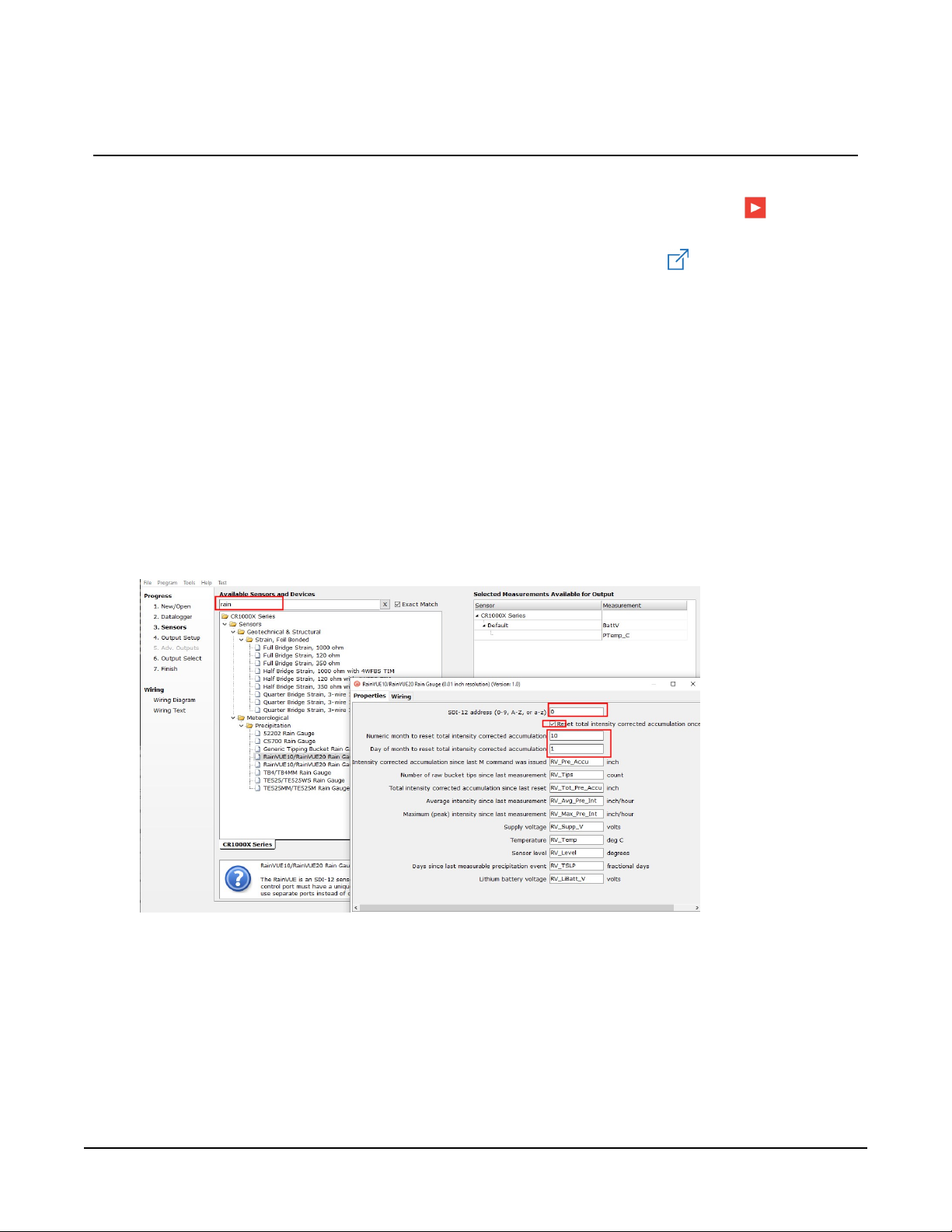
3. In the Available Sensors and Devices box, type RainVUE or find the sensor in the Sensors >
Meteorological > Precipitation folder, and double-click RainVUE10/RainVUE20 Rain
Gauge. Enter the correct SDI-12 Address for the sensor if it has been changed from the
factory-set default value. Type the numeric month and day for resetting the total
accumulation if you want to do this. Otherwise, uncheck the Reset total intensity corrected
accumulation once a year box.
RainVUE-Series SDI-12 Precipitation Sensors 2
Page 6
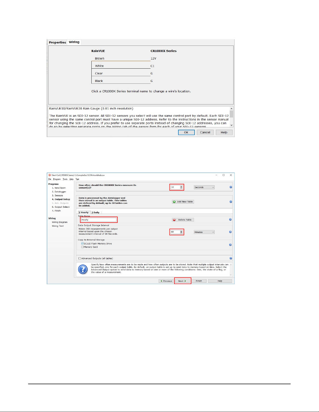
4. Click the Wiring tab. Click OK after wiring the sensor.
5. Repeat steps three and four for other sensors you want to measure. Click Next.
6. In Output Setup, type the scan rate, a Table Name, and Data Output Storage Interval. Click
Next.
RainVUE-Series SDI-12 Precipitation Sensors 3
Page 7
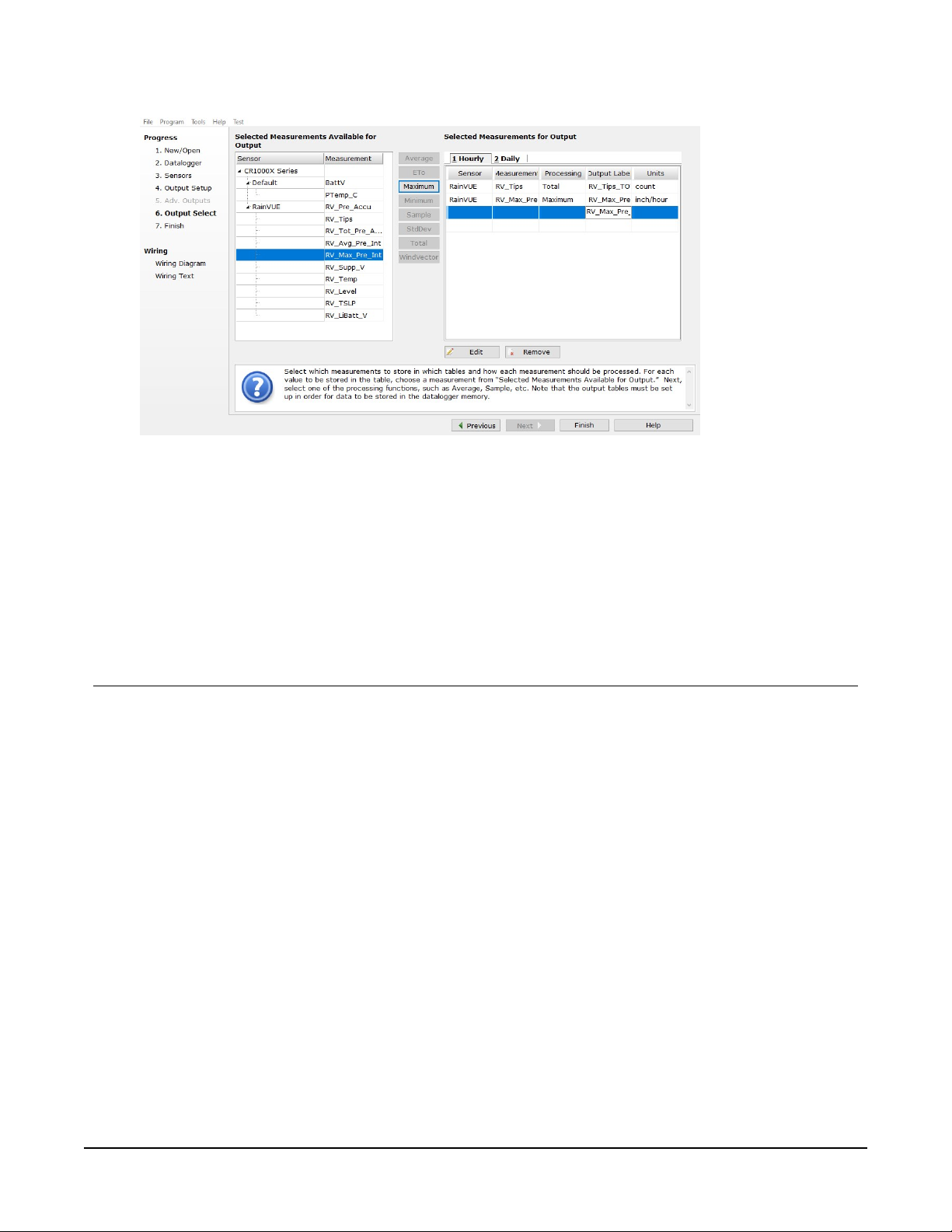
7. Select the output options.
8. Click Finish and save the program. Send the program to the data logger if the data logger
is connected to the computer.
9. If the sensor is connected to the data logger, check the output of the sensor in the data
display in LoggerNet, RTDAQ, or PC400 to make sure it is making reasonable
measurements.
5. Overview
The RainVUE-series funnels rainfall through a stainless-steel screen that traps debris, preventing
it from impeding the flow of precipitation. Rainfall flows through a nozzle into one of two bucket
halves. The internal tipping mechanism assembly rotates around a pivot point. The tipping
mechanism tips when the first bucket fills to a fixed calibrated level, then the tipping mechanism
moves the second bucket under the funnel. A magnet attached to the tipping mechanism
actuates a reed switch as the bucket tips. The outgoing water drains through outlets.
The aerodynamic design of the RainVUE-series reduces the amount of rain that wind carries away
from the collecting vessel. With traditional cylindrical tipping bucket rain sensors, wind can
reduce the rainfall catch by up to 20%. The RainVUE-series also includes a microprocessor that
corrects for rainfall intensity and outputs an SDI-12 signal. Refer to Rainfall intensity correction (p.
19) for more information.
RainVUE-Series SDI-12 Precipitation Sensors 4
Page 8

Features:
l Suitable for nonfreezing precipitation and high intensity rain events
l Digital processing to correct for high-intensity precipitation errors (see Specifications (p. 5))
l Unique aerodynamic shape increases measurement accuracy in windy conditions
l Meets WMO recommendations for accuracy and funnel area
l Adjustable mounting feet to simplify leveling
l Tilt, internal temperature, and voltage measurement for remote diagnostics on the sensor
l Compatible CRBasic data loggers: GRANITE-series, CR6, CR3000, CR1000X, CR800-series,
CR300-series, and CR1000
6. Specifications
Sensor type:
Rainfall per tip:
Output:
Response time:
Tipping bucket with magnetic reed switch
0.01 in (0.254 mm) or 0.1 mm (0.004 in)
SDI-12 version 1.4
0 s for
M0!
command and 1 s for
M1!
command
Accuracy
Rainfall: ±1% at 0 to 500 mm/h (0 to 20 in/hr) intensity
NOTE:
Accuracy over the rain intensity range requires a mechanical
calibration that is within 1% at a 1 in/h intensity. RainVUE-series
sensors are calibrated at the factory to meet this specification but
should be verified prior to deployment.
Tilt:
Temperature:
Supply voltage:
±1 °
±0.25 °C (±0.45 °F)
±0.5 V
Operating temperature:
Funnel diameter:
Height:
Power:
1 to 70 °C (34 to 158 °F)
20.0 cm (7.87 in)
43.5 to 46.5 cm (17.1 to 18.3 in) with feet adjustment
6 to 18 VDC
RainVUE-Series SDI-12 Precipitation Sensors 5
Page 9
Compliance documents: View at:
www.campbellsci.com/rainvue10
www.campbellsci.com/rainvue20
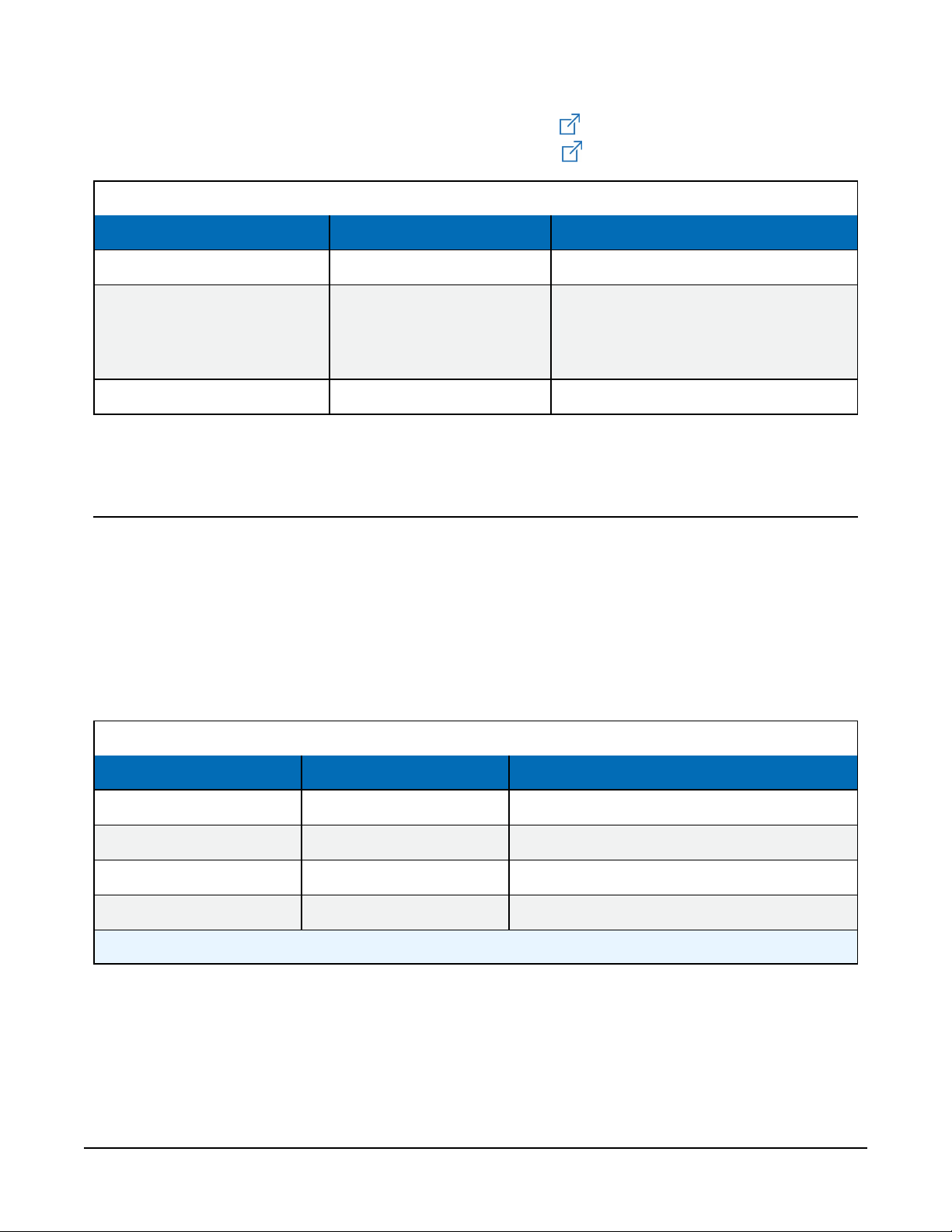
Table 6-1: RainVUE-series comparison
Specification RainVUE 10 RainVUE 20
Maximum rainfall intensity 1000 mm/h (39.4 in/h) 1500 mm/h (60 in/h)
Main collector body: 2-mm thick,
Material White, ASA LI-911 plastic
Weight 2 kg (4.5 lb) 6 kg (13 lb)
powder-coated aluminum
Base: LM6 marine-grade aluminum
7. Installation
If you are programming your data logger with Short Cut, skip Wiring (p. 6), and Data logger
programming (p. 7). Short Cut does this work for you. See QuickStart (p. 2), for a Short Cut
tutorial.
7.1 Wiring
Connect the wires in the order shown in the following table.
Table 7-1: Wire color, function, and data logger connection
Wire color Wire function Data logger connection
White SDI-12 signal C, SDI-12, or U configured for SDI-12
Clear Shield ⏚ (analog ground)
Brown Power 12V
Black Power ground G
1
U and C terminals are automatically configured by the measurement instruction.
If multiple SDI-12 sensors are connected to a data logger, Campbell Scientific recommends using
separate terminals when possible. However, multiple SDI-12 sensors can connect to the same
data logger control or U terminal. Each must have a unique SDI-12 address. Valid addresses are 0
through 9, a through z, and A through Z.
1
RainVUE-Series SDI-12 Precipitation Sensors 6
Page 10

For the CR6 and CR1000X data loggers, triggering conflicts may occur when a companion
terminal is used for a triggering instruction such as TimerInput(), PulseCount(), or
WaitDigTrig(). For example, if the RainVUE-series is connected to C3 on a CR1000X, C4
cannot be used in the TimerInput(), PulseCount(), or WaitDigTrig() instructions.
7.2 Data logger programming
Short Cut is the best source for up-to-date programming code for Campbell Scientific data
loggers. If your data acquisition requirements are simple, you can probably create and maintain a
data logger program exclusively with Short Cut. If your data acquisition needs are more complex,
the files that Short Cut creates are a great source for programming code to start a new program
or add to an existing custom program.
NOTE:
Short Cut cannot edit programs after they are imported and edited in CRBasic Editor.
A Short Cut tutorial is available in QuickStart (p. 2). If you wish to import Short Cut code into
CRBasic Editor to create or add to a customized program, follow the procedure in Importing
Short Cut code into CRBasic Editor (p. 29). Programming basics for CRBasic data loggers are
provided in the following sections. Downloadable example program is available at
www.campbellsci.com/downloads/rainvue-example-program .
7.2.1 SDI-12 programming
The SDI12Recorder() instruction is used to measure a RainVUE-series. This instruction sends
a request to the sensor to make a measurement and then retrieves the measurement from the
sensor. See SDI-12 measurements (p. 13) for more information.
For most data loggers, the SDI12Recorder() instruction has the following syntax:
SDI12Recorder(Destination, SDIPort, SDIAddress, “SDICommand”, Multiplier,
Offset, FillNAN, WaitonTimeout)
For the SDIAddress, alphabetical characters need to be enclosed in quotes (for example,
“A”). Also enclose the SDICommand in quotes as shown. The Destination parameter must
be an array. The required number of values in the array depends on the command (see Table 8-1
(p. 14)).
FillNAN and WaitonTimeout are optional parameters (refer to CRBasic Help for more
information).
RainVUE-Series SDI-12 Precipitation Sensors 7
Page 11
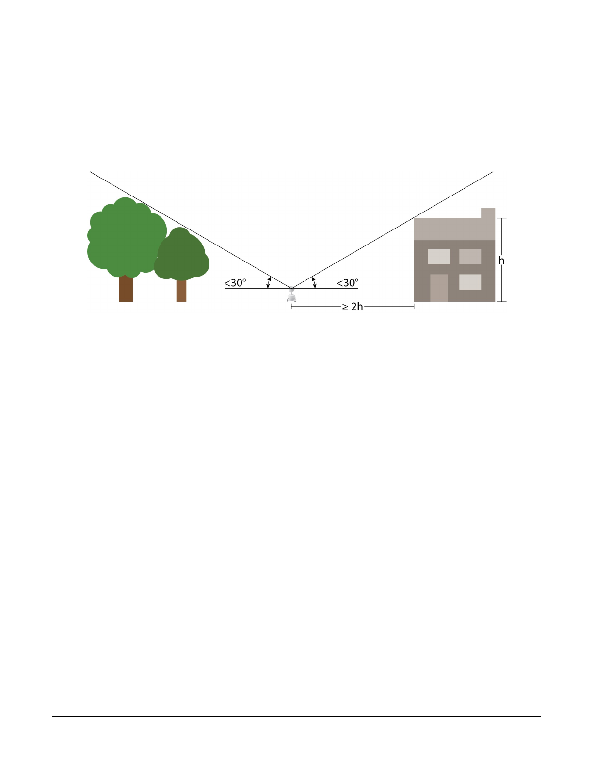
7.3 Siting
Mount the RainVUE-series in a relatively level location representative of the surrounding area.
Ensure that the funnel is horizontal. Place the sensor away from objects that obstruct the wind.
The distance should be at least 2 times the height of the obstruction. A concrete pad is
recommended, but the RainVUE-series should not be installed over a large paved or concrete
surface.
7.4 Mounting
The RainVUE-series has three equally-spaced leveling feet. Next to each leveling foot is a hole for
securing the sensor to a flat surface. The CM241 mounting bracket offered by Campbell Scientific
allows the RainVUE-series to be mounted on a CM300-series mounting pole or to a usersupplied 1.5 in. IPS (1.9 in. OD) unthreaded pipe.
Mounting poles are placed directly into a concrete foundation, attached to a concrete
foundation with the J-bolts, or are self-supporting with three legs (see FIGURE 7-1 (p. 9)).
RainVUE-Series SDI-12 Precipitation Sensors 8
Page 12
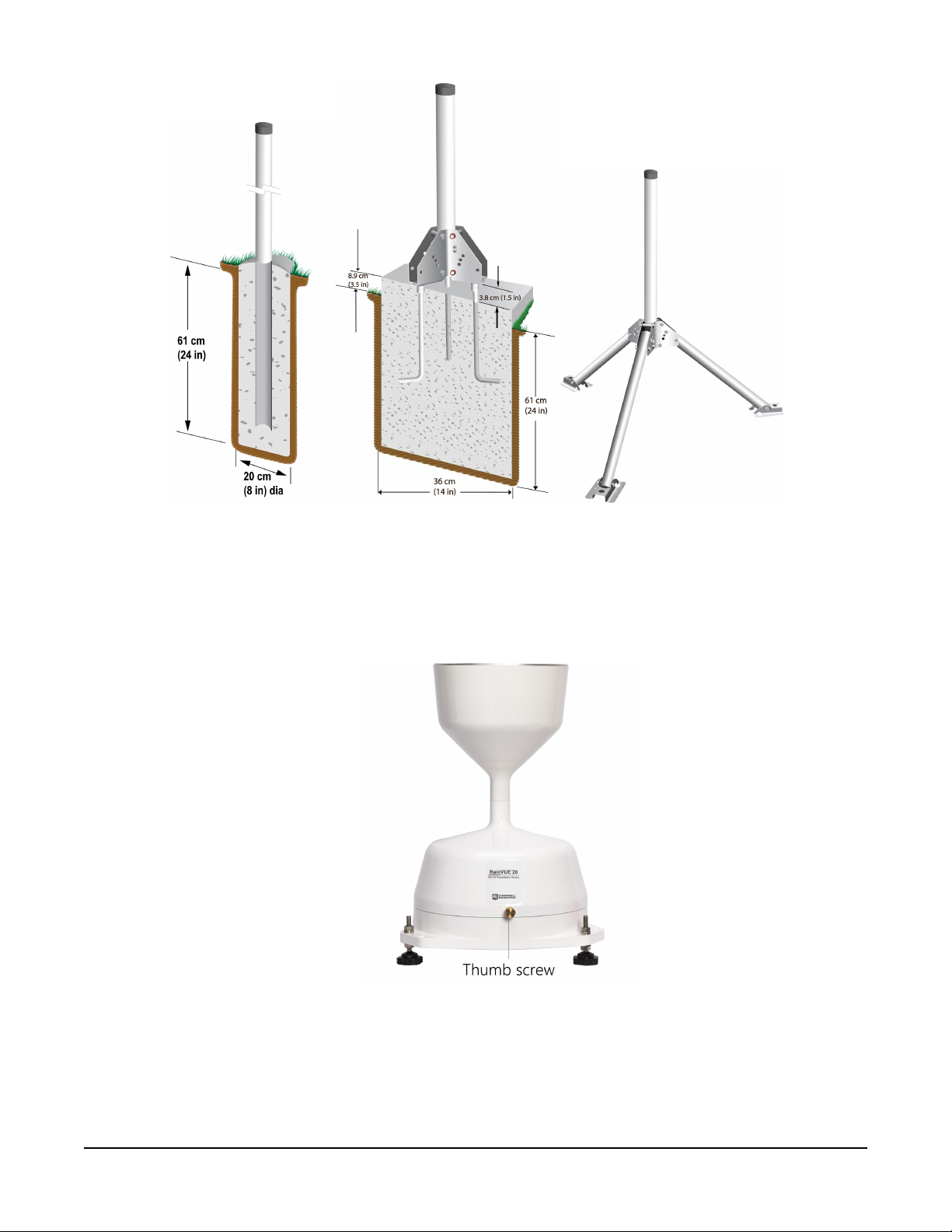
FIGURE 7-1. CM300-series mounting options
Procedure for mounting to a CM241 bracket and leveling the sensor:
1. Loosen and remove the three base thumb screws then lift the funnel upward.
FIGURE 7-2. Thumbscrew on RainVUE 20
RainVUE-Series SDI-12 Precipitation Sensors 9
Page 13
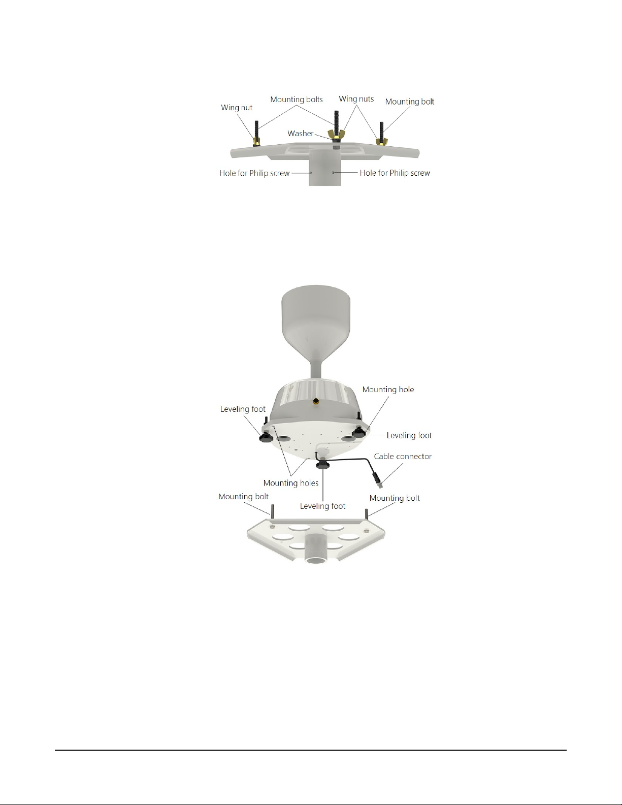
2. Remove the wing nuts and washers from the CM241 mounting bracket.
FIGURE 7-3. CM241 mounting bracket
3. Line up the RainVUE-series mounting holes over the CM241 mounting bolts and place the
sensor on the bracket.
FIGURE 7-4. Exploded view of RainVUE-series and CM241 bracket.
Wing nuts and pole not shown.
4. Loosely secure the RainVUE-series to the CM241 using the washers and wing nuts.
5. Place the CM241 on the pole or pipe and secure it to the pole or pipe by tightening the
screws with a Philips screwdriver (see FIGURE 7-3 (p. 10) and FIGURE 7-7 (p. 12)).
RainVUE-Series SDI-12 Precipitation Sensors 10
Page 14
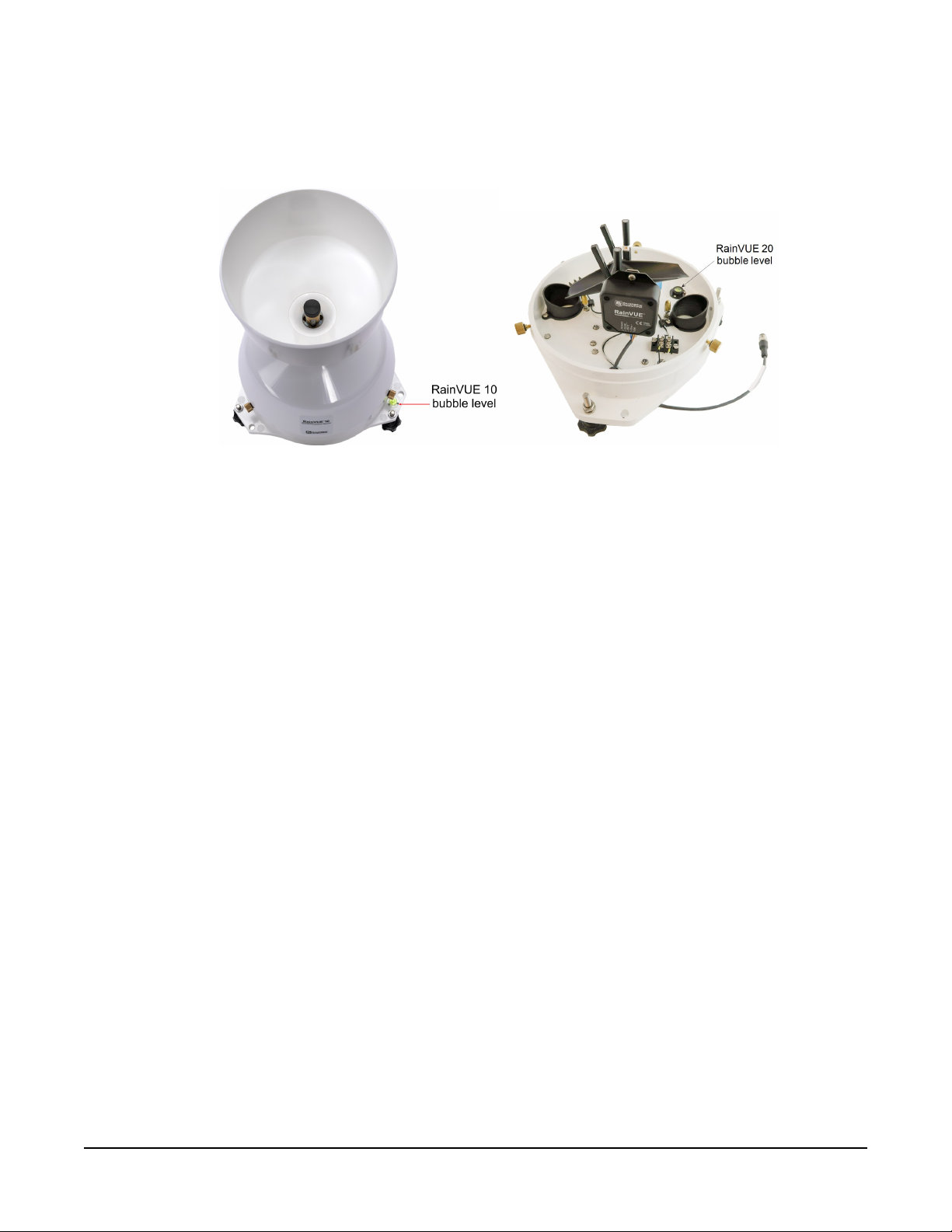
6. Adjust the three leveling feet on the RainVUE-series to level the RainVUE-series. The
RainVUE 10 has a bubble level next to a leveling foot. On the RainVUE 20, the funnel needs
to be removed to view the bubble level. See FIGURE 7-5 (p. 11).
FIGURE 7-5. Bubble levels on the RainVUE-series
7. Once level, tighten the wing nuts by hand until hand-tight and recheck the level.
8. Remove the piece of foam from under the tipping mechanism. This foam may be saved and
used whenever the sensor is transported.
9. Tip the tipping assembly several times to ensure the tipping mechanism is moving freely.
RainVUE-Series SDI-12 Precipitation Sensors 11
Page 15
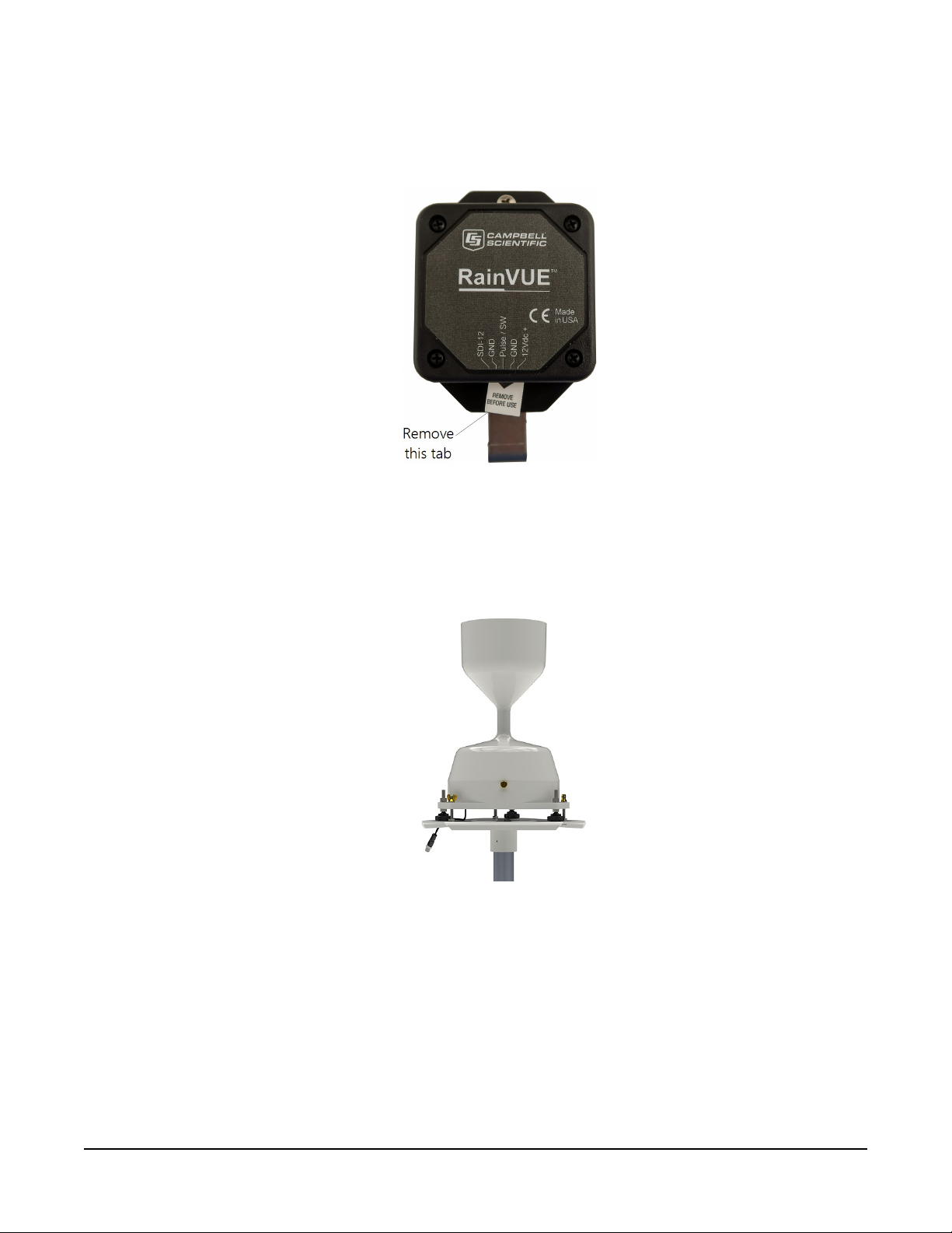
10. Pull and remove the insulator tab used to prevent draining of the backup coin cell battery
during shipping and storage. The tab extends from the bottom of the RainVUE-series
interface inside the RainVUE-series.
FIGURE 7-6. RainVUE-series interface and insulator tab
11. Replace the funnel and tighten the three base thumb screws to secure the funnel to the
base.
FIGURE 7-7. RainVUE-series mounted on a pole
12. Mate the extension cable connector to the cable connector. Only hand tighten the
connectors.
RainVUE-Series SDI-12 Precipitation Sensors 12
Page 16

8. Operation
This section discusses the following:
8.1 SDI-12 measurements 13
8.2 SDI-12 extended commands 15
8.3 SDI-12 version 1.4 identify measurement commands and responses 17
8.4 Rainfall intensity correction 19
8.5 Device Configuration Utility 19
8.1 SDI-12 measurements
The RainVUE-series responds to the SDI-12 measurement commands shown in Table 8-1 (p. 14).
When the data logger issues an M! command, the sensor should respond immediately indicating
how long it will take to perform the measurement. The data logger then waits that amount of
time or if the sensor finishes sooner, it will send a service request to the data logger indicating
data can be collected. After receiving the service request or waiting the indicated time, the data
logger will send the D! command to collect the data.
The C! command follows the same pattern as an M! command with the exception that it does
not require the data logger to pause its operation until the values are ready. Rather, the data
logger retrieves the data with the D! command on the next scan through the program. Another
measurement request is then sent so that data are ready on the next scan.
NOTE:
SDI-12 sensor support (p. 32) describes the SDI-12 commands. Additional SDI-12 information
is available at www.sdi-12.org .
RainVUE-Series SDI-12 Precipitation Sensors 13
Page 17

Table 8-1: SDI-12 measurement commands
SDI-12 command
aM!, aMC!,
aC!, aCC!,
aR0!, aRC0!
1
Values returned Units Comments
1. Intensity corrected
accumulation since last M, MC,
C, CC, R0, or RC0 command
was issued.
2. Number of raw bucket tips
since last measurement
3. Total intensity corrected
accumulation since reset
4. Average precipitation intensity
since last measurement
5. Maximum (peak) intensity
since last measurement
1. Supply voltage
2. Temperature
1. mm or inch
2. Counts
3. mm or inch
4. mm/hr or in/hr
5. mm/hr or in/hr
1. VDC
2. °C
Command
resets
accumulators
aM1!
aMC1!, aC1!,
aCC1!, aRC1!
3. Sensor level
4. Time since last measurable
precipitation event
5. Lithium battery voltage
1. Supply voltage
2. Temperature
3. Sensor level
4. Time since last measurable
precipitation event
5. Lithium battery voltage
3. Degrees from
normal, flat
4. Days
5. VDC
1. VDC
2. °C
Command
3. Degrees from
resets
normal, flat
accumulators
4. Days
5. VDC
RainVUE-Series SDI-12 Precipitation Sensors 14
Page 18

Table 8-1: SDI-12 measurement commands
SDI-12 command
aR9!
aI!
1
1. Intensity corrected
2. Number of raw bucket tips
3. Total intensity corrected
4. Average precipitation intensity
5. Maximum (peak) intensity
014CampbellMMMM100SN=xxxxxx
Where,
MMMM = RV20IN, RV20MM,
RV10IN, or RV10MM
Values returned Units Comments
accumulation since last M
command was issued
since last measurement
accumulation since reset
since last measurement
since last measurement
1. mm or inch
2. Counts
3. mm or inch
4. mm/hr or in/hr
5. mm/hr or in/hr
not applicable (NA)
Command
does not reset
accumulators
xxxxxx = serial number
1. Hardware Revision starting at 1
2. Reset Code
aV!
1
a is the sensor address.
2 = Power On
11=OS Update
12=Watchdog Timeout
NA
8.2 SDI-12 extended commands
Enter the following SDI-12 extended commands using the transparent mode while the computer
is communicating with the data logger through a terminal emulator program. It is accessed
through Campbell Scientific data logger support software or other terminal emulator programs.
Data logger keyboards and displays cannot be used. Refer to SDI-12 transparent mode (p. 38) for
more information.
RainVUE-Series SDI-12 Precipitation Sensors 15
Page 19

Table 8-2: SDI-12 extended commands
SDI-12
command
1
aXRDT! Read sensor date and time.
aXWDT+MM/DD/YYYY
hh:mm:ss!
aXWARA!
aXWA+xx.xx!
Where xx.xx = current rain
value
Values returned or function Comments
Write date and time.
Typically this command is
The extended write adjusted rainfall
issued on the start of the
accumulator command. Resets the
water year, which is
total adjusted rain accumulator to
normally October 1 or
0.00.
January 1.
Resets the total adjusted rain to a
current value and returns the number
of values.
Used when replacing the
RainVUE-series midway
Follow this command with the aD0!
through a water year.
command to get the new adjusted
rain.
aXWRESET! Resets all accumulators
Resets RTC or 24 hour tick counter to
aXWD!
midnight.
Zero tilt sensor (XWTILT) status.
Returns a status flag indicating the
aXWTILT!
success of the leveling process.
s = 0 Success
s = 1 Error (cannot zero the sensor)
Reads the tilt angle (degrees) of
aXRTILT!
the tilt sensor.
This command is a simple
way for data loggers to sync
the time clock without
having to format the SDI-12
command.
Mechanically balance the
sensor, then issue this
command.
When this command is
issued right after the sensor
is zeroed, it should return
0.00 degrees. This
command verifies the
RainVUE-series is level.
RainVUE-Series SDI-12 Precipitation Sensors 16
Page 20
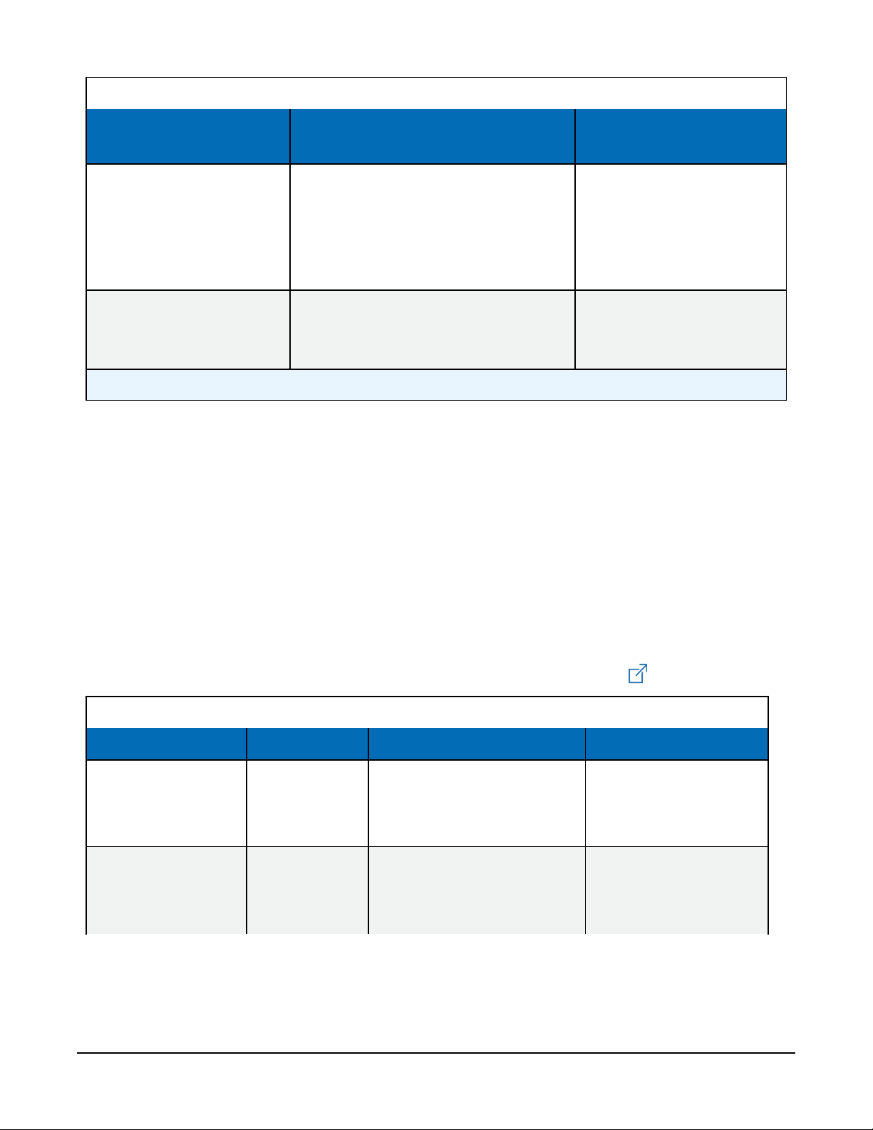
Table 8-2: SDI-12 extended commands
SDI-12
command
aXTEST!
aXHELP!
1
a is the sensor address.
1
Values returned or function Comments
Returns two lines of header
information, then returns updated
data at every tip and every 2 seconds
or until a break is detected with each
line terminated with a <CR><LF>.
Lists the standard measurement and
extended commands supported by the
RainVUE-series.
Command is only intended
for testing and debugging
the sensor.
Command is only intended
for testing and debugging
the sensor.
8.3 SDI-12 version 1.4 identify measurement commands and responses
Version 1.4 compliant sensors must respond to identify commands for each type of measurement
command and each parameter with a command. The broad identify commands return how many
variables will be returned with a given measurement command and the time it will take the
sensor to respond. The specific identify parameter commands will return a SHEF code, the
measurement units, and the type of measurement (sample, count, or average). For more
information see the SDI-12 version 1.4 specification.
(http://sdi-12.org/current_specification/SDI-12_version-1_4-Jan-10-2019.pdf )
Table 8-3: Identify commands for the RainVUE-series
Type of command Command Sensor response Comment
Identify
measurement for
M commands
Identify
measurement for
C commands
aIM!, aIMC!,
aM1!, aIMC1!
aIC!, aICC!,
aIC1!,
aICC1!
atttn
atttnn
RainVUE-Series SDI-12 Precipitation Sensors 17
ttt: response time
(seconds)
n: # of values returned
ttt: response time
(seconds)
nn: # of values returned
Page 21

Table 8-3: Identify commands for the RainVUE-series
Type of command Command Sensor response Comment
Identify
measurement for the
V command
Identify
measurement for
parameter 1 of
M command
Identify
measurement for
parameter 2 of
M command
Identify
measurement for
parameter 3 of
M command
aIV!
aIM_001!
aIM_002!
aIM_003!
atttn
aAdjRain,Inches
or aAdjRain,mm
aRawTips,Tips
aTotAdjRain,Inches
or aTotAdjRain,mm
ttt: response time
(seconds)
n: # of values returned
AdjRain: adjusted or
intensity-corrected
precipitation since last
measurement
Units: inches or mm
RawTips: number of raw
bucket tips since last
measurement (counts)
Units: counts
TotAdjRain: total
adjusted or total
intensity corrected
precipitation since last
reset
Identify
measurement for
parameter 4 of
M command
Identify
measurement for
parameter 5 of
M command
aIM_004!
aIM_005!
aAvgInt,Inches/Hour
or aAvgInt,mm/Hour
aMaxInt,Inches/Hour
or aMaxInt,mm/Hour
Units: inches or mm
AvgInt: average
precipitation intensity
since last measurement
Units: inches/hour or
mm/hour
MaxInt: maximum peak
precipitation intensity
since last measurement
Units: inches/hour or
mm/hour
RainVUE-Series SDI-12 Precipitation Sensors 18
Page 22

8.4 Rainfall intensity correction
During intense rainfall, extra water can accumulate in the bucket before the tipping mechanism
tips. The following graph shows the relationship between bucket volume and rainfall rate. The
RainVUE-series includes a microprocessor that corrects for the intensity sensitivity of the bucket
mechanism. This correction adjusts the rainfall rate based on the time between bucket tips. An
electronic timer precisely measures the time between tips.
8.5 Device Configuration Utility
Use Device Configuration Utility to change the SDI-12 address, view sensor measurements, collect
data, and update an operating system (see Updating operating system (p. 26)).
RainVUE-Series SDI-12 Precipitation Sensors 19
Page 23

1. Loosen and remove the three base thumb screws then lift the funnel upward.
2. Use a Philips screwdriver to remove the four screws on the RainVUE-series interface.
3. Remove the interface cover to access the USB port.
4. Open Device Configuration Utility.
RainVUE-Series SDI-12 Precipitation Sensors 20
Page 24

5. Type RainVUE-series in the Device Type box and click RainVUE-series.
6. If this is the first time connecting the RainVUE-series to the computer, click install USB
driver for the RainVUE before connecting the cable to the computer.
7. Use the supplied USB cable to connect the RainVUE-series USB port to a computer USB
port.
8. Select the Communication Port in the left panel. RAINVUE will appear in the selection
dialog.
NOTE:
It may take a few seconds for the Communication Port to become available for use after
physically connecting the RainVUE-series to the computer.
9. Click Connect.
RainVUE-Series SDI-12 Precipitation Sensors 21
Page 25

10. To change the SDI-12 address, click the SDI-12 Address box and select a different value.
11. Click the Status tab to view tip counts, accumulation, and intensity information.
12. Click the Clock Control tab to change the Reference Clock Setting. Click Set Clock to
manually initiate a clock check of the reference time and station time.
RainVUE-Series SDI-12 Precipitation Sensors 22
Page 26

13. Click the Data Monitor tab to view real-time data. From the list, select the table you want
to display.
14. Click the Data Collection tab to manually collect data. Check the Destination Directory and
File Format to make sure the files are where you want them and in the right format. Select
the Collect Mode, tables, then click Start.
RainVUE-Series SDI-12 Precipitation Sensors 23
Page 27

The following shows data collected from an hourly rain table.
9. Maintenance and troubleshooting
NOTE:
All factory repairs and recalibrations require a returned material authorization (RMA) and
completion of the “Statement of Product Cleanliness and Decontamination” form. Refer to
the Assistance page at the end of this manual for more information.
This section discusses the following:
9.1 Maintenance 25
9.2 Troubleshooting 27
RainVUE-Series SDI-12 Precipitation Sensors 24
Page 28

9.1 Maintenance
To ensure reliable and accurate measurements, Campbell Scientific recommends doing the
following every month.
1. Check the integrity of the cable and data logger connections. Replace cable if damaged.
2. Inspect the funnel for any damage or blockage. To clear a blockage, remove the funnel
from the base and remove debris.
3. Clean the filter using the following procedure:
a. Unscrew the end cap from the filter tube
b. Carefully, remove the stainless-steel screen
c. Gently clean the filter
d. Place the filter on the filter tube and screw on the end cap
4. Level the RainVUE-series if necessary (see aXWTILT! and aXRTILT! command in Table
8-2 (p. 16)). The RainVUE 10 has a bubble level next to a leveling foot. On the RainVUE 20,
the funnel needs to be removed to view the bubble level.
5. Clean dirt from the tipping bucket. Avoid tipping the bucket if the RainVUE-series is still
connected to the data logger.
6. If the data logger is disconnected, check the tipping mechanism for stiffness.
a. Try to balance the bucket in its center position. It should be extremely difficult or
impossible to balance.
b. If the bucket balances easily, closely examine the tipping bucket assembly for dirt or
wear on the pivot pin and bucket tubs.
9.1.1 Internal lithium battery
An internal lithium coin cell battery powers the RainVUE-series during power loss of the main
12V power source. The battery allows the RainVUE-series to capture rain events for 12 to 15 days
depending on battery age, temperature, and frequency of rain detections and SDI-12
measurement request.
The M1! and IM1_005! SDI-12 commands report the lithium battery voltage (see Table 8-1 (p.
14) and Table 8-3 (p. 17)). Replace the battery when voltage is approximately 2.7VDC.
Campbell Scientific recommends replacing the battery every 2 to 3 years and after each loss of
power event. High temperature can reduce the battery life and low temperatures can decrease
battery capacity lowering available power and sensor runtime.
RainVUE-Series SDI-12 Precipitation Sensors 25
Page 29

Remove the backup battery when the sensor is removed from service. Replace the battery when
the RainVUE-series is placed back in service.
Battery replacement procedure:
1. Loosen and remove the three base thumb screws then lift the funnel upward.
2. Use a Philips screwdriver to remove the four screws on the RainVUE-series interface.
3. Remove the interface cover.
4. Replace the old lithium battery with the new battery (3 V Coin Cell CR2032).
5. Place the interface cover on the interface and secure with the four screws.
6. Replace the funnel and tighten the three base thumb screws to secure the funnel to the
base.
9.1.2 Updating operating system
1.
Go to www.campbellsci.com/downloads/rainvue-os , click Download Now, and click
Save File. This will download an .exe file on your computer.
RainVUE-Series SDI-12 Precipitation Sensors 26
Page 30

2. Double-click the .exe file. This will save the operating system file in
C:/Campbellsci/Lib/OperatingSystems.
3. Access Device Configuration Utility (see Device Configuration Utility (p. 19)).
4. Click the Send OS tab.
5. Click Start
6. Select the file. It will have an .a43 extension.
7. Click OK.
9.2 Troubleshooting
Symptom:
On a CRBasic data logger, data values report NAN, or on a non-Campbell Scientific data logger,
data values do not change when the tipping mechanism is activated and new measurement
commands are issued.
Solution:
1. Verify the RainVUE-series is wired correctly (Table 7-1 (p. 6)).
NOTE:
Connect the power wire to the data logger 12V terminal and not the SW12 terminal.
2. Verify the power to the RainVUE-series is in the appropriate range (6 to 18 VDC).
RainVUE-Series SDI-12 Precipitation Sensors 27
Page 31

3. Verify the correct SDI-12 address is being used when communicating with the RainVUEseries. Use the transparent mode to verify the data logger can communicate with the it. For
additional information, refer to SDI-12 transparent mode (p. 38).
Symptom:
Reported data values are lower than expected.
Solution:
1. Ensure that the filter is clean and allows water to flow through it.
2. Check that the tipping mechanism can move freely.
3. Use a voltmeter on the switch to verify the switch is activated as expected while
transitioning from one side to the other. While the tipping mechanism is in its resting
positions, the volt meter should read 3 to 5 V. When at the mid- point as it transitions from
one side to the other side, the volt meter should read 0 V.
4. Ensure that the RainVUE-series is level. The RainVUE 10 has a bubble level next to a
leveling foot. On the RainVUE 20, the funnel needs to be removed to view the bubble level.
5. Check the wires and connections between the switch and the interface are secure.
6. Verify no obstacles are preventing rain from entering the funnel.
Symptom:
Reported data values are higher than expected.
Solution:
1. Verify the tipping mechanism is not stuck near the center of its movement from one side to
the other.
2. Verify that the wires and connections between the switch and the interface are secure.
3. Verify that the RainVUE-series is not under a structure that will drip into the it.
For more information refer to:
www.campbellsci.com/videos/sdi12-sensors-transparent-mode
www.campbellsci.com/videos/sdi12-sensors-watch-or-sniffer-mode
RainVUE-Series SDI-12 Precipitation Sensors 28
Page 32

Appendix A. Importing Short
Cut code into CRBasic Editor
Short Cut creates a .DEF file that contains wiring information and a program file that can be
imported into the CRBasic Editor. By default, these files reside in the C:\campbellsci\SCWin
folder.
Import Short Cut program file and wiring information into CRBasic Editor:
1. Create the Short Cut program. After saving the Short Cut program, click the Advanced tab
then the CRBasic Editor button. A program file with a generic name will open in CRBasic.
Provide a meaningful name and save the CRBasic program. This program can now be
edited for additional refinement.
NOTE:
Once the file is edited with CRBasic Editor, Short Cut can no longer be used to edit the
program it created.
2. To add the Short Cut wiring information into the new CRBasic program, open the .DEF file
located in the C:\campbellsci\SCWin folder, and copy the wiring information, which is at
the beginning of the .DEF file.
3. Go into the CRBasic program and paste the wiring information into it.
4. In the CRBasic program, highlight the wiring information, right-click, and select Comment
Block. This adds an apostrophe (') to the beginning of each of the highlighted lines, which
instructs the data logger compiler to ignore those lines when compiling. The Comment
Block feature is demonstrated at about 5:10 in the CRBasic | Features video .
RainVUE-Series SDI-12 Precipitation Sensors 29
Page 33

Appendix B. XTEST! operation
Use the XTEST! SDI-12 command to validate the calibration. Enter this command in the
transparent mode while the computer is communicating with the data logger through a terminal
emulator program.
This command displays simulated rain fall data that does not affect rain accumulators used for
the normal operation. It runs for 60 minutes then returns to normal operation. The XTEST!
command can also be aborted by a break on the SDI-12 data line. Therefore, suspend the data
logger program before you begin field calibration.
To validate the calibration, first run a fixed amount of water through the RainVUE-series, then
use the XTEST! command and compare the results. A common amount of simulated rain is 946
ml which equates to 115 tips on the 0.01 inch rain gauge at a rate of 2 inches of rain per hour or
slower.
Initially, the command sends the following header information.
Raw
Tip
For each second or each tip detected, the command displays a new line of data, such as the
following.
Raw
Tip
0 0.000 0.000 0
0 0.000 0.000 0
Eventually, the numbers should start changing and the latest data should give an indication of
how close the gauge is to calibration.
Corrected
Rain Fall
Corrected
Rain Fall
Total
Rain Fall Balance
Total
Rain Fall Balance
RainVUE-Series SDI-12 Precipitation Sensors 30
Page 34

Raw
Tip
0 0.000 0.000 0
0 0.000 0.000 0
1 0.010 0.010 33
2 0.011 0.021 68
3 0.011 0.032 51
4 0.012 0.044 50
5 0.010 0.054 51
6 0.011 0.065 49
8 0.023 0.088 51
|
|
110 0.011 1.180 51
Corrected
Rain Fall
Total
Rain Fall Balance
111 0.011 1.191 50
112 0.011 1.202 51
113 0.012 1.214 51
114 0.010 1.224 51
114 0.000 1.224 51
114 0.000 1.224 51
The corrected rain fall and total rain fall values include intensity correction. When the simulated
rain is ran through the gauge at a fast rate, the number of tips may be lower than expected, but
the corrected rain fall should be close to the actual amount of simulated rain.
The balance value represents how balanced the tipping mechanism is as it tips from one side to
the other. If the gauge needs to be adjusted, it is best to try to keep the balance as close to 50%
as possible. The balance value is only valid if the simulated rain is being applied at a constant
rate. It is best to look at this value after the test has been running for consistently for a few tips.
RainVUE-Series SDI-12 Precipitation Sensors 31
Page 35

Appendix C. SDI-12 sensor support
SDI-12, Serial Data Interface at 1200 baud, is a protocol developed to simplify sensor and data
logger compatibility. Only three wires are necessary — serial data, ground, and 12 V. With unique
addresses, multiple SDI-12 sensors can connect to a single SDI-12 terminal on a Campbell
Scientific data logger.
This appendix discusses the structure of SDI-12 commands and the process of querying SDI-12
sensors. For more detailed information, refer to version 1.4 of the SDI-12 protocol, available at
www.sdi-12.org .
For additional information, refer to the SDI-12 Sensors | Transparent Mode and SDI-12 Sensors |
Watch or Sniffer Mode videos.
C.1 SDI-12 command basics
SDI-12 commands have three components:
l Sensor address (a) – a single character and the first character of the command. Use the
default address of zero (0) unless multiple sensors are connected to the same port.
l Command body – an upper case letter (the “command”), optionally followed by one or
more alphanumeric qualifiers.
l Command termination (!) – an exclamation mark.
An active sensor responds to each command. Responses have several standard forms and always
terminate with <CR><LF> (carriage return and line feed). Standard SDI-12 commands are listed
in Table C-1 (p. 32).
Table C-1: Campbell Scientific sensor SDI-12 command and response set
Name Command
Acknowledge Active
Send Identification
Start Verification
a!
aI!
aV!
Response
a<CR><LF>
allccccccccmmmmmmvvvxxx...xx
<CR><LF>
atttn <CR><LF>
1
RainVUE-Series SDI-12 Precipitation Sensors 32
Page 36

Table C-1: Campbell Scientific sensor SDI-12 command and response set
Name Command
Address Query
Change Address
Start Measurement
Start Measurement
and Request CRC
Start Concurrent Measurement
StartConcurrentMeasurement
and Request CRC
Send Data
Continuous Measurement
?!
aAb!
aM!
aM1!...aM9!
aMC!
aMC1!...aMC9!
aC!
aC1!...aC9!
aCC!
aCC1!...aCC9!
aD0!...aD9!
aR0!...aR9!
Response
a<CR><LF>
b<CR><LF>
atttn<CR><LF>
atttn <CR><LF>
atttnn<CR><LF>
atttnn<CR><LF>
a<values><CR><LF> or
a<values><CRC><CR><LF>
a<values><CR><LF>
1
Continuous Measurement
and Request CRC
Extended Commands
1
Information on each of these commands is given in the following sections.
aRC0!...aRC9!
aXNNN!
a<values><CRC><CR><LF>
a<values><CR><LF>
C.1.1 Acknowledge active command (a!)
The Acknowledge Active command (a!) is used to test a sensor on the SDI-12 bus. An active
sensor responds with its address.
C.1.2 Send identification command (al!)
Sensor identifiers are requested by issuing command aI!. The reply is defined by the sensor
manufacturer but usually includes the sensor address, SDI-12 version, manufacturer’s name, and
sensor model information. Serial number or other sensor specific information may also be
included.
aI!
a Sensor SDI-12 address
allccccccccmmmmmmvvvxxx...xx<CR><LF>
ll SDI-12 version number (indicates compatibility)
RainVUE-Series SDI-12 Precipitation Sensors 33
Page 37

cccccccc 8-character vendor identification
mmmmmm 6 characters specifying the sensor model
vvv 3 characters specifying the sensor version (operating system)
xxx…xx
<CR><LF>
Source: SDI-12: A Serial-Digital Interface Standard for Microprocessor-Based Sensors (see References).
Up to 13 optional characters used for a serial number or other specific
sensor information that is not relevant for operation of the data logger
Terminates the response
C.1.3 Start verification command (aV!)
The response to a Start Verification command can include hardware diagnostics, but like the aI!
command, the response is not standardized.
Command: aV!
Response: atttn<CR><LF>
a = sensor address
ttt = time, in seconds, until verification information is available
n = the number of values to be returned when one or more subsequent D! commands are issued
C.1.4 Address query command (?!)
Command ?! requests the address of the connected sensor. The sensor replies to the query with
the address, a. This command should only be used with one sensor on the SDI-12 bus at a time.
C.1.5 Change address command (aAb!)
Multiple SDI-12 sensors can connect to a single SDI-12 terminal on a data logger. Each device on
a single terminal must have a unique address.
A sensor address is changed with command aAb!, where a is the current address and b is the
new address. For example, to change an address from 0 to 2, the command is 0A2!. The sensor
responds with the new address b, which in this case is 2.
NOTE:
Only one sensor should be connected to a particular terminal at a time when changing
addresses.
RainVUE-Series SDI-12 Precipitation Sensors 34
Page 38

C.1.6 Start measurement commands (aM!)
A measurement is initiated with the M! command. The response to each command has the form
atttn<CR><LF>, where
a = sensor address
ttt = time, in seconds, until measurement data is available. When the data is ready, the sensor
notifies the data logger, and the data logger begins issuing D commands.
n = the number of values returned when one or more subsequent D commands are issued. For
the aM! command, n is an integer from 0 to 9.
When the aM! is issued, the data logger pauses its operation and waits until either it receives the
data from the sensor or the time, ttt, expires. Depending on the scan interval of the data logger
program and the response time of the sensor, this may cause skipped scans to occur. In this case
make sure your scan interval is longer than the longest measurement time (ttt).
Table C-2: Example aM! sequence
0M!
00352<CR><LF>
0<CR><LF>
0D0!
0+.859+3.54<CR><LF>
The data logger makes a request to sensor 0 to start a measurement.
Sensor 0 immediately indicates that it will return two values within
the next 35 seconds.
Within 35 seconds, sensor 0 indicates that it has completed the
measurement by sending a service request to the data logger.
The data logger immediately issues the first D command to collect
data from the sensor.
The sensor immediately responds with the sensor address and the two
values.
C.1.7 Start concurrent measurement commands (aC!)
A concurrent measurement (aC!) command follows the same pattern as the aM! command with
the exception that it does not require the data logger to pause its operation, and other SDI-12
sensors may take measurements at the same time. The sensor will not issue a service request to
notify the data logger that the measurement is complete. The data logger will issue the aD0!
command during the next scan after the measurement time reported by the sensor has expired.
To use this command, the scan interval should be 10 seconds or less. The response to each
command has the form atttn<CR><LF>, where
a = the sensor address
ttt = time, in seconds, until the measurement data is available
RainVUE-Series SDI-12 Precipitation Sensors 35
Page 39

nn = the number of values to be returned when one or more subsequent D commands are
issued.
See the following example. A data logger has three sensors wired into terminal C1. The sensors
are addresses X, Y, and Z. The data logger will issue the following commands and receive the
following responses:
Table C-3: Example aC! sequence
XC!
X03005<CR><LF>
YC!
Y04006<CR><LF>
ZC!
Z02010<CR><LF>
ZD0!
The data logger makes a request to sensor X to start
a concurrent measurement.
Sensor X immediately indicates that it will have 5
(05) values ready for collection within the next 30
(030) seconds.
The data logger makes a request to sensor Y to start
a concurrent measurement.
Sensor Y immediately indicates that it will have 6
(06) values ready for collection within the next 40
(040) seconds.
The data logger makes a request to sensor Z to start
a concurrent measurement.
Sensor Z immediately indicates that it will have 10
values ready for collection within the next 20 (020)
seconds.
After 20 seconds have passed, the data logger starts
the process of collecting the data by issuing the first
D command to sensor Z.
Z+1+2+3+4+5+6+7+8+9+10<CR><LF>
XD0!
X+1+2+3+4+5<CR><LF>
Sensor Z immediately responds with the sensor
address and the 10 values.
10 seconds later, after a total of 30 seconds have
passed, the data logger starts the process of
collecting data from sensor X by issuing the first D
command.
The sensor immediately responds with the sensor
address and the 5 values.
RainVUE-Series SDI-12 Precipitation Sensors 36
Page 40

Table C-3: Example aC! sequence
YD0!
Ten seconds later, after a total of 40 seconds have
passed, the data logger starts the process of
collecting data from sensor Y by issuing the first D
command.
Y+1+2+3+4+5+6<CR><LF>
The sensor immediately responds with the sensor
address and the 6 values.
C.1.8 Start measurement commands with cyclic redundancy check (aMC! and aCC!)
Error checking is done by using measurement commands with cyclic redundancy checks (aMC!
or aCC!). This is most commonly implemented when long cable lengths or electronic noise may
impact measurement transmission to the data logger. When these commands are used, the data
returned in response to D or R commands must have a cyclic redundancy check (CRC) code
appended to it. The CRC code is a 16-bit value encoded within 3 characters appended before the
<CR><LF>. This code is not returned in the data table but checked by the data logger as it
comes. The code returned is based on the SDI-12 protocol. See the SDI-12 communication
specification for version 1.3 available at www.sdi-12.org to learn more about how the CRC code is
developed.
C.1.9 Stopping a measurement command
A measurement command (M!) is stopped if it detects a break signal before the measurement is
complete. A break signal is sent by the data logger before most commands.
A concurrent measurement command (C!) is aborted when another valid command is sent to the
sensor before the measurement time has elapsed.
C.1.10 Send data command (aD0! … aD9!)
The Send Data command requests data from the sensor. It is issued automatically with every type
of measurement command (aM!, aMC!, aC!, aCC!). When the measurement command is aM!
or aMC!, the data logger issues the aD0! command once a service request has been received
from the sensor or the reported time has expired. When the data logger is issuing concurrent
commands (aC! or aCC!), the Send Data command is issued after the required time has elapsed
(no service request will be sent by the sensor). In transparent mode (see SDI-12 transparent mode
(p. 38) ), the user asserts this command to obtain data.
Depending on the type of data returned and the number of values a sensor returns, the data
logger may need to issue aD0! up to aD9! to retrieve all data. A sensor may return up to 35
RainVUE-Series SDI-12 Precipitation Sensors 37
Page 41

characters of data in response to a D command that follows an M! or MC! command. A sensor
may return up to 75 characters of data in response to a D command that follows a C! or CC!
command. Data values are separated by plus or minus signs.
Command: aD0! (aD1! … aD9!)
Response: a<values><CR><LF> or a<values><CRC><CR><LF>
where:
a = the sensor address
<values> = values returned with a polarity sign (+ or –)
<CR><LF> = terminates the response
<CRC> = 16-bit CRC code appended if data was requested with aMC! or aCC!.
C.1.11 Continuous measurement command (aR0! … aR9!)
Sensors that are able to continuously monitor the phenomena to be measured can be read
directly with the R commands (R0! … R9!). The response to the R commands mirrors the Send
Data command (aD0!). A maximum of 75 characters can be returned in the <values> part of the
response to the R command.
C.1.12 Extended commands
Many sensors support extended SDI-12 commands. An extended command is specific to a make
of sensor and tells the sensor to perform a specific task. They have the following structure.
Responses vary from unit to unit. See the sensor manual for specifics.
Command: aXNNNN!
The command will start with the sensor address (a), followed by an X, then a set of optional
letters, and terminate with an exclamation point.
Response: a<optional values><CR><LF>
The response will start with the sensor address and end with a carriage return/line feed.
C.2 SDI-12 transparent mode
System operators can manually interrogate and enter settings in probes using transparent mode.
Transparent mode is useful in troubleshooting SDI-12 systems because it allows direct
communication with probes. Data logger security may need to be unlocked before activating the
transparent mode.
RainVUE-Series SDI-12 Precipitation Sensors 38
Page 42

Transparent mode is entered while the computer is communicating with the data logger through
a terminal emulator program. It is accessed through Campbell Scientific data logger support
software or other terminal emulator programs. Data logger keyboards and displays cannot be
used.
The terminal emulator is accessed by navigating to the Tools list in PC400 or the Datalogger list
in the Connect screen of LoggerNet.
Watch the video: SDI-12 Sensors | Transparent Mode.
Data loggers from other manufacturers will also have a transparent mode. Refer to those manuals
on how to use their transparent mode.
The following examples show how to enter transparent mode and change the SDI-12 address of
an SDI-12 sensor. The steps shown in Changing an SDI-12 address (p. 39) are used with most
Campbell Scientific data loggers.
C.2.1 Changing an SDI-12 address
This example was done with a CR1000X, but the steps are only slightly different for CR6, CR3000,
CR800-series, CR300-series, CR1000 data loggers.
1. Connect an SDI-12 sensor to the CR1000X.
2. In LoggerNet Connect, under Datalogger, click Terminal Emulator. The terminal emulator
window opens.
3. Under Select Device, located in the lower left side of the window, select the CR1000X
4. Click Open Terminal.
5. Select All Caps Mode.
6. Press Enter until the data logger responds with the CR1000X> prompt.
RainVUE-Series SDI-12 Precipitation Sensors 39
Page 43

7. Type SDI12 and press Enter.
8. At the Select SDI12 Port prompt, type the number corresponding to the control port where
the sensor is connected and press Enter. The response Entering SDI12 Terminal indicates
that the sensor is ready to accept SDI-12 commands.
9. To query the sensor for its current SDI-12 address, type ?! and press Enter. The sensor
responds with its SDI-12 address. If no characters are typed within 60 seconds, the mode is
exited. In that case, simply type SDI12 again, press Enter, and type the correct control port
number when prompted.
10. To change the SDI-12 address, type aAb!, where a is the current address from the previous
step and b is the new address. Press Enter. The sensor changes its address and responds
with the new address. In the following example, the sensor address is changed from 0 to B.
11. To exit SDI-12 transparent mode, click Close Terminal.
RainVUE-Series SDI-12 Precipitation Sensors 40
Page 44

NOTE:
The transparent mode for the CR6, CR3000, CR800-series, CR300-series, and CR1000 data
loggers is similar to that shown for the CR1000X.
C.3 References
SDI-12 Support Group. SDI-12: A Serial-Digital Interface Standard for Microprocessor-Based
Sensors – Version 1.4. River Heights, UT: SDI-12 Support Group, 2017. http://www.sdi-
12.org/current_specification/SDI-12_version-1_4-Dec-1-2017.pdf.
RainVUE-Series SDI-12 Precipitation Sensors 41
Page 45

Limited warranty
Products manufactured by Campbell Scientific are warranted by Campbell Scientific to be free
from defects in materials and workmanship under normal use and service for twelve months from
the date of shipment unless otherwise specified on the corresponding product webpage. See
Product Details on the Ordering Information pages at www.campbellsci.com. Other
manufacturer's products, that are resold by Campbell Scientific, are warranted only to the limits
extended by the original manufacturer.
Refer to www.campbellsci.com/terms#warranty for more information.
CAMPBELL SCIENTIFIC EXPRESSLY DISCLAIMS AND EXCLUDES ANY IMPLIED WARRANTIES OF
MERCHANTABILITY OR FITNESS FOR A PARTICULAR PURPOSE. Campbell Scientific hereby
disclaims, to the fullest extent allowed by applicable law, any and all warranties and conditions
with respect to the Products, whether express, implied or statutory, other than those expressly
provided herein.
Page 46

Assistance
Products may not be returned without prior authorization.
Products shipped to Campbell Scientific require a Returned Materials Authorization (RMA) or
Repair Reference number and must be clean and uncontaminated by harmful substances, such as
hazardous materials, chemicals, insects, and pests. Please complete the required forms prior to
shipping equipment.
Campbell Scientific regional offices handle repairs for customers within their territories. Please
see the back page for the Global Sales and Support Network or visit
www.campbellsci.com/contact to determine which Campbell Scientific office serves your country.
To obtain a Returned Materials Authorization or Repair Reference number, contact your
CAMPBELL SCIENTIFIC regional office. Please write the issued number clearly on the outside of
the shipping container and ship as directed.
For all returns, the customer must provide a “Statement of Product Cleanliness and
Decontamination” or “Declaration of Hazardous Material and Decontamination” form and
comply with the requirements specified in it. The form is available from your CAMPBELL
SCIENTIFIC regional office. Campbell Scientific is unable to process any returns until we receive
this statement. If the statement is not received within three days of product receipt or is
incomplete, the product will be returned to the customer at the customer’s expense. Campbell
Scientific reserves the right to refuse service on products that were exposed to contaminants that
may cause health or safety concerns for our employees.
Page 47

Safety
DANGER — MANY HAZARDS ARE ASSOCIATED WITH INSTALLING, USING, MAINTAINING, AND WORKING ON OR AROUND TRIPODS, TOWERS,
AND ANY ATTACHMENTS TO TRIPODS AND TOWERS SUCH AS SENSORS, CROSSARMS, ENCLOSURES, ANTENNAS, ETC. FAILURE TO PROPERLY
AND COMPLETELY ASSEMBLE, INSTALL, OPERATE, USE, AND MAINTAIN TRIPODS, TOWERS, AND ATTACHMENTS, AND FAILURE TO HEED
WARNINGS, INCREASES THE RISK OF DEATH, ACCIDENT, SERIOUS INJURY, PROPERTY DAMAGE, AND PRODUCT FAILURE. TAKE ALL
REASONABLE PRECAUTIONS TO AVOID THESE HAZARDS. CHECK WITH YOUR ORGANIZATION'S SAFETY COORDINATOR (OR POLICY) FOR
PROCEDURES AND REQUIRED PROTECTIVE EQUIPMENT PRIOR TO PERFORMING ANY WORK.
Use tripods, towers, and attachments to tripods and towers only for purposes for which they are designed. Do not exceed design limits. Be
familiar and comply with all instructions provided in product manuals. Manuals are available at www.campbellsci.com. You are responsible for
conformance with governing codes and regulations, including safety regulations, and the integrity and location of structures or land to which
towers, tripods, and any attachments are attached. Installation sites should be evaluated and approved by a qualified engineer. If questions or
concerns arise regarding installation, use, or maintenance of tripods, towers, attachments, or electrical connections, consult with a licensed and
qualified engineer or electrician.
General
l Protect from over-voltage.
l Protect electrical equipment from water.
l Protect from electrostatic discharge (ESD).
l Protect from lightning.
l Prior to performing site or installation work, obtain required approvals and permits. Comply with all governing structure-height
regulations.
l Use only qualified personnel for installation, use, and maintenance of tripods and towers, and any attachments to tripods and towers.
The use of licensed and qualified contractors is highly recommended.
l Read all applicable instructions carefully and understand procedures thoroughly before beginning work.
l Wear a hardhat and eye protection, and take other appropriate safety precautions while working on or around tripods and towers.
l Do not climb tripods or towers at any time, and prohibit climbing by other persons. Take reasonable precautions to secure tripod and
tower sites from trespassers.
l Use only manufacturer recommended parts, materials, and tools.
Utility and Electrical
l You can be killed or sustain serious bodily injury if the tripod, tower, or attachments you are installing, constructing, using, or
maintaining, or a tool, stake, or anchor, come in contact with overhead or underground utility lines.
l Maintain a distance of at least one-and-one-half times structure height, 6 meters (20 feet), or the distance required by applicable law,
whichever is greater, between overhead utility lines and the structure (tripod, tower, attachments, or tools).
l Prior to performing site or installation work, inform all utility companies and have all underground utilities marked.
l Comply with all electrical codes. Electrical equipment and related grounding devices should be installed by a licensed and qualified
electrician.
l Only use power sources approved for use in the country of installation to power Campbell Scientific devices.
Elevated Work and Weather
l Exercise extreme caution when performing elevated work.
l Use appropriate equipment and safety practices.
l During installation and maintenance, keep tower and tripod sites clear of un-trained or non-essential personnel. Take precautions to
prevent elevated tools and objects from dropping.
l Do not perform any work in inclement weather, including wind, rain, snow, lightning, etc.
Maintenance
l Periodically (at least yearly) check for wear and damage, including corrosion, stress cracks, frayed cables, loose cable clamps, cable
tightness, etc. and take necessary corrective actions.
l Periodically (at least yearly) check electrical ground connections.
Internal Battery
l Be aware of fire, explosion, and severe-burn hazards.
l Misuse or improper installation of the internal lithium battery can cause severe injury.
l Do not recharge, disassemble, heat above 100 °C (212 °F), solder directly to the cell, incinerate, or expose contents to water. Dispose of
spent batteries properly.
WHILE EVERY ATTEMPT IS MADE TO EMBODY THE HIGHEST DEGREE OF SAFETY IN ALL CAMPBELL SCIENTIFIC PRODUCTS, THE CUSTOMER
ASSUMES ALL RISK FROM ANY INJURY RESULTING FROM IMPROPER INSTALLATION, USE, OR MAINTENANCE OF TRIPODS, TOWERS, OR
ATTACHMENTS TO TRIPODS AND TOWERS SUCH AS SENSORS, CROSSARMS, ENCLOSURES, ANTENNAS, ETC.
Page 48

Campbell Scientific regional offices
Australia
Location:
Phone:
Email:
Website:
Brazil
Location:
Phone:
Email:
Website:
Canada
Location:
Phone:
Email:
Website:
China
Location:
Phone:
Email:
Website:
Garbutt, QLD Australia
61.7.4401.7700
info@campbellsci.com.au
www.campbellsci.com.au
São Paulo, SP Brazil
11.3732.3399
vendas@campbellsci.com.br
www.campbellsci.com.br
Edmonton, AB Canada
780.454.2505
dataloggers@campbellsci.ca
www.campbellsci.ca
Beijing, P. R. China
86.10.6561.0080
info@campbellsci.com.cn
www.campbellsci.com.cn
France
Location:
Phone:
Email:
Website:
Germany
Location:
Phone:
Email:
Website:
India
Location:
Phone:
Email:
Website:
South Africa
Location:
Phone:
Email:
Website:
Vincennes, France
0033.0.1.56.45.15.20
info@campbellsci.fr
www.campbellsci.fr
Bremen, Germany
49.0.421.460974.0
info@campbellsci.de
www.campbellsci.de
New Delhi, DL India
91.11.46500481.482
info@campbellsci.in
www.campbellsci.in
Stellenbosch, South Africa
27.21.8809960
sales@campbellsci.co.za
www.campbellsci.co.za
Thailand
Location:
Phone:
Email:
Website:
UK
Location:
Phone:
Email:
Website:
USA
Location:
Phone:
Email:
Website:
Bangkok, Thailand
66.2.719.3399
info@campbellsci.asia
www.campbellsci.asia
Shepshed, Loughborough,
UK
44.0.1509.601141
sales@campbellsci.co.uk
www.campbellsci.co.uk
Logan, UT USA
435.227.9120
info@campbellsci.com
www.campbellsci.com
Costa Rica
Location:
Phone:
Email:
Website:
San Pedro, Costa Rica
506.2280.1564
info@campbellsci.cc
www.campbellsci.cc
Spain
Location:
Phone:
Email:
Website:
Barcelona, Spain
34.93.2323938
info@campbellsci.es
www.campbellsci.es
 Loading...