

Page 1
ASSEMBLY GUIDE
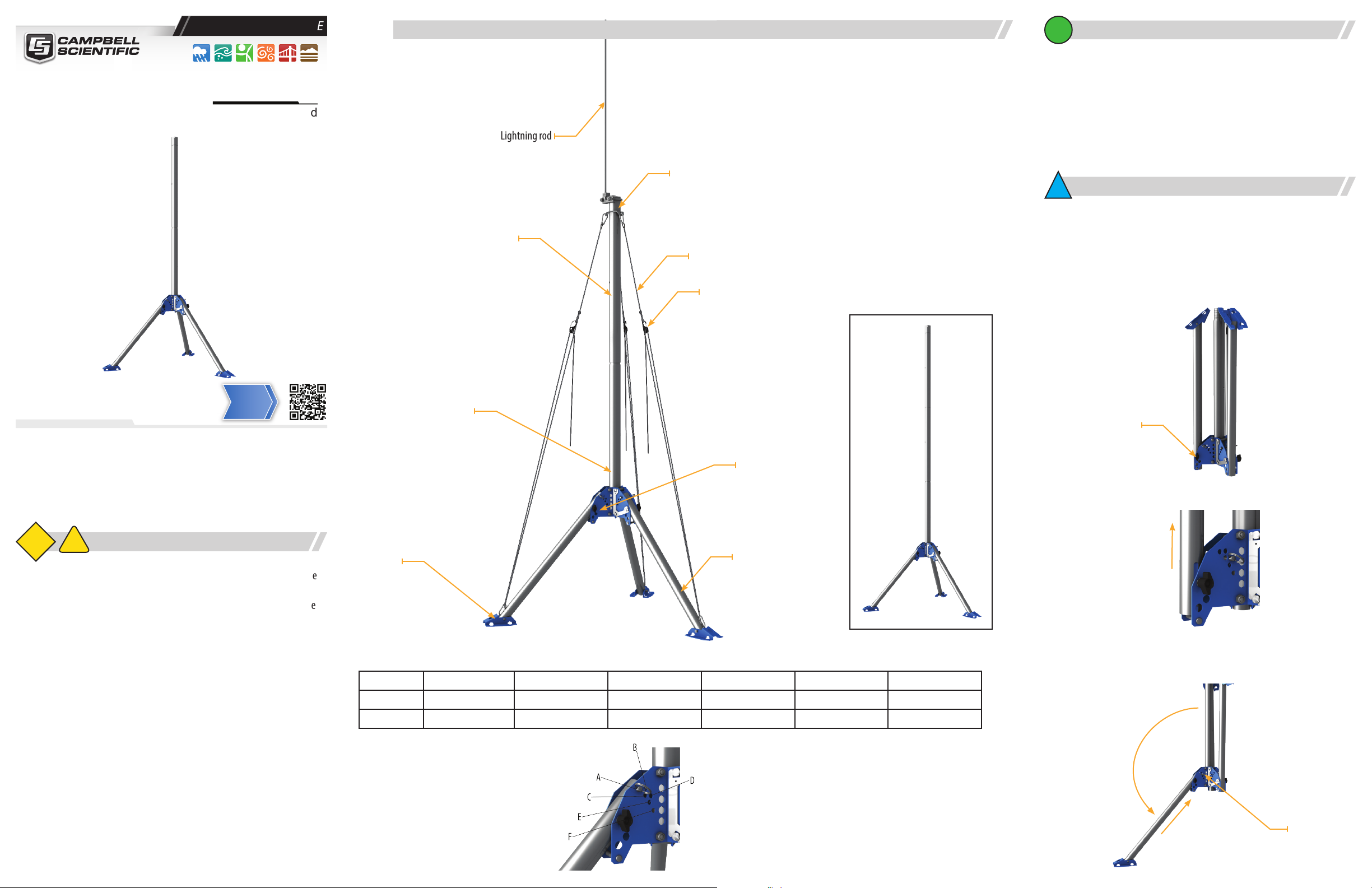
QST6 fully assembled with optional guy kit
Connecting Sensors
2
Required tools
The QST6 quick-setup tripod is designed to be assembled with minimal tools.
Document Part Number: 35358
Revision Date March 2021
QST6
Quick-Setup Tripod
Info
Link
Mast section
Lightning rod
Mast section
Top collar
Guy line
Buckle
QST6 with three mast sections
• A hammer is required to drive the ground rod into the ground.
• A screwdriver is needed to attach the ground wire to the lightning rod bracket
• A 1/2 inch open-end wrench or adjustable wrench is needed to secure the
lighting rod to the mast.
Physical deployment
3
Remove the QST6 from the packaging. Ensure all components are present before
assembling the tripod.
Tripod Assembly
1. Loosen the black tension knob securing one of the tripod legs.
Tension Knob
IMPORTANT NOTE: This Assemby Guide is meant to be a general
reference to give the installer an overview of the steps required to
make this tripod operational.
Caution!
1
• Ensure structural integrity during setup and weather extremes to minimize
the chance of damaging the tripod or instruments. Read all instructions
carefully. Once the tripod is in full vertical position, securely fasten it to the
ground using ground spikes or another method suitable for the soil at the
installation site.
• Maintain a distance of at least one-and-one-half times structure height,
20 feet, or the distance required by applicable law, whichever is greater,
between overhead utility lines and the structure (tripod, attachments, or
tools).
• Read all applicable instructions carefully and understand procedures
thoroughly before beginning work.
!
Tension knob
Foot
Leg
Table 1: Leg position dimensions
Hole A B C D E F
Height 179.5 cm (70.7 in) 174.5 cm (68.7 in) 170.3 cm (67.1 in) 164.4 cm (64.7 in) 158.7 cm (62.5 in) 145.1 cm (57.1 in)
Diameter 103.0 cm (40.5 in) 112.5 cm (44.3 in) 123.4 cm (48.6 in) 130.6 (51.4 in) 139.0 cm (54.7 in) 148.6 cm (58.5 in)
Outer Diameter (mast) : 4.8 cm (1.9 in)
Pipe Size (mast): 1.5 in. IPS sch 10
Leg Length: 66.0 cm (26 in)
Folded size: 71.1 x 20.3 x 20.3 cm (28 x 8 x 8 in)
Weight: 4 kg (9 lb)
Ratings
Tip over/pull out of screw earth anchors: 105 kph (65 mph) for pin hole F
74 kph (46 mph) for pin hole A
Maximum vertical load (exluding guy wire load): 22.7 kg (50 lb)
Guy wire tension: Pull ~14 kg (30 lb) on ropes, equals 28 kg (60 lb) tension
Maximum sustained wind load (guyed or unguyed): 97 kph (60 mph). The
guy wires add stability to the mast (less exing in high winds).
2. Slide the leg upward to free the notch on the end of the leg from the pin at
the bottom of the tripod frame.
3. Rotate the leg down until the notch on the end of the leg lines up with the
removable pin in the tripod frame. Slide the leg onto the pin until the notch is
fully engaged with the pin.
Removable Pin
Page 2
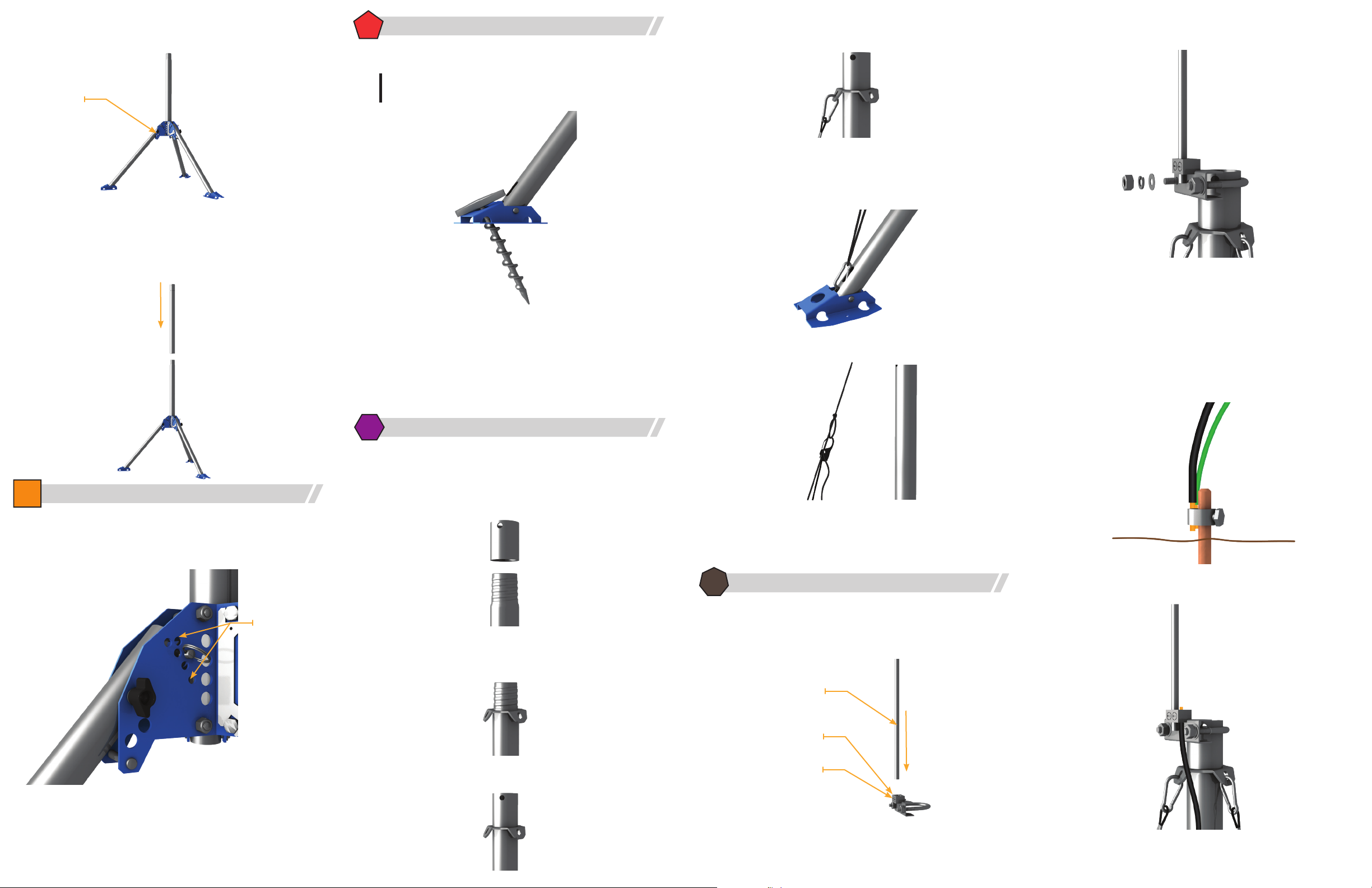
4. Tighten the black tension knob to secure the leg in the new position. Repeat
for the other two legs.
Tension Knob
5. A small amount of anti-seize lubricant is provided to apply to the mast
threads. The rst mast section is attached to the legs. Place the second mast
section on top of the rst. Turn the second section clockwise to thread it
onto the rst. If installing an optional third mast section, install the section
without the top collar rst, then thread the third section onto the second.
Anchoring the QST6
5
Anchoring the QST6 with the optional anchors
The QST6 may be anchored to the ground using three optional 9-inch T-Handle
screw anchors available from Campbell Scientic.
Note: Anchor the QST6 to the ground prior to installing the optional guy
kit. The guy line and clip may interefere with turning the anchor handle.
Place the tip of an anchor through the hole in the top of the foot. Turn the handle
clockwise, applying downward pressure, until the anchor fully secures the tripod
foot to the ground.
Some soil types may require additional anchors or longer stakes to secure the
tripod.
5. Connect the clip secured to one end of the guy line to one of the ns in the
guy ring.
6. Bring the guy line to the corresponding foot on the tripod. Attach the clip to
lower end of the tripod leg, routing the clip through the notch in the end of
the leg, then back up and through slot in the leg
7. Latch the buckle into the knotted hole near the top end of the guy line.
the collar. Tighten the two bolts so there is an equal length of U-bolt visible
at each end.
3. Place the ground clamp over the at end of the ground rod and tighten the
clamp.
4. Use a hammer to drive the ground rod into the ground, directly below the
tripod, until only the tip of the rod with the clamp is visible.
5. Attach one end of the 4 AWG copper ground wire (black insulation) to the
clamp on the ground rod. Also attach one end of the 10 AWG green ground
wire to the clamp. The green ground wire is used to ground an enclosure
when an enclosure is mounted on the tripod. Connect the other end of this
wire to the enclosure ground lug.
4
Leg adjustment
The QST6 legs have six possible positions to choose from when setting up the
tripod. Changing which hole is used will change the height of the tripod and the
diameter of the legs.
Leg adjustment
holes
6
Installing the optional guy kit
1. Unpackage the guy kit and separate the three guy lines.
2. Unscrew the top collar from the QST6. Holes are provided as points to insert
a screwdriver for additional leverage, if needed. If an optional third section
is installed, unscrew the top section from the second section instead of
removing the top collar.
3. Place the guy ring, with the ns angled down, over the top of the mast
section. Align the holes in the ns with the tripod legs
4. Reattach the top collar (or third mast section).
8. Pull the free end of the guy line downward to increase tension on the line.
9. Repeat for the other two guy lines.
10. Once all three guy lines are in place, increase tension on the guy lines to
secure the mast in place with equal tension on all three lines.
7
Grounding the QST6
Grounding the tripod.
1. Insert the at end of the lightning rod into one of the two holes on the lightning rod clamp. Tighten the set screw for that hole to secure the lightning
rod.
Lightning rod
clamp
Connecting Sensors
Lightning rod
Set screw
6. Secure the other end of the 4 AWG copper ground wire in the open hole in the
lightning rod clamp. Fully tighten the set screw to secure the wire.
Table 1 shows the height and diameter of the tripod at each each pin setting.
When the tripod is on level ground, each leg will use the same hole to keep the
tripod level. When the tripod is on a hill, point one leg directly downhill and move
the pins as needed to bring the tripod into vertical alignment.
2. Place the lightning rod over the top collar, sliding it on until there is approxi-
mately 1.25 cm (1/2 in) of clearance between the top of the U-bolt and top of
 Loading...