

Page 1

INSTRUCTION MANUAL
Q-7.1 Net Radiometer
Revision: 5/96
Copyright (c) 1991-1996
Campbell Scientific, Inc.
Page 2

Warranty and Assistance
The Q-7.1 NET RADIOMETER is warranted by CAMPBELL SCIENTIFIC,
INC. to be free from defects in materials and workmanship under normal use
and service for twelve (12) months from date of shipment unless specified
otherwise. Batteries have no warranty. CAMPBELL SCIENTIFIC, INC.'s
obligation under this warranty is limited to repairing or replacing (at
CAMPBELL SCIENTIFIC, INC.'s option) defective products. The customer
shall assume all costs of removing, reinstalling, and shipping defective products
to CAMPBELL SCIENTIFIC, INC. CAMPBELL SCIENTIFIC, INC. will
return such products by surface carrier prepaid. This warranty shall not apply
to any CAMPBELL SCIENTIFIC, INC. products which have been subjected to
modification, misuse, neglect, accidents of nature, or shipping damage. This
warranty is in lieu of all other warranties, expressed or implied, including
warranties of merchantability or fitness for a particular purpose. CAMPBELL
SCIENTIFIC, INC. is not liable for special, indirect, incidental, or
consequential damages.
Products may not be returned without prior authorization. The following
contact information is for US and International customers residing in countries
served by Campbell Scientific, Inc. directly. Affiliate companies handle repairs
for customers wi thin their territories. Please visi t www.campbellsci.com to
determine which Campbell Scientific company serves your country. To obtain
a Returned Materials Authorization (RMA), contact CAMPBELL
SCIENTIFIC, INC., phone (435) 753-2342. After an applications engineer
determines the nature of the problem, an RMA number will be issued. Please
write this number clearly on the outside of the shipping container.
CAMPBELL SCIENTIFIC's shipping address is:
CAMPBELL SCIENTIFIC, INC.
RMA#_____
815 West 1800 North
Logan, Utah 84321-1784
CAMPBELL SCIENTIFIC, INC. does not accept collect calls.
Page 3
Q-7.1 NET RADIOMETER
The Q-7.1 is a high-output thermopile sensor which measures the algebraic sum of incoming and
outgoing all-wave radiation (i.e. short-wave and long-wave components). Incoming radiation consists of
direct (beam) and diffuse solar radiation plus long-wave irradiance from the sky. Outgoing radiation
consists of reflected solar radiation plus the terrestrial long-wave component.
1. SPECIFICATIONS
• 60-junction thermopile with low electrical
resistance (4 ohms nominal) to reduce
susceptibility to noise
• Nominal calibration factors 9.6 W m
(for positive values), 11.9 W m
negative values)
• Spectral response 0.25 to 60 µm
• Uncorrected wind effect: up to 6%
reduction @ 7 m s
to 1% reduction @ 7 m s
-1
for positive fluxes, up
-1
for negative
fluxes.
-2
mV
-2 mV-1
1
-
(for
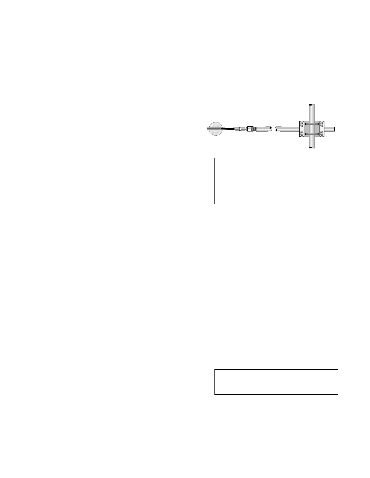
CAUTION: Ensure that the cable is tied to
the support arm close to the ball joint. If
the wires are allowed to flex where they
emerge from the sensor head they will
break. Sensors are shipped with an
appropriate cable tie already installed.
• Time constant: Approximately 30 seconds
• Top and bottom surfaces painted black and
protected from convective cooling by
hemispherical heavy-duty polyethylene
windshields (0.25 mm thick)
• Windshields do not require pressurization
• O-ring seals for easy windshield
replacement
• Desiccant contained in support arm;
volume of desiccant tube 45 cm
3
; breather
port on the end of the support arm.
• No power required
• Size of sensing head 57 x 72 x 177 mm;
support arm 20 mm diameter, 750 mm long
2. INSTALLATION
Attach the square mounting plate to a vertical or
horizontal pipe or rod that is less than 38 mm
(1.5 inches) in diameter with the two larger Ubolts. Attach the radiometer support arm to the
mounting plate with the two smaller U-bolts.
The radiometer support arm does not need to be
level. Fasten the cable to the pipe or rod with
tape or plastic ties to prevent strain on the wires
and damage to the instrument.
In the northern hemisphere install the
radiometer so that the sensor head is pointing
south. Likewise, in the southern hemisphere
point the sensor head to the north.
2.1 LEVELING
The Q-7.1 must be level. The bubble level is
accurate to ±1° and the bubble should be within
the bulls-eye. An error of 5° in leveling may
cause a cosine response error of 6% under
normal conditions; much greater errors are
possible under other conditions (e.g. sunrise,
sunset and winter use with low sun angles).
To level the Q-7.1, use a 5/8" wrench on the
hexagonal coupling nut on the instrument stem
to bend the ball joint between the support arm
and the instrument. If the instrument does not
stay in position, tighten the large hexagonal nut
on the support arm slightly with a 15/16"
wrench.
CAUTION: Do not attempt to bend the ball
joint by holding the instrument head alone,
as this may break the stem.
1
Page 4
Q-7.1 NET RADIOMETER
2.2 WIRING
If a differential measurement is made, connect
the red (+) lead to the high side (e.g. 1H) of any
datalogger differential channel and the black (-)
lead to the low side (e.g. 1L). Also, connect a
jumper wire between the low channel and
analog ground to prevent common mode
errors. Connect the clear (shield) lead to
ground (G on the CR10(X), ground on the 21X
and CR7).
If a single-ended measurement is made,
connect the red lead to any datalogger singleended channel (H or L) and the black lead to
ground (AG on the CR10(X), ground on the 21X
and CR7).
The black lead is negative with respect to the
red lead when the net radiometer is mounted
with the level up and there is more incoming
radiation than outgoing.
3. PROGRAMMING
Measure the output of the Q-7.1 with either
Instruction 2 (Differential Volts) or Instruction 1
(Single-Ended Volts). Use the 250 mV range
for the CR10(X) and the 500 mV range for the
21X or CR7. The slow integration with 60 Hz
rejection yields a more noise-free reading.
For still air, net radiation (Q*) can be computed
from the thermopile voltage (V
If V
> 0, Q*(Wm-2) = Vt(mV) x F
t
If Vt < 0, Q*(Wm-2) = Vt(mV) x F
) by:
t
p
n
where Fp and Fn are the positive and negative
calibration factors respectively.
The calibration factors and serial number are
given on a label under the sensor head.
The above formula give the correct readings
for conditions of zero wind speed. Additional
corrections can be applied to reduce errors for
non-zero wind speeds.
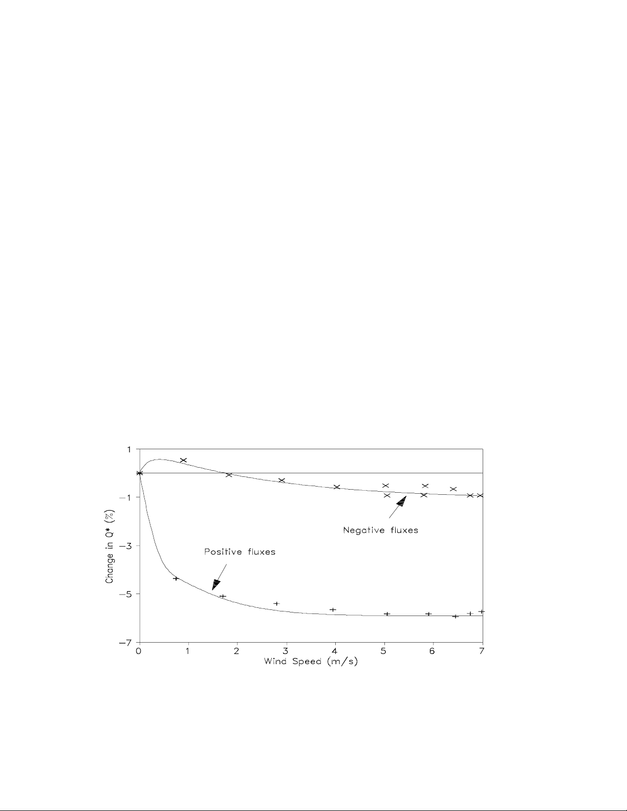
3.1 CORRECTING ERRORS CAUSED BY WIND EFFECT
Most sensors which measure long wave
radiation are subject to some degree of error
caused by convective cooling as air moves
past the sensors. The response of the Q-7.1
sensor has been determined by the
manufacturer using a specially constructed
wind tunnel. Curves fitted to experimental data
by the manufacturer are given in Figure 1.
These functions show the change in reading in
response to increasing wind speed.
FIGURE 1. Percentage Change in Reading as a Function of Wind Speed
2
Page 5

Q-7.1 NET RADIOMETER
FIGURE 2. Correction Functions as a Function of Wind Speed
The inverse of this data gives the required
correction factors to give the correct reading as
a function of wind speed (u). Figure 2 shows
the manufacturer’s data plus correction curves
fitted by Campbell Scientific, using functions
which can be easily encoded in a datalogger.
Note that the functions fitted and shown in both
graphs have been amended slightly to allow for
a small under-estimate of the error (about 2%
of the error) which is the result of a known error
of the calibration technique in the wind tunnel.
The correction function for positive fluxes is:
××
(. . )
Correction factor = 1 +
For negative fluxes a linear function is used:
Correction factor =
If the wind speed is not measured it is often
sufficient to correct the original calibration
constant using a fixed correction factor. The
manufacturer suggests using fixed correction
factors of 1.045 for positive fluxes and 1.000
for negative fluxes.
0 066 0 2
()
()
0 00174. ×
+×
..
0 066 0 2
u
u
()
u
+ 0.99755
If the wind speed is measured, the functions
above can be programmed into the datalogger
to give a real-time correction of net radiation
for the effects of wind speed. Note that the
wind speed is expressed in units of meters per
second. If the wind speed is measured in units
other than meters per second, convert the wind
speed to meters per second before inputting it
into the above correction functions.
If AC power is available, a special ventilator
(RV2) is available for the Q-7.1 which gives a
typical wind speed of 3.3 ms
negative fixed corrections are 1.06 and 1.0033
respectively. The fan is also useful for
reducing the risk of external condensation
(dew) on the windshields.
The above corrections were calculated at sea
level under conditions close to standard
temperature and pressure. The magnitude of
the wind speed error will vary in relation to the
air density and the heat capacity of air. These
changes are generally small enough to be
ignored unless extreme temperatures or
atmospheric pressures are experienced.
-1
. Positive and
3
Page 6

Q-7.1 NET RADIOMETER
3.2 PROGRAMMING EXAMPLE WITH FIXED WIND SPEED CORRECTION
The following CR10(X) program measures the
output of a Q-7.1. A static wind correction is
applied to each measurement.
Example 1. CR10(X) Program with the
Static Wind Speed Correction
;Measure the Q7.1.
;
01: Volt (Diff) (P2)***
1: 1 Reps
2: 24** ± 250 mV 60 Hz
Rejection Range
3: 1* DIFF Channel
4: 3* Loc [ Rn_W_m2 ]
5: 1 Mult
6: 0 Offset
02: IF (X<=>F) (P89)
1: 3* X Loc [ Rn_W_m2 ]
2: 3 >=
3: 0 F
4: 30 Then Do
;Enter the positive multiplier (p.ppp).
;
03: Z=X*F (P37)
1: 3* X Loc [ Rn_W_m2 ]
2:
3: 3* Z Loc [ Rn_W_m2 ]
04: Z=X*F (P37)
1: 3* X Loc [ Rn_W_m2 ]
2: 1.045 F
3: 3* Z Loc [ Rn_W_m2 ]
05: Else (P94)
p.ppp
F
;Enter the negative multiplier (n.nnn).
;
06: Z=X*F (P37)
1: 3* X Loc [ Rn_W_m2 ]
2:
3: 3* Z Loc [ Rn_W_m2 ]
07: End (P95)
n.nnn
F
3.3 PROGRAMMING EXAMPLE WITH DYNAMIC WIND SPEED CORRECTION
The following CR10(X) program measures an
R. M. Young wind sentry anemometer model
03101 and a Q-7.1. The wind speed is used to
give a real-time wind correction to net
radiation. The wind speed must be measured
before the wind corrections are applied.
Example 2. CR10(X) Program with the
Dynamic Wind Speed Correction
;Measure the 03101 wind sentry.
;
01: Pulse (P3)
1: 1 Reps
2: 1* Pulse Channel 1
3: 21 Low Level AC, Output Hz
4: 1* Loc [ ws_m_s ]
5: .75 Mult
6: .2 Offset
02: IF (X<=>F) (P89)
1: 1* X Loc [ ws_m_s ]
2: 1 =
3: .2 F
4: 30 Then Do
03: Z=F (P30)
1: 0 F
2: 0 Exponent of 10
3: 1* Z Loc [ ws_m_s ]
04: End (P95)
;Measure the Q7.1.
;
05: Volt (Diff) (P2)***
1: 1 Reps
2: 24** ± 250 mV 60 Hz
Rejection Range
3: 1* DIFF Channel
4: 2* Loc [ Rn_mV ]
5: 1 Mult
6: 0 Offset
* Proper entries will vary with program, and
datalogger channel and input location
assignments.
** On the 21X and CR7 use 500 mV input
range.
*** For a Single-Ended measurement use
Instruction 1.
4
06: IF (X<=>F) (P89)
1: 2* X Loc [ Rn_mV ]
2: 3 >=
3: 0 F
4: 30 Then Do
;Apply the positive calibration and
;wind speed correction.
;
Page 7

Q-7.1 NET RADIOMETER
07: Do (P86)
1: 1* Call Subroutine 1*
08: Else (P94)
;Apply the negative calibration and
;wind speed correction.
;
09: Do (P86)
1: 2* Call Subroutine 2*
10: End (P95)
*Table 3 Subroutines
;Positive calibration and wind
;speed correction.
;
01: Beginning of Subroutine (P85)
1: 1* Subroutine 1
02: Z=X*F (P37)
1: 1* X Loc [ ws_m_s ]
2: .2 F
3: 6* Z Loc [ C ]
03: Z=X*F (P37)
1: 6* X Loc [ C ]
2: .066 F
3: 4* Z Loc [ A ]
04: Z=X+F (P34)
1: 6* X Loc [ C ]
2: .066 F
3: 5* Z Loc [ B ]
09: End (P95)
;Negative calibration and wind
;speed corrections
;
10: Beginning of Subroutine (P85)
1: 2* Subroutine 2*
11: Z=X*F (P37)
1: 1* X Loc [ ws_m_s ]
2: .00174 F
3: 4* Z Loc [ A ]
12: Z=X+F (P34)
1: 4* X Loc [ A ]
2: .99755 F
3: 7* Z Loc [ Corr_Fact ]
;Enter the negative multiplier (n.nnn).
;
13: Z=X*F (P37)
1: 2* X Loc [ Rn_mV ]
2:
3: 3* Z Loc [ Rn_W_m2 ]
14: Z=X*Y (P36)
1: 3* X Loc [ Rn_W_m2 ]
2: 7* Y Loc [ Corr_Fact ]
3: 3* Z Loc [ Rn_W_m2 ]
15: End (P95)
* Proper entries will vary with program, and
datalogger channel and input location
assignments.
n.nnn
F
05: Z=X/Y (P38)
1: 4* X Loc [ A ]
2: 5* Y Loc [ B ]
3: 7* Z Loc [ Corr_Fact ]
06: Z=Z+1 (P32)
1: 7* Z Loc [ Corr_Fact ]
;Enter the positive multiplier (p.ppp).
;
07: Z=X*F (P37)
1: 2* X Loc [ Rn_mV ]
2:
3: 3* Z Loc [ Rn_W_m2 ]
08: Z=X*Y (P36)
1: 3* X Loc [ Rn_W_m2 ]
2: 7* Y Loc [ Corr_Fact ]
3: 3* Z Loc [ Rn_W_m2 ]
p.ppp
F
** On the 21X and CR7 use 500 mV input
range.
***For a Single-Ended measurement use
Instruction 1.
4. MAINTENANCE
4.1 DESICCANT
The Q-7.1 is supplied with heavy duty
polyethylene windshields (approximately 0.25
mm thick); no pressurization is required.
Air spaces inside the windshields are
connected to a dryer filled with silica gel
(referred to as the desiccant tube) to prevent
internal condensation. The desiccant tube is
located in the support arm and is accessible by
removing the end plug and vinal cap.
5
Page 8

Q-7.1 NET RADIOMETER
Inspect the silica gel monthly to ensure it is still
blue and white. If the color changes to pink
and white, replace it with dry silica gel (this
may have to be done more frequently in wet
weather). Wet (pink and white) silica gel can
be dried by removing it from the desiccant tube
and baking at 130°C until it returns to a blue
and white color. Remove the desiccant tube
end cap to remove and replace the silica gel.
CAUTION: After the desiccant tube has
been replaced, install the end plug and
vinal cap. Be sure the holes in the vinal
cap point towards the ground.
If the Q-7.1 is installed at a remote site it may
be convenient to have a spare desiccant tube
for quick replacement (be sure to remove the
outer end caps from both tube ends before
installing). Spare desiccant tubes are available
from Radiation Energy Balance Systems.
4.2 CONDENSATION
Condensation on net radiometer windshields
causes incorrect measurements. This is
because water does not transmit longwave
energy. An example of this problem can be
seen by comparing measured net radiation
values from two different net radiometers at
night, one on which dew is allowed to form and
another on which dew is prevented. Without
dew both instruments would indicate a similar
-2
net radiation level, e.g. -50 W m
. However,
on the instrument on which dew was allowed to
form a net radiation level of about zero would
be indicated, while the other radiometer would
-2
maintain the reading of -50 W m
. The RV2
ventilator can be used to prevent dew from
forming on the windshields.
4.2.1 Causes of Internal Condensation
If condensation develops inside the domes
check the following:
Desiccant
Make sure that the desiccant is dry (i.e. still
blue and white).
If it has turned pink, replace it with dry
desiccant or bake it until it is dry (see section
4.1 above). If the desiccant is pink only at the
tube end nearest the sensor head, this
indicates a leak somewhere on the sensor.
Windshields and O-rings
Check that the windshields and O-rings are in
good condition and are properly seated against
the radiometer frame (see below).
If there is still no obvious reason for the internal
condensation, check for possible leaks in the
sensor as follows:
1. Remove the desiccant tube.
2. Immerse the radiometer in water and blow
gently into the open end of the support
arm. A stream of bubbles will indicate the
location of any leaks.
3. Dry the instrument with a soft facial tissue.
If the windshields get dented, reinflate
them by blowing into the end of the support
arm.
CAUTION: When drying the windshields,
dabbing rather than wiping them will help to
prevent scratches.
4.2.2 Possible Internal Condensation
Problems After Installation
There is a small possibility that condensation
may occur on the inside of the windshields
when the Q-7.1 is first installed in the field.
This condensation is caused by evaporation of
hydrocarbon solvents used in the
manufacturing process and may be more
apparent after several hot, sunny days if
ambient temperatures are low enough.
If you notice condensation inside the
windshields after the first few days of sunshine
following installation, remove the windshields
as described below. Allow the solvent vapor or
condensation to escape or evaporate from the
inner air space for 15 minutes then replace the
windshields.
4.3 CLEANING
The windshields may be washed with a camel
hair brush or with a paper tissue and distilled
water.
CAUTION: Coarse paper or cloth will
scratch the windshields and should be
avoided.
6
Page 9

Q-7.1 NET RADIOMETER
4.4 WINDSHIELD REPLACEMENT
Polyethylene deteriorates with exposure to
solar radiation. Inspect the windshields
frequently and replace as required (probably
every 3-6 months).
Always check for:
1. Condensation inside the windshields,
possibly indicating a leak.
2. Cracking or crazing of the windshields
(which usually appears first along the base).
Prompt replacement is essential if any of these
conditions occur. Also, if the windshields are
removed for any reason after more than one
month’s use, replace them with new ones. The
windshields should always be replaced as a set.
Windshield replacement may cause a slight
change in calibration, although this is unlikely
to exceed 3%.
CAUTION: There are very fine wires
inside the head of the Q-7.1 which are very
susceptible to corrosion if subjected to
moisture, e.g. standing water. It is
essential to carry out the preemptive
maintenance mentioned above to prevent
serious damage to the sensor.
Replace the windshields as follows:
1. Remove the mounting screws and clamping
rings.
2. Replacement windshields are pre-cut and
punched with holes. Make sure the O-rings
are in their grooves before clamping the new
windshields into place as described in step
3.
3. Gently tighten the screws in the following
sequence: first, third, fifth, second, fourth,
sixth. It does not matter which screw you
treat as the first. Continue the sequence
until the windshields are evenly in contact
with the clamping rings and frame.
4. Tighten the screws in the same sequence
until no space remains between either
windshield flange and its corresponding
mounting ring or frame surface. Make sure
both upper and lower windshields are
completely seated on the frame around the
entire periphery.
CAUTION: Do not attempt to dismantle
the instrument body. If internal attention is
needed, contact Campbell Scientific, Inc.
for repair.
If the windshields become dented, remove the
dents as follows:
1. Remove the vinal cap from the support arm.
2. Blow gently into the end plug breather hole
to inflate the windshields.
Remember to replace the support arm vinal
cap. Orient the vinal cap so the holes point
towards the ground.
CAUTION: When replacing the
windshields, take great care not to touch or
mark the black surfaces of the thermopile
as this may affect the performance of the
instrument. Take care also to avoid
overtightening the mounting screws.
4.4.1 Bird Damage
One other cause of damage to windshields is
birds pecking at the domes. A simple measure
to prevent this is to attach two or three 8 inches
cable ties to the support arm at the end near
the sensor head, with the free ends of the ties
pointing upwards to form an array of ‘spikes’.
This may discourage birds from landing on the
arm. If this does not work you may have to
resort to more drastic techniques such as
installing an artificial snake on the support arm
or commercial bird scarers.
4.5 CALIBRATION
Q-7.1 net radiometers show excellent stability
over long periods, but for serious use, regular
calibration checks are recommended. The
calibration can be checked in the field by
mounting another net radiometer alongside and
comparing results. The instruments should be
examined carefully if the results differ by more
than a few percent. Under normal
circumstances, a calibration check every six
months is adequate providing the sensitive
thermopile surface has not been marked,
damaged or exposed to the weather.
If the calibration can not be checked in the
field, Radiation Energy Balance Systems
7
Page 10

Q-7.1 NET RADIOMETER
recommends recalibration every six months,
depending on the climate where the sensors
are used.
Each instrument is calibrated by the
manufacturer in a temperature-controlled
calibration chamber by comparison to a
transfer standard. The chamber uses a
combination of tungsten-halide source and
black body chambers. The transfer standard is
calibrated by comparison to a precision
pyranometer using a partial shading technique
developed by Radiation Energy Balance
Systems. The long wave calibration of the
standard has also been verified using black
body chambers.
Care should, however, be taken when
comparing readings with sensors from different
manufacturers or even older models from
Radiation Energy Balance Systems. This is
because in recent years academic studies have
reported inadequacies both in the design and
calibration of net radiometers from most
manufacturers. Radiation Energy Balance
Systems aim to keep at the forefront of such
developments and have published corrections
for the calibration of older sensors. However,
these corrections cannot fully bring the
instruments to the same level of performance
as the new sensors. It is, however, possible to
upgrade and recalibrate the sensor heads of
older models.
8
Page 11

This is a bla nk page.
Page 12

Campbell Scientific Companies
Campbell Scientific, Inc. (CSI)
815 West 1800 North
Logan, Utah 84321
UNITED STATES
www.campbellsci.com
info@campbellsci.com
Campbell Scientific Africa Pty. Ltd. (CSAf)
PO Box 2450
Somerset West 7129
SOUTH AFRICA
www.csafrica.co.za
sales@csafrica.co.za
Campbell Scientific Australia Pty. Ltd. (CSA)
PO Box 444
Thuringo wa Cent ra l
QLD 4812 AUSTRALIA
www.campbellsci.com.au
info@campbellsci.com.au
Campbell Scientific do Brazil Ltda . (CSB)
Rua Luisa Crapsi Orsi, 15 Butantã
CEP: 005543-000 São Paulo SP BRAZIL
www.campbellsci.com.br
suporte@campbellsci.com.br
Campbell Scientific Canada Corp. (CSC)
11564 - 149th Street NW
Edmonton, Alberta T5M 1W7
CANADA
www.campbellsci.ca
dataloggers@campbellsci.ca
Campbell Scientific Ltd. (CSL)
Campbell Park
80 Hathern Road
Shepshed, Loughborough LE12 9GX
UNITED KINGDOM
www.campbellsci.co.uk
sales@campbellsci.co.uk
Campbell Scientific Ltd. (France)
Miniparc du Verger - Bat. H
1, rue de Terre Neuve - Les Ulis
91967 COURTABOEUF CEDEX
FRANCE
www.campbellsci.fr
campbell.scientific@wanadoo.fr
Campbell Scientific Spain, S. L.
Psg. Font 14, local 8
08013 Barcelona
SPAIN
www.campbellsci.es
info@campbellsci.es
Please visit www.campbellsci.com to obtain contact information for your local US or International representative.
 Loading...