

Page 1
P2546A-L Anemometer
8/12
Copyright © 2012
Campbell Scientific, Inc.
Page 2

Page 3

Warranty
“PRODUCTS MANUFACTURED BY CAMPBELL SCIENTIFIC, INC. are
warranted by Campbell Scientific, Inc. (“Campbell”) to be free from defects in
materials and workmanship under normal use and service for twelve (12)
months from date of shipment unless otherwise specified in the corresponding
Campbell pricelist or product manual. Products not manufactured, but that are
re-sold by Campbell, are warranted only to the limits extended by the original
manufacturer. Batteries, fine-wire thermocouples, desiccant, and other
consumables have no warranty. Campbell's obligation under this warranty is
limited to repairing or replacing (at Campbell's option) defective products,
which shall be the sole and exclusive remedy under this warranty. The
customer shall assume all costs of removing, reinstalling, and shipping
defective products to Campbell. Campbell will return such products by surface
carrier prepaid within the continental United States of America. To all other
locations, Campbell will return such products best way CIP (Port of Entry)
INCOTERM® 2010, prepaid. This warranty shall not apply to any products
which have been subjected to modification, misuse, neglect, improper service,
accidents of nature, or shipping damage. This warranty is in lieu of all other
warranties, expressed or implied. The warranty for installation services
performed by Campbell such as programming to customer specifications,
electrical connections to products manufactured by Campbell, and product
specific training, is part of Campbell’s product warranty. CAMPBELL
EXPRESSLY DISCLAIMS AND EXCLUDES ANY IMPLIED
WARRANTIES OF MERCHANTABILITY OR FITNESS FOR A
PARTICULAR PURPOSE. Campbell is not liable for any special, indirect,
incidental, and/or consequential damages.”
33
Page 4

Assistance
Products may not be returned without prior authorization. The following
contact information is for US and international customers residing in countries
served by Campbell Scientific, Inc. directly. Affiliate companies handle
repairs for customers within their territories. Please visit
www.campbellsci.com to determine which Campbell Scientific company serves
your country.
To obtain a Returned Materials Authorization (RMA), contact CAMPBELL
SCIENTIFIC, INC., phone (435) 227-9000. After an applications engineer
determines the nature of the problem, an RMA number will be issued. Please
write this number clearly on the outside of the shipping container. Campbell
Scientific's shipping address is:
CAMPBELL SCIENTIFIC, INC.
RMA#_____
815 West 1800 North
Logan, Utah 84321-1784
For all returns, the customer must fill out a "Statement of Product Cleanliness
and Decontamination" form and comply with the requirements specified in it.
The form is available from our web site at www.campbellsci.com/repair. A
completed form must be either emailed to repair@campbellsci.com or faxed to
(435) 227-9106. Campbell Scientific is unable to process any returns until we
receive this form. If the form is not received within three days of product
receipt or is incomplete, the product will be returned to the customer at the
customer's expense. Campbell Scientific reserves the right to refuse service on
products that were exposed to contaminants that may cause health or safety
concerns for our employees.
Page 5

Table of Contents
PDF viewers: These page numbers refer to the printed version of this document. Use the
PDF reader bookmarks tab for links to specific sections.
1. Introduction.................................................................1
2. Cautionary Statements...............................................1
3. Initial Inspection .........................................................1
4. Quickstart .................................................................... 2
4.1 Step 1 — Mount the Sensor .................................................................2
4.2 Step 2 — Use SCWin ShortCut to Program Datalogger and
Generate Wiring Diagram.................................................................3
5. Overview......................................................................5
6. Specifications .............................................................6
6.1 Calibration............................................................................................7
6.2 Switching Characteristics.....................................................................7
7. Installation...................................................................7
7.1 Wiring ..................................................................................................7
7.2 Programming........................................................................................8
7.2.1 Example Program..........................................................................9
8. Troubleshooting........................................................10
9. Maintenance ..............................................................10
10. References ................................................................11
Figures
4-1. 27739 pole mounted to a crossarm via the CM220..............................2
5-1. P2546A Anemometer...........................................................................5
Tables
7-1. Connections to Campbell Scientific Dataloggers Pulse Channels .......8
7-2. Connections to Campbell Scientific Dataloggers Control Ports...........8
7-3. Wind Speed Multiplier and Offset .......................................................9
i
Page 6

Page 7

P2546A-L Anemometer
1. Introduction
The P2546A is a Class 1 anemometer used in wind energy applications. It
primarily provides wind speed resource assessment, and wind turbine power
performance monitoring. Wind speed is sensed by a three-cup rotor assembly.
Magnets mounted on the shaft cause a switch to close and open two times per
revolution. Our dataloggers measure the switch closure and convert the signal
to engineering units (mph, m/s, knots).
Before using the P2546A-L Anemometer, please study
• Section 2. Cautionary Statements
• Section 3. Initial Inspection
• Section 4. Quickstart
More details are available in the remaining sections.
2. Cautionary Statements
• The P2546A is a precision instrument. Please handle it with care.
• If the P2546A is to be installed at heights over 6 feet, be familiar with
tower safety and follow safe tower climbing procedures.
• Danger — Use extreme care when working near overhead electrical wires.
Check for overhead wires before mounting the P2546A or before raising a
tower.
3. Initial Inspection
• Upon receipt of the P2546A, inspect the packaging and contents for
damage. File damage claims with the shipping company. Immediately
check package contents against the shipping documentation. Contact
Campbell Scientific about any discrepancies.
• The model number and cable length are printed on a label at the
connection end of the cable. Check this information against the shipping
documents to ensure the expected product and cable length are received.
• Each P2546A anemometer is shipped with a MEASNET calibration
certificate that contains information concerning where the anemometer
was calibrated, the calibration procedure used, the calibration equation
obtained, and the serial number of the anemometer. Cross check the serial
number in the calibration certificate against the serial number on the
anemometer to ensure that the given sensitivity value corresponds to your
sensor.
1
Page 8

P2546A-L Anemometer
4. Quickstart
4.1 Step 1 — Mount the Sensor
To mount the sensor, do the following.
1. Mount a CM202, CM204, or CM206 crossarm to a tripod or tower.
2. Orient the crossarm north-south, with the CM220 Mount on the north end.
3. Place the 27739 30 inch pole in the bottom of the P2546A.
4. Place the bottom of the 27739 pole in the CM220's u-bolt and tighten the
nuts (see FIGURE 4-1).
5. Use a bubble level to ensure that the anemometer is level.
6. Route the sensor cable along the underside of the crossarm to the tripod or
tower, and to the instrument enclosure.
7. Secure the cable to the 27739 pole, crossarm, and tripod or tower using
cable ties.
2
FIGURE 4-1. 27739 pole mounted to a crossarm via the CM220
Page 9

P2546A-L Anemometer
4.2 Step 2 — Use SCWin ShortCut to Program Datalogger and Generate Wiring Diagram
The simplest method for programming the datalogger to measure an P2546A is
to use Campbell Scientific's SCWin Short Cut Program Generator.
1. Open Short Cut and click on New Program.
2. Select datalogger and enter scan interval.
3
Page 10

P2546A-L Anemometer
3. Select P2546A and select the right arrow to add it to the list of sensors to
be measured then select next.
4. Select the outputs then select finish.
4
Page 11

P2546A-L Anemometer
5. Wire according to the wiring diagram generated by SCWin Short Cut.
5. Overview
The P2546A-L cup anemometer is a sturdy device that senses wind speed with
a three-cup rotor assembly (see FIGURE 5-1). Permanent magnets mounted on
the shaft cause a switch to close and open two times per revolution. The switch
has no bounce, and is equipped with a special mechanism that reduces the
variation in operating time over the frequency range. This feature facilitates
obtaining instantaneous wind speed by measuring the time interval of each
revolution.
FIGURE 5-1. P2546A Anemometer
5
Page 12

P2546A-L Anemometer
The P2546A anemometer is manufactured by Windsensor and cabled by
Campbell Scientific. Lead length for the P2546A is specified when the sensor
is ordered.
The P2546A's cable can terminate in:
6. Specifications
Features:
• Pigtails that connect directly to a Campbell Scientific datalogger
(option –PT).
• Connector that attaches to a prewired enclosure (option –PW). Refer
to www.campbellsci.com/prewired-enclosures for more information.
• Calibration — The P2546A-L is shipped with a MEASNET
certificate containing information about where the anemometer was
calibrated, the calibration procedure used, the calibration equation
obtained, and the serial number of the anemometer.
• Quality — Constructed only of durable materials such as anodized
aluminum and stainless steel.
NOTE
Compatibility
Dataloggers: CR800 / 850, CR1000, CR3000, CR5000,
CR10(X), CR510, CR23X, 21X, CR7
The specifications are based on 80 wind tunnel calibrations
performed according to the Measnet Cup Anemometer
Calibration Procedure. The specified offset and gain figures
represent the mean values of these calibrations. Variation among
units designates the maximum deviation of any unit from the
straight line representing these mean values. All units are run-in
for 225 hours at 9 m/s, in order to reduce the initial bearing
friction to a level close to the steady state value. After run-in,
bearing friction is tested at –15 °C and at room temperature. The
allowed limits for this test assures that the temperature influence
on the calibration is within the specified limit.
Starting Threshold: < 0.4 m/s
Starting Speed: 0.27 m/s
Gain: 0.6201 m
Distance Constant: λ0 = 1.81 ± 0.04 m
6
Standard Deviation of Offset: 0.014 m/s
Standard Deviation of Gain: 0.027 m
Variation Among Units: ±1%
Page 13

Nonlinearity: < 0.04 m/s
Temperature Influence
(-15° to 60°C): < 0.05 m/s
6.1 Calibration
Standard: U=A0+B0×f ,
Where:
U=Wind speed in m/s
f = Output frequency in Hz
A0 = 0.27 m/s
B
6.2 Switching Characteristics
Signal Type: potential free contact closure
Duty Cycle: 40% to 60%
Maximum Switching Voltage: 30 V
= 0.620 m
0
P2546A-L Anemometer
7. Installation
7.1 Wiring
Maximum Recommended
Switching Current: 10 mA
Series Resistance: 330 Ω, 1 W
Operating Temperature: –35° to 60°C
Locate wind sensors away from obstructions (e.g., trees and building). As a
general rule, there should be a horizontal distance of at least ten times the
height of the obstruction between the wind set and the obstruction. If mounting
the sensors on the roof of a building, the height of the sensors above the roof
should be at least 1.5 times the height of the building. See Section 10 for a list
of references that discuss siting wind speed and direction sensors. For power
performance applications, refer to IEC 61400-12-1 which specifies the
mounting and location of anemometers.
Connections to Campbell Scientific dataloggers are given in TABLE 7-1 and
TABLE 7-2. When Short Cut program generator software is used to create the
datalogger program, wire the sensor to the datalogger as directed by the wiring
diagram created by Short Cut.
7
Page 14
P2546A-L Anemometer
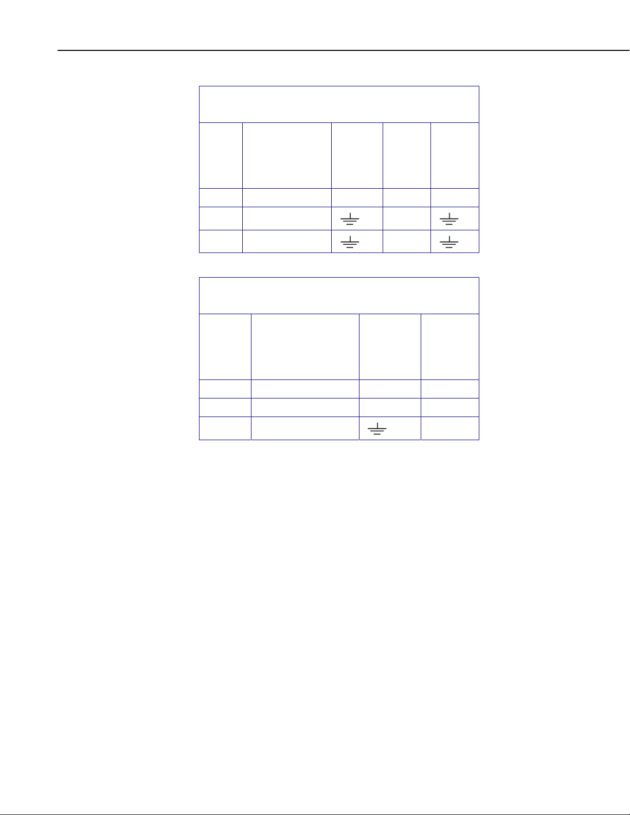
TABLE 7-1. Connections to Campbell Scientific Dataloggers
Pulse Channels
Color
White Signal Pulse Pulse Pulse
Brown Signal Reference
Clear Shield
TABLE 7-2. Connections to Campbell Scientific Dataloggers
Color
White Signal C1-C8 C6-C8
Brown Signal Reference 5V 5V
Clear Shield
Wire Label
Wire Label
CR800
CR850
CR5000
CR3000
CR1000
Control Ports
CR510
CR500
CR10X
G
G
CR800
CR850
CR5000
CR3000
CR1000
21X
CR7
CR23X
CR10X
G
8
7.2 Programming
This section is for users who write their own programs. A datalogger program
to measure this sensor can be created using Campbell Scientifics’ Short Cut
Program Builder software. You do not need to read this section to use Short
Cut.
Wind speed is typically measured an a datalogger pulse channel. The P2546A
uses the CRBasic PulseCount() instruction configuring the pulse channel for
switch closure with frequency counting. For dataloggers programmed with
EDLOG, specify configuration code 22 to output frequency in Hertz.
The expression for wind speed (U) is:
U = MX + B
where
M = multiplier
X = number of pulses per second (Hertz)
B = offset
Page 15

The following table lists the multiplier and offset to obtain meters per second
(m/s) when the pulse count instruction is configured to output the result in Hz.
Standard Calibration is listed below. Using the MEASNET calibration will
give measurements in m/s. MEASNET calibration multiplier and offset will
be listed on the MEASNET calibration sheet included with each sensor.
Model m/s
P2546A Multiplier = 0.6207
7.2.1 Example Program
The following CR1000 example program uses a pulse port to measure the
P2546A once a second. The program stores the mean, maximum, minimum,
and standard deviation of the measured wind speed over a 10 minute interval.
Wiring for the example is given in the following table.
P2546A-L Anemometer
TABLE 7-3. Wind Speed Multiplier and Offset
Offset = 0.27
'Pulse Port Example
'CR1000 Series Datalogger
'Program to measure P2546A and store ten minute averages
'Wiring
' Datalogger
'Color Description Channel
'----- ----------- -------
'Brown Signal Reference P1
'White Signal
'Clear Shield
Const P2546A_mult = .6201
Const p2546a_offset = .27
Public PTemp, batt_volt
Public P2546A
'Define Data Tables
DataTable (Test,1,1000)
DataInterval (0,10,Min,10)
Minimum (1,batt_volt,FP2,0,False)
Sample (1,PTemp,FP2)
Average (1,P2546A,FP2,False)
Maximum (1,P2546A,FP2,False,False)
Minimum (1,P2546A,FP2,False,False)
StdDev (1,P2546A,FP2,False)
EndTable
'Main Program
BeginProg
Scan (1,Sec,0,0)
PanelTemp (PTemp,250)
Battery (batt_volt)
'Measure P2546A and correct measurement if wind speed is zero
PulseCount (P2546A,1,1,2,1,P2546A_mult,p2546a_offset)
If P2546A <= p2546a_offset Then P2546A = 0
9
Page 16

P2546A-L Anemometer
'Call data tables
CallTable Test
NextScan
EndProg
8. Troubleshooting
Symptom: No wind speed
1. Check that the sensor is wired to the pulse channel specified by the pulse
count instruction.
2. Verify that the Configuration Code, and Multiplier and Offset parameters
for the Pulse Count instruction are correct for the datalogger type.
Symptom: Wind speed does not change
1. For the dataloggers that are programmed with Edlog, the input location for
wind speed is not updated if the datalogger is getting “Program Table
Overruns”. Increase the execution interval (scan rate) to prevent overruns.
9. Maintenance
Every month do a visual/audio inspection of the anemometer at low wind
speeds. Verify that the anemometer bearing rotate freely. Inspect the sensor
for physical damage. Replace the anemometer bearings when they become
noisy, or the wind speed threshold increases above an acceptable level.
CAUTION
Disassembling an anemometer to change the bearings will
invalidate the MEASNET calibration.
MEASNET calibrations are normally valid for 12 months in the field
(assuming the anemometer is installed within 6 months of the calibration test).
In high-accuracy applications, Campbell Scientific recommends that the
anemometer be returned to us for maintenance/overhaul between deployments;
we can arrange for a new MEASNET calibration after maintenance/overhaul
where required.
Before the anemometer is sent to Campbell Scientific, the customer must get
an RMA (returned material authorization) and fill out the Declaration of
Hazardous Material and Decontamination form.
10
Page 17

10. References
P2546A-L Anemometer
IEC 61400 Part 12-1, “Wind turbine generator systems Part 12: Wind Turbine
Power Performance Testing”.
The following references give detailed information on siting wind speed and
wind direction sensors.
EPA, 1989: Quality Assurance Handbook for Air Pollution Measurements
System, Office of Research and Development, Research Triangle Park,
NC, 27711.
EPA, 1987: On-Site Meteorological Program Guidance for Regulatory
Modeling Applications, EPA-450/4-87-013, Office of Air Quality Planning
and Standards, Research Triangle Park, NC 27711.
The State Climatologist, 1985: Publication of the American Association of
State Climatologists: Height and Exposure Standards, for Sensors on
Automated Weather Stations, vol. 9, No. 4.
WMO, 1983: Guide to Meteorological Instruments and Methods of
Observation, World Meteorological Organization, No. 8, 5th edition,
Geneva, Switzerland.
11
Page 18

P2546A-L Anemometer
12
Page 19

Page 20

Campbell Scientific Companies
Campbell Scientific, Inc. (CSI)
815 West 1800 North
Logan, Utah 84321
UNITED STATES
www.campbellsci.com
Campbell Scientific Africa Pty. Ltd. (CSAf)
Somerset West 7129
SOUTH AFRICA
www.csafrica.co.za
Campbell Scientific Australia Pty. Ltd. (CSA)
Garbutt Post Shop QLD 4814
www.campbellsci.com.au
Campbell Scientific do Brazil Ltda. (CSB)
Rua Luisa Crapsi Orsi, 15 Butantã
CEP: 005543-000 São Paulo SP BRAZIL
www.campbellsci.com.br
Campbell Scientific Canada Corp. (CSC)
11564 - 149th Street NW
Edmonton, Alberta T5M 1W7
www.campbellsci.ca
Campbell Scientific Centro Caribe S.A. (CSCC)
300 N Cementerio, Edificio Breller
Santo Domingo, Heredia 40305
www.campbellsci.cc
Campbell Scientific Ltd. (CSL)
Shepshed, Loughborough LE12 9GX
UNITED KINGDOM
www.campbellsci.co.uk
Campbell Scientific Ltd. (France)
3 Avenue de la Division Leclerc
www.campbellsci.fr
Campbell Scientific Spain, S. L.
Avda. Pompeu Fabra 7-9, local 1
www.campbellsci.es
Please visit www.campbellsci.com to obtain contact information for your local US or interna tional representative.
• info@campbellsci.com
PO Box 2450
• cleroux@csafrica.co.za
PO Box 8108
AUSTRALIA
• info@campbellsci.com.au
• suporte@campbellsci.com.br
CANADA
• dataloggers@campbellsci.ca
COSTA RICA
• info@campbellsci.cc
Campbell Park
80 Hathern Road
• sales@campbellsci.co.uk
92160 ANTONY
FRANCE
• info@campbellsci.fr
08024 Barcelona
SPAIN
• info@campbellsci.es
 Loading...