

Page 1

INSTRUCTION MANUAL
Interfacing the
OBS-3 Turbidity Monitor with
Campbell Scientific Dataloggers
10/05
Copyright (c) 1998-2005
Campbell Scientific, Inc.
Page 2

Disclaimer
This manual concerns interfacing another manufacturer’s product with our
dataloggers. We will attempt to provide accurate and up-to-date information in
this manual. However, changes to another manufacturer’s product are beyond
our control. Such changes may affect hookup, programming, and even safe
use of the product. Also, this manual should be used in conjunction with the
original manufacturer’s technical reference documentation. See their
documentation for information concerning product use and safety. If you
encounter out-of-date, incomplete, or incorrect information, please contact us
so we can attempt to remedy the situation.
Because the product is manufactured by another company, their warranty
applies. Contact the original manufacturer for warranty information, repairs,
and recalibrations.
Our website (http://www.campbellsci.com) lists the updated manuals.
Page 3

OBS-3 Table of Contents
PDF viewers note: These page numbers refer to the printed version of this document. Use
the Adobe Acrobat® bookmarks tab for links to specific sections.
1. Connections.................................................................1
2. Programming ...............................................................3
2.1 Using Short Cut........................................................................................3
2.2 Using Edlog or the Keyboard/Display......................................................3
2.3 Edlog Program Example...........................................................................3
2.4 CRBasic Program Example...................................................................... 5
3. Maintenance and Troubleshooting ............................5
Figures
1. Wiring Diagram of OBS-3 Using Datalogger’s Switched 12 V.................1
2. Wiring Diagram of OBS-3 without Using Switched 12 V.........................2
3. Wiring Diagram for Connecting an OBS-3 to an External Relay
and a Datalogger....................................................................................2
i
Page 4

This is a blank page.
Page 5
Interfacing the OBS-3 Turbidity Monitor with Campbell Scientific Dataloggers
The OBS-3 Turbidity Monitor is a submersible probe manufactured and sold by D & A
Instrument Company. This application note provides a diagram of connecting the OBS-3
to a CR1000, CR10(X), CR23X, and CR510 datalogger and describes programming a
datalogger to read this probe.
The standard output for the OBS-3 is 0 to 5 V, which may be used with the CR23X and
CR1000. If response over 1000 FTU is needed for use with the CR10(X) or CR510
datalogger, order the probe with the optional 0 to 2500 mV output range.
NOTE
1. Connections
When turbidity is very high, the OBS-3 probe can generate an
output greater than 5 V. To avoid the loss of data, ask D & A
Instruments to install a voltage limiting circuit in the probe that
clamps the output to 2.5 V or 5.0 V.
The OBS-3 probe may draw over 30 mA. Because this power
requirement is relatively high, we recommend you provide
switched power, such as the switched 12 V on the CR10X,
CR1000, and CR23X wiring panel. If power to the sensor is
continuous, you must use AC power or a solar panel with
excellent solar availability to maintain a good charge on the
battery.
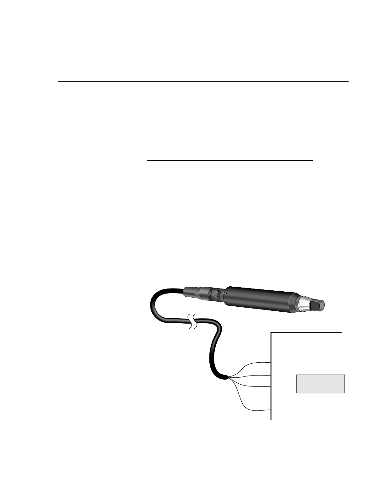
Red
White
Green
Black
FIGURE 1. Wiring Diagram of OBS-3 Using
Datalogger’s Switched 12 V
SW 12V
1H
1L
G
CR1000
1
Page 6

Interfacing the OBS-3 Turbidity Monitor with Campbell Scientific Dataloggers
Red
White
Green
Jumper
Black
12V
1H
1L
G
G
CR510, CR500
CR510
&
&
21X
21X
FIGURE 2. Wiring Diagram of OBS-3 without Using Switched 12 V
Red
- Load +
#7321
RELAY
- Control +
Black
White
Green
Jumper
12v
C1
G
G
1H
1L
G
Datalogger
2
NOTE
FIGURE 3. Wiring Diagram for Connecting an OBS-3 to
an External Relay and a Datalogger
1. The assignment of channel number (e.g., Diff Channel 1 or
C1) may vary depending on the application.
2. You may use a relay such as Campbell Scientific part #7321
instead of the switched 12 V connection on the CR10(X),
CR1000, and CR23X wiring panel. Since the CR510 wiring
panels do not have switched 12 V, you will need an external
relay if you need to conserve battery power.
Page 7

Interfacing the OBS-3 Turbidity Monitor with Campbell Scientific Dataloggers
2. Programming
2.1 Using Short Cut
2.2 Using Edlog or the Keyboard/Display
Use Short Cut, Edlog, or the keyboard/display to program the datalogger to
read the OBS-3 probe.
Short Cut is the easiest and typically the preferred method for programming the
datalogger. With Short Cut, you choose the OBS-3 pr obe and your output
preferences from a series of menus, then Short Cut creates a custom program
and wiring diagram for you.
Edlog dataloggers: Use Instruction 2--Differential Voltage to read the probe’s
millivolt signal. This instruction requires a multiplier to be calculated. The
multiplier is the full scale FTU value divided by the probe’s full scale millivolt
output. Typically, the offset is zero.
CRBasic dataloggers: Use VoltDiff instruction to read the probe’s millivolt
signal. This instruction requires a multiplier to be calculated. The multiplier
is the full scale FTU value divided by the probe’s full scale millivolt output.
Typically, the offset is zero.
2.3 Edlog Program Example
The program on the following page reads an OBS-3 probe that’s using
switched 12 V power, either built-in or using an external relay. The program
could be used for a CR10(X) or CR510. Except for parameters 2 and 5 in
Instruction 2 (Differential Voltage), the 21X and CR23X programs are the
same. The appropriate parameters for the 21X and CR23X are displayed in
bold lettering.
;Program to read OBS-3 Turbidity Monitor with 0 to 2500 mV output
;and 2000 FTU.
*Table 1 Program
;Pick the execution interval you need. Five seconds is OK for testing.
01: 5.0 Execution Interval (seconds)
;Power-up probe and provide warm-up time
1: Do (P86)
1: 41 Set Port 1 High ; Port number corresponds to C1
2: Excitation with Delay (P22)
1: 1 Ex Channel
2: 0 Delay W/Ex (units = 0.01 sec)
3: 100 Delay After Ex (units = 0.01 sec)
4: 0 mV Excitation
3
Page 8

Interfacing the OBS-3 Turbidity Monitor with Campbell Scientific Dataloggers
;Read millivolt signal
3: Volts (DIFF) (P2)
1: 1 Reps
2: 25 2500 mV 60 Hz Rejection Range ;CR23X is 25 ± 5000 mV 60 Hz Rejection Range
3: 1 DIFF Channel
4: 1 Loc [ Turbidity ]
5: 0.8 Mult ;(2000 FTU)/(2500 mV) CR23X would be 2000/5000 = 0 .4
6: 0.0 Offset
;Remove power from probe
4: Do (P86)
1: 51 Set Port 1 Low
;Measure system voltage
5: Batt Voltage (P10)
1: 2 Loc [ BATT_VOLT ]
;Output every hour the date and the average turbidity, maximum
;turbidity with the time of occurrence, and battery voltage.
6: If time is (P92)
1: 0 Minutes into a
2: 60 Interval
3: 10 Set Output Flag High
7: Real Time (P77)
1: 1110 Year, Day, Hour/Minute
8: Average (P71)
1: 1 Reps
2: 1 Loc [ Turbidity ]
9: Maximize (P73)
1: 1 Reps
2: 10 Value with Hr_Min
3: 1 Loc [Turbidity ]
10: Sample (P70)
1: 1 Reps
2: 2 Loc [ BATT_VOLT ]
4
Page 9

Interfacing the OBS-3 Turbidity Monitor with Campbell Scientific Dataloggers
2.4 CRBasic Program Example
'CR1000
'Declare Variables and Units
Public Batt_Volt
Public FTU
Units Batt_Volt=Volts
'Define Data Tables
DataTable(Table1,True,-1)
DataInterval(0,60,Min,10)
Average(1,FTU,IEEE4,False)
Maximum(1,FTU,IEEE4,False,True)
EndTable
DataTable(Table2,True,-1)
DataInterval(0,1440,Min,10)
Minimum(1,Batt_Volt,FP2,False,False)
EndTable
'Main Program
BeginProg
Scan(30,Min,1,0)
'Default Datalogger Battery Voltage measurement Batt_Volt:
Battery(Batt_Volt)
'OBS-3 Turbidity Probe (D&A Instruments) measurement FTU:
PortSet(9,1)
Delay(0,3,Sec)
VoltDiff(FTU,1,mV5000,1,True,0,_60Hz,0.4,0) 'MULTIPLIER: (2000 FTU)/(5000 mV) = 0.4
PortSet(9,0)
'Call Data Tables and Store Data
CallTable(Table1)
CallTable(Table2)
NextScan
EndProg
3. Maintenance and Troubleshooting
Follow the maintenance and troubleshooting procedures that are outlined in the
OBS-3 technical manual provided by D & A Instrument Company.
5
Page 10

Interfacing the OBS-3 Turbidity Monitor with Campbell Scientific Dataloggers
This is a blank page.
6
Page 11

This is a bla nk page.
Page 12

Campbell Scientific Companies
Campbell Scientific, Inc. (CSI)
815 West 1800 North
Logan, Utah 84321
UNITED STATES
www.campbellsci.com
info@campbellsci.com
Campbell Scientific Africa Pty. Ltd. (CSAf)
PO Box 2450
Somerset West 7129
SOUTH AFRICA
www.csafrica.co.za
sales@csafrica.co.za
Campbell Scientific Australia Pty. Ltd. (CSA)
PO Box 444
Thuringo wa Cent ra l
QLD 4812 AUSTRALIA
www.campbellsci.com.au
info@campbellsci.com.au
Campbell Scientific do Brazil Ltda . (CSB)
Rua Luisa Crapsi Orsi, 15 Butantã
CEP: 005543-000 São Paulo SP BRAZIL
www.campbellsci.com.br
suporte@campbellsci.com.br
Campbell Scientific Canada Corp. (CSC)
11564 - 149th Street NW
Edmonton, Alberta T5M 1W7
CANADA
www.campbellsci.ca
dataloggers@campbellsci.ca
Campbell Scientific Ltd. (CSL)
Campbell Park
80 Hathern Road
Shepshed, Loughborough LE12 9GX
UNITED KINGDOM
www.campbellsci.co.uk
sales@campbellsci.co.uk
Campbell Scientific Ltd. (France)
Miniparc du Verger - Bat. H
1, rue de Terre Neuve - Les Ulis
91967 COURTABOEUF CEDEX
FRANCE
www.campbellsci.fr
campbell.scientific@wanadoo.fr
Campbell Scientific Spain, S. L.
Psg. Font 14, local 8
08013 Barcelona
SPAIN
www.campbellsci.es
info@campbellsci.es
Please visit www.campbellsci.com to obtain contact information for your local US or International representative.
 Loading...