

Page 1

NR-LITE2 Net Radiometer
Revision: 3/13
Copyright © 1998-2013
Campbell Scientific, Inc.
Page 2

Page 3

Warranty
“PRODUCTS MANUFACTURED BY CAMPBELL SCIENTIFIC, INC. are
warranted by Campbell Scientific, Inc. (“Campbell”) to be free from defects in
materials and workmanship under normal use and service for twelve (12)
months from date of shipment unless otherwise specified in the corresponding
Campbell pricelist or product manual. Products not manufactured, but that are
re-sold by Campbell, are warranted only to the limits extended by the original
manufacturer. Batteries, fine-wire thermocouples, desiccant, and other
consumables have no warranty. Campbell’s obligation under this warranty is
limited to repairing or replacing (at Campbell’s option) defective products,
which shall be the sole and exclusive remedy under this warranty. The
customer shall assume all costs of removing, reinstalling, and shipping
defective products to Campbell. Campbell will return such products by surface
carrier prepaid within the continental United States of America. To all other
locations, Campbell will return such products best way CIP (Port of Entry)
INCOTERM® 2010, prepaid. This warranty shall not apply to any products
which have been subjected to modification, misuse, neglect, improper service,
accidents of nature, or shipping damage. This warranty is in lieu of all other
warranties, expressed or implied. The warranty for installation services
performed by Campbell such as programming to customer specifications,
electrical connections to products manufactured by Campbell, and product
specific training, is part of Campbell’s product warranty. CAMPBELL
EXPRESSLY DISCLAIMS AND EXCLUDES ANY IMPLIED
WARRANTIES OF MERCHANTABILITY OR FITNESS FOR A
PARTICULAR PURPOSE. Campbell is not liable for any special, indirect,
incidental, and/or consequential damages.”
Page 4

Assistance
Products may not be returned without prior authorization. The following
contact information is for US and international customers residing in countries
served by Campbell Scientific, Inc. directly. Affiliate companies handle
repairs for customers within their territories. Please visit
www.campbellsci.com to determine which Campbell Scientific company serves
your country.
To obtain a Returned Materials Authorization (RMA), contact CAMPBELL
SCIENTIFIC, INC., phone (435) 227-9000. After an applications engineer
determines the nature of the problem, an RMA number will be issued. Please
write this number clearly on the outside of the shipping container. Campbell
Scientific’s shipping address is:
CAMPBELL SCIENTIFIC, INC.
RMA#_____
815 West 1800 North
Logan, Utah 84321-1784
For all returns, the customer must fill out a “Statement of Product Cleanliness
and Decontamination” form and comply with the requirements specified in it.
The form is available from our web site at www.campbellsci.com/repair. A
completed form must be either emailed to repair@campbellsci.com or faxed to
(435) 227-9106. Campbell Scientific is unable to process any returns until we
receive this form. If the form is not received within three days of product
receipt or is incomplete, the product will be returned to the customer at the
customer’s expense. Campbell Scientific reserves the right to refuse service on
products that were exposed to contaminants that may cause health or safety
concerns for our employees.
Page 5

Table of Contents
PDF viewers: These page numbers refer to the printed version of this document. Use the
PDF reader bookmarks tab for links to specific sections.
1. Introduction.................................................................1
2. Cautionary Statements............................................... 1
3. Initial Inspection .........................................................1
3.1 Ships With............................................................................................2
4. Quickstart .................................................................... 2
4.1 Siting Considerations ...........................................................................2
4.2 Mounting..............................................................................................3
4.3 Use SCWin to Program Datalogger and Generate Wiring Diagram....4
5. Overview......................................................................8
5.1 Electrical Properties .............................................................................8
5.2 Spectral Properties ...............................................................................9
5.3 Directional/Cosine Response ...............................................................9
5.4 Sensitivity to Wind Speed ..................................................................10
6. Specifications ...........................................................11
6.1 Spectral...............................................................................................12
6.2 Directional..........................................................................................12
6.3 Mechanical.........................................................................................12
6.4 Environmental....................................................................................12
7. Operation...................................................................13
7.1 Wiring ................................................................................................13
7.2 Datalogger Programming...................................................................14
7.2.1 Input Range and Integration........................................................14
7.2.2 Calibration Factor .......................................................................14
7.2.3 Example Programs ......................................................................15
7.2.3.1 CR3000 Example Program without Wind Speed
Correction .....................................................................15
7.2.3.2 CR1000 Example Program with Wind Speed
Correction .....................................................................16
7.2.3.3 CR10(X) Example Program without Wind Speed
Correction .....................................................................17
7.2.3.4 CR10X Example Program with Wind Speed
Correction .....................................................................18
8. Maintenance ..............................................................20
i
Page 6

Table of Contents
9. Troubleshooting........................................................20
9.1 Checking Sensor Operation............................................................... 20
9.2 Radiometer Produces No Apparent Output ....................................... 21
9.3 Readings Are Not As Expected ......................................................... 21
Figures
4-1. Siting and mounting diagram for the NR-LITE2................................. 2
4-2. Mounting the NR-LITE2 onto a pole (top) and crossarm (bottom)
via the 26120 Mounting Kit ............................................................. 4
5-1. Electrical circuit for the NR-LITE2 Net Radiometer .......................... 9
5-2. Cosine response of a typical net radiometer ...................................... 10
5-3. NR-LITE2 wind sensitivity ............................................................... 11
6-1. NR-LITE2’s components and dimensions (in millimeters)............... 12
7-1. NR-LITE2 to datalogger connections................................................ 13
Tables
7-1. Datalogger Connections for Differential Measurement..................... 13
7-2. Datalogger Connections for Single-Ended Measurement.................. 14
7-3. Wiring for CR3000 Example............................................................. 15
7-4. Wiring for CR1000 Example............................................................. 16
7-5. Wiring for CR10X Example (without Wind Correction) .................. 17
7-6. Wiring for CR10X Example (with Wind Correction) ....................... 18
ii
Page 7

NR-LITE2 Net Radiometer
1. Introduction
The NR-LITE2 is a high-output thermopile sensor which measures the
algebraic sum of incoming and outgoing all-wave radiation (both short-wave
and long-wave components). Incoming radiation consists of direct (beam) and
diffuse solar radiation plus long-wave irradiance from the sky. Outgoing
radiation consists of reflected solar radiation plus the terrestrial long-wave
component.
The NR-LITE2 is equipped with PTFE-coated (polytetrafluoroethylene) sensor
surfaces. This results in a robust design which provides easy maintenance and
good sensor stability. However, this design is slightly less accurate than the
more traditional radiometers which use plastic domes.
Before using the NR-LITE2, please study:
• Section 2, Cautionary Statements
• Section 3, Initial Inspection
• Section 4, Quick Start
2. Cautionary Statements
• Although the NR-LITE2 is rugged, it is also a highly precise scientific
instrument and should be handled as such.
• Care should be taken when opening the shipping package to not damage or
cut the cable jacket. If damage to the cable is suspected, consult with a
Campbell Scientific applications engineer.
• When installing the NR-LITE2, use only the support arm to rotate the NR-
LITE2. Using the sensor head to rotate the instrument may damage it.
3. Initial Inspection
• Upon receipt of the NR-LITE2, inspect the packaging and contents for
damage. File damage claims with the shipping company.
• The model number and cable length are printed on a label at the
connection end of the cable. Check this information against the shipping
documents to ensure the correct product and cable length are received.
• Refer to Section 3.1, Ships With, to ensure that parts are included.
1
Page 8
NR-LITE2 Net Radiometer
3.1 Ships With
4. Quickstart
4.1 Siting Considerations
(1) WRR traceable calibration certificate
(1) Mounting arm from original manufacturer
(1) Bird stick from original manufacturer
(1) ResourceDVD
Please review Section 7, Operation, for wiring, CRBasic programming, and
Edlog programming.
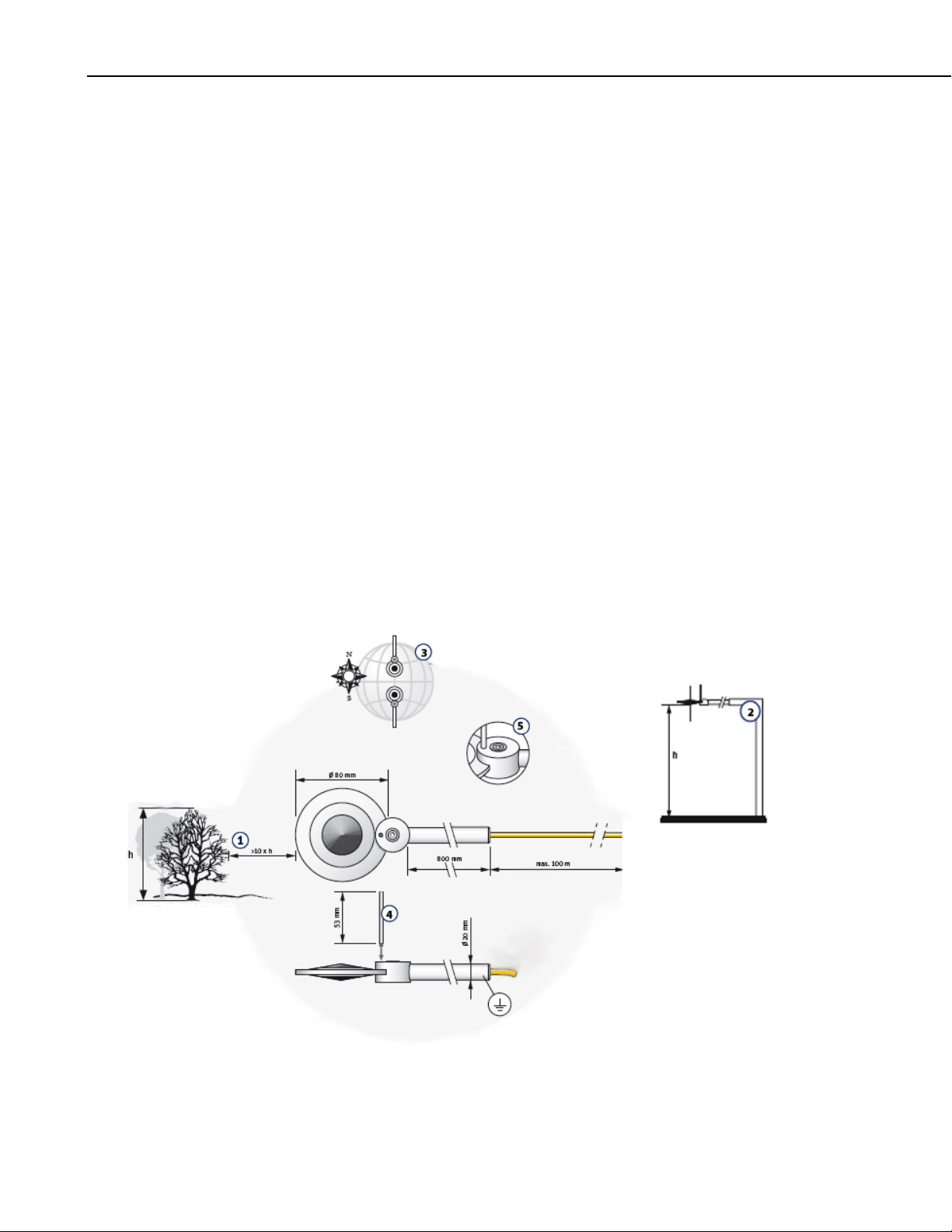
1. Mount the sensor so that no shadow will be cast on it at any time of day
from obstructions such as trees, buildings, the mast, or structure on which
it is mounted (1 in FIGURE 4-1).
2. To avoid shading effects and to promote spatial averaging, the NR-LITE2
should be mounted at least 1.5 m above the ground surface. It is
recommended that the NR-LITE2 be mounted to a separate vertical pipe at
least 25 ft from any other mounting structures (2 in FIGURE 4-1).
3. Orient the sensor towards the nearest pole to avoid potential problems
from shading (3 in FIGURE 4-1).
2
FIGURE 4-1. Siting and mounting diagram for the NR-LITE2
Page 9

4.2 Mounting
NR-LITE2 Net Radiometer
The mounting bracket kit, pn 26120, is used to mount the NR-LITE2 directly
to a vertical pipe, or to a CM202, CM204, or CM206 crossarm. Mount the
sensor as follows:
1. Screw in the bird repellent stick, which is shipped with the calibration
documentation (4 in FIGURE 4-1).
2. Attach the 26120 mounting bracket to the vertical mounting pipe, or
CM200-series crossarm using the provided U-bolt (FIGURE 4-2).
3. Insert the sensor’s support arm into the mounting block of the mounting
bracket kit. Make sure the sensor points in the direction of the arrows that
appear after the word SENSOR on top of the bracket (FIGURE 4-2).
4. Perform a coarse leveling of the sensor using the sensor’s bubble level (5
in FIGURE 4-1).
5. Tighten the four screws on top of the mounting bracket to properly secure
the support arm so that it does not rotate (FIGURE 4-2).
CAUTION
Do not attempt to rotate the instrument using the sensor
head or you may damage the sensor — use the support
arm only.
6. Perform the fine leveling using the two spring-loaded leveling screws—
one on the front and the other on the back of the bracket (FIGURE 4-2).
7. Route the sensor cable to the instrument enclosure.
8. Use cable ties to secure the cable to the vertical pipe or crossarm and
tripod/tower.
3
Page 10

NR-LITE2 Net Radiometer
Support Arm
26120
Pole
26120
FIGURE 4-2. Mounting the NR-LITE2 onto a pole (top) and
crossarm (bottom) via the 26120 Mounting Kit
Support Arm
Crossarm
4.3 Use SCWin to Program Datalogger and Generate Wiring Diagram
4
The simplest method for programming the datalogger to measure the NRLITE2 is to use Campbell Scientific’s SCWin Program Generator.
Page 11

NR-LITE2 Net Radiometer
NOTE
The SCWin example provided here is for no wind speed
correction. SCWin also supports dynamic wind speed
correction; refer to the SCWin help for more information.
1. Open Short Cut and click on New Program.
2. Select the datalogger and enter the scan interval.
5
Page 12

NR-LITE2 Net Radiometer
3. Select NR-LITE2 Net Radiometer (no wind speed correction), and
select the right arrow (in center of screen) to add it to the list of sensors to
be measured, and then select Next.
4. Define the name of the public variable and enter the calibration factor.
The public variable defaults to NR_Wm2. The calibration factor is unique
to each sensor. This value is provided on the certification of calibration
that is shipped with your sensor. After entering the information, click on
OK, and then select Next.
6
Page 13

NR-LITE2 Net Radiometer
5. Choose the outputs and then select Finish.
6. In the Save As window, enter an appropriate file name and select Save.
7. In the Confirm window, click Yes to download the program to the
datalogger.
8. Click on Wiring Diagram and wire according to the wiring diagram.
7
Page 14

NR-LITE2 Net Radiometer
5. Overview
The NR-LITE2 is used for measuring solar and far infrared radiation balance.
This balance is known as the net (total) radiation. Its upwards facing sensor
measures the solar energy and far infrared energy that is received from the
entire hemisphere (180° field of view). Its downwards facing sensor measures
the energy received from the surface of the soil. The two readings are
automatically subtracted and the result converted to a single output signal.
This output represents the net radiation (which can be interpreted as meaning
the radiative energy that is seen at the surface) and is expressed in Watts per
square meter (W m
The NR-LITE2 is designed for continuous outside use. The sensor surfaces are
coated with PTFE. This ensures sensor stability, long life, and easy
maintenance compared to the more usual radiometers fitted with plastic domes.
However, it does have some disadvantages, particularly a higher sensitivity to
wind speed with a subsequent lessening of accuracy. It is, though, possible to
correct for the wind speed sensitivity if the sensor is installed in a system
where wind speed is also being measured.
Although net radiometers are usually used in meteorology to measure radiation
balance, the NR-LITE2 can also be used to measure indoor climate radiative
stress.
-2
).
The NR-LITE2 is manufactured by Kipp & Zonen, but cabled for use with
Campbell Scientific dataloggers. Its cable can terminate in:
• Pigtails that connect directly to a Campbell Scientific datalogger
(cable termination option –PT).
• Connector that attaches to a prewired enclosure (cable termination
option ─PW).
5.1 Electrical Properties
The thermopile consists of a number of thermocouples connected in series,
essentially providing a highly sensitive differential temperature sensor. The
thermopile generates a voltage output — the sensor itself is passive, and so no
power supply is required.
The upwards and downwards facing sensor surfaces are connected to the upper
and lower thermopile junctions respectively, allowing the sensor to measure
the differential temperature (FIGURE 5-1). This temperature differential can
be measured to a high accuracy (in the order of 0.001 degrees), and is
proportional to the net radiation.
The thermopile determines the electrical characteristics of the instrument. Both
upper and lower facing sensors have a field of view of 180 degrees, and their
angular characteristics conform closely to the cosine response (see following
sections).
8
The electrical sensitivity for the thermopile changes with temperature, and no
nominal sensitivity value is available.
Page 15

FIGURE 5-1. Electrical circuit for the NR-LITE2 Net Radiometer
5.2 Spectral Properties
NR-LITE2 Net Radiometer
The upwards facing sensor is calibrated for solar radiation wavelengths. The
following assumptions are made:
• The downwards facing sensor has the same sensitivity. However, since
the two sensors may not be perfectly symmetrical, this assumption may
not always be true, but differences are small.
• The NR-LITE2’s sensitivity is the same for both solar and infrared
radiation.
5.3 Directional/Cosine Response
The measurement of the radiation falling on a surface (also known as
irradiance or radiative flux) is based on two assumptions:
1. The sensor surface is spectrally black — that it absorbs all radiation from
all wavelengths (Section 5.2, Spectral Properties).
2. That it has a true field of view of 180°.
These two properties, taken together, with which the net radiometer needs to
comply, are generally known as the cosine response.
A perfect cosine response will show maximum sensitivity at an angle of
incidence of zero degrees (perpendicular to the sensor surface) and zero
sensitivity at an angle of incidence of 90 degrees (radiation passing over the
sensor surface). At any angle between 0 and 90 degrees the sensitivity should
be proportional to the cosine of the angle of incidence.
FIGURE 5-2 shows the behavior of a typical net radiometer. The vertical axis
shows the deviation from ideal behavior, expressed in percentage deviation
from the ideal value.
9
Page 16

NR-LITE2 Net Radiometer
Error
Angle of Incidence
FIGURE 5-2. Cosine response of a typical net radiometer
5.4 Sensitivity to Wind Speed
The calibration of the NR-LITE2 is carried out at zero wind speed. At any
other wind speed, the sensitivity will decrease. It has been shown that this
decrease in sensitivity is less than 1% of reading per meter per second wind
speed, and the effect is essentially independent of the radiation level.
Net radiation readings can be corrected for wind speed sensitivity using the
following equation, which was developed by Jerry Brotzge at the Oklahoma
Climate Survey:
Wind Sensitivity equation for the NR-LITE2:
Rn,cor = Rn,obs U < 5 m s
Rn,cor = Rn,obs ∗ (1.0 + A × (U ─ 5.0)) U > 5 m s
Where,
Rn,cor = Net radiation corrected for wind speed
Rn,obs = Net radiation not corrected for wind speed
U = Horizontal wind speed in m s
A = empirical constant derived from data = 0.021286
-1
-1
-1
10
FIGURE 5-3 provides scatter plots showing the wind sensitivity for both the
NR-LITE2 and CNR1 net radiometer models.
Page 17

NR-LITE2 Net Radiometer
Differences between the NR-Lite and CNR1 as a function of wind speed for
daytime conditions during 7 May ─ 6 June, 1998. (a) No correction. (b) Eq. (4)
applied as a correction.
FIGURE 5-3. NR-LITE2 wind sensitivity
6. Specifications
Features:
Compatible dataloggers: CR800
CR850
CR1000
CR3000
CR5000
CR9000(X)
CR7
CR500
CR510
CR10(X)
CR23X
• Compatible with most Campbell Scientific dataloggers
• Integrated bubble level ensures proper installation
• Includes rod that deters birds from roosting on the radiometer
• PTFE-coated absorbers are weather resistant without using a fragile
plastic dome
11
Page 18

NR-LITE2 Net Radiometer
k
6.1 Spectral
6.2 Directional
Spectral range: 0.2 to 100 μm
Detector type: Thermopile
Detector protection: PTFE coating
Detector profile: Conical
Directional error
(0° to 60°C at 1000 W m
Sensor asymmetry: ±5% typical, (±10% worst case)
6.3 Mechanical
Housing material: Anodized aluminum
Cable material: Polyurethane
Weight: 200 g
Cable length: 15 m (can be extended up to 100 m)
Physical dimensions (FIGURE 6-1)
Sensor: 8.0 cm (3.1 in) diameter
Support arm: 1.6 cm (0.6 in) diameter x 80 cm (31.5 in) L
Weight: 635 g (23 oz)
∅16 x 800 Support Arm
∅80
-2
): <30 W m-2
Bird repelling stic
12
Bubble level indicator
FIGURE 6-1. NR-LITE2’s components and dimensions (in millimeters)
6.4 Environmental
Working temperature: ─30° to +70°C
Temperature dependence: 0.12% per °C
Support arm
Adjustable mounting arm
Page 19

7. Operation
k
7.1 Wiring
NR-LITE2 Net Radiometer
The NR-LITE2 can be measured with a differential or single-ended channel on
the datalogger; a differential channel is recommended.
FIGURE 7-1 provides the NR-LITE2 wiring. Datalogger connections are
shown in TABLE 7-1 for differential measurements and TABLE 7-2 for
single-ended measurements.
Red Radiation Signal
Blue Signal Reference
FIGURE 7-1. NR-LITE2 to datalogger connections
TABLE 7-1. Datalogger Connections for Differential Measurement
Function
Radiation Signal Red Differential H Differential H Differential H
Signal Reference Blue Differential L Differential L Differential L
Jumper to AG
Shield Black G
Color
(User supplied jumper wire for differential measurement only)
Blac
Shield
CR10X,
CR510,
CR500
CR23X,
21X, CR7
CR800,
CR850,
CR1000,
CR3000,
CR5000,
CR9000(X)
13
Page 20

NR-LITE2 Net Radiometer
TABLE 7-2. Datalogger Connections for Single-Ended Measurement
Function
Radiation Signal Red S.E. Channel S.E. Channel S.E. Channel
Signal Reference Blue AG
Shield Black G
Color
7.2 Datalogger Programming
NOTE
This section is for users who write their own datalogger
programs. A datalogger program to measure this sensor can be
generated using Campbell Scientific’s Short Cut Program
Builder Software. You only need to read the calibration portion
of this section if using Short Cut.
The NR-LITE2 outputs a low-level voltage ranging from 0 to a maximum of
about 15 mV. A differential voltage measurement (VoltDiff() in CRBasic or
instruction Volt (Diff) (P2) in Edlog) is recommended because it has better
noise rejection than a single-ended measurement. If a differential channel is
not available, a single-ended measurement (VoltSE() in CRBasic or instruction
Volt (SE) (P1) in Edlog) can be used. The acceptability of a single-ended
measurement can be determined by simply comparing the results of singleended and differential measurements made under the same conditions.
CR10X,
CR510,
CR500
CR23X,
21X, CR7
CR800,
CR850,
CR1000,
CR3000,
CR5000,
CR9000(X)
14
7.2.1 Input Range and Integration
Normally the 15 mV range for the 21X or CR7, the 25 mV range for the
CR800, CR850, CR1000, CR10(X), or CR500/CR510, and the 50 mV range
for the CR3000, CR5000, CR9000X, or CR23X are suitable.
The slow or 60 Hz rejection integration gives a more noise-free reading. A fast
integration takes less power and allows for faster throughput.
7.2.2 Calibration Factor
Each NR-LITE2 is provided with a Certificate of Calibration by the
manufacturer which shows the sensor serial number and a sensitivity or
calibration factor. This calibration factor, after conversion, is used in the
datalogger program. Always cross check to ensure that the serial number of
your NR-LITE2 and the number on the calibration certificate are identical.
The serial number and sensitivity are also shown on a small label attached to
the connecting arm near the head of the sensor itself.
The calibration factor included on the Certificate of Calibration is in units of
µV/(W m
multiplier parameter in the datalogger program. To convert the units, divide
-2
), which needs to be converted to units of (W m-2)/mV for the
Page 21

NR-LITE2 Net Radiometer
the calibration factor into 1000. For example, if the calibration factor is 15.8
µV/(W m
1000/15.8 = 63.29 (W m
-2
), the multiplier is:
-2
)/mV
7.2.3 Example Programs
7.2.3.1 CR3000 Example Program without Wind Speed Correction
Shown below is an example program written for the CR3000 datalogger.
TABLE 7-3 provides the wiring for the example program. In this example, the
datalogger measures the output from the sensor every 5 seconds and outputs
the average net radiation every hour. The calibration factor used will only
apply for one specific sensor. A new value will need to be calculated for every
different sensor based on the Certificate of Calibration for that sensor (Section
7.2.2, Calibration Factor).
TABLE 7-3. Wiring for CR3000 Example
Color Function CR3000 Channels
Red Radiation Signal 1H
Blue Signal Reference 1L
Jumpered to
Black Shield
'CR3000
'Declare Variables and Units
Public BattV
Public NR_Wm2
Units BattV=Volts
Units NR_Wm2=W/meter^2
'Define Data Tables
DataTable(Table1,True,-1)
DataInterval(0,60,Min,10)
Average(1,NR_Wm2,FP2,False)
EndTable
DataTable(Table2,True,-1)
DataInterval(0,1440,Min,10)
Minimum(1,BattV,FP2,False,False)
EndTable
'Main Program
BeginProg
Scan(5,Sec,1,0)
'Default Datalogger Battery Voltage measurement BattV
Battery(BattV)
'NR-LITE2 Net Radiometer (no wind speed correction) measurement NR_Wm2
VoltDiff(NR_Wm2,1,mV50,1,True,0,_60Hz,100,0)
'Call Data Tables and Store Data
CallTable(Table1)
CallTable(Table2)
NextScan
EndProg
15
Page 22

NR-LITE2 Net Radiometer
7.2.3.2 CR1000 Example Program with Wind Speed Correction
Shown below is an example program written for the CR1000 datalogger.
TABLE 7-4 provides the wiring for the example program. Besides measuring
the NR-LITE2, the program also measures wind speed and applies the
correction factor as described in Section 5.4, Sensitivity to Wind Speed.
Average net radiation and wind speed are output every hour.
TABLE 7-4. Wiring for CR1000 Example
Color Function CR1000 Channels
Red Radiation Signal 2H
Blue Signal Reference 2L
Jumpered to
Black Shield
'CR1000
'Declare Variables and Units
Dim WindCor_7
Public BattV
Public WS_ms
Public WindDir
Public NR_Wm2
Public CNR_Wm2
Units BattV=Volts
Units WS_ms=meters/second
Units WindDir=Degrees
Units NR_Wm2=W/m^2
Units CNR_Wm2=Watts/meter^2
'Define Data Tables
DataTable(Table1,True,-1)
DataInterval(0,60,Min,10)
Average(1,WS_ms,FP2,False)
Sample(1,WindDir,FP2)
Average(1,NR_Wm2,FP2,False)
Average(1,CNR_Wm2,FP2,False)
EndTable
DataTable(Table2,True,-1)
DataInterval(0,1440,Min,10)
Minimum(1,BattV,FP2,False,False)
EndTable
'Main Program
BeginProg
Scan(5,Sec,1,0)
'Default Datalogger Battery Voltage measurement BattV
Battery(BattV)
'05103 Wind Speed & Direction Sensor measurements WS_ms and WindDir
PulseCount(WS_ms,1,1,1,1,0.098,0)
BrHalf(WindDir,1,mV2500,1,1,1,2500,True,0,_60Hz,355,0)
If WindDir>=360 Then WindDir=0
'NR-LITE2 Net Radiometer (dynamic wind speed correction)
'measurement NR_Wm2 and CNR_Wm2
16
Page 23

NR-LITE2 Net Radiometer
VoltDiff(NR_Wm2,1,mv25,2,True,0,_60Hz,100,0)
If WS_ms>=5 Then
CNR_Wm2=NR_Wm2*(1+0.021286*(WS_ms-5))
Else
CNR_Wm2=NR_Wm2
EndIf
'Call Data Tables and Store Data
CallTable(Table1)
CallTable(Table2)
NextScan
EndProg
7.2.3.3 CR10(X) Example Program without Wind Speed Correction
Shown below is an example program written for the CR10(X) datalogger.
TABLE 7-5 provides the wiring for the example program. In this example, the
datalogger measures the output from the sensor every 60 seconds and outputs
the average net radiation every hour.
The calibration factor used will only apply for one specific sensor. A new
value will need to be calculated for every different sensor based on the
Certificate of Calibration for that sensor (Section 7.2.2, Calibration Factor).
TABLE 7-5. Wiring for CR10X Example
(without Wind Correction)
Color Function CR10X Channels
Red Radiation Signal 1H
Blue Signal Reference 1L
Jumpered to AG
Black Shield G
;{CR10X}
;
*Table 1 Program
01: 60 Execution Interval (seconds)
1: Volt (DIFF) (P2)
1: 1 Reps
2: 3** 25 mV Slow Range ;range code for CR10(X) datalogger
3: 1* DIFF Channel
4: 1* Loc [ Net_rad ]
5: 63.29 Mult ;Multiplier for specific sensor
6: 0.0 Offset ;in units of (W m-2)/mV (see above)
2: If time is (P92)
1: 0 Minutes (Seconds --) into a
2: 60 Interval (same units as above)
3: 10 Set Output Flag High (Flag 0)
3: Real Time (P77)
1: 110 Day,Hour/Minute (midnight = 0000)
4: Average (P71)
1: 1 Reps
2: 1 Loc [ Net_rad ]
17
Page 24

NR-LITE2 Net Radiometer
7.2.3.4 CR10X Example Program with Wind Speed Correction
;{CR10X}
;
*Table 1 Program
01: 60 Execution Interval (seconds)
;measure 05103 wind speed
1: Pulse (P3)
1: 1 Reps
2: 1 Pulse Channel 1
3: 21 Low Level AC, Output Hz
4: 1 Loc [ Wspd_m_s ]
5: .0980 Mult
6: 0 Offset
;measure NR-LITE2 net radiation
2: Volt (SE) (P1)
1: 1 Reps
2: 3** 25 mV Slow Range
3: 1* SE Channel
4: 2* Loc [ Rn_obs ]
5: 63.29 Mult ;Multiplier for specific sensor
6: 0 Offset ;in units of (W m-2)/mV (see above)
;apply wind speed correction factor
;Rn,cor = Rn,obs*(1.0+0.021286*(U-5.0)) when U > 5 m/s
3: If (X<=>F) (P89)
1: 1 X Loc [ Wspd_m_s ]
2: 3 >=
3: 5 F
4: 30 Then Do
This example measures the NR-LITE2 using a single-ended input and
instruction Volt (SE) (P1). The program also measures wind speed and applies
the correction factor as described in Section 5.4, Sensitivity to Wind Speed.
Average net radiation and wind speed are output every hour. TABLE 7-6
provides the wiring for this example program.
TABLE 7-6. Wiring for CR10X Example
(with Wind Correction)
Color Function CR10X Channels
Red Radiation Signal S.E. Channel 1
Blue Signal Reference AG
Black Shield G
18
Page 25

4: Z=X+F (P34)
1: 1 X Loc [ Wspd_m_s ]
2: -5 F
3: 24 Z Loc [ scratch_1 ]
5: Z=X*F (P37)
1: 24 X Loc [ scratch_1 ]
2: .021286 F
3: 25 Z Loc [ scratch_2 ]
6: Z=X+F (P34)
1: 25 X Loc [ scratch_2 ]
2: 1 F
3: 26 Z Loc [ scratch_3 ]
7: Z=X*Y (P36)
1: 26 X Loc [ scratch_3 ]
2: 2 Y Loc [ Rn_obs ]
3: 3 Z Loc [ Rn_cor ]
8: Else (P94)
9: Z=X (P31)
1: 2 X Loc [ Rn_obs ]
2: 3 Z Loc [ Rn_cor ]
10: End (P95)
11: If time is (P92)
1: 0 Minutes (Seconds --) into a
2: 60 Interval (same units as above)
3: 10 Set Output Flag High (Flag 0)
12: Real Time (P77)
1: 1220 Year,Day,Hour/Minute (midnight = 2400)
13: Average (P71)
1: 1 Reps
2: 3 Loc [ Rn_cor ]
14: Average (P71)
1: 1 Reps
2: 1 Loc [ Wspd_m_s ]
NR-LITE2 Net Radiometer
* Proper entries will vary with program and input channel assignments.
** 25 mV range for CR10(X) and CR510, the 50 mV range for CR23X, and the 15 mV range for
21X and CR7.
19
Page 26

NR-LITE2 Net Radiometer
8. Maintenance
The radiometer is an ‘all weather’ instrument and is very stable, but should be
handled with care. It requires little periodic maintenance, apart from cleaning
the sensor surfaces carefully with a soft cloth using water or alcohol.
The NR-LITE2 should be recalibrated every two years. An RMA number is
required before returning the sensor for recalibration; refer to the Assistance
section in the beginning of this manual for more information.
9. Troubleshooting
9.1 Checking Sensor Operation
To effectively check the instrument’s operation, you will need:
• NR-LITE2
• Voltmeter, range 0 to 50 mV, with an input impedance greater than
• Light source
• Table or bench
5000 Ohms
Position the radiometer so that its downward facing sensor is about 10 mm (0.4
in) above a flat surface (table or bench), and the upwards facing sensor is
facing the light source (lamp). Do not touch the sensor head itself, as this will
introduce thermal shocks. Hold the instrument only by its mounting arm at all
times.
Follow the procedure outlined below:
1. Connect the NR-LITE2 wires to the voltmeter. Connect the red wire to the
positive lead and the blue wire to the negative lead.
2. Select the most sensitive range on the voltmeter.
3. With the lamp switched off, read the sensor output signal — allow a
minute or so for the signal to fully stabilize.
4. Switch on the lamp. The sensor should now produce a higher positive
reading.
5. Turn the lamp off again, when the signal should slowly return to its
original level, proving the sensor’s sensitivity to light.
6. Turn the sensor upside down. The signal value should reverse in sign; a
+10 mV signal should become a ─10 mV signal. Don’t worry if the two
values are not exactly the same (up to 10% difference) as the sensor
profiles can vary. After completing this test, return the sensor to its
original orientation and let it stabilize.
20
7. Put your hand over the upper sensor. Assuming that your hand is at a
higher temperature than the sensor, the positive reading should increase.
Page 27

NR-LITE2 Net Radiometer
Conversely, if the sensor is warmer than your hand, the reading will
decrease.
8. Check the radiometer’s sensitivity to thermal shocks by touching the edge
of the sensor (the blank metal) with your hand for some seconds. The
resultant shock will result in a signal drift, or a zero offset that will take
some time to settle back to zero.
9. Adjust the range of the voltmeter so that the expected full-scale output of
the radiometer is about the same as the range of the voltmeter. A
(theoretical) way to calculate the maximum expected output for normal
meteorological applications is shown below:
-2
Max. expected radiation +1500 W m
Min. radiation –200 W m
-2
Sensitivity of the net radiometer 10 μV/(W m
Expected output range of the radiometer is (1500 + 200) × 10 =
1700 × 10 = 17.0 mV or 0.017 V.
9.2 Radiometer Produces No Apparent Output
-2
)
If your net radiometer does not appear to be working at all, do the following
checks:
1. Check the instrument’s sensitivity to radiation, following the procedure
shown in Section 9.1, Checking Sensor Operation.
2. If this appears to produce no results, measure the impedance of the sensor
across the red and blue wires. The impedance reading should be close to
2.3Ω. If it is virtually zero, a short circuit is indicated. If it is ‘infinite’,
the thermopile is blown.
9.3 Readings Are Not As Expected
1. Under full sunlight, the expected radiation value is about 1000 W m-2.
Under lamps it may be greater. For indoor climate studies, smaller values
are to be expected unless solar radiation is present. A typical value for a
room when facing a wall and a relatively cold window is 50 W m
2. Are you using the correct calibration factor? Note that this factor is unique
for each individual sensor as noted on the calibration certificate provided
with that sensor. Did you convert the factor to the correct value for the
datalogger program? (Section 7.2, Datalogger Programming.)
3. Check the datalogger program for errors.
-2
.
If you cannot resolve your problems, please contact Campbell Scientific for
further advice.
21
Page 28

NR-LITE2 Net Radiometer
22
Page 29

Page 30

Campbell Scientific Companies
Campbell Scientific, Inc. (CSI)
815 West 1800 North
Logan, Utah 84321
UNITED STATES
www.campbellsci.com • info@campbellsci.com
Campbell Scientific Africa Pty. Ltd. (CSAf)
PO Box 2450
Somerset West 7129
SOUTH AFRICA
www.csafrica.co.za • cleroux@csafrica.co.za
Campbell Scientific Australia Pty. Ltd. (CSA)
PO Box 8108
Garbutt Post Shop QLD 4814
AUSTRALIA
www.campbellsci.com.au • info@campbellsci.com.au
Campbell Scientific do Brasil Ltda. (CSB)
Rua Apinagés, nbr. 2018 ─ Perdizes
CEP: 01258-00 ─ São Paulo ─ SP
BRASIL
www.campbellsci.com.br • vendas@campbellsci.com.br
Campbell Scientific Canada Corp. (CSC)
11564 - 149th Street NW
Edmonton, Alberta T5M 1W7
CANADA
www.campbellsci.ca • dataloggers@campbellsci.ca
Campbell Scientific Centro Caribe S.A. (CSCC)
300 N Cementerio, Edificio Breller
Santo Domingo, Heredia 40305
COSTA RICA
www.campbellsci.cc • info@campbellsci.cc
Campbell Scientific Ltd. (CSL)
Campbell Park
80 Hathern Road
Shepshed, Loughborough LE12 9GX
UNITED KINGDOM
www.campbellsci.co.uk • sales@campbellsci.co.uk
Campbell Scientific Ltd. (France)
3 Avenue de la Division Leclerc
92160 ANTONY
FRANCE
www.campbellsci.fr • info@campbellsci.fr
Campbell Scientific Spain, S. L.
Avda. Pompeu Fabra 7-9, local 1
08024 Barcelona
SPAIN
www.campbellsci.es • info@campbellsci.es
Please visit www.campbellsci.com to obtain contact information for your local US or international representative.
 Loading...