

Page 1

NR01 Four-Component
Net Radiation Sensor
Revision: 8/11
Copyright © 2008-2011
Campbell Scientific, Inc.
Page 2

Warranty and Assistance
PRODUCTS MANUFACTURED BY CAMPBELL SCIENTIFIC, INC. are
warranted by Campbell Scientific, Inc. (“Campbell”) to be free from defects in
materials and workmanship under normal use and service for twelve (12) months
from date of shipment unless otherwise specified on the corresponding Campbell
invoice. Batteries, fine-wire thermocouples, desiccant, and other consumables have
no warranty. Campbell's obligation under this warranty is limited to repairing or
replacing (at Campbell's option) defective products, which shall be the sole and
exclusive remedy under this warranty. The customer shall assume all costs of
removing, reinstalling, and shipping defective products to Campbell. Campbell
will return such products by surface carrier prepaid within the continental United
States of America. To all other locations, Campbell will return such products best
way CIP (Port of Entry) INCOTERM
apply to any Campbell products which have been subjected to modification,
misuse, neglect, improper service, accidents of nature, or shipping damage. This
warranty is in lieu of all other warranties, expressed or implied. The warranty for
installation services performed by Campbell such as programming to customer
specifications, electrical connections to products manufactured by Campbell, and
product specific training, is part of Campbell’s product warranty. CAMPBELL
EXPRESSLY DISCLAIMS AND EXCLUDES ANY IMPLIED WARRANTIES
OF MERCHANTABILITY OR FITNESS FOR A PARTICULAR PURPOSE.
Campbell is not liable for any special, indirect, incidental, and/or consequential
damages.
Products may not be returned without prior authorization. The following contact
information is for US and International customers residing in countries served by
Campbell Scientific, Inc. directly. Affiliate companies handle repairs for customers
within their territories. Please visit www.campbellsci.com to determine which
Campbell Scientific company serves your country.
®
2010, prepaid. This warranty shall not
To obtain a Returned Materials Authorization (RMA), contact Campbell Scientific,
Inc., phone (435) 753-2342. After an applications engineer determines the nature
of the problem, an RMA number will be issued. Please write this number clearly
on the outside of the shipping container. Campbell Scientific's shipping address is:
CAMPBELL SCIENTIFIC, INC.
RMA#_____
815 West 1800 North
Logan, Utah 84321-1784
For all returns, the customer must fill out a “Declaration of Hazardous Material and
Decontamination” form and comply with the requirements specified in it. The form
is available from our website at
must be either emailed to repair@campbellsci.com
Campbell Scientific will not process any returns until we receive this form. If the
form is not received within three days of product receipt or is incomplete, the
product will be returned to the customer at the customer’s expense. Campbell
Scientific reserves the right to refuse service on products that were exposed to
contaminants that may cause health or safety concerns for our employees.
www.campbellsci.com/repair
or faxed to 435-750-9579.
. A completed form
Page 3

NR01 Table of Contents
PDF viewers note: These page numbers refer to the printed version of this document. Use
the Adobe Acrobat® bookmarks tab for links to specific sections.
1. Introduction..................................................................1
2. Measurement Principle ...............................................3
2.1 General......................................................................................................3
2.2 NR01 Construction ...................................................................................4
2.3 Pyranometers ............................................................................................5
2.4 Pyrgeometers ............................................................................................6
2.5 Expected Measurement Results................................................................8
2.6 Heating....................................................................................................10
2.7 Data Quality Assurance ..........................................................................10
3. Specifications of NR01..............................................10
3.1 NR01 General Specifications .................................................................11
3.2 SR01 Pyranometer Specifications ..........................................................12
3.3 IR01 Pyrgeometer Specifications ...........................................................13
3.4 Dimensions .............................................................................................14
4. Installation..................................................................14
4.1 Installation ..............................................................................................14
4.2 Electrical Connections ............................................................................16
4.3 Connecting the Sensor to Campbell Scientific Dataloggers ...................17
4.3.1 Connecting and Using the Heater .................................................19
4.4 Installation of the Radiation Shields.......................................................20
4.5 Instrument-Inversion-Test ......................................................................20
5. Datalogger Programming.......................................... 20
5.1 Calibration Factors..................................................................................21
5.2 Example Programs..................................................................................22
5.2.1 Example 1, CR1000 Using Differential Channels ........................22
5.2.2 Example 2, CR3000/CR5000 Using Differential Channels
(no 4WPB100) ..........................................................................25
5.2.3 Example 3, CR23X Program Using Differential Channels...........27
5.2.4 Example 4, CR23X Program Using Single-Ended Channels .......31
6. Maintenance and Troubleshooting ..........................33
6.1 Maintenance............................................................................................33
6.2 Troubleshooting......................................................................................34
Appendix
A. CR3000 Program that Controls the Heater ........................................... A-1
i
Page 4

NR01 Table of Contents
Figures
Tables
1-1. Atmospheric Radiation as a Function of Wavelength ............................ 2
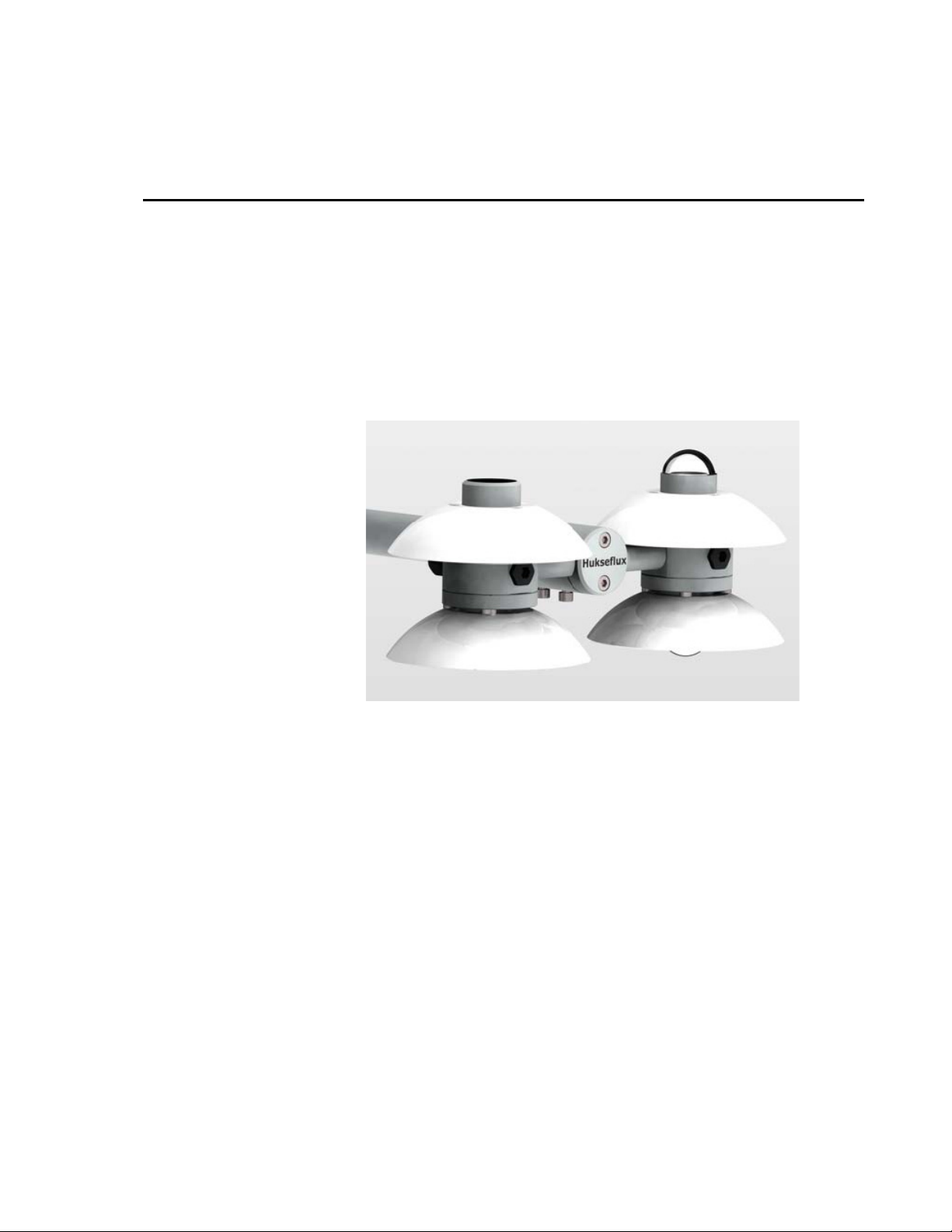
2.2-1. The NR01 Four-Component Net Radiation Sensor............................. 4
2.3-1. Spectral Response of the Pyranometer Compared to the Solar
Spectrum.......................................................................................... 5
2.4-1. Spectral Response of the Pyrgeometer Compared to the Atmospheric
LW Spectrum................................................................................... 7
3.4-1. Dimensions of the NR01 in mm ........................................................ 14
4.1-1. NR01 with Reducer (P/N 21271) and Mounting Arm....................... 15
4.4-1. Installation and Removal of Radiation Shields.................................. 20
5-1. 4WPB100 Module ................................................................................ 21
2.3-1. Main Measurement Errors in the SW Signal....................................... 6
2.4-2. Main Measurement Errors in the LW Signal....................................... 8
2.5-1. Average Global Radiation Values at the Earth Surface....................... 9
2.5-2. Expected SENSOR Outputs when Measuring with the NR01 ............ 9
3.1-1. General Specifications of the NR01 .................................................. 11
3.2-1. Specifications of SR01 ...................................................................... 12
3.3-1. Specifications of IR01 ....................................................................... 13
4.1-1. Recommendations for Installation of the NR01 ................................ 15
4.2-1. Internal Electrical Diagram of the NR01........................................... 17
4.3-1. Datalogger Connections for Differential Measurement,
when using a 4WPB100................................................................. 18
4.3-2. Datalogger Connections for Single-Ended Measurement,
when using a 4WPB100................................................................. 18
4.3-3. Pt-100 Temperature Sensor Connections to 4WPB100 and
Datalogger...................................................................................... 18
4.3-4. CR3000 and CR5000 Connections for Differential Measurement
and using the Current Excitation to Measure the PT100 Sensor ... 19
6.1-1. The NR01 Recommendations for Maintenance................................. 33
6.2-1. Troubleshooting for the NR01........................................................... 34
ii
Page 5
NR01 Four-Component Net Radiation Sensor
The NR01 is a four-component net radiation sensor that is used for scientific-grade energy
balance studies.
1. Introduction
The NR01 has separate measurements of solar (Short Wave or SW) and Far
Infra-Red (Long Wave or LW) radiation. It offers a professional solution to
the measurement of net radiation and its four main components. The NR01 is
robust and requires only limited maintenance.
Measurement of the separate components of the net radiation is useful because
it:
• Enhances accuracy by having separately calibrated instruments (similar
accuracy cannot be attained with sensors with single outputs or dual
outputs). Single-output or dual-output instruments will always suffer from
instrument asymmetry or from errors due to sensitivity differences for LW
and SW radiation.
• Provides more detailed information than sensors with single or dual
outputs (e.g., albedo of the ground, cloud condition).
• Allows more thorough quality assurance of the instrument data (compared
to sensors with single or dual outputs). Quality assurance with fourcomponent radiometers is done by analyzing trends in SW
signal, SW albedo, correlation of SW
and correlation LW
and surface temperature.
out
and LWin, SW night time signals,
in
absolute
in
1
Page 6
NR01 Four-Component Net Radiation Sensor
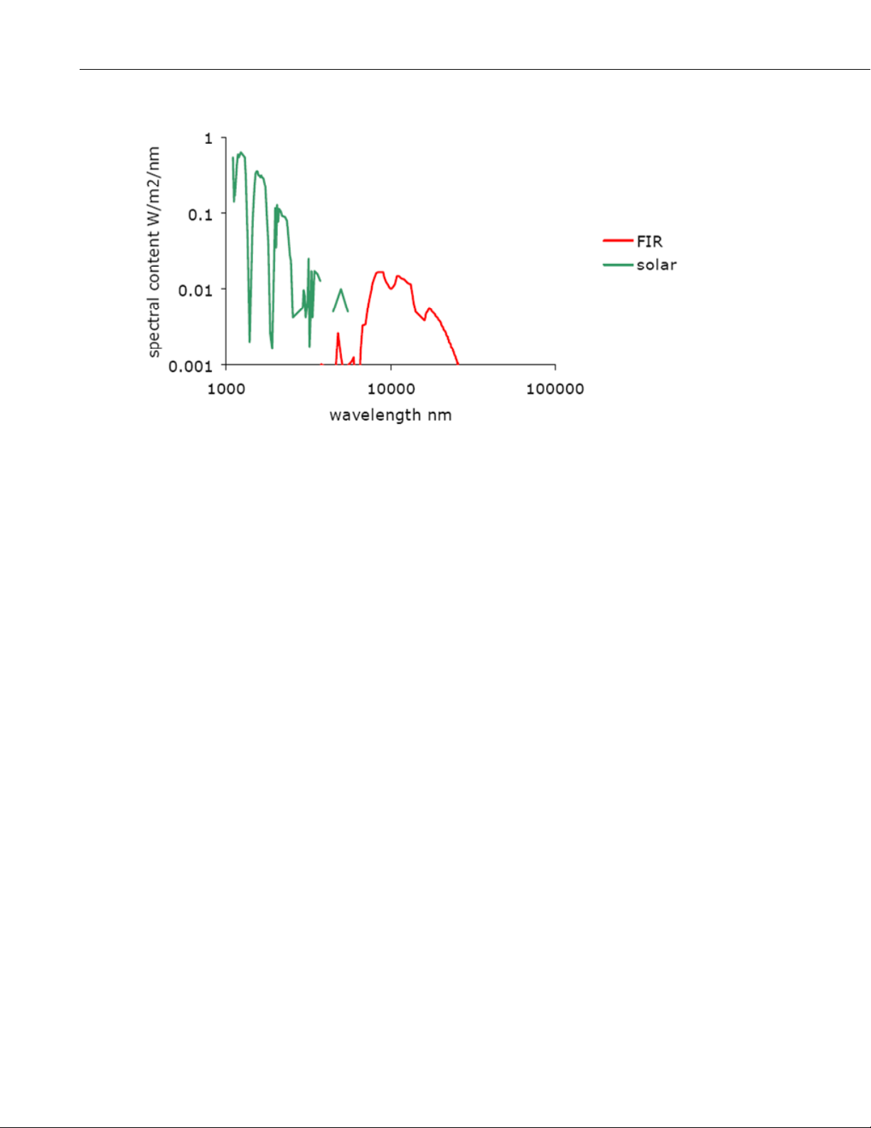
FIGURE 1-1. Atmospheric Radiation as a Function of Wavelength
LW or FIR radiation is mainly present in the 4500 to 50000 nm region, while SW or solar radiation is
mainly present in the 300 to 3000 nm region. The two are measured separately.
Major improvements of the NR01 relative to comparable instruments include
reduced weight, reduced solar offsets in the LW signal, ease of leveling
(because a 2-axis leveling assembly is built-in).
The NR01 serves to measure the four separate components of the surface
radiation balance. Working completely passive, using thermopile sensors, the
NR01 generates four small output voltages proportional to the incoming and
outgoing SW and LW fluxes; SW
solar radiation, LW
or infrared emitted by the sky and LW
in
or global solar radiation, SW
in
or reflected
out
or infrared
out
emitted by the ground surface.
From these also parameter like SW “albedo”, “sky temperature”, “(ground)
surface temperature” and off course “net-radiation” (net value of all SW and
LW fluxes) can be calculated.
The SW sensors are also called pyranometers (type SR01); the LW sensors are
called pyrgeometers (type IR01). For calculation of the sky and surface
temperature, a PT100 temperature sensor is included in the connection body of
the pyrgeometers. A heater is also included in the pyrgeometers’ connection
body to heat the pyrgeometers, which prevents the deposition of dew.
The NR01 requires leveling; a two-axis leveling facility is incorporated in the
design. See the chapter on installation.
Using the NR01 is easy. For readout one only needs four analog input
channels, and, only if sky and surface temperature are required, a way to
measure the PT100. If power is available, Campbell Scientific recommends
heating the pyrgeometers from sundown to sunset.
2
Page 7

NR01 Four-Component Net Radiation Sensor
The NR01 is supplied with four separate instrument sensitivities. As a brief
explanation, to calculate the radiation level, the sensor output voltage, U, must
be divided by the sensor sensitivity; a constant, E, that is supplied with each
individual instrument. For example:
Φ = SW
in
= U
pyrano, up
More information can be found in the chapter on instrument performance.
WARNING
The NR01 is a passive sensor, and does not need any
power. The NR01 pyrgeometer can, however, be
heated to prevent dew-deposition.
Putting more than 12 Volt across the NR01 sensor
wiring can permanently damage the sensor.
2. Measurement Principle
The following chapters explain the measurement principles of the NR01.
Pyranometers and pyrgeometers are treated in different paragraphs. The last
section is about expected measurement results.
2.1 General
In its most common application, the NR01 measures net-radiation. The four
components of net radiation are measured and the net radiation is calculated:
/ E
pyrano, up
NOTE
The temperature (T
) for the following formula is in Kelvin.
pyrgeo
If the temperature is measured in degrees Celsius, add 273.15 to
pyrgeo
out
= (U
in
out
net
net
= U
= (U
= U
= U
value.
pyrano, up
pyrano, down
pyrgeo, up
pyrgeo, down
pyrgeo, up
pyrano, up
+ LW
net
/ E
/ E
/ E
net
/ E
/ E
net
2.1-1
pyrano, up
pyrano, down
pyrgeo, up
/ E
pyrgeo, down
2.1-2
) + 5.67.10-8 (T
) + 5.67.10-8 (T
pyrgeo
4
)
)4 2.1-4
pyrgeo
the instrument temperature is cancelled:
pyrgeo, up
pyrano, up
- U
- U
pyrgeo, down
pyrano, down
/ E
/ E
pyrano, down
pyrgeo, down
2.1-5
2.1-6
2.1-7
the T
SWin = U
SW
LW
LW
NOTE: in the LW
LW
SW
NR = SW
Special parameters that could be deducted:
SW albedo = SW
/ SW
in
out
2.1-3
2.1-8
3
Page 8
NR01 Four-Component Net Radiation Sensor
NOTE
The following equations assume the temperature is in Kelvin.
Add 273.15 to equations 2.1-9 and 2.1-10 for temperature in
degree Celsius.
T
= (LW
surface
T
= (LW
sky
in
2.2 NR01 Construction
/5.67.10-8)
out
/5.67.10-8)
1/4
2.1-9
1/4
2.1-10
FIGURE 2.2-1. The NR01 Four-Component Net Radiation Sensor
(1) SW
(2) LW
solar radiation sensor or pyranometer,
in
Far Infrared radiation sensor or pyrgeometer
in
(3) radiation shield
(4) leveling assembly for x- and y axis, block plus bolts for x-axis
adjustment
(5) leveling assembly for x- and y axis, horizontal rod
(6) connection body containing the Pt100 temperature sensor, heater,
and hole for user-supplied temperature sensor (add cable gland M8)
(7) LW
Far Infrared radiation sensor or pyrgeometer
out
(8) leveling assembly for x- and y-axis, bolts for y-axis adjustment
(9) SW
solar radiation sensor or pyranometer
out
A level is located under the radiation screens.
4
Page 9
2.3 Pyranometers
A pyranometer should measure the solar or SW radiation flux from a field of
view of 180 degrees. The atmospheric SW radiation spectrum extends roughly
from 300 to 2800 nm. It follows that a pyranometer should cover that
spectrum with a spectral sensitivity that is as “flat” as possible.
For a flux measurement, it is required by definition that the response to “beam”
radiation varies with the cosine of the angle of incidence. For example, full
response occurs when the solar radiation hits the sensor perpendicularly
(normal to the surface, sun at zenith, 0 degrees angle of incidence); zero
response occurs when the sun is at the horizon (90 degrees angle of incidence,
90 degrees zenith angle), and half a response occurs at 60 degrees angle of
incidence. It follows from the definition that a pyranometer should have a socalled “directional response” or “cosine response” that is close to the ideal
cosine characteristic.
In order to attain the proper directional and spectral characteristics, a
pyranometer’s main components are:
1. Thermopile sensor with a black coating—absorbs all solar radiation,
NR01 Four-Component Net Radiation Sensor
provides a flat spectrum covering the 300 to 50000-nanometer range, and
has a near-perfect cosine response.
2. Glass dome—limits the spectral response from 300 to 2800 nanometers
(cutting off the part above 2800 nm) while preserving the 180 degrees
field of view. Another function of the dome is that it shields the
thermopile sensor from convection.
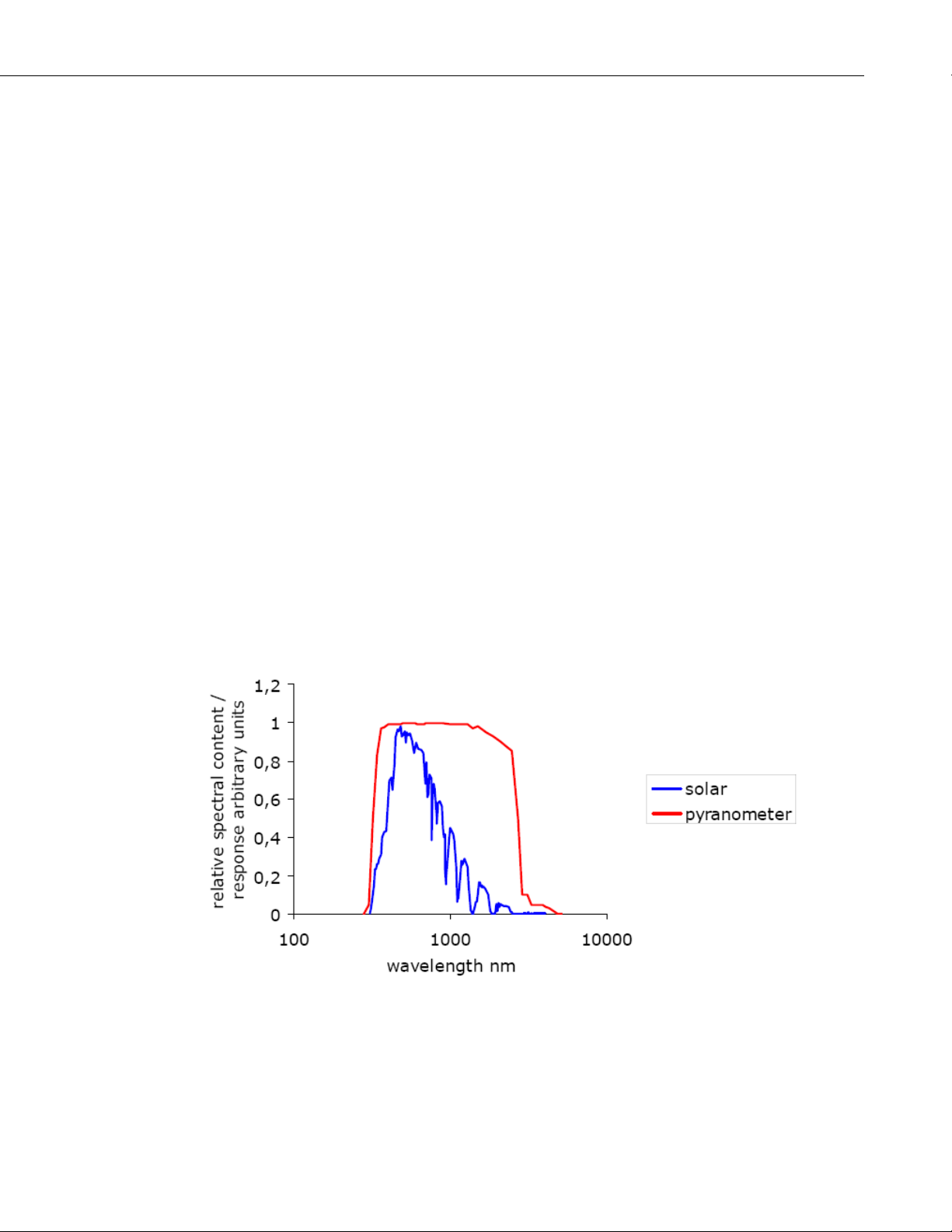
FIGURE 2.3-1. Spectral Response of the Pyranometer Compared to the Solar Spectrum
The pyranometer only cuts off a negligible part of the total solar spectrum.
5
Page 10

NR01 Four-Component Net Radiation Sensor
The black coating on the thermopile sensor absorbs the solar radiation. This
radiation is converted to heat. The heat flows through the sensor to the
pyranometer housing. The thermopile sensor generates a voltage output signal
that is proportional to the solar radiation.
SW
in
= U
pyrano, up
/ E
2.3-1
pyrano, up
In case of the NR01, the pyranometer is type SR01. This is a second-class
pyranometer according to the WMO and ISO classification system (ISO 9060).
The atmospheric solar radiation consists of two components—direct radiation
(in a beam from the sun) and diffuse radiation from the sky.
For down facing instruments, the earth surface reflects part of the solar
radiation, depending on the local surface properties. If there is direct radiation,
this often is the dominant source of energy. Because the solar position is
changing, this implies that for a pyranometer the directional response is quite
important.
Table 2.3-1 summarizes the main sources of measurement errors for the SR01.
The error in the directional response is caused by non-perfect optical properties
of the dome and coating. The infrared offset is produced when the low
temperature “sky” cools off the instrument dome. Because the LW radiation
balance between dome and sky is negative, a negative sensor offset occurs as
the dome cools.
TABLE 2.3-1. Main Measurement Errors in the SW Signal
Source Maximum Error
Directional response +/- 30 W/m2 on SW
+/- 15 W/m
2
on SW
in practice this level is
in
at 1000 W/m
in
2
SWin
Infrared offset - 15 W/m2 on SW
Temperature dependence +/- 5 % for the entire range
2.4 Pyrgeometers
A pyrgeometer should measure the far infrared or LW radiation flux from a
field of view of 180 degrees. The atmospheric LW radiation spectrum extends
roughly from 4500 to 50000 nm. The pyrgeometer should cover that spectrum
with a spectral sensitivity that is as “flat” as possible.
For a flux measurement, by definition, the response to “beam” radiation varies
with the cosine of the angle of incidence. For example, full response occurs
when the radiation hits the sensor perpendicularly (normal to the surface,
source at zenith, 0 degrees angle of incidence); zero response occurs when the
radiation comes from the horizon (90 degrees angle of incidence, 90 degrees
zenith angle), and half a response occurs at 60 degrees angle of incidence. It
follows from the definition that a pyrgeometer should have a so-called
“directional response” or “cosine response” that is close to the ideal cosine
characteristic.
at -200 W/m2 LW
in
net
6
Page 11
NR01 Four-Component Net Radiation Sensor
To attain the proper directional and spectral characteristics, a pyrgeometer’s
main components are:
1 Thermopile sensor with a black coating—absorbs all LW and SW
radiation, provides a flat spectrum covering the 300 to 50000 nanometer
range, and has a near-perfect cosine response.
2 Silicon window with solar blocking—limits the spectral response from
4500 to 50000 nanometers (cutting off the part below 4500 nm) while
preserving the 150 degrees field of view (not the ideal 180 degrees).
Another function of the window is that it shields the thermopile sensor
from convection.
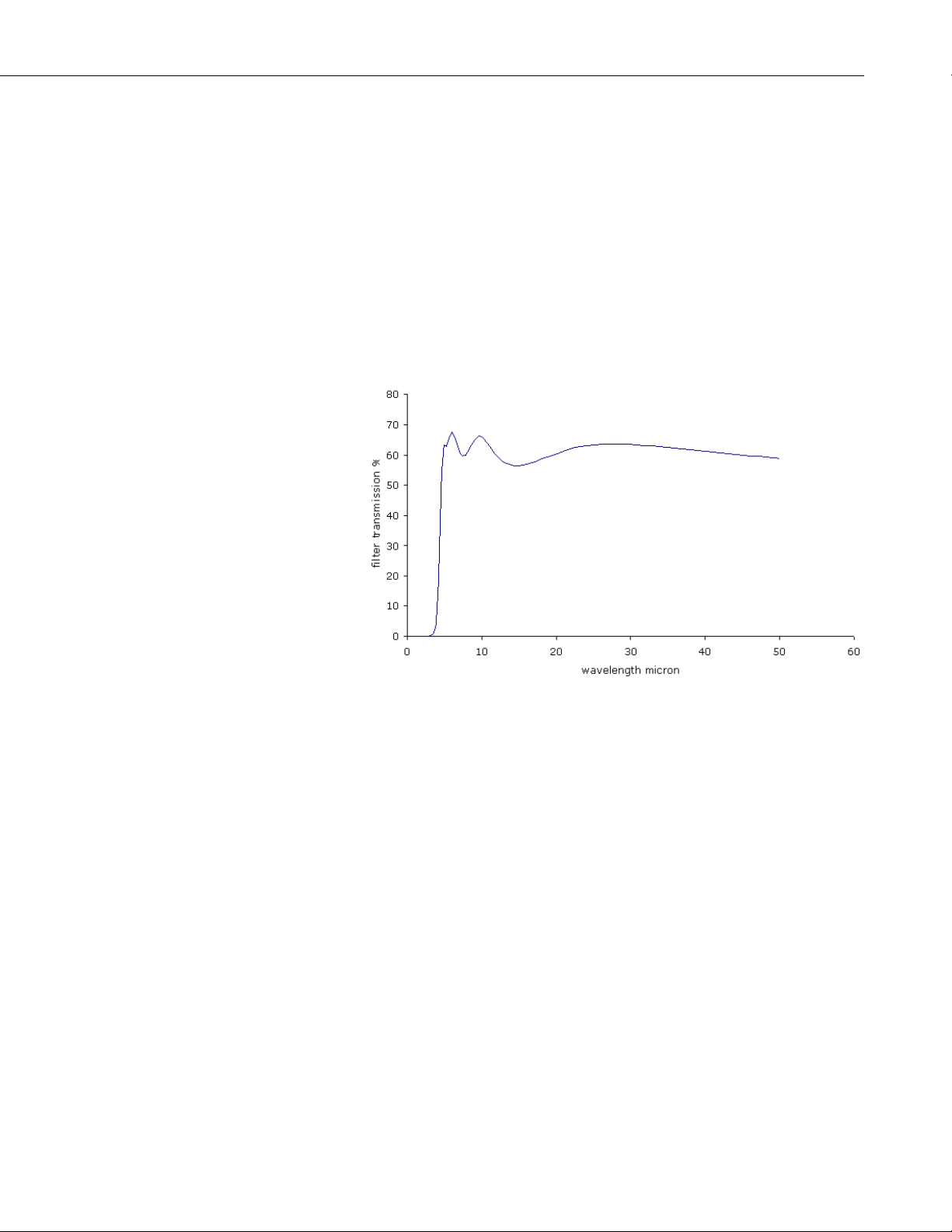
FIGURE 2.4-1. Spectral Response of the Pyrgeometer Compared to
the Atmospheric LW Spectrum
The black coating on the thermopile sensor absorbs the LW radiation. This
radiation is converted to heat. The heat flows through the sensor to the
housing. The thermopile sensor generates a voltage output signal that is
proportional to the LW radiation that is exchanged between sensor and source.
However, the sensor itself also irradiates LW radiation. This is according to
Plank’s law, so that the pyrgeometer thermopile signal is composed of the
incoming radiation minus the outgoing radiation. In order to estimate the
outgoing component, the pyrgeometer temperature is measured independently,
using a Pt100 or a user-supplied temperature sensor. Equation 2.4-1 calculates
the incoming LW radiation assuming T
LW
= (U
in
For LW
out
pyrgeo, up
/ E
) + 5.67.10-8 (T
pyrgeo, up
a similar formula is valid. The equations are the same for up- and
is in Kelvin:
pyrgeo
)4 2.4-1
pyrgeo
down facing instruments.
It is possible to calculate temperatures of the objects within the field of view of
the instrument, assuming these are uniform- temperature blackbodies (emission
7
Page 12

NR01 Four-Component Net Radiation Sensor
coefficient of 1). For example, equation 2.4-2 calculates, in Kelvin, the sky
temperature:
T
sky
= (LW
/5.67.10-8)
in
1/4
2.4-2
The NR01’s pyrgeometers are type IR01. Pyrgeometers are not classified by
the ISO or WMO.
The atmospheric LW
radiation essentially consists of two components:
in
1 Low temperature radiation from the universe, filtered by the atmosphere.
The atmosphere is transparent for this radiation in the so-called
atmospheric window (around 10 to 15 micrometer wavelength).
2 Higher temperature radiation emitted by atmospheric gasses.
Down facing instruments are presumably looking directly at the surface, which
behaves like a normal blackbody.
As a first approximation, the sky can, be seen as a cold temperature source
with its lowest temperatures at zenith and getting warmer at the horizon. The
uniformity of this LW source is much better than that in the solar (SW) range,
where the sun is a dominant and non-uniform contributor. This explains why a
pyrgeometer with 150 degrees field of view can perform a good measurement.
Table 2.4-2 summarizes the main measurement errors for the IR01. The error
in the directional response is caused by non-perfect field of view. The windowheating offset occurs when solar radiation heats up the instrument window,
producing a positive sensor offset.
TABLE 2.4-2. Main Measurement Errors in the LW Signal
Source Maximum Error
Directional response 8 W/m2 on LWin at -100 W/m2 LW
Window heating offset +15 W/m2 on LW
SW
in
Temperature
dependence
+/- 5 % for the entire range
2.5 Expected Measurement Results
The average energy balance at the earth surface strongly depends on the:
• Latitude (mostly for SW)
• Local surface properties (SW and LW)
• Local surface temperature (LW)
Table 2.5-1 summarizes the average global values. The average net radiation at
the earth surface is positive, and the remaining energy is used for convective
heat transport and evaporation.
net
at 1000 W/m2
in
8
Page 13

NR01 Four-Component Net Radiation Sensor
TABLE 2.5-1. Average Global Radiation Values
at the Earth Surface
Type SW in SW
SW
out
LW in LW
net
LW
out
Net
net
Units W/m2 W/m2 W/m2 W/m2 W/m2 W/m2 W/m2
Value 198 - 30 168 324* -390** -66 102
value assumes a sky temperature of 2ºC.
in
value assumes a surface temperature of 14ºC.
out
NOTE
* LW
** LW
The LW radiation values in Table 2.5-1 are corrected for sensor
temperature. The values in Table 2.5-2 are not corrected for
sensor temperature.
On a smaller timescale, the most important factors are:
• solar position
• cloud cover
The ambient air temperature is less important because cloud base temperature
tends to follow surface temperature.
TABLE 2.5-2. Expected SENSOR Outputs when Measuring with the NR01
D / N CD / CR
Ambient
air temp.
pyrgeo
#
down
pyrgeo
up#
pyrano
down
pyrano
up
T
T
sky
ground
°C W/m2 W/m2 W/m2 W/m2 °C °C
D CD +20 0 0 0-500 0-150 20 +20
D CD -20 0 0 0-500 0-150 -20 -20
D CR +20 -70** 0 0-1500 0-400 +1 +20
D CR -20 -70** 0 0-1500 0-400 -50 -20
N CD +20 0 0 0 0 +20 +20
N CD -20 0 0 0 0 -20 -20
N CR +20 -70* 0 0*** 0 1 +20
N CR -20 -70* 0 0*** 0 50 -20
The table makes a distinction between the day and night (D/N), cloudy and
clear (CD / CR) conditions, and high and low ambient air temperatures.
The instrument temperature is normally close to air temperature.
9
Page 14

NR01 Four-Component Net Radiation Sensor
#Outputs listed for both of the pyrgeometers are not compensated for sensor
temperature. For example, to correct for sensor temperature when the sensor
temperature is 14 ºC, you should add 385 W/m
The raw reading of the upward facing pyrgeometer will generally be close to
zero when the sensor temperature is close to the ground temperature. You
should expect small negative readings when the sensor is located above cooled
surfaces (e.g. water or transpiring vegetation) or small positive readings when
the surface is emitting heat (e.g. warm soil at night).
2
to the pyrgeometer signals.
* At night, dew deposition may affect the downward facing pyrgeometer’s
output. In that case, the signal may drop to 0 W/m
error of +100 W/m
avoid dew deposition.
** During the day, the window-heating offset may affect the downward facing
pyrgeometer’s output. This can produce a maximum error of +15 W/m
***At night, the infrared offset may affect the downward facing pyranometer’s
output. The maximum error of this offset is -25 W/m
2.6 Heating
A heater is located in the connection body of the pyrgeometers to prevent dew
deposits on the sensor that may occur at night. Because of the heater’s current
drain, Campbell Scientific recommends using the heater only when necessary.
A relay can turn the heater on when the solar radiation is less than 20 W/m
See Section 4.3.1.
2.7 Data Quality Assurance
To assure quality data, look for unrealistic values when analyzing:
• Trends in SW
• SW albedo
• Correlation of SW
• SW night time signals
• Correlation of relation LW
in
2
2
. Campbell Scientific recommends activating the heater to
absolute signal,
and LWin
in
and surface temperature
out
, producing a maximum
2
.
2
.
2
.
3. Specifications of NR01
The NR01 is a four-component net-radiometer consisting of two pyranometers
of type SR01, two pyrgeometers of type IR01, a heater, and a Pt100
temperature sensor.
10
Page 15

3.1 NR01 General Specifications
TABLE 3.1-1. General Specifications of the NR01
NR01 Four-Component Net Radiation Sensor
ISO and WMO
See pyranometer and pyrgeometer specification
classification
Expected accuracy +/- 10 % for 12 hour totals, day and night
Operating temperature -40 to +80 ° C
Pyranometer Type SR01, see below
Pyrgeometer Type IR01, see below
Sensitivity All sensors have individual calibration factors
T
pyrgeometer
T
pyrgeometer
T
pyrgeometer
Pt100 DIN class A
accuracy Within +/- 1 ºC
options A user-supplied temperature sensor can be inserted
into the pyrgeometer connection body. Add gland
M12 x 1.5
Heater 90 Ohms, 1.6 Watts at 12 VDC; 16 V DC Max
2 axis leveling assembly Included, hexagon drive set screw size
2.0mm, pipe size ¾ inch NPS
Radiation shields 4 shields are included
Cable gland Accepts cable diameter from 3 to 6.5 mm
Cable extension Longer cables are available on request. Specify
additional cable length in feet (up to 50 ft can be
added)
Standard cable length /
50 ft / 5.4 mm (2 cables)
diameter
Weight including 5 m
cable
NR01 including 50ft cable: 5.0 lbs. NR01
instrument only 2.0 lbs
Dimensions 263 x 113 x 121 mm
Recommended
Every 2 years
recalibration interval
CE compliance NR01 is compliant with CE directives.
11
Page 16

NR01 Four-Component Net Radiation Sensor
3.2 SR01 Pyranometer Specifications
SR01 ISO / WMO Specifications
Overall classification
according to ISO 9060 /
WMO
TABLE 3.2-1. Specifications of SR01
Second class pyranometer
Response time for 95 %
18 s
response
Zero offset a (response to
200 W/m
2
net thermal
< 15 W/m
2
radiation)
Zero offset b (response to 5
<4 W/m
2
k/h change in ambient
temperature)
Non-stability < 1% change per year
Non-Linearity < +/- 2.5%
Directional response for
Within +/- 25 W/m
2
beam radiation:
Spectral selectivity +/- 5% (305 to 2000 nm)
Temperature response
Within 6% (-10 to +40 degrees C)
(within an interval of 50
degrees C)
Tilt response Within +/- 2%
SR01 Additional Measurement Specifications
Sensitivity 10-40 μV/Wm
-2
Expected voltage output Application with natural solar radiation: 0.1 to +
50 mV
12
Sensor resistance Between 40 and 60 Ohms (without trimming)
Power required Zero (passive sensor)
Range To 2000 Wm
-2
Spectral range 305 to 2800 nm (50% transmission points)
Required programming Φ = U / E
Expected accuracy for daily
+/- 10%
sums
Calibration
Calibration traceability To WRR, procedure according to ISO 9847
Page 17

NR01 Four-Component Net Radiation Sensor
3.3 IR01 Pyrgeometer Specifications
TABLE 3.3-1. Specifications of IR01
IR01 Specifications
Overall classification
according to ISO / WMO
Response time for 95 %
response
Window heating offset
(response to 1000 W/m
2
thermal radiation)
Zero offset b (response to 5
k/h change in ambient
temperature)
Non-Stability < 1% change per year
Non-Linearity < +/- 2.5%
Field of view 150 degrees
Spectral selectivity Not specified
Temperature response
(within an interval of 50
degrees C)
Tilt response Within +/- 2%
IR01 Additional Measurement Specifications
Sensitivity 5 – 15 μV/Wm
Expected voltage output Meteorological application: -5 to + 5 mV
Sensor resistance Between 100 and 400 Ohms
Power required Zero (passive sensor)
Range To 1000 Wm
Spectral range 4500 to 50000 nm (50% transmission points)
Required programming Φ = U / E (in case of net radiation only) Φ = (U /
Expected accuracy for daily
sums
Calibration
Calibration traceability International temperature standard
Not applicable
18 s
< 15 W/m
net
<4 W/m
Within 6% (-10 to +40 degrees C)
E) + 5.67.10
from Pt100 measurement
+/- 10%
2
2
-2
-2
-8
T4 (absolute radiation), with T
13
Page 18

NR01 Four-Component Net Radiation Sensor
3.4 Dimensions
FIGURE 3.4-1. Dimensions of the NR01 in mm:
(1) 2-Axis Leveling Assembly, (2) Mounting Arm
263 mm
027 mm (3/4 inch NPS)
4. Installation
4.1 Installation
A 1” to ¾” pipe reducer fitting (P/N 21271) is used for mounting the NR01
onto a CM204 or CM206 crossarm. The crossarm can be mounted to any pole
with a 25-mm to 54-mm outer diameter. However, for most applications,
Campbell Scientific recommends attaching the crossarm to a CM310-series
pole so that the sensor is above vegetation. You can also mount the crossarm
to the tripod or tower that supports the datalogger’s enclosure.
To attach the pipe reducer to the sensor, loosen the leveling assembly’s Allen
bolts (8 in Figure 2.2-1). Insert the pipe reducer inside of the cup in the center
of the sensor (see Figure 4.1-1) and then tighten the Allen bolts so that they
grip the pole. Slightly loosen the two bolts at the opposite end of the tube
mount (4 in Figure 2.2-1) and rotate the sensor mount tube to level the sensor
in the two axes. Once the sensor is leveled, tighten all of the Allen bolts,
restricting further movement of the sensor.
Table 4.1-1 gives other general guidelines for the positioning and installation
of the sensor.
14
Page 19

NR01 Four-Component Net Radiation Sensor
FIGURE 4.1-1. NR01 with Reducer (P/N 21271) and Mounting Arm
TABLE 4.1-1. Recommendations for Installation of the NR01
Location Location of measurement should be representative of the total
surrounding area, in particular in case the NR01 is used for
environmental net radiation measurements. If possible, mount
the sensor on a separate pole at least 25 ft away from main
logger tower or tripod.
Mechanical
mounting
A 2-axis leveling assembly is included as part of the sensor
mount which is suitable for a range of pipe diameters, max 27
mm or ¾ inch NPS.
Radiation
Avoid objects that cast shadows on the instrument.
detection
Leveling Use the bubble-level to see if the instrument is mounted
horizontally For viewing the level, the radiation screens must
be removed. Alternatively a spirit level can carefully be put on
the pyrgeometer window.
Orientation By convention with the wiring to the nearest pole (so north in
the northern hemisphere, south in the southern hemisphere)
Height of
installation
In case of inverted installation, a height of approximately 4 ft
(1.5 meters) above ground is recommended by the WMO (to
get good spatial averaging)
Tilt The NR01 should typically be installed horizontally, but for
some applications, may be installed in a tilted position. In all
cases, it will measure the fluxes that are incident on the surface
that is parallel to the sensor surface.
15
Page 20

NR01 Four-Component Net Radiation Sensor
4.2 Electrical Connections
The NR01 is a passive sensor that does not need any power. However there is
an on-board heating resistor in the pyrgeometer connection body that may be
switched on to prevent dew deposition.
Cables generally act as a source of signal distortion by picking up capacitively
coupled noise. Campbell Scientific generally recommends keeping the distance
between the datalogger and sensor as short as possible. For cable extension,
see Appendix A. Table 4-2 provides the electrical connections of the NR01.
Cable 1 (Solar)
Color
Red Pyranometer Up Sig + 2
Blue Pyranometer Up Ref - 1
White Pyranometer Down Sig + 8
Green Pyranometer Down Ref - 7
Brown Pyrgeometer Up Sig + 4
Yellow Pyrgeometer Up Ref - 3
Purple Pyrgeometer Down Sig + 6
Grey Pyrgeometer Down Ref - 5
Clear Shield Ground 11, 12
Cable 2 (Temperature/Heater)
Color
Red Current Excite + 2
Blue Current Return - 4
White PT100 Signal + 3
Green PT100 Signal Ref - 5
Brown Heater Power SW12V + 1
Yellow Heater Ground - 6
Purple Ground GND 7
Grey Shield GND 8
Clear Shield Ground 9, 10
Wire Label
Wire Label
Polarity
Polarity
PCB04
Connection
PCB05
Connection
16
NOTES:
(1) + connections of radiometers give + signal when radiation comes in.
(2) Pt100 red and white end at same side of the sensor (both +)
(3) Pt100 and heater polarity are not critical.
Page 21

NR01 Four-Component Net Radiation Sensor
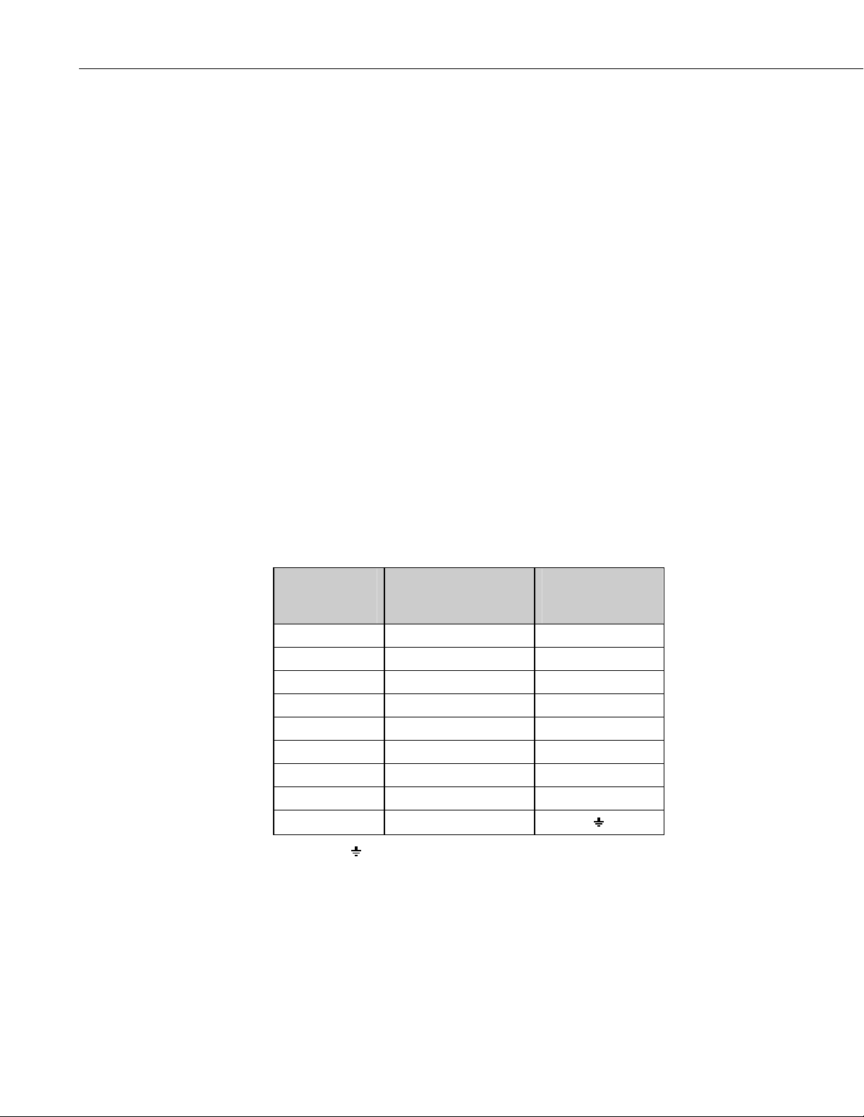
TABLE 4.2-1. Internal Electrical Diagram of the NR01
(for servicing purposes only)
PCB04
Connection
3
4
5
6
13
14
9
10
Table 4-2 shows the NR01 wiring connections for the four radiation outputs,
Pt-100 temperature sensor, and the heater. Table 4.2-1 shows the internal
connections to the terminal blocks, which should only be required for
servicing, e.g. cable replacement.
PCB04
Terminal
Pyranometer
UP
Pyranometer
UP
Pyranometer
DOWN
Pyranometer
DOWN
PCB05
Connection
8
7
12
11
PCB05
Terminal
Pyrgeometer
UP
Pyrgeometer
UP
Pyrgeometer
DOWN
Pyrgeometer
DOWN
Polarity
-
+
-
+
+
-
+
-
WARNING
The sensor has two cables with similar color schemes.
It is important to make sure you identify cable 1 and
cable 2 correctly, especially before connecting any
source of power such as to the heater. Failure to do
so may damage the sensor.
4.3 Connecting the Sensor to Campbell Scientific Dataloggers
This section shows the typical connection schemes.
The four radiation outputs can be measured using Differential (Table 4.3-1) or
Single-Ended inputs on the datalogger (Table 4.3-2). A differential voltage
measurement (VoltDiff or Instruction 2) is recommended because it has better
noise rejection than a single-ended measurement. When differential inputs are
used, jumper the low side of the input to AG or
the common mode range.
to keep the signal within
17
Page 22

NR01 Four-Component Net Radiation Sensor
TABLE 4.3-1. Datalogger Connections for Differential Measurement, when using a 4WPB100
Wire Label Color (cable 1) CR10X CR1000, CR23X, CR7
Pyranometer Up Sig Red Differential Input (H) Differential Input (H)
Pyranometer Up Ref *Blue Differential Input (L) Differential Input (L)
Pyranometer Down Sig White Differential Input (H) Differential Input (H)
Pyranometer Down Ref *Green Differential Input (L) Differential Input (L)
Pyrgeometer Up Sig Brown Differential Input (H) Differential Input (H)
Pyrgeometer Up Ref *Yellow Differential Input (L) Differential Input (L)
Pyrgeometer Down Sig Purple Differential Input (H) Differential Input (H)
Pyrgeometer Down Ref *Grey Differential Input (L) Differential Input (L)
Shield Shield G
*Jumper to AG or with user supplied wire.
TABLE 4.3-2. Datalogger Connections for Single-Ended Measurement, when using a 4WPB100
Wire Label Color (Cable 1) CR10X CR1000, CR23X, CR7
Pyranometer Up Sig Red Single-Ended Input Single-Ended Input
Pyranometer Up Ref Blue AG
Pyranometer Down Sig White Single-Ended Input Single-Ended Input
Pyranometer Down Ref Green AG
Pyrgeometer Up Sig Brown Single-Ended Input Single-Ended Input
Pyrgeometer Up Ref Yellow AG
Pyrgeometer Down Sig Purple Single-Ended Input Single-Ended Input
Pyrgeometer Down Ref Grey AG
Shield Shield G
All dataloggers apart from the CR3000 and CR5000 require the 4WPB100
module to interface the PT-100 to the datalogger. Table 4.3-3 shows the
wiring connections for the 4WPB100 (note this is using cable 2).
TABLE 4.3-3. Pt-100 Temperature Sensor Connections to 4WPB100 and Datalogger
Wire Label Color (Cable 2) 4WPB100 Datalogger
Black Wire Voltage Excitation (VX)
H Differential Input (H)
Current Excite Red L Differential Input (L)
Current Return Blue G (AG CR10X)
PT100 Signal White Differential Input (H)
PT100 Signal Ref Green Differential Input (L)
18
Page 23

NR01 Four-Component Net Radiation Sensor
The PT-100 sensor can connect directly to the CR3000 and CR5000
dataloggers because they have current excitation outputs. Refer to Table 4.3-4
and Program Example 5.2.2 for information on using the current excitation
technique with a CR3000 or CR5000 datalogger.
TABLE 4.3-4. CR3000 and CR5000 Connections
for Differential Measurement and using the Current Excitation to
Measure the PT100 Sensor
Wire Label Color CR3000/CR5000
Pyranometer Up Sig
Pyranometer Up Ref
Pyranometer Down Sig
Pyranometer Down Ref
Pyrgeometer Up Sig
Pyrgeometer Up Ref
Pyrgeometer Down Sig
Pyrgeometer Down Ref
PT100 Signal
PT100 Signal Ref
Red
*Blue
White
*Green
Brown
*Yellow
Purple
*Grey
**White
**Green
Differential Input (H)
Differential Input (L)
Differential Input (H)
Differential Input (L)
Differential Input (H)
Differential Input (L)
Differential Input (H)
Differential Input (L)
Differential Input (H)
Differential Input (L)
Current Excite **Red Current Excitation IX
Current Return - **Blue Current Excitation IXR
Shield (both cables) Clear
*Jumper to AG or with user-supplied wire.
**Note these are in Cable 2.
4.3.1 Connecting and Using the Heater
Only use the sensor heater when there is risk of dew forming on the sensors,
especially for low power installations. Furthermore, the heater should be
turned on and off infrequently as it may take some time for the sensor to come
to thermal equilibrium. No damage will result if the heater is powered
permanently, but as with all thermopile sensors, it is best if the sensor operates
at ambient temperatures and is not subject to rapidly changes of temperature.
The sensor power can be controlled using one of the 12V power switches built
into Campbell dataloggers or using an external solid-state switch such as a
PSW12/SW12. The heater current drain is approximately 140 mA from a 12 V
battery. Connect the ground return from the heater, either directly to the
battery, or to a G terminal close the power input to the logger (i.e., not to an
analog ground near the measurement inputs).
The heater power can be controlled by adding instructions to the datalogger
program, that turns on the heater only when the light level falls below 20 W m
2
or, if a measurement of air humidity is available, when the dew point of the
air falls to within 1ºC of the sensor body temperature. Appendix A provides an
example CR3000/CR5000 program that controls the NR01 heater.
-
19
Page 24

NR01 Four-Component Net Radiation Sensor
4.4 Installation of the Radiation Shields
Radiation shields can be installed and removed using a hex-head wrench (bolt
size 2.0 mm). See the drawing below. Radiation shields are beneficial for
instrument measurement accuracy and instrument and cable lifetime. They also
serve as rain- and snow shield. However, the instrument should function within
specifications without the radiation shield.
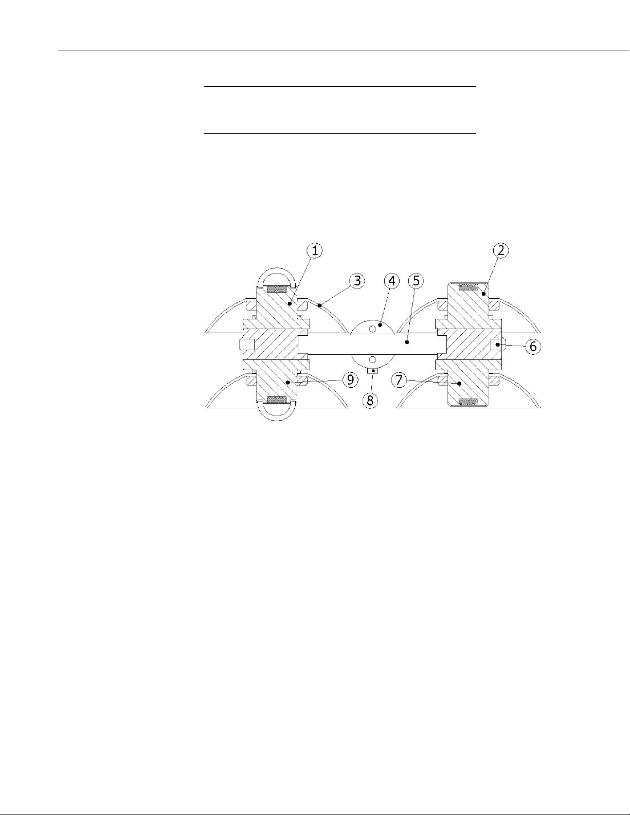
FIGURE 4.4-1. Installation and Removal of Radiation Shields:
(1) Hex-Head Wrench, (2) Radiation Screen
(3) Hexagon Drive Set Screw
4.5 Instrument-Inversion-Test
Campbell Scientific recommends performing the instrument-inversion test after
installation. This test consists of inverting the instrument position (180 degrees
turn) and looking at the output signals. The instrument output should have the
same magnitude but a reversed sign (so + to – and – to +). For best results,
perform this test on a clear day—preferably around noon (with the sun high in
the sky).
Roughly speaking, deviations within ±10% can be tolerated. For optimal
testing of pyrgeometers, the test should be repeated on a clear night.
5. Datalogger Programming
The NR01 outputs four voltages that typically range from 0 to 50 mV for the
SR01 sensors, and ±5 mV for the IR01 sensors. A differential voltage
measurement (VoltDiff in CRBasic or Instruction 2 in Edlog) is recommended
because it has better noise rejection than a single-ended measurement. If
differential channels are not available, a single-ended measurement (VoltSE or
Instruction 1) can be used. The acceptability of a single-ended measurement
can be determined by simply comparing the results of single-ended and
differential measurements made under the same conditions.
20
Page 25

NR01 Four-Component Net Radiation Sensor
For the CR3000 and CR5000 dataloggers, one differential channel and a
current excitation channel are used to measure the PT-100.
For the other dataloggers, two differential channels and the 4WPB100 module
are required to measure the Pt-100 temperature sensor.
NOTE
If free channels are limited it is possible to measure the PT100
sensor using a 3WHB10K terminal input module, with only a
slight loss of accuracy. This only requires one differential
channel. Please refer to the documentation for that module for
further details.
5.1 Calibration Factors
Each NR01 is provided with a ‘Certificate of Calibration’ by the manufacturer.
This certificate shows the sensor serial number and ‘sensitivity’ of each of the
four component sensors. Unlike some other models of sensor, the individual
components are not modified in an attempt to have a common calibration.
Therefore, individual calibration factors must be applied in the datalogger
program to convert the voltages to energy fluxes in W m
The calibration factor is in units of uV/(W m
units of (W m
To convert the units, divide the calibration factor into 1000. For example, if
the calibration factor is 7.30 uV/(W m
-2
)/mV.
(W m
FIGURE 5-1. 4WPB100 Module
-2
-2
-2
)/mV for the multiplier parameter in the datalogger program.
-2
), which needs to be converted to
), the multiplier is 1000/7.3 = 136.99
21
Page 26
NR01 Four-Component Net Radiation Sensor
5.2 Example Programs
5.2.1 Example 1, CR1000 Using Differential Channels
Program Example 1 requires six differential channels and the 4WPB100
module to measure the four radiation outputs and the Pt-100 temperature
sensor, connected on differential channels 1..6. The program measures the
sensors every two seconds, then calculates and stores the following data to
final storage every 60 minutes:
Year
Julian Day
Hour/Minute
Avg SR01 Up (short wave radiation)
Avg SR01 Down (short wave radiation)
Avg IR01 Up (long wave radiation)
Avg IR01 Down (long wave radiation)
Avg NR01 temperature (degrees C)
Avg NR01 temperature (degrees K)
Avg Net shortwave radiation
Avg Net long wave radiation
Avg Albedo
Avg Total Net radiation
Avg temperature corrected IR01 Up
Avg temperature corrected IR01 Down
Wiring for Program Example 1
Color
Red SR01 Up Signal 1H
*Blue SR01 Up Reference 1L
White SR01 Down Signal 2H
*Green SR01 Down Reference 2L
Brown IR01 Up Signal 3H
*Yellow IR01 Up Reference 3L
Purple IR01 Down Signal 4H
*Grey IR01 Down Reference 4L
Shield Shield
*Jumper to with user supplied wire.
Function
Example CR1000
Program
Channels Used
22
Page 27

NR01 Four-Component Net Radiation Sensor
Pt-100 Temperature Sensor Connections to 4WPB100 and Datalogger
Color Function 4WPB100 CR1000
Black Wire EX1
H 5H
Red Pt-100 Excitation + L 5L
Blue Pt-100 Excitation - G
White Pt-100 Signal + 6H
Green Pt-100 Signal - 6L
'CR1000
'Declare Variables and Units
Public Batt_Volt
Public SR01Up
Public SR01Dn
Public IR01Up
Public IR01Dn
Public NR01TC
Public NR01TK
Public NetRs
Public NetRl
Public Albedo
Public UpTot
Public DnTot
Public NetTot
Public IR01UpCo
Public IR01DnCo
Units Batt_Volt=Volts
Units SR01Up=W/m2
Units SR01Dn=W/m2
Units IR01Up=W/m2
Units IR01Dn=W/m2
Units NR01TC=Deg C
Units NR01TK=K
Units NetRs=W/m2
Units NetRl=W/m2
Units Albedo=W/m2
Units UpTot=W/m2
Units DnTot=W/m2
Units NetTot=W/m2
Units IR01UpCo=W/m2
Units IR01DnCo=W/m2
‘Typical data on the calibration sheet might be
‘ Sensitivity uV/W/m^2
‘Pyranometer UP SR01 15.35
‘Pyranometer DOWN SR01 13.30
‘Pyrgeometer UP IR01 8.5
‘Pyrgeometer DOWN IR01 8.2
23
Page 28

NR01 Four-Component Net Radiation Sensor
‘So load the four calibration coefficients specific to this sensor (1000/Sensitivity)
Const SR01Upcal = 65.146
Const SR01Downcal = 75.18
Const IR01Upcal = 117.65
Const IR01Downcal = 121.95
'Define Data Tables
DataTable(Table1,True,-1)
DataInterval(0,60,Min,10)
Average(1,SR01Up,FP2,False)
Average(1,SR01Dn,FP2,False)
Average(1,IR01Up,FP2,False)
Average(1,IR01Dn,FP2,False)
Average(1,NR01TC,FP2,False)
Average(1,NR01TK,FP2,False)
Average(1,NetRs,FP2,False)
Average(1,NetRl,FP2,False)
Average(1,Albedo,FP2,False)
Average(1,UpTot,FP2,False)
Average(1,DnTot,FP2,False)
Average(1,NetTot,FP2,False)
Average(1,IR01UpCo,FP2,False)
Average(1,IR01DnCo,FP2,False)
EndTable
'Main Program
BeginProg
Scan(2,Sec,1,0)
'Default Datalogger Battery Voltage measurement Batt_Volt:
Battery(Batt_Volt)
'NR01 Net Radiometer measurements SR01Up, SR01Dn, IR01Up, IR01Dn, NR01TC, NR01TK,
'NetRs, NetRl, Albedo, UpTot, DnTot, NetTot, IR01UpCo, and IR01DnCo
‘For the CR1000, use autorange for the SR01 measurements due to the wide dynamic range
* VoltDiff(SR01Up,1,autorange,1,True,0,_50Hz,SR01UpCal,0)
* VoltDiff(SR01Dn,1,autorange,2,True,0,_50Hz,SR01DownCal,0)
* VoltDiff(IR01Up,1,mV7_5,3,True,0,_50Hz,IR01Upcal,0)
* VoltDiff(IR01Dn,1,mV7_5,4,True,0,_50Hz,IR01DownCal,0)
** BrHalf4W (NR01TC,1,mV25,mV25,5,Vx1,1,2100,True ,True ,0,250,1.0,0)
PRT(NR01TC,1,NR01TC,1,0)
NR01TK=NR01TC+273.15
NetRs=SR01Up-SR01Dn
NetRl=IR01Up-IR01Dn
Albedo=SR01Dn/SR01Up
UpTot=SR01Up+IR01Up
DnTot=SR01Dn+IR01Dn
NetTot=UpTot-DnTot
IR01UpCo=IR01Up+5.67*10^-8*NR01TK^4
IR01DnCo=IR01Dn+5.67*10^-8*NR01TK^4
'Call Data Tables and Store Data
CallTable(Table1)
NextScan
EndProg
24
Note: Proper entries will vary with program and input channel usage. For other loggers use:
* mV50 range for the CR3000/5000
** mV50 range (both) with 4200 mV excitation for CR3000/5000
Page 29

NR01 Four-Component Net Radiation Sensor
5.2.2 Example 2, CR3000/CR5000 Using Differential Channels (no 4WPB100)
Program Example 2 requires five differential channels and one current
excitation channel to measure the four radiation outputs and the Pt-100
temperature sensor. Connection details are given in the header of the program
below. The program measures the sensors every second and calculates and
stores the following data to final storage every 60 minutes:
Year
Julian Day
Hour/Minute
Avg SR01 Up (shortwave radiation)
Avg SR01 Down (shortwave radiation)
Avg IR01 Up (longwave radiation)
Avg IR01 Down (longwave radiation)
Avg NR01 temperature (degrees C)
Avg NR01 temperature (degrees K)
Avg Net shortwave radiation
Avg Net longwave radiation
Avg Albedo
Avg Total Net radiation
Avg temperature corrected IR01 Up
Avg temperature corrected IR01 Down
'CR3000 or CR5000 Series Datalogger
'ANALOG INPUT
'1H SR01 UP - downwelling shortwave radiation signal (red)
'1L SR01 UP - downwelling shortwave radiation signal reference (blue)
'gnd NR01 shield (clear)
'2H SR01 DOWN - upwelling shortwave radiation signal (white)
'2L SR01 DOWN - upwelling shortwave radiation signal reference (green)
'3H IR01 UP - downwelling longwave radiation signal (brown)
'3L IR01 UP - downwelling longwave radiation signal reference (yellow)
'4H IR01 DOWN - upwelling longwave radiation signal (purple)
'4L IR01 DOWN - upwelling longwave radiation signal reference (grey)
'6H NR01 Pt100 (white)
'6L NR01 Pt100 (green)
'Current Excitation
'IX1 NR01 Pt100 (red)
'IXR NR01 Pt100 (blue)
'Declare Variables and Units
Public Batt_Volt
Public SR01Up
Public SR01Dn
Public IR01Up
Public IR01Dn
Public NR01TC
Public NR01TK
25
Page 30

NR01 Four-Component Net Radiation Sensor
Public NetRs
Public NetRl
Public Albedo
Public UpTot
Public DnTot
Public NetTot
Public IR01UpCo
Public IR01DnCo
Units Batt_Volt = Volts
Units SR01Up = W/m2
Units SR01Dn = W/m2
Units IR01Up = W/m2
Units IR01Dn = W/m2
Units NR01TC = Deg C
Units NR01TK = K
Units NetRs = W/m2
Units NetRl = W/m2
Units Albedo = W/m2
Units UpTot = W/m2
Units DnTot = W/m2
Units NetTot = W/m2
Units IR01UpCo = W/m2
Units IR01DnCo = W/m2
'Load the four calibration coefficients specific to this sensor (see example 1)
Const SR01Upcal = 65.146
Const SR01Downcal = 75.18
Const IR01Upcal = 117.65
Const IR01Downcal = 121.95
'Define Data Tables
DataTable(Table1,True,-1)
DataInterval(0,60,Min,10)
Average(1,SR01Up,FP2,False)
Average(1,SR01Dn,FP2,False)
Average(1,IR01Up,FP2,False)
Average(1,IR01Dn,FP2,False)
Average(1,NR01TC,FP2,False)
Average(1,NR01TK,FP2,False)
Average(1,NetRs,FP2,False)
Average(1,NetRl,FP2,False)
Average(1,Albedo,FP2,False)
Average(1,UpTot,FP2,False)
Average(1,DnTot,FP2,False)
Average(1,NetTot,FP2,False)
Average(1,IR01UpCo,FP2,False)
Average(1,IR01DnCo,FP2,False)
EndTable
'Main Program
BeginProg
Scan(1,Sec,1,0)
'Default Datalogger Battery Voltage measurement Batt_Volt:
Battery(Batt_Volt)
26
Page 31

NR01 Four-Component Net Radiation Sensor
'NR01 Net Radiometer measurements SR01Up, SR01Dn, IR01Up, IR01Dn, NR01TC, NR01TK,
'NetRs, NetRl, Albedo, UpTot, DnTot, NetTot, IR01UpCo, and IR01DnCo
'Uses fixed ranges as they fall more in line with the range of sensor outputs, so no need to
'autorange
VoltDiff(SR01Up,1,mV50,1,True,200,250,SR01Upcal,0)
VoltDiff(SR01Dn,1,mV50,2,True,200,250,SR01DownCal,0)
VoltDiff(IR01Up,1,mV20,3,True,200,250,IR01Upcal,0)
VoltDiff(IR01Dn,1,mV20,4,True,200,250,IR01DownCal,0)
'Note maximum sensor temperature with this excitation setting is just over +50 C.
Resistance (NR01TK,1,mV200,6,Ix1,1,1675,True ,True,200,250,1.0,0)
'Formulate the ratio Rs/R0
NR01TK=NR01TK/100
PRT(NR01TK,1,NR01TK,1,273.15)
'Compute Net short-wave radiation, Net long-wave radiation, Albedo and Net Radiation
NR01TC=NR01TK-273.15
NetRs=SR01Up-SR01Dn
NetRl=IR01Up-IR01Dn
Albedo=SR01Dn/SR01Up
UpTot=SR01Up+IR01Up
DnTot=SR01Dn+IR01Dn
NetTot=UpTot-DnTot
IR01UpCo=IR01Up+5.67*10^-8*NR01TK^4
IR01DnCo=IR01Dn+5.67*10^-8*NR01TK^4
'Call Data Tables and Store Data
CallTable(Table1)
NextScan
EndProg
NOTE
Proper entries for the input channels will vary with program and
input channel usage.
5.2.3 Example 3, CR23X Program Using Differential Channels
Program Example 3 requires six differential channels and the 4WPB100
module to measure the four radiation outputs and the Pt-100 temperature
sensor. Wiring is shown in Tables 4.3-1 and 4.3-3 above, using differential
channels 1..5. The program measures the sensors every 2 seconds, then
calculates and stores the following data to final storage every 60 minutes:
Array ID
Year
Julian Day
Hour/Minute
Avg SR01 Up (shortwave radiation)
Avg SR01 Down (shortwave radiation)
Avg IR01 Up (longwave radiation)
Avg IR01 Down (longwave radiation)
Avg NR01 temperature (degrees C)
Avg NR01 temperature (degrees K)
Avg Net shortwave radiation
Avg Net longwave radiation
27
Page 32

NR01 Four-Component Net Radiation Sensor
Avg Albedo
Avg Total Net radiation
Avg temperature corrected IR01 Up
Avg temperature corrected IR01 Down
;{CR23X}
;Program Example 3 for CR23X datalogger
;
;*Table 1 Program
01: 2 Execution Interval (seconds)
;Measure all four sensor elements with one instruction, use auto-ranging for best resolution
1: Volt (Diff) (P2)
1: 4 Reps
2: 30 Auto, 50 Hz Reject, Slow Range (OS>1.06)
3: 1* DIFF Channel
4: 1 Loc [ SR01_up ]
5: 1.0 Multiplier
6: 0.0 Offset
;Apply the individual calibration factors to each component
;with one scaling instruction
;Typical data on the data sheet might be
;Sensor Sensitivity uV/W/m^2
;Pyranometer UP SR01 15.35
;Pyranometer DOWN SR01 13.30
;Pyrgeometer UP IR01 8.5
;Pyrgeometer DOWN IR01 8.2
; Multipliers calculated at 1000/sensitivity
2: Scaling Array (A*Loc+B) (P53)
1: 1 Start Loc [ SR01_up ]
2: 65.146 A1 ;SR01 up
3: 0 B1
4: 75.18 A2 ;SR01 down
5: 0.0 B2
6: 117.65 A3 ;IR01 up
7: 0.0 B3
8: 121.95 A4 ;IR01 down
9: 0.0 B4
;Measure NR01 temperature
3: Full Bridge w/mv Excit (P9)
1: 1 Reps
2: 32** 50 mV, 50 Hz Reject, Slow, Ex Range
3: 32** 50 mV, 50 Hz Reject, Slow, Br Range
4: 5* DIFF Channel
5: 1 Excite all reps w/Exchan 1
6: 4200*** mV Excitation
7: 5* Loc [ Temp_C ]
8: 1 Mult
9: 0 Offset
28
Page 33

NR01 Four-Component Net Radiation Sensor
4: Temperature RTD (P16)
1: 1 Reps
2: 5 R/R0 Loc [ Temp_C ]
3: 5 Loc [ Temp_C ]
4: 1.0 Mult
5: 0 Offset
5: Z=X+F (P34)
1: 5 X Loc [ Temp_C ]
2: 273.18 F
3: 6 Z Loc [ Temp_K ]
;Net SR01 shortwave radiation = SR01 Up - SR01 Down
6: Z=X-Y (P35)
1: 1 X Loc [ SR01_up ]
2: 2 Y Loc [ SR01_dn ]
3: 7 Z Loc [ Net_Rs ]
;Net IR01 longwave radiation = IR01 Up - IR01 Down
7: Z=X-Y (P35)
1: 3 X Loc [ IR01_up ]
2: 4 Y Loc [ IR01_dn ]
3: 8 Z Loc [ Net_Rl ]
;Albedo = SR01 Down / SR01 Up
8: Z=X/Y (P38)
1: 2 X Loc [ SR01_dn ]
2: 1 Y Loc [ SR01_up ]
3: 9 Z Loc [ Albedo ]
;Net total radiation = (SR01 Up + IR01 Up) - (SR01 Down + IR01 Down)
9: Z=X+Y (P33)
1: 1 X Loc [ SR01_up ]
2: 3 Y Loc [ IR01_up ]
3: 23 Z Loc [ Up_total ]
10: Z=X+Y (P33)
1: 2 X Loc [ SR01_dn ]
2: 4 Y Loc [ IR01_dn ]
3: 24 Z Loc [ Dn_total ]
11: Z=X-Y (P35)
1: 23 X Loc [ Up_total ]
2: 24 Y Loc [ Dn_total ]
3: 10 Z Loc [ Net_total ]
;Correct IR01 Up and IR01 Down for temperature
29
Page 34

NR01 Four-Component Net Radiation Sensor
; IR01_upCor = IR01_up+5.67 10-8 Temp_K4
; IR01_dnCor = IR01_dn+5.67 10-8 Temp_K4
12: Z=F (P30)
1: 5.67 F
2: -8 Exponent of 10
3: 25 Z Loc [ scratch_1 ]
13: Z=F (P30)
1: 4 F
2: 0 Exponent of 10
3: 26 Z Loc [ scratch_2 ]
14: Z=X^Y (P47)
1: 6 X Loc [ Temp_K ]
2: 26 Y Loc [ scratch_2 ]
3: 27 Z Loc [ scratch_3 ]
15: Z=X*Y (P36)
1: 25 X Loc [ scratch_1 ]
2: 27 Y Loc [ scratch_3 ]
3: 28 Z Loc [ scratch_4 ]
16: Z=X+Y (P33)
1: 3 X Loc [ IR01_up ]
2: 28 Y Loc [ scratch_4 ]
3: 11 Z Loc [ IR01_upCor ]
17: Z=X+Y (P33)
1: 4 X Loc [ IR01_dn ]
2: 28 Y Loc [ scratch_4 ]
3: 12 Z Loc [ IR01_dnCor ]
;
;Output data to final storage every 60 minutes
18: If time is (P92)
1: 0 Minutes (Seconds --) into a
2: 60 Interval (same units as above)
3: 10 Set Output Flag High (Flag 0)
19: Real Time (P77)
1: 0220 Day,Hour/Minute (midnight = 2400)
20: Average (P71)
1: 12 Reps
2: 1 Loc [ SR01_dn ]
30
Note: Proper entries will vary with program and *input channel usage. For other loggers use:
** 25 mV range for CR10X, 50 mV for 21X and CR7
*** 4200 mV for 21X and CR7, 2100 mV for CR10X
Page 35

NR01 Four-Component Net Radiation Sensor
5.2.4 Example 4, CR23X Program Using Single-Ended Channels
Program Example 4 requires four single-ended channels to measure the four
radiation outputs, and four single-ended channels and one differential channel
for the 4WPB100 module to measure the Pt-100 temperature sensor. Wiring is
as in Table 4.3-2, using SE channels 1..4 and 4.5 above using differential
channel 3 and 4 for the PT100 sensor. The program measures the sensors every
2 seconds, then stores the following data to final storage every 60 minutes:
Array ID
Year
Day
Hour/Minute
Avg SR01 down (shortwave radiation)
Avg SR01 up (shortwave radiation)
Avg IR01 down (longwave radiation)
Avg IR01 up (longwave radiation)
Avg NR01 temperature (degrees C)
Avg NR01 temperature (degrees K)
;{CR23X}
;Example for SE measurements of the NR01 using a CR23X
;
*Table 1 Program
01: 2 Execution Interval (seconds)
;Measure all four sensor elements with one instruction, use auto-ranging for best resolution
1: Volt (SE) (P1)
1: 4 Reps
2: 30 Auto, 50 Hz Reject, Slow Range (OS>1.06)
3: 1* SE Channel
4: 1 Loc [ SR01_up ]
5: 1.0 Multiplier
6: 0.0 Offset
;Apply the individual calibration factors to each component
;with one instruction
;Typical data on the data sheet might be
;Sensor Sensitivity uV/W/m^2
;Pyranometer UP SR01 15.35
;Pyranometer DOWN SR01 13.30
;Pyrgeometer UP IR01 8.5
;Pyrgeometer DOWN IR01 8.2
; Multipliers calculated at 1000/sensitivity
31
Page 36

NR01 Four-Component Net Radiation Sensor
2: Scaling Array (A*Loc+B) (P53)
1: 1 Start Loc [ SR01_up ]
2: 65.146 A1 ;SR01 up
3: 0 B1
4: 75.18 A2 ;SR01 down
5: 0.0 B2
6: 117.65 A3 ;IR01 up
7: 0.0 B3
8: 121.95 A4 ;IR01 down
9: 0.0 B4
;Measure the IR01 temperature
3: Full Bridge w/mv Excit (P9)
1: 1 Reps
2: 32 50 mV, 50 Hz Reject, Slow, Ex Range**
3: 32 50 mV, 50 Hz Reject, Slow, Br Range**
4: 3* DIFF Channel
5: 1 Excite all reps w/Exchan 1
6: 4200 mV Excitation***
7: 5 Loc [ IR01_TC ]
8: 1 Multiplier
9: 0.0 Offset
4: Temperature RTD (P16)
1: 1 Reps
2: 5 R/R0 Loc [ IR01_TC ]
3: 5 Loc [ IR01_TC ]
4: 1.0 Multiplier
5: 0.0 Offset
;Also create a temperature in K for use in optional online
;calculation of fluxes
5: Z=X+F (P34)
1: 5 X Loc [ IR01_TC ]
2: 273.15 F
3: 6 Z Loc [ IR01_TK ]
;In this example just output the scaled flux measurements
6: If time is (P92)
1: 0 Minutes (Seconds --) into a
2: 60 Interval (same units as above)
3: 10 Set Output Flag High (Flag 0)
7: Real Time (P77)
1: 0220 Day,Hour/Minute (midnight = 2400)
8: Average (P71)
1: 6 Reps
2: 1 Loc [ SR01_up ]
32
Note: Proper entries will vary with program and *input channel usage. For other loggers use:
** 25 mV range for CR10X, 50 mV for 21X and CR7
*** 4200 mV for 21X and CR7, 2100 mV for CR10X
Page 37

NR01 Four-Component Net Radiation Sensor
6. Maintenance and Troubleshooting
6.1 Maintenance
Once installed the NR01 is essentially maintenance free apart from cleaning
dirt off the domes every few weeks. Usually errors in functionality will appear
as unreasonably large or small measured values.
As a general rule, this means that a critical review of the measured data is the
best form of maintenance.
At regular intervals the quality of the cables can be checked.
On a 2 yearly interval the calibration can be checked in an indoor facility.
TABLE 6.1-1. The NR01 Recommendations for Maintenance
Critical review of data
Cleaning of dome using water or alcohol
Inspection of dome interior; no condensation
Inspection of cables for open connections
For the NR01: sensor inversion test as in 4.5.
Recalibration: suggested every 2 years, typically by intercomparison with
a higher standard in the field.
33
Page 38

NR01 Four-Component Net Radiation Sensor
6.2 Troubleshooting
This table contains information used to diagnosis problems whenever the
sensor does not function properly.
TABLE 6.2-1. Troubleshooting for the NR01
The sensor does
not give any
signal
The sensor signal
is unrealistically
high or low.
The sensor signal
shows
unexpected
variations
Typically an error is due to either a short circuit or an
open connection. Both can be detected by impedance /
resistance measurements at the cable end.
In case of open circuits: open the instrument and check
the internal connections (see wiring diagram of Table 4.2-
1.)
Check if the right calibration factors are entered into the
algorithm. Please note that each sensor has its own
individual calibration factor.
Check if the voltage reading is divided by the calibration
factor by review of the algorithm.
Check the condition of the leads at the logger.
Check the cabling condition looking for cable breaks.
Check the data acquisition by applying an mV source to it
in the 1 mV range.
Perform a sensor-inversion test as written down in 4.5.
Open the instrument and check the internal connections
(see wiring diagram of Table 4.2-1).
Check the presence of strong sources of electromagnetic
radiation (radar, radio etc.)
Check the condition of the shielding.
Check the condition of the sensor cable.
Open the instrument and check the internal connections
(see wiring diagram of Table 4.2-1).
34
Page 39

Appendix A. CR3000 Program that Controls the Heater
This program applies power to the NR01 heater using the SW12V relay
controller and the pulse width modulation instruction (PWM ()).
Rather than using 0 degrees C as a set point for the heater, the program below
uses the dew point value. The datalogger calculates dew point using the
relative humidity (RH) measurements provided by the HMP45C
Temperature/Relative Humidity probe. Enter 0 degrees C as the set point for
the heater when a temperature/RH probe is not used.
The algorithm turns the heater on/off at 4 Hz. The duty cycle of the pulse is
changed depending on how close the radiometer body temperature is to the
dew point temperature. At or below the dew point, the duty cycle is 100%. It
drops off linearly to 20% until the body temperature is 5 degrees C above the
dew point. For body temperatures greater than 5 degrees C above the dew
point, the duty cycle continue to drop linearly, but with a different slope, until
0% at 33 degrees C above the dew point. If necessary, the user can change the
two duty-cycle slope transitions.
'CR3000 Series Datalogger
'*** Wiring ***
'ANALOG INPUT
'5H HMP45C temperature signal (yellow)
'5L HMP45C signal reference (white)
'gnd HMP45C shield (clear)
'6H HMP45C relative humidity signal (blue)
'6L short jumper wire to 5L
'10H NR01 Pt100 signal (white)
'10L NR01 Pt100 signal reference (green)
'gnd NR 01 Pt100 shield (silver)
'11H NR01 downwelling shortwave radiation signal (red)
'11L NR01 downwelling shortwave radiation signal reference (blue)
'gnd NR01 shield (silver)
'12H NR01 upwelling shortwave radiation signal (white)
'12L NR01 upwelling shortwave radiation signal reference (green)
'13H NR01 downwelling longwave radiation signal (brown)
'13L NR01 downwelling longwave radiation signal reference (yellow)
'14H NR01 upwelling longwave radiation signal (purple or pink)
'14L NR01 upwelling longwave radiation signal reference (gray)
A-1
Page 40

Appendix A. CR3000 Program that Controls the Heater
'CURRENT EXCITATION
'IX1 NR01 Pt100 current excitation (red)
'IXR NR01 Pt100 current excitation reference (blue)
'CONTROL PORTS
'C1 SW12V control (green)
'G SW12V control/power reference (black)
'POWER OUT
'12V HMP45C power (red)
' SW12V power (red)
'G HMP45C power reference (black)
'POWER IN
'12V datalogger (red)
'G datalogger (black)
'EXTERNAL POWER SUPPLY
'POS datalogger (red)
'NEG datalogger (black)
'SW12V Power Control Module
'SW12V NR 01 heater excitation (brown)
'G NR 01 heater excitation reference (yellow)
PipeLineMode
'*** Constants ***
Const NR01_SHORT_DW_CAL = 1000/13.41 'Unique NR 01 shortwave downwelling multiplier (1000/15.5).
Const NR01_SHORT_UW_CAL = 1000/13.93 'Unique NR 01 shortwave upwelling multiplier (1000/13.5).
Const NR01_LONG_DW_CAL = 1000/8.8 'Unique NR 01 longwave downwelling multiplier (1000/10.5).
Const NR01_LONG_UW_CAL = 1000/9.4 'Unique NR 01 longwave upwelling multiplier (1000/10.3).
Const MAX_DUTY_CYCLE_1 = 1
Const MAX_DUTY_CYCLE_2 = 0.2
Const DELTA_SET_POINT_1 = 5
Const DELTA_SET_POINT_2 = 28
Const SLOPE_1 = (MAX_DUTY_CYCLE_2-MAX_DUTY_CYCLE_1)/DELTA_SET_POINT_1
Const SLOPE_2 = (-MAX_DUTY_CYCLE_2)/DELTA_SET_POINT_2
'*** Variables ***
Public no_heat_flag As Boolean 'Turn off heater control when TRUE.
Public panel_temp 'Datalogger panel temperature.
Public batt_volt 'Datalogger battery voltage.
Public hmp(2) 'HMP45C temperature and relative humidity.
Alias hmp(1) = t_hmp 'HMP45C temperature.
Alias hmp(2) = rh_hmp 'HMP45C relative humidity.
Public e_hmp 'HMP45C vapor pressure.
Public nr01(9) 'NR 01 net radiometer.
Alias nr01(1) = Rn
Alias nr01(2) = albedo
Alias nr01(3) = Rs_downwell
Alias nr01(4) = Rs_upwell
A-2
Page 41

Appendix A. CR3000 Program that Controls the Heater
Alias nr01(5) = Rl_downwell
Alias nr01(6) = Rl_upwell
Alias nr01(7) = t_nr01
Alias nr01(8) = Rl_down_meas
Alias nr01(9) = Rl_up_meas
Units panel_temp = C
Units batt_volt = V
Units t_hmp = C
Units rh_hmp = percent
Units e_hmp = kPa
Units nr01 = W/m^2
Units albedo = unitless
Units t_nr01 = K
'Net radiometer heater control variables.
Public set_point_temperature
Public duty_cycle
'Working Variables
Dim scratch_out(3)
Alias scratch_out(1) = t_hmp_mean
Alias scratch_out(2) = e_hmp_mean
Alias scratch_out(3) = e_sat_hmp_mean
Dim rh_hmp_mean 'Mean HMP45C relative humidity.
Dim t_dew_hmp_mean 'Mean dew point temperature.
Dim e_sat_hmp 'HMP45C saturation vapor pressure.
Units t_hmp_mean = C
Units e_hmp_mean = kPa
Units e_sat_hmp_mean = kPa
Units rh_hmp_mean = percent
Units t_dew_hmp_mean = C
DataTable (stats,TRUE,-1)
DataInterval (0,5,Min,10)
Sample (1,t_hmp_mean,IEEE4)
Sample (1,e_hmp_mean,IEEE4)
Sample (1,rh_hmp_mean,IEEE4)
Sample (1,t_dew_hmp_mean,IEEE4)
Sample (1,duty_cycle,IEEE4)
Average (9,Rn,IEEE4,FALSE)
EndTable
DataTable (scratch,TRUE,1)
TableHide
DataInterval (0,5,Min,10)
Average (1,t_hmp,IEEE4,FALSE)
Average (1,e_hmp,IEEE4,FALSE)
Average (1,e_sat_hmp,IEEE4,FALSE)
EndTable
A-3
Page 42

Appendix A. CR3000 Program that Controls the Heater
BeginProg
Scan (1,Sec,0,0)
'Control the net radiometer heater.
PWM (duty_cycle,4,250,mSec)
'Datalogger panel temperature.
PanelTemp (panel_temp,250)
'Measure battery voltage.
Battery (batt_volt)
'Measure the HMP45C temperature and relative humidity.
VoltDiff (t_hmp,1,mV1000C,5,TRUE,200,250,0.1,-40)
VoltDiff (rh_hmp,1,mV1000C,6,TRUE,200,250,0.1,0)
'Measure NR 01 Net Radiometer.
Resistance (t_nr01,1,mV200,10,Ix1,1,1675,TRUE,TRUE,200,250,1,0)
VoltDiff (Rs_downwell,1,mV20C,11,TRUE,200,250,NR01_SHORT_DW_CAL,0)
VoltDiff (Rs_upwell,1,mV20C,12,TRUE,200,250,NR01_SHORT_UW_CAL,0)
VoltDiff (Rl_down_meas,1,mV20C,13,TRUE,200,250,NR01_LONG_DW_CAL,0)
VoltDiff (Rl_up_meas,1,mV20C,14,TRUE,200,250,NR01_LONG_UW_CAL,0)
'Find the HMP45C vapor pressure and saturation vapor pressure (kPa).
VaporPressure (e_hmp,t_hmp,rh_hmp)
SatVP (e_sat_hmp,t_hmp)
'Compute net radiation, albedo, downwelling and upwelling longwave radiation.
t_nr01 = t_nr01/100
PRT (t_nr01,1,t_nr01,1,273.15)
Rn = Rs_downwell-Rs_upwell+Rl_down_meas-Rl_up_meas
albedo = Rs_upwell/Rs_downwell
Rl_downwell = Rl_down_meas+(5.67e-8*t_nr01*t_nr01*t_nr01*t_nr01)
Rl_upwell = Rl_up_meas+(5.67e-8*t_nr01*t_nr01*t_nr01*t_nr01)
CallTable (scratch)
If ( scratch.Output(1,1) ) Then
GetRecord (scratch_out(1),scratch,1)
rh_hmp_mean = 100*e_hmp_mean/e_sat_hmp_mean
DewPoint (t_dew_hmp_mean,t_hmp_mean,rh_hmp_mean)
'Control the NR 01 heater using 4 Hz pulse width modulation. Below the dew
' point temperature applies 100% power. Above the dew point, power is reduced
' linearly to 20% until the dew point plus DELTA_SET_POINT_1. After the dew
' point plus DELTA_SET_POINT_1 and until the dew point plus
' DELTA_SET_POINT_2 plus DELTA_SET_POINT_2, the power is reduced linearly to 0%.
If ( (t_nr01 <> NaN) AND (t_dew_hmp_mean <> NaN) AND (no_heat_flag <> TRUE) ) Then
set_point_temperature = t_dew_hmp_mean+273.15
Select Case t_nr01
Case Is < ( set_point_temperature )
duty_cycle = 1
Case Is < ( set_point_temperature+DELTA_SET_POINT_1 )
duty_cycle = MAX_DUTY_CYCLE_1+(t_nr01-(t_dew_hmp_mean+273.15))*SLOPE_1
A-4
Page 43

Appendix A. CR3000 Program that Controls the Heater
Case Is < ( set_point_temperature+DELTA_SET_POINT_1+DELTA_SET_POINT_2 )
duty_cycle = MAX_DUTY_CYCLE_2+(t_nr01 (t_dew_hmp_mean+273.15+DELTA_SET_POINT_1))*SLOPE_2
Case Else
duty_cycle = 0.01
EndSelect
Else
duty_cycle = 0.01
EndIf
EndIf
CallTable (stats)
NextScan
EndProg
A-5
Page 44

Appendix A. CR3000 Program that Controls the Heater
A-6
Page 45

Page 46

Campbell Scientific Companies
Campbell Scientific, Inc. (CSI)
815 West 1800 North
Logan, Utah 84321
UNITED STATES
www.campbellsci.com • info@campbellsci.com
Campbell Scientific Africa Pty. Ltd. (CSAf)
PO Box 2450
Somerset West 7129
SOUTH AFRICA
www.csafrica.co.za • cleroux@csafrica.co.za
Campbell Scientific Australia Pty. Ltd. (CSA)
PO Box 444
Thuringowa Central
QLD 4812 AUSTRALIA
www.campbellsci.com.au • info@campbellsci.com.au
Campbell Scientific do Brazil Ltda. (CSB)
Rua Luisa Crapsi Orsi, 15 Butantã
CEP: 005543-000 São Paulo SP BRAZIL
www.campbellsci.com.br • suporte@campbellsci.com.br
Campbell Scientific Canada Corp. (CSC)
11564 - 149th Street NW
Edmonton, Alberta T5M 1W7
CANADA
www.campbellsci.ca • dataloggers@campbellsci.ca
Campbell Scientific Centro Caribe S.A. (CSCC)
300 N Cementerio, Edificio Breller
Santo Domingo, Heredia 40305
COSTA RICA
www.campbellsci.cc • info@campbellsci.cc
Campbell Scientific Ltd. (CSL)
Campbell Park
80 Hathern Road
Shepshed, Loughborough LE12 9GX
UNITED KINGDOM
www.campbellsci.co.uk • sales@campbellsci.co.uk
Campbell Scientific Ltd. (France)
3 Avenue de la Division Leclerc
92160 ANTONY
FRANCE
www.campbellsci.fr • info@campbellsci.fr
Campbell Scientific Spain, S. L.
Avda. Pompeu Fabra 7-9, local 1
08024 Barcelona
SPAIN
www.campbellsci.es • info@campbellsci.es
Please visit www.campbellsci.com to obtain contact information for your local US or International representative.
 Loading...