

Page 1

Revision: 01/2021
Copyright © 2019 – 2021
Campbell Scientific, Inc.
Page 2

Table of contents
1. Introduction 1
2. Precautions 1
3. Initial inspection 1
4. QuickStart 2
5. Specifications 4
5.1 Air temperature measurement 7
5.2 Relative humidity measurements 7
5.3 Barometric pressure measurements 7
5.4 Wind speed measurements 8
5.5 Wind direction measurements 8
5.6 Precipitation input 8
5.7 Precipitation measurements 8
5.8 Compass 8
6. Installation 9
6.1 Wiring 9
6.1.1 RS-485 wiring 9
6.1.2 SDI-12 wiring 9
6.1.3 RS-232 wiring 10
6.2 Programming 10
6.2.1 RS-485 programming 11
6.2.1.1 Modbus measurements 12
6.2.2 SDI-12 programming 14
6.2.2.1 SDI-12 measurements 15
6.2.3 RS-232 programming 16
6.3 Siting considerations for wind measurements 16
6.4 Mounting 16
Appendix A. Importing Short Cut code into CRBasic Editor 18
Appendix B. SDI-12 sensor support 19
B.1 SDI-12 command basics 19
Table of Contents - i
Page 3

B.1.1 Acknowledge active command (a!) 20
B.1.2 Send identification command (al!) 20
B.1.3 Start verification command (aV!) 21
B.1.4 Address query command (?!) 21
B.1.5 Change address command (aAb!) 21
B.1.6 Start measurement commands (aM!) 22
B.1.7 Start measurement commands with cyclic redundancy check (aMC! and aCC!) 22
B.1.8 Stopping a measurement command 23
B.1.9 Send data command (aD0! … aD9!) 23
B.2 SDI-12 transparent mode 23
B.2.1 Changing an SDI-12 address 24
Table of Contents - ii
Page 4

1. Introduction
The MetSENS-series compact weather sensors monitor different combinations of common
meteorological parameters to international standards—all in a single, integrated instrument. A
variety of output options ensure plug and play operability in a wide variety of applications.
2. Precautions
l READ AND UNDERSTAND the Safety section at the back of this manual.
l Care should be taken when opening the shipping package to not damage or cut the cable
jacket. If damage to the cable is suspected, consult with a Campbell Scientific support and
implementation engineer.
l Opening the unit or breaking the security seal will void the warranty and the calibration.
l The sensor is a precision instrument. Please handle it with care.
l When installing the unit, handle with lint free gloves and degrease the unit to reduce the
build-up of deposits.
3. Initial inspection
Upon receipt of the MetSENS-series sensor, inspect the packaging and contents for damage. File
damage claims with the shipping company.
Each MetSENS-series sensor is shipped pre-configured, with a test report and cable.
Configuration and cable type depends on the communication mode chosen: SDI-12, Modbus RS485, or RS-232. The cable length can be 5m (17ft), 15m (50ft), 46m (150ft), or user specified.
Replacement cables are as follows:
l METSENSCBL1 SDI-12 Replacement Cable
l METSENSCBL2 RS-485 Replacement Cable
l METSENSCBL3 RS-232 Replacement Cable
MetSENS-Series Compact Weather Sensors 1
Page 5
4. QuickStart
A video that describes data logger programming using Short Cut is available at:
www.campbellsci.com/videos/cr1000x-data logger-getting-started-program-part-3 . Short Cut
is an easy way to program your data logger to measure the sensor and assign data logger wiring
terminals. Short Cut is available as a download on www.campbellsci.com. It is included in
installations of LoggerNet, RTDAQ, PC400, and PC200W.
The following procedure also shows using Short Cut to program the sensor.
1. Open Short Cut and click Create New Program.
2. Double-click the data logger model.
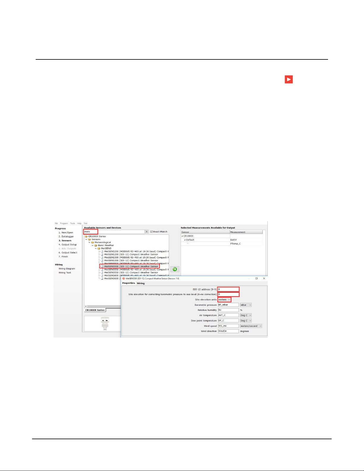
3. In the Available Sensors and Devices box, type MetSENS or locate the sensor in the Sensors
> Meteorological > Basic Weather > MetSENS folder. Double-click the appropriate sensor
model and output. Type the correct SDI-12 Address (default is zero) or Modbus Address
(default is 41). If measuring barometric pressure, type the elevation of the site in the same
units as the Site elevation units. Default units are meters, which can be changed by clicking
on the Site elevation units box and selecting Feet.
MetSENS-Series Compact Weather Sensors 2
Page 6
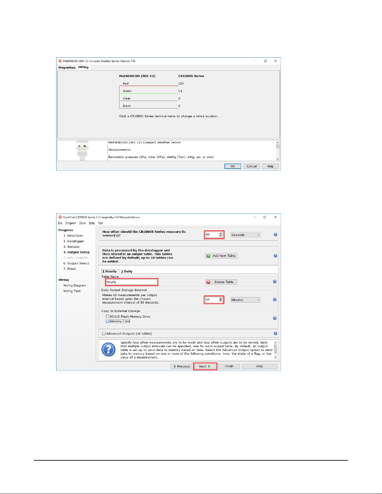
4. Click the Wiring tab to see how the sensor is to be wired to the data logger. Click OK after
wiring the sensor.
5. Repeat steps three and four for other sensors.
6. In Output Setup, type the scan rate, meaningful table names, and Data Output Storage
Interval.
MetSENS-Series Compact Weather Sensors 3
Page 7
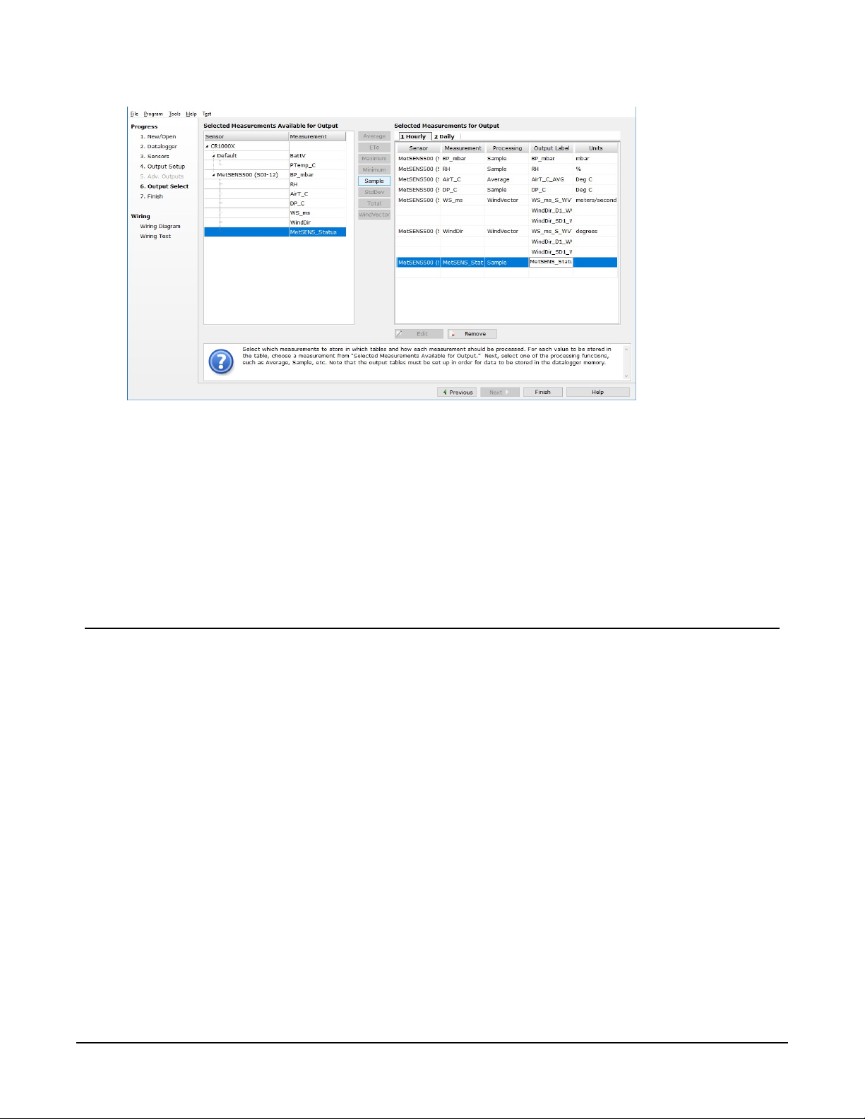
7. Select the measurement and its associated output option.
8. Click Finish and save the program. Send the program to the data logger if the data logger
is connected to the computer.
9. If the sensor is connected to the data logger, check the output of the sensor in the data
display in LoggerNet, RTDAQ, PC400, or PC200W to make sure it is making reasonable
measurements.
5. Specifications
Sampling rate:
Digital communication modes:
Default configuration
RS-485:
SDI-12:
RS-232:
IP rating:
Compliance:
1 Hz
Serial RS-232, RS-485, SDI-12, NMEA, Modbus, ASCII
19200 baud rate, 8 data bits, even parity, one stop bit;
default Modbus address is 41
Default SDI-12 address is 0
9600 baud rate, 8 data bits, even parity, one stop bit
66
CE, RoHS; compliance documents available at:
www.campbellsci.com/metsens200
www.campbellsci.com/metsens300
www.campbellsci.com/metsens500
MetSENS-Series Compact Weather Sensors 4
Page 8
www.campbellsci.com/metsens550
155mm
7.5mm
Ø38.5mm
Ø44.5mm
142mm
www.campbellsci.com/metsens600
Operating temperature range:
Operating voltage:
Typical current drain @ 12 VDC:
–40 to 70 °C
5 to 30 VDC
25 mA continuous high mode,
0.7 mA eco-power mode (1 hour polled)
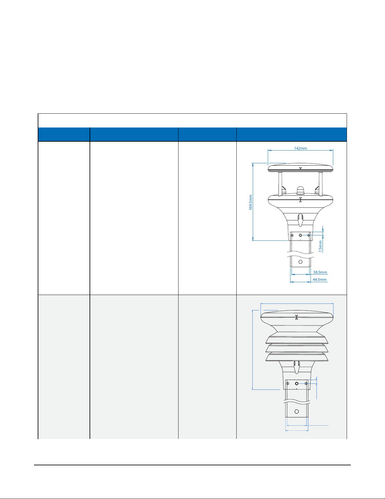
Table 5-1: Measurements, weight, and dimensions
Model Measurements Weight Dimensions
Wind speed
MetSENS200
Wind direction
0.5 kg (1.1 lb)
Compass
MetSENS300
Air temperature
Relative humidity
Barometric pressure
0.5 kg (1.1 lb)
MetSENS-Series Compact Weather Sensors 5
Page 9
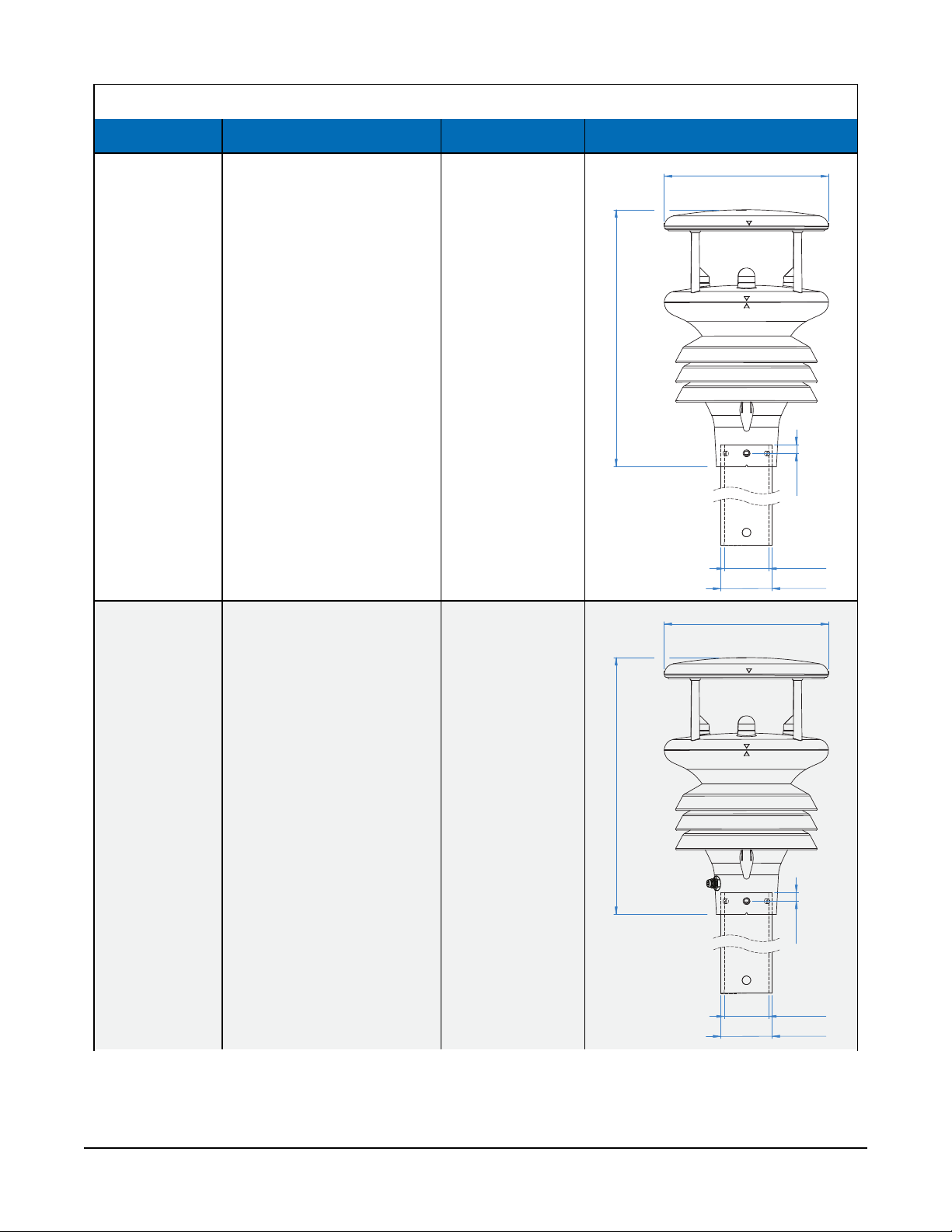
Table 5-1: Measurements, weight, and dimensions
222mm
38.5mm
44.5mm
7.5mm
142mm
222mm
38.5mm
44.5mm
7.5mm
142mm
Model Measurements Weight Dimensions
Air temperature
Relative humidity
Barometric pressure
MetSENS500
0.7 kg (1.5 lb)
Wind speed
Wind direction
Compass
MetSENS550
Air temperature
Relative humidity
Barometric pressure
Wind speed
Wind direction
Compass
Connector for the
TE525METS or other rain
gage
0.7 kg (1.5 lb)
MetSENS-Series Compact Weather Sensors 6
Page 10
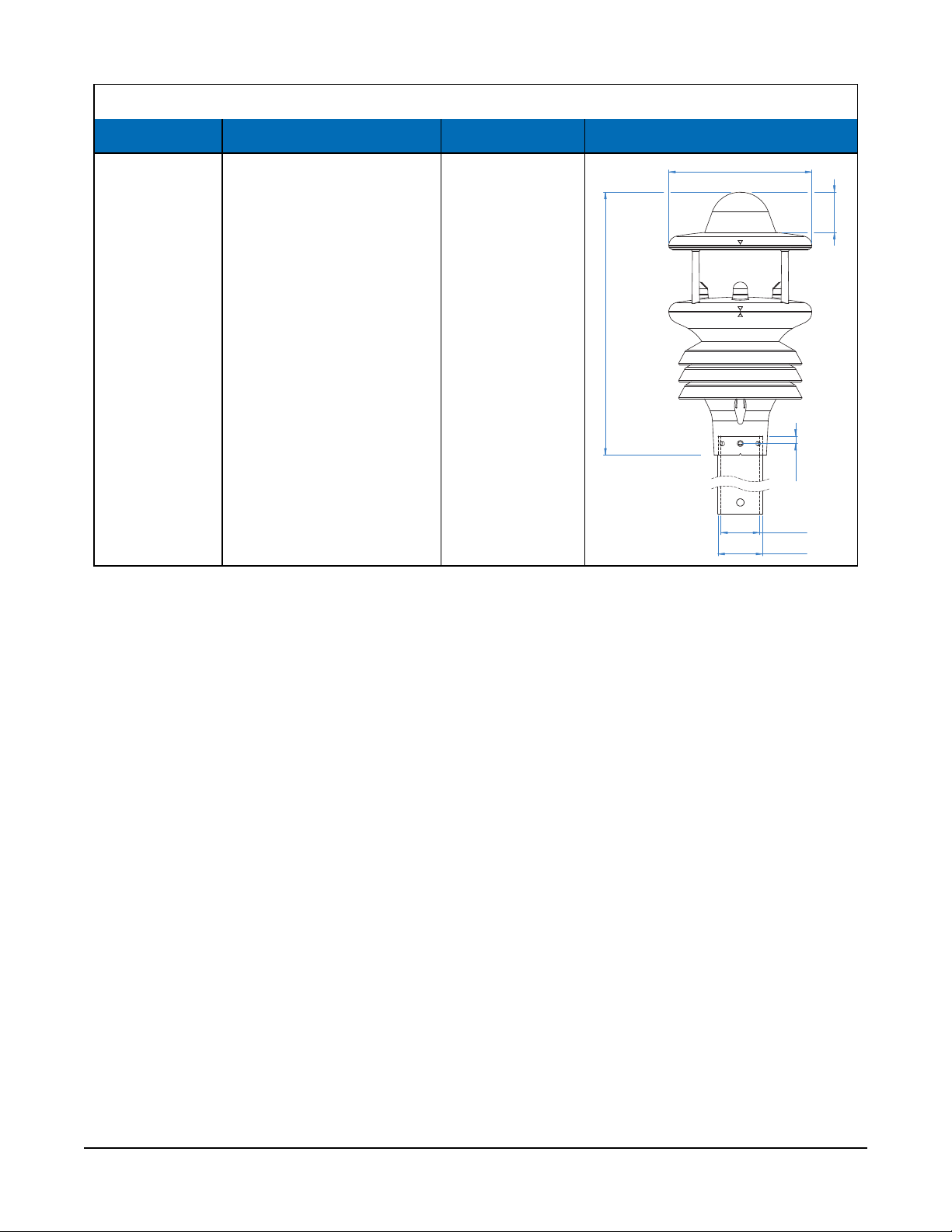
Table 5-1: Measurements, weight, and dimensions
7.5mm
Ø38.5mm
142mm
Ø44.5mm
261mm
40mm
Model Measurements Weight Dimensions
Air temperature
Relative humidity
Barometric pressure
MetSENS600
Wind speed
Wind direction
Compass
Precipitation (optical)
0.8 kg (1.8 lb)
5.1 Air temperature measurement
Measurement range:
Resolution:
Accuracy:
–40 to 70 °C
0.1 °C
±0.3 °C @ +20 °C
5.2 Relative humidity measurements
Measurement range:
Resolution:
Accuracy:
0 to 100%
0.1 %
± 2% @ 20 °C (10 to 90% RH)
5.3 Barometric pressure measurements
Measurement range:
Resolution:
Accuracy:
300 to 1100 hPa
0.1 hPa
±0.5 hPa @ 25 °C
MetSENS-Series Compact Weather Sensors 7
Page 11

5.4 Wind speed measurements
Measurement range:
Resolution:
Starting threshold:
Accuracy:
0.01 to 60 m/s
0.01 m/s
0.01 m/s
±3% (up to 40 m/s), ±5% (up to 60 m/s)
5.5 Wind direction measurements
Measurement range:
Resolution:
Accuracy:
0° to 359°
1°
±3° (up to 60 m/s)
5.6 Precipitation input
Measurement input type:
Range:
Triggering
0 to 1000 mm/hr
Resolution:
Input to MetSENS550:
from 0.01 mm
Contact closure via an M8 male, 4-pin connector.
User-supplied 20 m cable or mating female connector required.
5.7 Precipitation measurements
Measurement input type:
Range:
Resolution:
Repeatability:
Optical
0 to >300 mm/hr
0.08 mm
3%
5.8 Compass
Measurement range:
Resolution:
Units of measure:
0 to 359°
1°
Degrees
Accuracy:
±3°
MetSENS-Series Compact Weather Sensors 8
Page 12

6. Installation
If you are programming your data logger with Short Cut, skip Wiring (p. 9) and Programming (p.
10). Short Cut does this work for you. See QuickStart (p. 2) for a tutorial.
6.1 Wiring
If you are programming your data logger with Short Cut, skip this section. Short Cut does this
work for you. See QuickStart (p. 2) for a tutorial.
6.1.1 RS-485 wiring
The RS-485 output can be directly read by a MeteoPV, CR6, CR1000X, or Modbus RTU RS-485
network (Table 6-1 (p. 9)). Other Campbell Scientific data loggers can use an MD485 multidrop
interface to read the RS-485 output. Refer to the MD485 manual for more information. The
Modbus address must be unique and may need to be changed if another sensor on the bus has
the same address. Contact Campbell Scientific technical support for assistance changing MB
address.
Table 6-1: RS-485 pin-out, wire color, function, and data logger connection
Wire color Pin-out Function Data logger1connection
Green 5, 7 RS-485 A- A-, C (odd)
White 4, 6 RS-485 B+ B+, C (even)
Red 2 12 VDC 12V
Black 3, 1 Power and signal ground G
Clear NC Shield ⏚ (analog ground)
1
Assumes the sensor directly connects to the data logger.
6.1.2 SDI-12 wiring
Table 6-2 (p. 10) provides wiring and pin-out information when using a MetSENS-series sensor
with an SDI-12 output.
MetSENS-Series Compact Weather Sensors 9
Page 13

Table 6-2: SDI-12 pin-out, wire color, function, and data logger connection
Wire color Pin-out Function Data logger connection
Green 9 SDI-12 signal
Red 2 Power 12V
Black 3, 1 Power and signal ground G
Clear NC Shield ⏚ (analog ground)
1
U and C terminals are automatically configured by the measurement instruction.
For CR6 and CR1000X data loggers, triggering conflicts may occur when a companion terminal is
used for a triggering instruction such as TimerInput(), PulseCount(), or WaitDigTrig().
For example, if this product is connected to C3 on a CR1000X, C4 cannot be used in the
TimerInput(), PulseCount(), or WaitDigTrig() instructions.
U configured for SDI-12
C, SDI-12, or
1
6.1.3 RS-232 wiring
The RS-232 output can be directly read by a CR6 or CR1000X data logger (Table 6-3 (p. 10)).
Table 6-3: RS-232 pin-out, wire color, function, and data logger connection
Wire Color Pin-out Function Data logger1connection
Green 7 RS-232 RXD C (odd)
White 5 RS-232 TXD C (even)
Red 2 12 VDC 12V
Black 3, 1 Power and signal ground G
Clear NC Shield ⏚ (analog ground)
1
Assumes the sensor directly connects to the data logger.
6.2 Programming
Short Cut is the best source for up-to-date programming code for Campbell Scientific data
loggers. If your data acquisition requirements are simple, you can probably create and maintain a
data logger program exclusively with Short Cut. If your data acquisition needs are more complex,
the files that Short Cut creates are a great source for programming code to start a new program
or add to an existing custom program.
MetSENS-Series Compact Weather Sensors 10
Page 14

NOTE:
Short Cut cannot edit programs after they are imported and edited in CRBasic Editor.
A Short Cut tutorial is available in QuickStart (p. 2). If you wish to import Short Cut code into
CRBasic Editor to create or add to a customized program, follow the procedure in Importing
Short Cut code into CRBasic Editor (p. 18). Programming basics for CRBasic data loggers are
provided in the following section. Downloadable example programs are available at:
www.campbellsci.com/downloads/metsens200-example-programs
www.campbellsci.com/downloads/metsens300-example-programs
www.campbellsci.com/downloads/metsens500-example-programs
www.campbellsci.com/downloads/metsens550-example-programs
www.campbellsci.com/downloads/metsens600-example-programs
6.2.1 RS-485 programming
The RS-485 output can be directly read by a MeteoPV, CR6-series, CR1000X-series, or Modbus
RTU RS-485 network. Other Campbell Scientific data loggers can use an MD485 multidrop
interface to read the RS-485 output. Refer to the MD485 manual for information about using the
MD485. Refer to www.campbellsci.com/videos/meteopv for information about using the
MeteoPV.
A CR6 or CR1000X data logger programmed as a Modbus Master can retrieve the values stored in
the Input Registers (Modbus measurements (p. 12)). To do this, the CRBasic program requires
SerialOpen() followed by ModbusMaster(). The SerialOpen instruction has the
following syntax:
SerialOpen (ComPort, Baud, Format, TXDelay, BufferSize, Mode)
The Format parameter is typically set to logic 1 low; even parity, one stop bit, 8 data bits. The
Mode parameter should configure the ComPort as RS-485 half-duplex, transparent.
The ModbusMaster() instruction has the following syntax:
ModbusMaster (Result, ComPort, Baud, Addr, Function, Variable, Start, Length,
Tries, TimeOut, [ModbusOption])
The Addr parameter must match the sensor Modbus address. To collect all of the values, the
Start parameter needs to be 1 and the Length parameter needs to correspond with the
register count (see Modbus measurements (p. 12)). ModbusOption is an optional parameter
described in the CRBasic Editor Help.
MetSENS-Series Compact Weather Sensors 11
Page 15

6.2.1.1 Modbus measurements
The Modbus register map differs depending on the sensor model you are using.
Table 6-4: MetSENS200 RS-485 registers
Starting register
number
40001 2 FLOAT DIR °
40003 2 FLOAT SPEED m/s Current wind speed
40005 2 FLOAT COMPASSH °
40007 2 FLOAT VOLT VDC Supply voltage
40009 2 FLOAT AVGDIR °
40011 2 FLOAT AVGSPEED m/s
40013 2 FLOAT GDIR ° Direction of wind gust
40015 2 FLOAT GSPEED m/s
Register
count
Data
Label Units Description
format
Current, uncorrected
wind direction
Compass heading
of north mark
5 min. average wind
direction, updated every 30s
5 min. average wind
speed, updated every 30s
3 s wind gust,
updated every 30s
40017 2 UNIT32 STATUS Sensor status code
Table 6-5: MetSENS300 RS-485 registers
Starting register
number
40001 2 FLOAT PRESS hPa Barometric pressure
40003 2 FLOAT RH % Relative humidity
40005 2 FLOAT TEMP °C Air temperature
40007 2 FLOAT DEWPOINT °C Dewpoint
40009 2 FLOAT VOLT VDC Supply voltage
40011 2 UNIT32 STATUS Sensor status code
Register
count
Data
Label Units Description
format
MetSENS-Series Compact Weather Sensors 12
Page 16

Table 6-6: MetSENS500 RS-485 registers
Starting register
number
40001 2 FLOAT DIR °
40003 2 FLOAT SPEED m/s Current wind speed
40005 2 FLOAT COMPASSH °
40007 2 FLOAT PRESS hPa Barometric pressure
40009 2 FLOAT RH % Relative humidity
40011 2 FLOAT TEMP °C Air temperature
40013 2 FLOAT DEWPOINT °C Dewpoint
40015 2 FLOAT VOLT VDC Supply voltage
40017 2 FLOAT AVGDIR °
Register
count
Data
Label Units Description
format
Current, uncorrected
wind direction
Compass heading
of north mark
5 min. average wind
direction, updated every 30s
40019 2 FLOAT AVGSPEED m/s
40021 2 FLOAT GDIR ° Direction of wind gust
40023 2 FLOAT GSPEED m/s
40025 2 UNIT32 STATUS Sensor status code
Table 6-7: MetSENS550/MetSENS600 RS-485 registers
Starting register
number
40001 2 FLOAT DIR °
40003 2 FLOAT SPEED m/s Current wind speed
40005 2 FLOAT COMPASSH °
Register
count
Data
Label Units Description
format
5 min. average wind
speed, updated every 30s
3 s wind gust,
updated every 30s
Current, uncorrected
wind direction
Compass heading
of north mark
MetSENS-Series Compact Weather Sensors 13
Page 17

Table 6-7: MetSENS550/MetSENS600 RS-485 registers
Starting register
number
40007 2 FLOAT PRESS hPa Barometric pressure
40009 2 FLOAT RH % Relative humidity
40011 2 FLOAT TEMP °C Air temperature
40013 2 FLOAT DEWPOINT °C Dewpoint
40015 2 FLOAT VOLT VDC Supply voltage
40017 2 FLOAT AVGDIR °
40019 2 FLOAT AVGSPEED m/s
40021 2 FLOAT GDIR ° Direction of wind gust
40023 2 FLOAT GSPEED m/s
Register
count
Data
Label Units Description
format
5 min. average wind
direction, updated every 30s
5 min. average wind
speed, updated every 30s
3 s wind gust,
updated every 30s
40025 2 FLOAT PRECIPT mm
40027 2 UNIT32 STATUS Sensor status code
Total accumulated
precipitation since powerup
6.2.2 SDI-12 programming
The SDI12Recorder() instruction is used to measure a MetSENS-series configured for SDI-12
measurements. This instruction sends a request to the sensor to make a measurement and then
retrieves the measurement from the sensor. See SDI-12 measurements (p. 15) for more
information.
For most data loggers, the SDI12Recorder() instruction has the following syntax:
SDI12Recorder(Destination, SDIPort, SDIAddress, “SDICommand”, Multiplier,
Offset, FillNAN, WaitonTimeout)
For the SDIAddress, alphabetical characters need to be enclosed in quotes (for example,
“A”). Also enclose the SDICommand in quotes as shown. The Destination parameter must
be an array. The required number of values in the array depends on the command (see Table 6-8
(p. 15)).
MetSENS-Series Compact Weather Sensors 14
Page 18

FillNAN and WaitonTimeout are optional parameters (refer to CRBasic Help for more
information).
6.2.2.1 SDI-12 measurements
The MetSENS-series sensors respond to the SDI-12 commands shown in Table 6-8 (p. 15). The
MC! commands are the same as the M! commands except a cyclic redundancy check (CRC) is
included.
Table 6-8: SDI-12 commands and values returned
SDI-12 command
(a is the SDI-12 address)
aM! or aMC!
aM1! or aMC1!
Values returned Units
1. Address (0 through 9)
2. Relative wind direction
3. Relative wind speed
4. Corrected wind direction
5. Status (4-digit code)
1. Address (0 through 9)
2. Temperature
3. Relative humidity
4. Dew point
5. Barometric pressure
6. Status (4-digit code)
7. Wind chill
8. Heat index
9. Air density
10. Wet bulb temperature
1
1. n/a
2. °
3. m/s
4. °
5. n/a
1. n/a
2. °C
3. %
4. °C
5. hPa
6. n/a
7. °C
8. °C
9. kg/m
10. °C
Response
time
3 s
2 s
2
1. Address (0 through 9)
aM2! or
aMC2!
2. Relative wind direction
3. Relative wind speed
4. Status (4-digit code)
1. Address (0 through 9)
aM3! or
aMC3!
2. Precipitation intensity
3. Total precipitation
4. Status (4-digit code)
?! Returns the SDI-12 Address
1
Not all outputs are available for all sensors.
1. n/a
2. °
3. m/s
3 s
4. n/a
1. n/a
2. mm/hr
3. mm
3 s
4. n/a
MetSENS-Series Compact Weather Sensors 15
Page 19

6.2.3 RS-232 programming
The RS-232 instructions are shown in Table 6-9 (p. 16).
Table 6-9: Serial instructions
Instruction Function
SerialOpen()
SerialFlush()
Scan()
SerialOut()
SerialIn()
SplitStr()
Set up a data logger terminal for serial communications.
Clears the buffer.
Establish a scan rate.
Send command to the sensor.
Set up the COM terminal to receive the incoming serial data. Please
note that in the beginning of the CRBasic program, the variable used
in the SerialIn() instruction needs to be declared as an ASCII
string format.
Split out digital count value from the input string.
6.3 Siting considerations for wind measurements
Locate the sensor away from obstructions such as trees and buildings. The horizontal distance
from an obstruction should be at least ten times the height of the obstruction. If it is necessary to
mount the sensor on the roof of a building, the height of the sensor above the roof, should be at
least 1.5 times the height of the building. The sensors should also be mounted away from
electrical equipment that generate magnetic fields, which will affect the electronic compass.
The sensor has four notches that need to be aligned to the magnetic north. A declination
correction factor can be added to the Magnetic North heading from the wind direction
measurement. Map and declination figures in decimal figures can be obtained from
www.geosats.com/magdecli.html or www.ngdc.noaa.gov/geomag/declination.shtml.
6.4 Mounting
Two mounting bracket kits are offered for the MetSENS-series sensors. The ClimaVUE50,
MetSENS, or WindSonic Mounting Pipe Kit secures the sensor to a crossarm and consists of a
mounting tube, three pan truss screws, CM220 Right Angle Mounting bracket, two U-bolts, and
four nuts. The MetSENS or WINDSONIC Stand Mount secures the sensor to either a vertical pole
MetSENS-Series Compact Weather Sensors 16
Page 20

or a horizontal crossarm. It consists of a mounting stand, three pan screws, a plate, two carriage
screws, two washers, two lock washers, and two wing nuts.
NOTE:
When installing the unit, handle with lint free gloves and degrease the unit to reduce the
build-up of deposits.
Mounting procedure:
1. If using the mounting pipe kit, thread the connector end of the cable through the tubing;
start at the end without the three threaded holes.
2. Attach the cable connector to the mating connector located on the bottom of the sensor.
3. Use the three pan screws to secure the sensor to the tubing or mounting stand.
4. If applicable, mount the crossarm to the tripod or tower.
5. If using the pipe kit, mount the tubing to the crossarm with the CM220 Right Angle
Mounting bracket, U-bolts, and nuts. If using the stand mount, secure the mounting stand
to the pole or crossarm with the plate, carriage screws, washers, lock washers, and wing
nuts.
6. If measuring wind direction, ensure that the four notches on the sensor are aligned to the
magnetic north (see www.geosats.com/magdecli.html or
www.ngdc.noaa.gov/geomag/declination.shtml).
7. If using the MetSENS600, level the rain sensor both horizontally and vertically level by
using a torpedo level.
8. Route the cable down the crossarm and tripod or pole to the instrument enclosure.
9. Secure the cable to the crossarm and tripod or pole by using cable ties.
MetSENS-Series Compact Weather Sensors 17
Page 21

Appendix A. Importing Short
Cut code into CRBasic Editor
Short Cut creates a .DEF file that contains wiring information and a program file that can be
imported into the CRBasic Editor. By default, these files reside in the C:\campbellsci\SCWin
folder.
Import Short Cut program file and wiring information into CRBasic Editor:
1. Create the Short Cut program. After saving the Short Cut program, click the Advanced tab
then the CRBasic Editor button. A program file with a generic name will open in CRBasic.
Provide a meaningful name and save the CRBasic program. This program can now be
edited for additional refinement.
NOTE:
Once the file is edited with CRBasic Editor, Short Cut can no longer be used to edit the
program it created.
2. To add the Short Cut wiring information into the new CRBasic program, open the .DEF file
located in the C:\campbellsci\SCWin folder, and copy the wiring information, which is at
the beginning of the .DEF file.
3. Go into the CRBasic program and paste the wiring information into it.
4. In the CRBasic program, highlight the wiring information, right-click, and select Comment
Block. This adds an apostrophe (') to the beginning of each of the highlighted lines, which
instructs the data logger compiler to ignore those lines when compiling. The Comment
Block feature is demonstrated at about 5:10 in the CRBasic | Features video .
MetSENS-Series Compact Weather Sensors 18
Page 22

Appendix B. SDI-12 sensor support
SDI-12, Serial Data Interface at 1200 baud, is a protocol developed to simplify sensor and data
logger compatibility. Only three wires are necessary — serial data, ground, and 12 V. With unique
addresses, multiple SDI-12 sensors can connect to a single SDI-12 terminal on a Campbell
Scientific data logger.
This appendix discusses the structure of SDI-12 commands and the process of querying SDI-12
sensors. For more detailed information, refer to version 1.4 of the SDI-12 protocol, available at
www.sdi-12.org.
For additional information, refer to the SDI-12 Sensors | Transparent Mode and SDI-12 Sensors |
Watch or Sniffer Mode videos.
B.1 SDI-12 command basics
SDI-12 commands have three components:
l Sensor address (a) – a single character and the first character of the command. Use the
default address of zero (0) unless multiple sensors are connected to the same port.
l Command body – an upper case letter (the “command”), optionally followed by one or
more alphanumeric qualifiers.
l Command termination (!) – an exclamation mark.
An active sensor responds to each command. Responses have several standard forms and always
terminate with <CR><LF> (carriage return and line feed). Standard SDI-12 commands are listed
in Table B-1 (p. 19).
Table B-1: Campbell Scientific sensor SDI-12 command and response set
Name Command
Acknowledge Active
Send Identification
Start Verification
Address Query
a!
aI!
aV!
?!
Response
a<CR><LF>
allccccccccmmmmmmvvvxxx...xx
<CR><LF>
atttn <CR><LF>
a<CR><LF>
1
MetSENS-Series Compact Weather Sensors 19
Page 23

Table B-1: Campbell Scientific sensor SDI-12 command and response set
Name Command
Change Address
Start Measurement
Start Measurement
and Request CRC
Start Concurrent Measurement
StartConcurrentMeasurement
and Request CRC
Send Data
Continuous Measurement
Continuous Measurement
and Request CRC
aAb!
aM!
aM1!...aM9!
aMC!
aMC1!...aMC9!
aC!
aC1!...aC9!
aCC!
aCC1!...aCC9!
aD0!...aD9!
aR0!...aR9!
aRC0!...aRC9!
Response
b<CR><LF>
atttn<CR><LF>
atttn <CR><LF>
atttnn<CR><LF>
atttnn<CR><LF>
a<values><CR><LF> or
a<values><CRC><CR><LF>
a<values><CR><LF>
a<values><CRC><CR><LF>
1
Extended Commands
1
Information on each of these commands is given in the following sections.
aXNNN!
a<values><CR><LF>
B.1.1 Acknowledge active command (a!)
The Acknowledge Active command (a!) is used to test a sensor on the SDI-12 bus. An active
sensor responds with its address.
B.1.2 Send identification command (al!)
Sensor identifiers are requested by issuing command aI!. The reply is defined by the sensor
manufacturer but usually includes the sensor address, SDI-12 version, manufacturer’s name, and
sensor model information. Serial number or other sensor specific information may also be
included.
aI!
a Sensor SDI-12 address
ll SDI-12 version number (indicates compatibility)
allccccccccmmmmmmvvvxxx...xx<CR><LF>
cccccccc 8-character vendor identification
MetSENS-Series Compact Weather Sensors 20
Page 24

mmmmmm 6 characters specifying the sensor model
vvv 3 characters specifying the sensor version (operating system)
xxx…xx
<CR><LF>
Source: SDI-12: A Serial-Digital Interface Standard for Microprocessor-Based Sensors (see References).
Up to 13 optional characters used for a serial number or other specific
sensor information that is not relevant for operation of the data logger
Terminates the response
B.1.3 Start verification command (aV!)
The response to a Start Verification command can include hardware diagnostics, but like the aI!
command, the response is not standardized.
Command: aV!
Response: atttn<CR><LF>
a = sensor address
ttt = time, in seconds, until verification information is available
n = the number of values to be returned when one or more subsequent D! commands are issued
B.1.4 Address query command (?!)
Command ?! requests the address of the connected sensor. The sensor replies to the query with
the address, a. This command should only be used with one sensor on the SDI-12 bus at a time.
B.1.5 Change address command (aAb!)
Multiple SDI-12 sensors can connect to a single SDI-12 terminal on a data logger. Each device on
a single terminal must have a unique address.
A sensor address is changed with command aAb!, where a is the current address and b is the
new address. For example, to change an address from 0 to 2, the command is 0A2!. The sensor
responds with the new address b, which in this case is 2.
NOTE:
Only one sensor should be connected to a particular terminal at a time when changing
addresses.
MetSENS-Series Compact Weather Sensors 21
Page 25

B.1.6 Start measurement commands (aM!)
A measurement is initiated with the M! command. The response to each command has the form
atttn<CR><LF>, where
a = sensor address
ttt = time, in seconds, until measurement data is available. When the data is ready, the sensor
notifies the data logger, and the data logger begins issuing D commands.
n = the number of values returned when one or more subsequent D commands are issued. For
the aM! command, n is an integer from 0 to 9.
When the aM! is issued, the data logger pauses its operation and waits until either it receives the
data from the sensor or the time, ttt, expires. Depending on the scan interval of the data logger
program and the response time of the sensor, this may cause skipped scans to occur. In this case
make sure your scan interval is longer than the longest measurement time (ttt).
Table B-2: Example aM! sequence
0M!
00352<CR><LF>
0<CR><LF>
0D0!
0+.859+3.54<CR><LF>
The data logger makes a request to sensor 0 to start a measurement.
Sensor 0 immediately indicates that it will return two values within
the next 35 seconds.
Within 35 seconds, sensor 0 indicates that it has completed the
measurement by sending a service request to the data logger.
The data logger immediately issues the first D command to collect
data from the sensor.
The sensor immediately responds with the sensor address and the two
values.
B.1.7 Start measurement commands with cyclic redundancy check (aMC! and aCC!)
Error checking is done by using measurement commands with cyclic redundancy checks (aMC!
or aCC!). This is most commonly implemented when long cable lengths or electronic noise may
impact measurement transmission to the data logger. When these commands are used, the data
returned in response to D or R commands must have a cyclic redundancy check (CRC) code
appended to it. The CRC code is a 16-bit value encoded within 3 characters appended before the
<CR><LF>. This code is not returned in the data table but checked by the data logger as it
comes. The code returned is based on the SDI-12 protocol. See the SDI-12 communication
specification for version 1.3 available at www.sdi-12.org to learn more about how the CRC code is
developed.
MetSENS-Series Compact Weather Sensors 22
Page 26

B.1.8 Stopping a measurement command
A measurement command (M!) is stopped if it detects a break signal before the measurement is
complete. A break signal is sent by the data logger before most commands.
A concurrent measurement command (C!) is aborted when another valid command is sent to the
sensor before the measurement time has elapsed.
B.1.9 Send data command (aD0! … aD9!)
The Send Data command requests data from the sensor. It is issued automatically with every type
of measurement command (aM!, aMC!, aC!, aCC!). When the measurement command is aM!
or aMC!, the data logger issues the aD0! command once a service request has been received
from the sensor or the reported time has expired. When the data logger is issuing concurrent
commands (aC! or aCC!), the Send Data command is issued after the required time has elapsed
(no service request will be sent by the sensor). In transparent mode (see SDI-12 transparent mode
(p. 23) ), the user asserts this command to obtain data.
Depending on the type of data returned and the number of values a sensor returns, the data
logger may need to issue aD0! up to aD9! to retrieve all data. A sensor may return up to 35
characters of data in response to a D command that follows an M! or MC! command. A sensor
may return up to 75 characters of data in response to a D command that follows a C! or CC!
command. Data values are separated by plus or minus signs.
Command: aD0! (aD1! … aD9!)
Response: a<values><CR><LF> or a<values><CRC><CR><LF>
where:
a = the sensor address
<values> = values returned with a polarity sign (+ or –)
<CR><LF> = terminates the response
<CRC> = 16-bit CRC code appended if data was requested with aMC! or aCC!.
B.2 SDI-12 transparent mode
System operators can manually interrogate and enter settings in probes using transparent mode.
Transparent mode is useful in troubleshooting SDI-12 systems because it allows direct
communication with probes. Data logger security may need to be unlocked before activating the
transparent mode.
Transparent mode is entered while the computer is communicating with the data logger through
a terminal emulator program. It is accessed through Campbell Scientific data logger support
MetSENS-Series Compact Weather Sensors 23
Page 27

software or other terminal emulator programs. Data logger keyboards and displays cannot be
used.
The terminal emulator is accessed by navigating to the Datalogger list in PC200W, the Tools list
in PC400, or the Datalogger list in the Connect screen of LoggerNet.
Watch the video: SDI-12 Sensors | Transparent Mode.
Data loggers from other manufacturers will also have a transparent mode. Refer to those manuals
on how to use their transparent mode.
The following examples show how to enter transparent mode and change the SDI-12 address of
an SDI-12 sensor. The steps shown in Changing an SDI-12 address (p. 24) are used with most
Campbell Scientific data loggers.
B.2.1 Changing an SDI-12 address
This example was done with a CR1000X, but the steps are only slightly different for CR6, CR3000,
CR800-series, CR300-series, CR1000 data loggers.
1. Connect an SDI-12 sensor to the CR1000X.
2. In LoggerNet Connect, under Datalogger, click Terminal Emulator. The terminal emulator
window opens.
3. Under Select Device, located in the lower left side of the window, select the CR1000X
4. Click Open Terminal.
5. Select All Caps Mode.
6. Press Enter until the data logger responds with the CR1000X> prompt.
MetSENS-Series Compact Weather Sensors 24
Page 28

7. Type SDI12 and press Enter.
8. At the Select SDI12 Port prompt, type the number corresponding to the control port where
the sensor is connected and press Enter. The response Entering SDI12 Terminal indicates
that the sensor is ready to accept SDI-12 commands.
9. To query the sensor for its current SDI-12 address, type ?! and press Enter. The sensor
responds with its SDI-12 address. If no characters are typed within 60 seconds, the mode is
exited. In that case, simply type SDI12 again, press Enter, and type the correct control port
number when prompted.
10. To change the SDI-12 address, type aAb!, where a is the current address from the previous
step and b is the new address. Press Enter. The sensor changes its address and responds
with the new address. In the following example, the sensor address is changed from 0 to B.
11. To exit SDI-12 transparent mode, click Close Terminal.
MetSENS-Series Compact Weather Sensors 25
Page 29

NOTE:
The transparent mode for the CR6, CR3000, CR800-series, CR300-series, and CR1000 data
loggers is similar to that shown for the CR1000X.
MetSENS-Series Compact Weather Sensors 26
Page 30

Limited warranty
Products manufactured by Campbell Scientific are warranted by Campbell Scientific to be free
from defects in materials and workmanship under normal use and service for twelve months from
the date of shipment unless otherwise specified on the corresponding product webpage. See
Product Details on the Ordering Information pages at www.campbellsci.com. Other
manufacturer's products, that are resold by Campbell Scientific, are warranted only to the limits
extended by the original manufacturer.
Refer to www.campbellsci.com/terms#warranty for more information.
CAMPBELL SCIENTIFIC EXPRESSLY DISCLAIMS AND EXCLUDES ANY IMPLIED WARRANTIES OF
MERCHANTABILITY OR FITNESS FOR A PARTICULAR PURPOSE. Campbell Scientific hereby
disclaims, to the fullest extent allowed by applicable law, any and all warranties and conditions
with respect to the Products, whether express, implied or statutory, other than those expressly
provided herein.
Page 31

Assistance
Products may not be returned without prior authorization.
Products shipped to Campbell Scientific require a Returned Materials Authorization (RMA) or
Repair Reference number and must be clean and uncontaminated by harmful substances, such as
hazardous materials, chemicals, insects, and pests. Please complete the required forms prior to
shipping equipment.
Campbell Scientific regional offices handle repairs for customers within their territories. Please
see the back page for the Global Sales and Support Network or visit
www.campbellsci.com/contact to determine which Campbell Scientific office serves your country.
To obtain a Returned Materials Authorization or Repair Reference number, contact your
CAMPBELL SCIENTIFIC regional office. Please write the issued number clearly on the outside of
the shipping container and ship as directed.
For all returns, the customer must provide a “Statement of Product Cleanliness and
Decontamination” or “Declaration of Hazardous Material and Decontamination” form and
comply with the requirements specified in it. The form is available from your CAMPBELL
SCIENTIFIC regional office. Campbell Scientific is unable to process any returns until we receive
this statement. If the statement is not received within three days of product receipt or is
incomplete, the product will be returned to the customer at the customer’s expense. Campbell
Scientific reserves the right to refuse service on products that were exposed to contaminants that
may cause health or safety concerns for our employees.
Page 32

Safety
DANGER — MANY HAZARDS ARE ASSOCIATED WITH INSTALLING, USING, MAINTAINING, AND WORKING ON OR AROUND TRIPODS, TOWERS,
AND ANY ATTACHMENTS TO TRIPODS AND TOWERS SUCH AS SENSORS, CROSSARMS, ENCLOSURES, ANTENNAS, ETC. FAILURE TO PROPERLY
AND COMPLETELY ASSEMBLE, INSTALL, OPERATE, USE, AND MAINTAIN TRIPODS, TOWERS, AND ATTACHMENTS, AND FAILURE TO HEED
WARNINGS, INCREASES THE RISK OF DEATH, ACCIDENT, SERIOUS INJURY, PROPERTY DAMAGE, AND PRODUCT FAILURE. TAKE ALL
REASONABLE PRECAUTIONS TO AVOID THESE HAZARDS. CHECK WITH YOUR ORGANIZATION'S SAFETY COORDINATOR (OR POLICY) FOR
PROCEDURES AND REQUIRED PROTECTIVE EQUIPMENT PRIOR TO PERFORMING ANY WORK.
Use tripods, towers, and attachments to tripods and towers only for purposes for which they are designed. Do not exceed design limits. Be
familiar and comply with all instructions provided in product manuals. Manuals are available at www.campbellsci.com. You are responsible for
conformance with governing codes and regulations, including safety regulations, and the integrity and location of structures or land to which
towers, tripods, and any attachments are attached. Installation sites should be evaluated and approved by a qualified engineer. If questions or
concerns arise regarding installation, use, or maintenance of tripods, towers, attachments, or electrical connections, consult with a licensed and
qualified engineer or electrician.
General
l Protect from over-voltage.
l Protect electrical equipment from water.
l Protect from electrostatic discharge (ESD).
l Protect from lightning.
l Prior to performing site or installation work, obtain required approvals and permits. Comply with all governing structure-height
regulations.
l Use only qualified personnel for installation, use, and maintenance of tripods and towers, and any attachments to tripods and towers.
The use of licensed and qualified contractors is highly recommended.
l Read all applicable instructions carefully and understand procedures thoroughly before beginning work.
l Wear a hardhat and eye protection, and take other appropriate safety precautions while working on or around tripods and towers.
l Do not climb tripods or towers at any time, and prohibit climbing by other persons. Take reasonable precautions to secure tripod and
tower sites from trespassers.
l Use only manufacturer recommended parts, materials, and tools.
Utility and Electrical
l You can be killed or sustain serious bodily injury if the tripod, tower, or attachments you are installing, constructing, using, or
maintaining, or a tool, stake, or anchor, come in contact with overhead or underground utility lines.
l Maintain a distance of at least one-and-one-half times structure height, 6 meters (20 feet), or the distance required by applicable law,
whichever is greater, between overhead utility lines and the structure (tripod, tower, attachments, or tools).
l Prior to performing site or installation work, inform all utility companies and have all underground utilities marked.
l Comply with all electrical codes. Electrical equipment and related grounding devices should be installed by a licensed and qualified
electrician.
l Only use power sources approved for use in the country of installation to power Campbell Scientific devices.
Elevated Work and Weather
l Exercise extreme caution when performing elevated work.
l Use appropriate equipment and safety practices.
l During installation and maintenance, keep tower and tripod sites clear of un-trained or non-essential personnel. Take precautions to
prevent elevated tools and objects from dropping.
l Do not perform any work in inclement weather, including wind, rain, snow, lightning, etc.
Maintenance
l Periodically (at least yearly) check for wear and damage, including corrosion, stress cracks, frayed cables, loose cable clamps, cable
tightness, etc. and take necessary corrective actions.
l Periodically (at least yearly) check electrical ground connections.
Internal Battery
l Be aware of fire, explosion, and severe-burn hazards.
l Misuse or improper installation of the internal lithium battery can cause severe injury.
l Do not recharge, disassemble, heat above 100 °C (212 °F), solder directly to the cell, incinerate, or expose contents to water. Dispose of
spent batteries properly.
WHILE EVERY ATTEMPT IS MADE TO EMBODY THE HIGHEST DEGREE OF SAFETY IN ALL CAMPBELL SCIENTIFIC PRODUCTS, THE CUSTOMER
ASSUMES ALL RISK FROM ANY INJURY RESULTING FROM IMPROPER INSTALLATION, USE, OR MAINTENANCE OF TRIPODS, TOWERS, OR
ATTACHMENTS TO TRIPODS AND TOWERS SUCH AS SENSORS, CROSSARMS, ENCLOSURES, ANTENNAS, ETC.
Page 33

Campbell Scientific regional offices
Australia
Location:
Phone:
Email:
Website:
Brazil
Location:
Phone:
Email:
Website:
Canada
Location:
Phone:
Email:
Website:
China
Location:
Phone:
Email:
Website:
Garbutt, QLD Australia
61.7.4401.7700
info@campbellsci.com.au
www.campbellsci.com.au
São Paulo, SP Brazil
11.3732.3399
vendas@campbellsci.com.br
www.campbellsci.com.br
Edmonton, AB Canada
780.454.2505
dataloggers@campbellsci.ca
www.campbellsci.ca
Beijing, P. R. China
86.10.6561.0080
info@campbellsci.com.cn
www.campbellsci.com.cn
France
Location:
Phone:
Email:
Website:
Germany
Location:
Phone:
Email:
Website:
India
Location:
Phone:
Email:
Website:
South Africa
Location:
Phone:
Email:
Website:
Vincennes, France
0033.0.1.56.45.15.20
info@campbellsci.fr
www.campbellsci.fr
Bremen, Germany
49.0.421.460974.0
info@campbellsci.de
www.campbellsci.de
New Delhi, DL India
91.11.46500481.482
info@campbellsci.in
www.campbellsci.in
Stellenbosch, South Africa
27.21.8809960
sales@campbellsci.co.za
www.campbellsci.co.za
Thailand
Location:
Phone:
Email:
Website:
UK
Location:
Phone:
Email:
Website:
USA
Location:
Phone:
Email:
Website:
Bangkok, Thailand
66.2.719.3399
info@campbellsci.asia
www.campbellsci.asia
Shepshed, Loughborough,
UK
44.0.1509.601141
sales@campbellsci.co.uk
www.campbellsci.co.uk
Logan, UT USA
435.227.9120
info@campbellsci.com
www.campbellsci.com
Costa Rica
Location:
Phone:
Email:
Website:
San Pedro, Costa Rica
506.2280.1564
info@campbellsci.cc
www.campbellsci.cc
Spain
Location:
Phone:
Email:
Website:
Barcelona, Spain
34.93.2323938
info@campbellsci.es
www.campbellsci.es
 Loading...