

Page 1
MD485 RS-485
Multidrop Interface
Revision: 10/10
Copyright © 2003-2010
Campbell Scientific, Inc.
Page 2

Warranty and Assistance
The MD485 RS-485 MULTIDROP INTERFACE is warranted by Campbell
Scientific, Inc. to be free from defects in materials and workmanship under
normal use and service for twelve (12) months from date of shipment unless
specified otherwise. Batteries have no warranty. Campbell Scientific, Inc.'s
obligation under this warranty is limited to repairing or replacing (at Campbell
Scientific, Inc.'s option) defective products. The customer shall assume all
costs of removing, reinstalling, and shipping defective products to Campbell
Scientific, Inc. Campbell Scientific, Inc. will return such products by surface
carrier prepaid. This warranty shall not apply to any Campbell Scientific, Inc.
products which have been subjected to modification, misuse, neglect, accidents
of nature, or shipping damage. This warranty is in lieu of all other warranties,
expressed or implied, including warranties of merchantability or fitness for a
particular purpose. Campbell Scientific, Inc. is not liable for special, indirect,
incidental, or consequential damages.
Products may not be returned without prior authorization. The following
contact information is for US and International customers residing in countries
served by Campbell Scientific, Inc. directly. Affiliate companies handle
repairs for customers within their territories. Please visit
www.campbellsci.com to determine which Campbell Scientific company
serves your country.
To obtain a Returned Materials Authorization (RMA), contact Campbell
Scientific, Inc., phone (435) 753-2342. After an applications engineer
determines the nature of the problem, an RMA number will be issued. Please
write this number clearly on the outside of the shipping container. Campbell
Scientific's shipping address is:
CAMPBELL SCIENTIFIC, INC.
RMA#_____
815 West 1800 North
Logan, Utah 84321-1784
For all returns, the customer must fill out a “Declaration of Hazardous Material
and Decontamination” form and comply with the requirements specified in it.
The form is available from our website at
completed form must be either emailed to repair@campbellsci.com
435-750-9579. Campbell Scientific will not process any returns until we
receive this form. If the form is not received within three days of product
receipt or is incomplete, the product will be returned to the customer at the
customer’s expense. Campbell Scientific reserves the right to refuse service on
products that were exposed to contaminants that may cause health or safety
concerns for our employees.
www.campbellsci.com/repair
. A
or faxed to
Page 3

MD485 Table of Contents
PDF viewers note: These page numbers refer to the printed version of this document. Use
the Adobe Acrobat® bookmarks tab for links to specific sections.
1. Introduction..................................................................1
2. Specifications ..............................................................1
3. System Components ...................................................2
3.1 MD485 RS-485 Multidrop Interface ........................................................2
3.1.1 Ground Lug.....................................................................................2
3.1.2 Indicator LEDs................................................................................2
3.1.3 Configuring the MD485..................................................................3
3.2 Power Supplies .........................................................................................4
3.3 RS-485 Cable............................................................................................4
3.4 Serial Cables .............................................................................................5
4. Quick Start....................................................................5
5. System Configuration .................................................8
5.1 Transparent Communication.....................................................................9
5.2 MD9 Emulation ......................................................................................11
5.3 PakBus Networking................................................................................12
6. Combining with Other Devices................................. 12
7. Call-back.....................................................................13
8. Wiring Specifications ................................................ 13
8.1 RS-485 Line Length ...............................................................................13
8.2 Grounding...............................................................................................13
8.3 Protection and Isolation ..........................................................................14
8.4 Termination ............................................................................................14
8.5 Summary.................................................................................................14
A. Phone to MD485 Network ....................................... A-1
B. RF401 to MD485 Network ....................................... B-1
B.1 Connection using a PS100 with A100 .................................................B-1
B.2 Connection using a Null Modem Cable...............................................B-4
i
Page 4

MD485 Table of Contents
C. MD485 to RF401 Network .......................................C-1
D. Digital Cellular Modem to MD485 Network............D-1
E. NL100 to MD485 Network........................................ E-1
F. MD485 to CC640 Digital Camera ............................ F-1
G. MD485 to AVW200 Interface...................................G-1
H. MD485 Port Pin Descriptions .................................H-1
C.1 Connection using a PS100 with A100................................................. C-1
C.2 Connection using a Null Modem Cable .............................................. C-4
D.1 RavenXT-series, Raven100, and Raven110 Digital Cellular
Modems........................................................................................... D-1
D.2 Redwing100 and Redwing105 Digital Cellular Modems ................... D-4
Figures
1. The MD485 has a ground lug that should be attached to earth ground
and LEDs that indicate traffic on the ports ...................................... 2
2. MD485 Setup Menu................................................................................... 3
3. RS-485 Connections and Grounding ......................................................... 5
4. MD485 Basic Point-to-Point Network....................................................... 6
5. Point-to-Point LoggerNet Network Map ................................................... 7
6. MD485 Point-to-Multipoint Network........................................................ 8
7. RS-232 to CS I/O Conversion.................................................................... 9
8. Long Distance RS-232 to CS I/O Conversion ......................................... 10
9. MD485 to Serial Printer........................................................................... 10
10. Transparent Point-to-Multipoint Network ............................................. 11
A-1. Telephone to MD485 Conversion ..................................................... A-1
A-2. LoggerNet Phone to MD485 MD9 Emulation Setup ........................ A-4
B-1. RF401 to MD485 Conversion............................................................ B-1
B-2. LoggerNet RF401 to MD485 MD9 Emulation Setup........................ B-3
B-3. LoggerNet PakBus Networking Setup............................................... B-7
C-1. MD485 to RF401 Conversion............................................................ C-1
D-1. Digital Cellular Modem to MD485 Conversion ................................ D-1
D-2. LoggerNet Digital Cellular Modem to MD485 MD9
Emulation Setup........................................................................... D-6
D-3. LoggerNet Digital Cellular Modem to MD485 PakBus
Networking Setup ........................................................................ D-8
E-1. NL100 to MD485 Conversion ............................................................E-1
E-2. NL100 to MD485 Conversion for MD9 Emulation............................E-2
E-3. LoggerNet NL100 to MD485 PakBus Networking Setup ..................E-5
F-1. Camera to MD485 Connection............................................................F-1
G-1. MD485 to AVW200 Connection (point-to-point)............................. G-1
G-2. Deployment tab in DevConfig with proper MD485 configuration.... G-2
ii
Page 5

Tables
MD485 Table of Contents
1. Specifications..............................................................................................1
2. Lacking 12 V on CS I/O Pin 8....................................................................6
iii
Page 6

MD485 Table of Contents
iv
Page 7

MD485 RS-485 Multidrop Interface
1. Introduction
The MD485 is an intelligent RS-485 interface. It is configurable to use any
two of its three interface ports (RS-485, RS-232 and CS I/O) at a time.
The MD485 device's primary function is to provide a connection to an RS-485
network (using CS I/O or RS-232). It can also be used to provide an RS-232
connection to a datalogger's CS I/O port (SDC or ME).
MD485s may be networked thereby permitting a computer to address and
communicate with multiple dataloggers. There are two RS-485 terminals to
allow for easy networking. Both are connected to the same port internally, so
either may be used for an RS-485 connection. For networking, one may be
used for input and the other for output. Total cable length may be up to 4000
feet.
With the communication link initiated and controlled by a PC using Campbell
Scientific's LoggerNet or similar software, the operation of the MD485 in the
system is transparent to the user.
2. Specifications
TABLE 1. Specifications
Size: 6.25 x 2.5 x .75 in. (15.88 x 6.35 x 1.91 cm)
Weight: 4.5 oz. (127.6 g)
Accessories: RS-232 cable, SC12 cable, 3-pin Terminal Block (2)
Voltage: 12 Volts from datalogger or Transformer (#15966)
Current:
Standby 1.2 mA
Communicating 2-7 mA
Power:
Standby 14.4 mW
Communicating 24-84 mW
ESD:
Air Discharge Complies with IEC61000-4-2, test level 4 (±15 kV)
Contact Discharge Complies with IEC61000-4-2, test level 4 (±8 kV)
Surge: Complies with IEC61000-4-5, test level 3 (±2 kV, 2 ohms coupling
impedance)
Temperature range: -25 to +50oC
Baud rates: 115.2K, 57.6K, 38.4K, 19.2K, 9600, 1200
Communication cable: CABLE2TP-L two-twisted-pair cable
1
Page 8
MD485 RS-485 Multidrop Interface
3. System Components
3.1 MD485 RS-485 Multidrop Interface
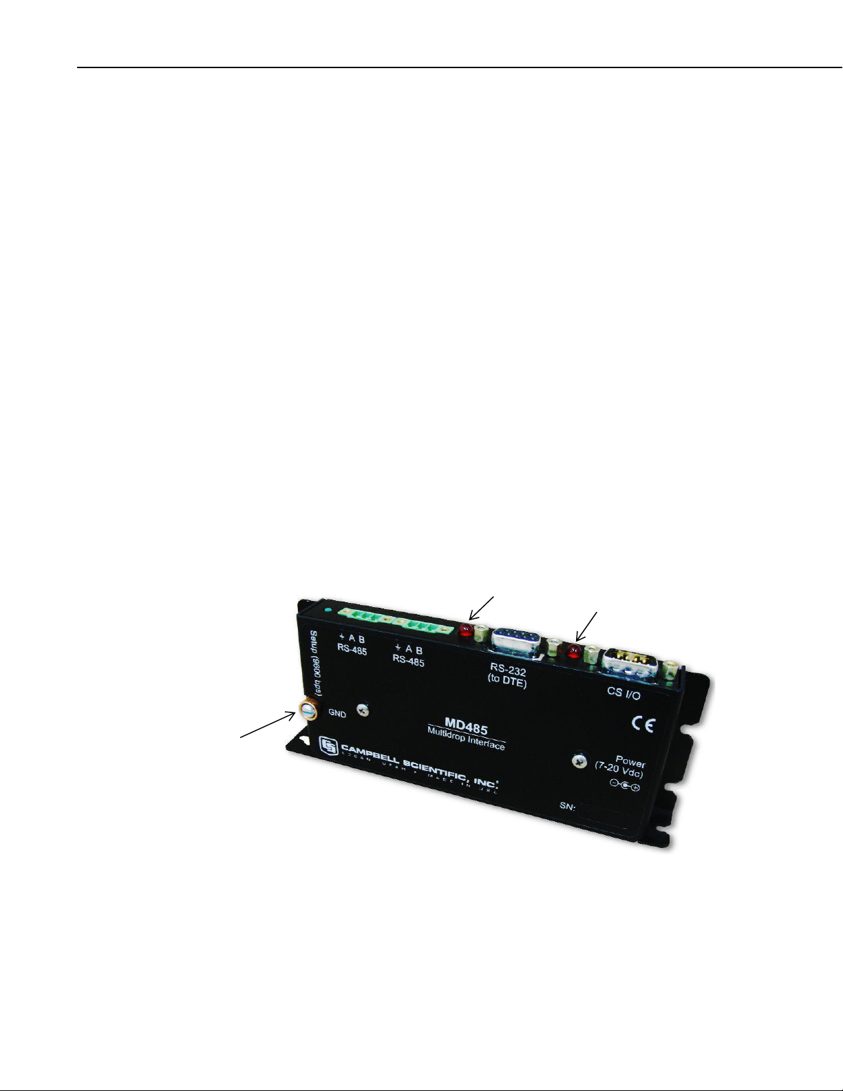
3.1.1 Ground Lug
The MD485 has a GND lug (see Figure 1). Connect this GND lug to earth
ground with 8 AWG wire. This connection should be as short as possible.
3.1.2 Indicator LEDs
The MD485 has two red LEDs. When 12V power is applied the LEDs light for
one second. The LEDs then begin flashing once every two seconds, while
there is no activity on the ports.
When the RS-485 port is an active port, the LED nearest that connector
(labeled B in Figure 1) indicates traffic on the RS-485 port, and the other LED
(labeled A) indicates traffic on the other active port (CS I/O or RS-232). When
CS I/O and RS-232 are the active ports, the LED between the CS I/O connector
and the RS-232 connector (A) indicates activity on the CS I/O port, and the
other LED (B) indicates traffic on the RS-232 port. When data is being
received and transmitted, the LEDs will flash. The LED for the port that is
transmitting will be on more than the LED for the receiving port.
GND lug
connects to
earth ground
The LED nearest the RS-485 (B) connector will blink twice a second to
indicate an RS-485 receiving error. This most likely indicates a wiring
problem between the RS-485 ports of the base and remote MD485s.
B
A
FIGURE 1. The MD485 has a ground lug that should be attached to
earth ground and LEDs that indicate traffic on the ports.
2
Page 9
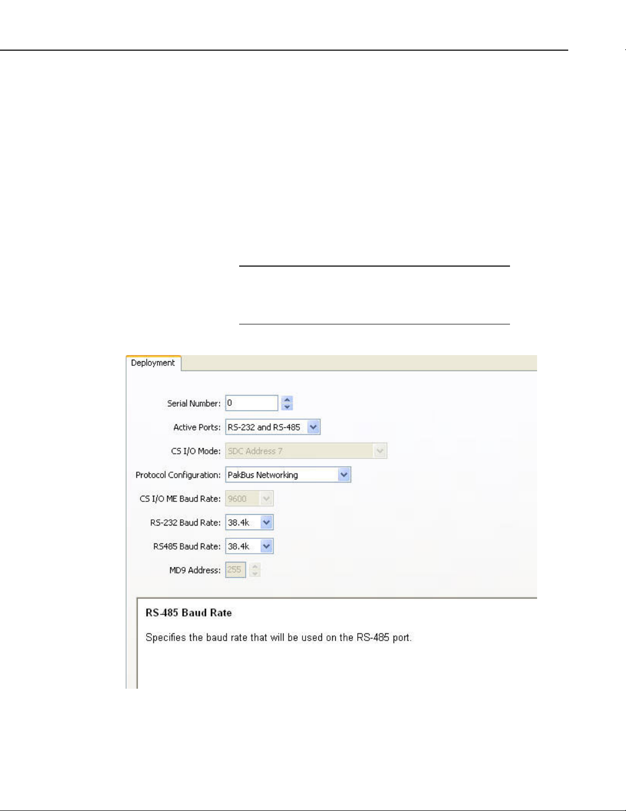
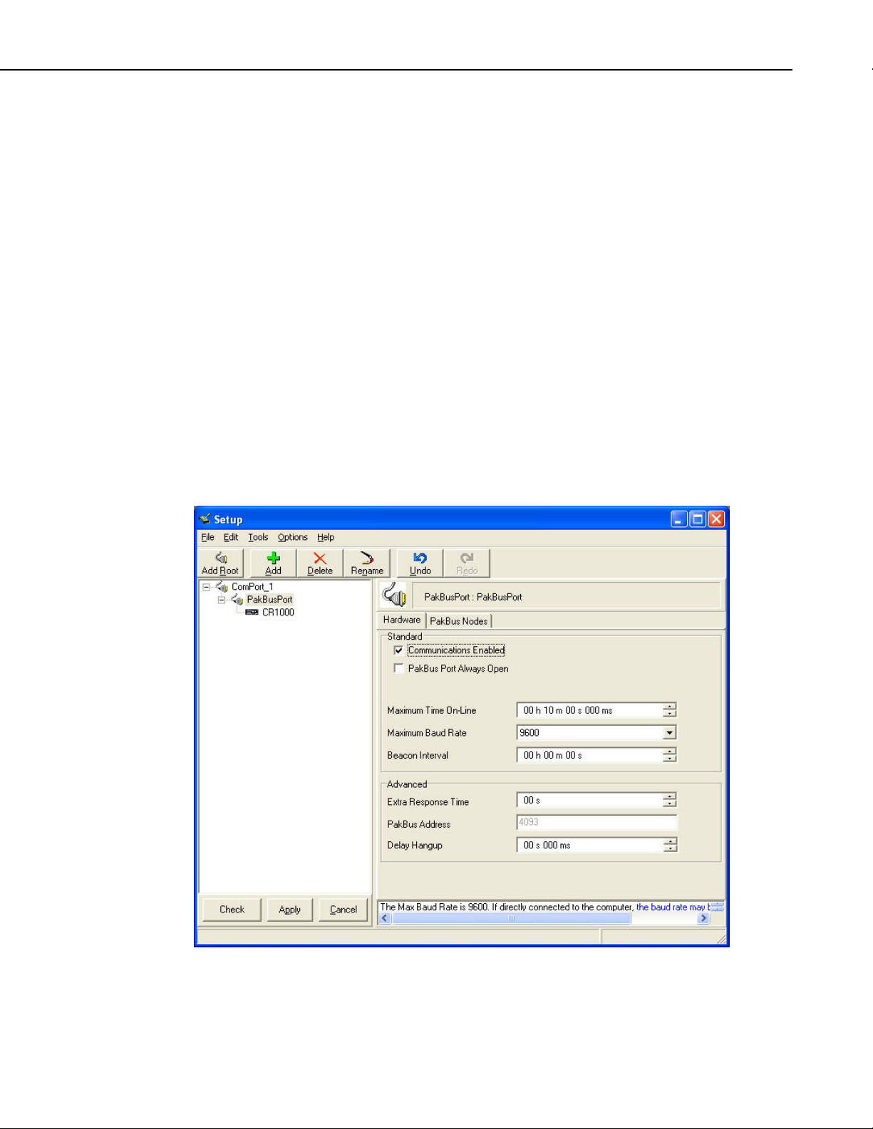
3.1.3 Configuring the MD485
The MD485 is typically configured using the Device Configuration
(DevConfig) utility, which is included with PC400 and LoggerNet and can be
downloaded at no charge from our web site. Using DevConfig, you select and
configure the active ports and choose the communication mode (see Figure 2).
Changed settings are saved in Flash memory.
MD485 RS-485 Multidrop Interface
NOTE
Alternatively, a Setup Menu can be accessed by connecting the MD485’s RS232 port to a PC running a terminal program such as Hyper Terminal
Procomm
TM
(always 9600 baud, 8-N-1) and pressing the “Setup” button on the
TM
or
MD485. Changed settings are saved in flash memory by selecting menu item
“7” as you exit the Setup Menu. If left idle, the Setup Menu will time out 2
minutes after the last received character and exit without saving any parameter
changes with the message “Setup Timeout.”
A datalogger can remain connected to the CS I/O port while
setting MD485 parameters on the RS-232 port, although CS I/O
communications would be inactive until exiting DevConfig or
the Setup Menu.
FIGURE 2. MD485 Setup using DevConfig
3
Page 10

MD485 RS-485 Multidrop Interface
NOTE
The baud rate for each port is set independently, so they can be
different. However, in some instances, mismatched baud rates
can cause an MD485 buffer overflow and create communication
failures. Regardless of the baud rates set on other interface ports,
the RS-485 ports of all MD485s in a system must be set to the
same baud rate.
3.2 Power Supplies
The typical base station MD485 connected directly to a PC uses a wall
transformer to supply 12 VDC power. You can order the optional wall
transformer (CSI Item # 15966). In a phone to MD485 base station
configuration (without datalogger) the MD485 can obtain power from a PS100
Power Supply with an A100 Null Modem Adapter. (The PS100 with an A100
attached replaces the PS512M. Either may be used whenever the PS100/A100
is referenced in this manual.)
The typical remote MD485 will be connected to a datalogger CS I/O port and
get its 12 V power from that. If your datalogger is an earlier unit without 12 V
on CS I/O pin 8 (see Table 2) or if the remote MD485 is connecting to a
datalogger RS-232 port, there is an optional Field Power Cable available (CSI
Item # 14291) with tinned leads to connect to power at the datalogger 12 V
output terminals and barrel connector to plug into the MD485’s “DC Pwr”
jack. If 120 VAC is available at the site, the wall transformer (CSI Item #
15966) is an option.
A 12 V supply may connect to either the MD485’s “DC Pwr” jack or CS I/O
pin 8 (or both, since there is diode isolation between supply inputs). The 12 V
supply inputs are diode protected against the application of reverse polarity
power.
3.3 RS-485 Cable
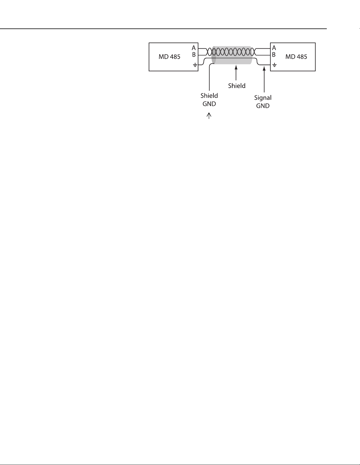
The connection between MD485s is made with the CABLE2TP-L two-twistedpair cable with shield and Santoprene jacket. Insulation colors of the twisted
pair are red/black and green/white. One pair is used for the differential data
(“A” connects to “A”; “B” connects to “B”), and one line of the other twisted
pair is used for the signal ground (third connection on the MD485 terminal
block). This is shown in Figure 3. The cable shield should be connected to a
chassis or earth ground (NOT the signal ground) at one end as shown in that
figure.
When connecting to equipment that uses “-” and “+” terminal markings, the
MD485 “A” terminal is connected to the “-” terminal and the MD485 “B”
terminal is connected to the “+” terminal.
If an application requires both the maximum distance (4000 ft) and the highest
data rate (115k) of the MD485, a better quality cable, such as a polyethylene
data cable could be used.
4
Page 11
MD485 RS-485 Multidrop Interface
3.4 Serial Cables
In an MD485 base station, a straight-through DB9M/DB9F RS-232 cable will
connect from the MD485’s RS-232 port to the PC COM port. This cable is
included with the MD485.
A remote MD485 normally uses the included SC12 cable to connect the
MD485’s CS I/O port to the datalogger’s CS I/O port.
(-)
(+)
Connect at one
end only to
chassis GND.
FIGURE 3. RS-485 Connections and Grounding
(-)
(+)
4. Quick Start
A remote MD485 can be connected to a CR200(X)-series, CR800, CR850,
CR1000, CR3000, or CR5000’s RS-232 port with a null modem DB9M/DB9M
cable (CSI Item # 18663).
This section is intended to serve as a “primer” enabling you to quickly build a
simple system and see how it operates. This section describes in five steps
how to set up a pair of MD485s in a direct connect, point-to-point network.
We recommend that you do this before undertaking field installation.
For this system you will need the following hardware or the equivalent:
1. Two MD485s
2. Transformer (Item # 15966)
3. Serial cable for PC COM port to MD485 RS-232 port (included with
MD485)
4. SC12 cable (included with MD485)
5. CSI Datalogger (such as CR1000, CR3000, CR10X, or CR23X)
6. Field Power Cable (Item # 14291) if older datalogger or wiring panel
doesn’t have 12 V on pin 8 of CS I/O port
7. CABLE2TP-L 2-twisted-pair cable with shield and Santoprene jacket
You will also need:
1. A PC with one available COM port
2. LoggerNet, PC400, or PC208W installed
5
Page 12
MD485 RS-485 Multidrop Interface
apx
TECHNOLOGIES INC.
CLASS 2 TRANSFORMER
MODEL NO: AP2105W
INPUT: 120VAC 60Hz 20W
LISTED
2H56
E144634
MADE IN CHINA
OUTPUT: 12VDC 1.0A
HICKSVILLE, NEW YORK
U
L
R
U
L
R
Step 1 – Set Up Base MD485
a. Connect serial cable from PC COM port to base MD485 RS-232 port.
b. Plug transformer into AC outlet and plug barrel connector into base
c. Using DevConfig or the MD485 setup menu as explained in Section 3.1.3,
MD485 “DC Pwr” jack. You will see both red LEDs light immediately
for 1 second. Both LEDs then begin to flash once every 2 seconds.
change the active ports of the base MD485 to “RS-232 and RS-485.” All
other options can be left in their default state.
RS-232
RS-485
PC Running
LoggerNet or PC400
FIGURE 4. MD485 Basic Point-to-Point Network
Step 2 – Set Up Remote MD485
a. Connect SC12 cable from datalogger CS I/O port to remote MD485
CS I/O port. Current datalogger/wiring panel CS I/O ports apply power to
the remote MD485.
With older dataloggers lacking 12 V on pin 8 (see Table 2), you can
power the MD485 using a Field Power Cable (see above hardware list)
between the datalogger’s 12 V (output) terminals and the MD485’s “DC
Pwr” jack.
CR10 Wiring Panels All (black, gray, silver)
PS512M Power Supply < 1712
When you connect power to the MD485 (through the SC12 cable or the
optional Field Power Cable) you should see the power-up sequence of the
red LEDs described in Step 1 (assuming datalogger is powered).
CS I/O
TABLE 2. Lacking 12 V on CS I/O Pin 8
EQUIPMENT SERIAL NUMBER
CR500 < 1765
CR7 700X Bd. < 2779
21X < 13443
6
Page 13
MD485 RS-485 Multidrop Interface
Current dataloggers and wiring panels (not mentioned in Table 2) provide
12 V on pin 8. For older products not listed, check for 12 V between
CS I/O connector pin 8 and pin 2 (GND) or contact Campbell Scientific.
b. Use default settings of MD485.
Step 3 – Connect Base MD485 to Remote MD485
a. Connect the CABLE2TP cable from the 3-pin terminal block on the Base
MD485 to the 3-pin terminal block on the Remote MD485 as described in
Section 3.3.
Step 4 – PC400/LoggerNet/PC208W Set-up
a. The next step is to run PC400/LoggerNet/PC208W and configure it to
connect to the datalogger via the MD485 point-to-point network you have
set up. The MD485 in a point-to-point network can operate transparent to
PC400/LoggerNet/PC208W. Using the EZSetup Wizard in PC400 or
LoggerNet, transparent communications is set up as if it is a direct
connect. If not using the EZSetup Wizard, simply add a datalogger to a
COM port in the Device Map.
FIGURE 5. Point-to-Point LoggerNet Network Map
7
Page 14
MD485 RS-485 Multidrop Interface
b. Set the Maximum Baud Rate for 9600 baud which is the rate at which the
MD485 communicates by default. The datalogger “Extra Response
Time” can be left at 0.
Step 5 – Connect
You are now ready to Connect to your datalogger using PC400, LoggerNet, or
PC208W Connect screen.
Datalogger program transfer and data collection are now possible.
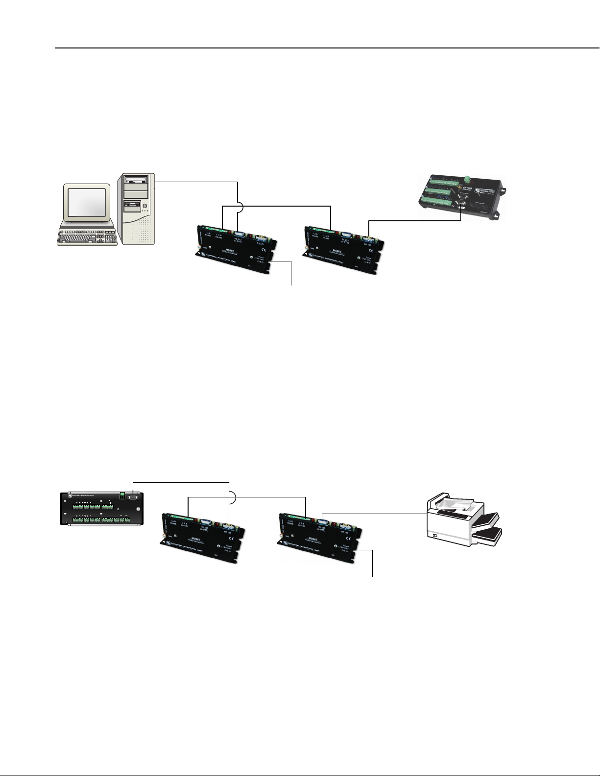
5. System Configuration
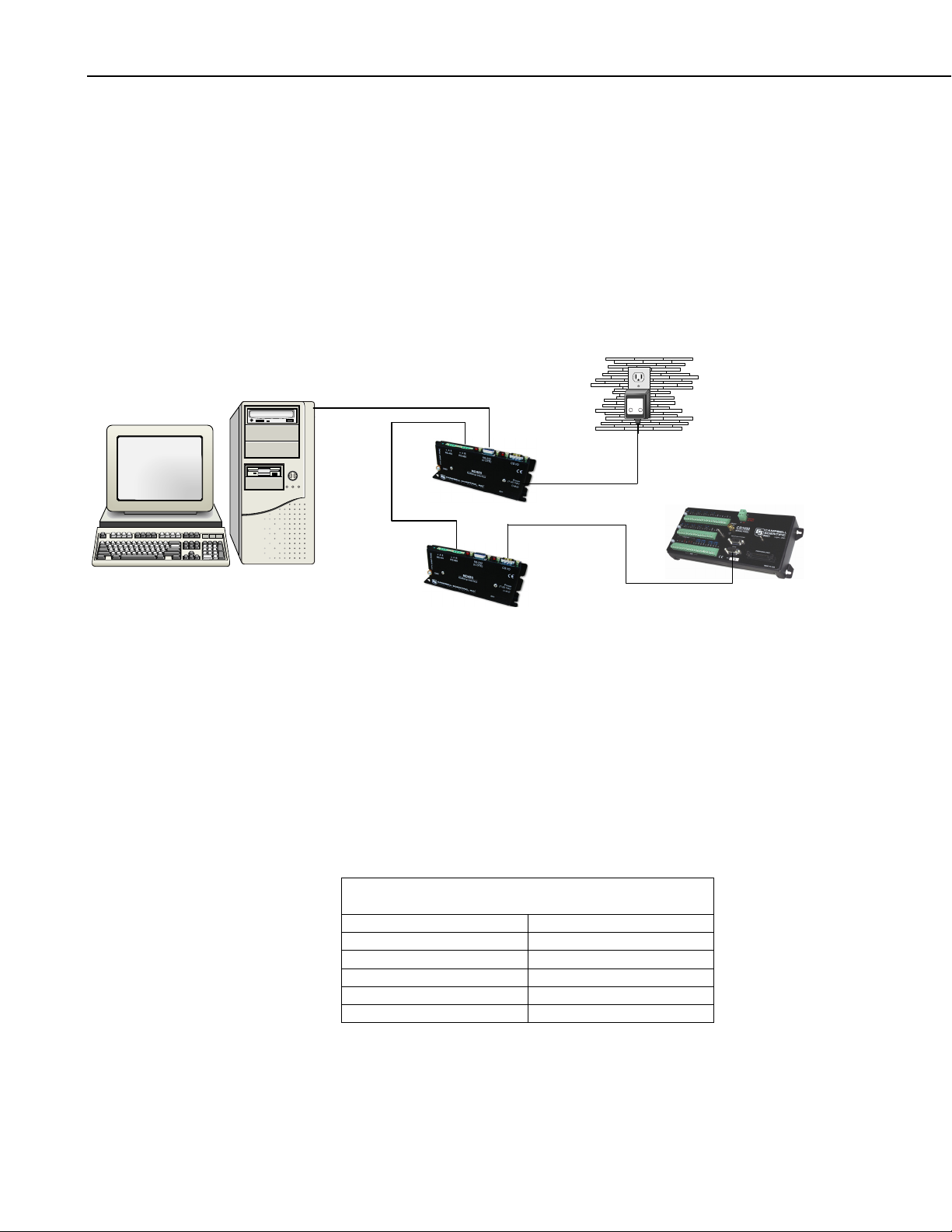
The block diagram in Figure 6 depicts the connection of a computer to a
network of Campbell Scientific dataloggers using MD485s.
RS-485
To
Wall
Transformer
RS-232
CS I/O
8
FIGURE 6. MD485 Point-to-Multipoint Network
Page 15
The base MD485 is connected to the computer's COM port with a serial cable.
A transformer supplies +12 VDC power to the MD485.
The MD485 at the computer is connected to one or more remote MD485s with
the CABLE2TP cable.
The MD485 at the datalogger is connected via an SC12 cable (supplied with
the MD485) and is powered from the datalogger CS I/O port.
Each MD485 includes (2) green 3-pin terminal blocks to allow for cable
connections.
5.1 Transparent Communication
When configured as a transparent device, the MD485 simply passes serial data
from one interface to the other as quickly as possible without translation. If
communication rates are different, the MD485 can buffer up to 1000 bytes.
Functioning as a transparent device, the MD485 becomes somewhat protocol
independent. It acts as a way to get from one physical interface to another. In
this mode the MD485 uses what is called “send-data” transmit control. The
485 transceiver is normally set to receive. When data needs to be transmitted
on the RS-485 link, the driver is enabled, and stays enabled for 1 character tone
after the last byte is sent. After this time, the transceiver switches back to
receiving.
MD485 RS-485 Multidrop Interface
When using the EZSetup Wizard provided in PC400 and LoggerNet, select
Direct Connect for the Connection Type. In transparent mode, the MD485
does not need to be represented in the network map of LoggerNet or PC208W.
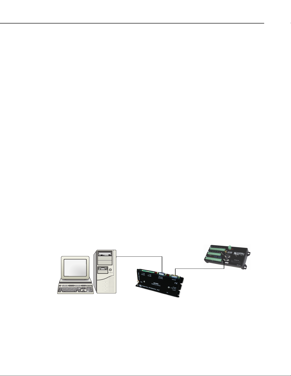
Figure 7 shows an MD485 being used as an RS-232 to CS I/O interface
converter. The MD485 is powered by the datalogger through the CS I/O
interface. RS-232 and CS I/O are chosen as the active ports in the MD485
Setup Menu. In this configuration, the MD485 acts as a full-duplex device,
fully compatible with all datalogger protocols and CS I/O configurations.
RS-232
CS I/O
FIGURE 7. RS-232 to CS I/O Conversion
Figure 8 would allow the longer distance characteristics of RS-485 to be taken
advantage of, while still providing an RS-232 interface for the PC and using
the CS I/O interface on the datalogger. A transformer is required to power the
MD485 closest to the PC. The base MD485 has RS-232 and RS-485 chosen as
9
Page 16
MD485 RS-485 Multidrop Interface
active ports, while the remote MD485 has the active ports set to RS-485 and
CS I/O. With the MD485s configured as transparent devices, the only protocol
limitation is the fact that RS-485 is a half-duplex interface. If used with
traditional datalogger communication, PC software must take the half-duplex
nature of the link into account. For array-based dataloggers, this is
accomplished by PC400, LoggerNet, or PC208W.
RS-232
RS-485
CS I/O
FIGURE 8. Long Distance RS-232 to CS I/O Conversion
Figure 9 shows how an MD485 could be used to send one-way data to a serial
printer via a P96 instruction. A null modem may be required in the RS-232
line for the printer. A transformer would be needed to power the MD485
nearest the printer, because the MD485 is not port-powered from the RS-232 or
RS-485 ports. In this configuration, the MD485 near the datalogger has CS I/O
and RS-485 as active ports. The CS I/O port should be configured to
Addressed Print Device which emulates a CSI SC99. RS-485 and RS-232 are
the active ports for the MD485 near the printer. Since printer data is one-way
only, the fact that the RS-485 interface is half-duplex is not an issue.
To Wall Transformer
10
CS I/O
Logan, Utah
78
910511 12
SE
4
6
DIFF
AG H L AGH L AGE3 AGG G
G
GHL
SE
34256
12
DIFF
3
1
G
GHL
AG H L AGH L AGE1 AGE2 G
EARTH
GROUND
G 12V
G 12V
SW 12V CTRL
POWER
SW 12V
IN
5V5V G G
CR10X WIRING PANEL
P1 GP2 G C8 C7C6 C5C4 C3 C2C1 G 12V12V
CS I/O
MADE IN USA
SDM
WIRING
PANEL NO.
RS-485
Null Modem Cable
To Wall Transformer
FIGURE 9. MD485 to Serial Printer
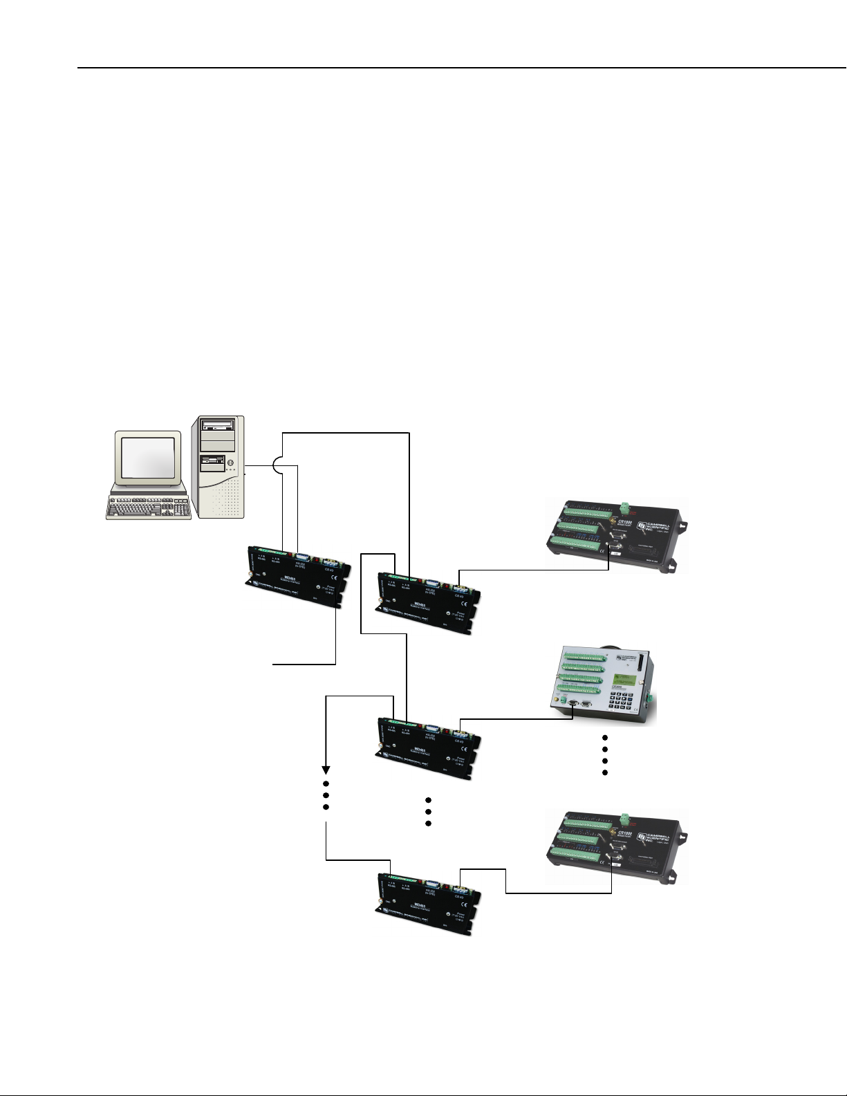
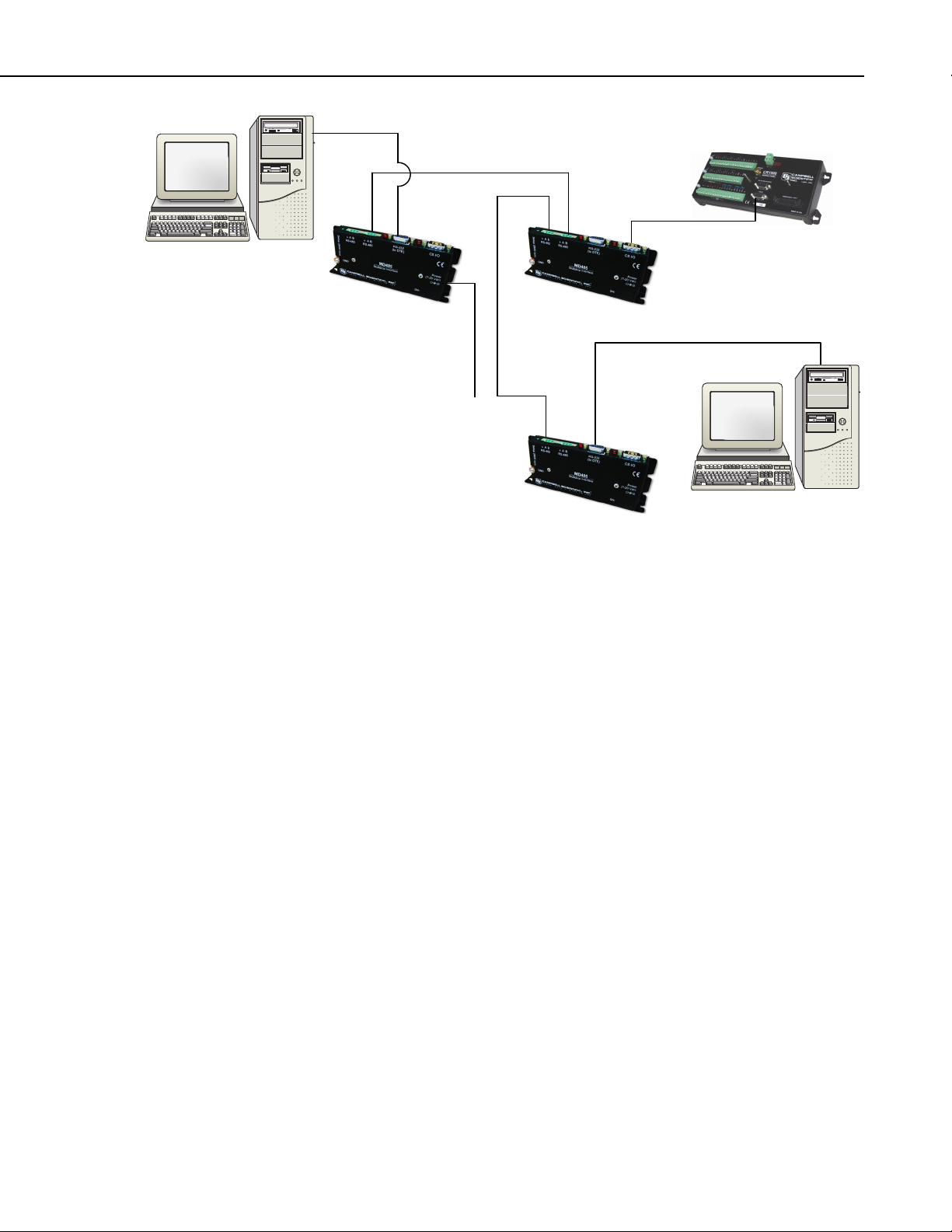
Figure 10 shows the MD485 used in a point-to-multipoint configuration. With
the MD485s in transparent mode, only a master-slave protocol is supported.
MODBUS is the only such protocol supported by CSI dataloggers and
commonly used in the SCADA industry.
Page 17
SCADA-PC
MD485 RS-485 Multidrop Interface
MODBUS
To
Wall
Transformer
FIGURE 10. Transparent Point-to-Multipoint Network
5.2 MD9 Emulation
In MD9 emulation mode, the MD485 mimics the link-oriented dialing
characteristics of the MD9. Note that the RS-485 interface is not physically
compatible with the coaxial cable used by the MD9, so an MD485 cannot be
used with an MD9. The MD9 emulation mode is not used with PakBus
dataloggers, such as the CR800, CR850, CR1000, or CR3000.
The MD485 Setup Menu is used to put the device into MD9 emulation mode.
When this option is chosen for the communication mode, an MD9 address
must also be assigned. The base MD485 should be given address 255. Remote
MD485s can be assigned addresses between 1 and 254.
In MD9 emulation mode, the MD485 looks like an MD9 to the PC, thus
allowing legacy software to use an MD485 network as if it were an MD9
network. In the LoggerNet Setup Menu, an MD9Base is inserted at the
appropriate point in the device map to represent the base MD485. Then an
MD9Remote representing each remote MD485 in the network is connected to
the MD9Base. The appropriate address for each remote MD485 must be
entered into the address field. The corresponding datalogger is then connected
to each remote in the network map.
SCADA-PC
If using PC208W, an MD9 Modem is inserted into the network map to
represent the base MD485. The remote MD485s are not shown in the network
map. Rather, the dataloggers are directly attached to the MD9 Modem. The
address of each remote MD485 is entered in the “Switch Setting of Remote
MD9” field of the corresponding datalogger.
11
Page 18

MD485 RS-485 Multidrop Interface
5.3 PakBus Networking
When configured to use PakBus protocol, the MD485 makes use of the
PakBus/Mdrop protocol on the RS-485 side. This allows reliable peer-to-peer
networking of multiple devices over the three-wire RS-485 interface.
When the communication mode is set to PakBus Networking, the MD485 does
not need to be represented in the device map of LoggerNet or PC208W. The
dataloggers are simply attached to a PakBusPort.
When using PakBus Networking, dataloggers must be set up with PakBus
addresses. They must also have beacons or neighbor filters set up as
appropriate. (Beaconing is used for most applications. Networks with RF401s
use neighbor filters.)
In PakBus Networking mode, datalogger-to-datalogger communication is
possible.
6. Combining with Other Devices
Besides the “direct” to PC communications described in the Quick Start and
System Configuration sections, it is possible to combine methods in datalogger
communications.
NOTE
When using the MD9 emulation, PC400 software does not
support these combined communication options; use either
LoggerNet or PC208W software.
Some combined communications examples:
1) Phone to MD485: PC to external modem to COM220 to PS100 with A100
to MD485 to MD485 to datalogger (see Appendix A)
2) RF401 to MD485: PC to RF401s then through null modem cable (or
PS100 with A100) to MD485s to datalogger (see Appendix B)
3) MD485 to RF401: PC to MD485s then through null modem cable (or
PS100 with A100) to RF401s to datalogger (see Appendix C)
4) Cellular Digital Modem to MD485: PC to modem to Cellular Digital
Modem then through null modem cable to MD485 to MD485 to
datalogger (see Appendix D)
5) Network to MD485: PC to Internet to NL100 to MD485 to datalogger
(use LoggerNet IPPort or PC208W socket, remote IP address, port
number, see Appendix E)
The MD485 can also be used with the CC640 digital camera and the AVW200
Vibrating Wire Interface. When used with the CC640, the MD485 allows the
distance between the camera and a PakBus datalogger to exceed 25 feet (see
Appendix F). It is desirable to use the MD485 with an AVW200 for locations
where wireless communication is impractical, but the distance between
AVW200 interfaces needs to be extended (see Appendix G).
12
Page 19

7. Call-back
Datalogger initiated communication, commonly referred to as “call-back,” is
possible through MD485s in transparent mode. In order to do call-back,
LoggerNet Setup, MD485 Configuration and Hardware should be done as
described in the Transparent Communication section of Appendix A with two
changes in the LoggerNet Setup. The ComPort must have “Call-back Enabled”
checked and the datalogger must have the “Call-back ID” entered to match the
Call-back ID in the P97 instruction of the Edlog program.
For information on how to program the datalogger for call-back, see the
appendix covering Call-back or Datalogger Initiated Communication in the
datalogger manual.
8. Wiring Specifications
8.1 RS-485 Line Length
The EIA/TIA RS-485 communications standard, an upgrade of RS-422,
supports 32 devices (driver/receiver pairs) in a party line or multi-drop mode,
on a cable of up to 4,000 feet.
MD485 RS-485 Multidrop Interface
8.2 Grounding
The standard specifies that each device has a “unit load” of not more than 12k
ohm. It does not specify cable type or data rate.
The MD485 has a 1/8-unit-load receiver input impedance (96k ohm) that
allows up to 256 transceivers on the bus. Practical network design will be more
of a limitation than the electrical load limit of 256 nodes for the MD485.
The RS-485 data transceivers used in the MD485 feature fail-safe circuitry,
which guarantees a logic-high receiver output when the receiver inputs are
open or shorted. Because of this no “biasing resistors” need to be used. They
also feature reduced slew-rate drivers that minimize EMI and reduce
reflections. Because of this, termination resistors do not need to be used for
most applications.
The MD485 has a ground lug. Connect this ground lug to earth ground with an
8 AWG wire. This connection should be as short as possible.
The differential signaling of RS-485 does not require a signal ground to
communicate. The standard allows for a common-mode voltage (Vcm) of -7 to
+12 V. As long as the MD485 local grounds do not exceed this common-mode
voltage limit, the RS-485 communication will work fine.
Over a distance of hundreds or thousand of feet, there can be significant
differences in the voltage level of “ground”; it can easily extend beyond the
common-mode voltage limits of RS-485. The signal ground wire serves to tie
the signal ground of each node to one common ground, which is within the
common-mode voltage of the RS-485 specification.
13
Page 20

MD485 RS-485 Multidrop Interface
The RS-485 specification also recommends connecting a 100 ohm resistor of at
least 0.5 W in series between each node’s signal ground and the network’s
ground wire. This resistor is in the MD485, between the terminal block
connection marked with the ground symbol and the MD485 power ground.
This way, if the ground potentials of two nodes vary, the resistors limit the
current in the ground wire.
See Figure 1, Figure 3, and Section 3.3 for more information on ground
connections.
8.3 Protection and Isolation
The MD485 incorporates gas tubes and multilayer varistors on the RS-485 port
for protection against ESD and surge. The MD485 passes IEC61000-4-2, test
level 4 for both contact and air discharge. It also passes IEC61000-4-5, test
level 3 for surge immunity.
If large ground potentials exist, optical isolation may be desired. One
recommended optical isolator is B&B’s Model 485OP, which provides 2 kV
isolation. If most of the nodes in the network close together (limited ground
differences), and one node is located at a distance (large ground difference),
then a single optical isolator can be located on the distant node. If all of the
nodes are distant from each other, optical isolation will be needed at every
node.
8.4 Termination
8.5 Summary
The Model 485OP can also be used as a repeater to extend the network.
The RS-485 spec says to use termination. For high baud rates (>115k) and long
cable runs, this is true.
In most equipment though, with maximum speeds of 115 kbit, it is
unnecessary. Adding termination dramatically increases power consumption,
and complicates system design. It rarely solves problems when used in the
kilobit data range.
If power is not a concern, and signal integrity is questioned, the network can be
terminated with a 120 ohm resistor at the extreme ends of the line. There
should be no more than two terminations in a system that does not use
repeaters.
• Use CABLE2TP-L 2-twisted-pair cable with shield and Santoprene jacket
for most installations.
• Connect the MD485’s ground lug to earth ground with an 8 AWG wire.
This connection should be as short as possible.
14
• Connect the “signal ground” wire between MD485s.
• Ground the shield at one end only (to earth ground).
Page 21

MD485 RS-485 Multidrop Interface
• In most instances, no termination is required.
• If large ground potentials exist, use optical isolation. (B&B’s Model
4850P)
• Electrically, 256 MD485s can be connected, but that may be an
unmanageable network.
15
Page 22

MD485 RS-485 Multidrop Interface
16
Page 23
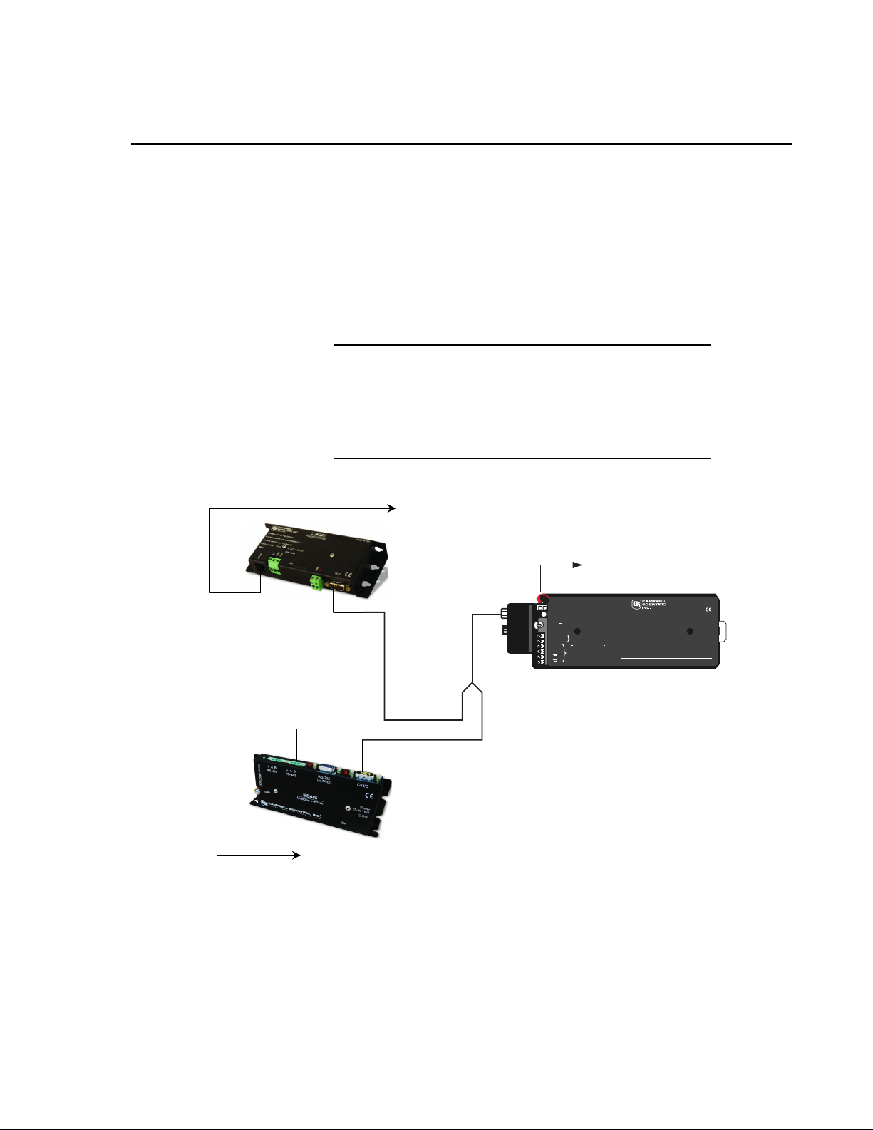
Appendix A. Phone to MD485 Network
It is possible to access an MD485 network via telephone when the network is
miles from the PC. See Figure A-1.
A Campbell Scientific Model COM220 Telephone Modem is used in
conjunction with a Model PS100 Power Supply and A100 Null Modem
Adapter to communicate with an MD485. The COM220 and the MD485 are
both supplied with a 9 pin SC12 cable suitable for connection to the A100.
The PS100 provides 5 and 12 volts for system operation and the A100
performs the function of a null modem (the COM220 and MD485 are both
"modem" devices).
NOTE
The telephone to MD485 Network using a PS100 with A100
may be done with Transparent Communication or MD9
Emulation, but is not possible with PakBus Networking.
Connection to a single PakBus Datalogger is still possible with
Transparent Communication. PakBus Networking can be done
by using a datalogger in place of the PS100/A100 for routing.
To Phone Line
To Wall
Transformer
or
Solar Panel
MADE IN USA
Logan, Utah
LIFT TO
REMOVE
A100
Adapter
Null Modem Port
BATTERY
- INTERNAL (12V 7 AMP HOUR)
- EXTERNAL RECHARGEABLE BATTERY
BATTERY
CHARGE
- CHARGING VOLTAGE PRESENT
OFF ON
- POWER TO 12V TERMINALS
CHARGE
FROM CHARGER OR SOLAR PANEL
CHARGE
16-28VDC OR 18VAC RMS
+12V
TO EITHER TERMINAL, TO OTHER
+12V
POWER TO DATALOGGERS
OR 12V PERIPHERALS
WARNING:
PERMANENT DAMAGE TO
RECHARGEABLE CELLS MAY
RESULT IF DISCHARGED
BELOW 10.5 VOLTS
PS100 12V POWER SUPPLY
WITH CHARGING REGULATOR
The A100 Null Modem
Adapter has two 9-pin
connectors. The SC12
cable from the COM220
is connected to either
connector and the SC12
from the MD485 is
connected to the other.
To RS-485 Network
FIGURE A-1. Telephone to MD485 Conversion
Where a phone to MD485 Base is desired, the following configurations will
provide Point-to-Point or Point-to-Multipoint communications.
A-1
Page 24

Appendix A. Phone to MD485 Network
1. HARDWARE REQUIREMENTS
a. MD485s
b. COM220
c. PS100 with A100
d. Transformer (CSI Item # 9591) or solar panel
e. Three SC12 cables (one included with each MD485 and one with
f. CABLE2TP cable
2. TRANSPARENT COMMUNICATION (POINT-TO-POINT)
PC-Modem----COM220-PS100 with A100-MD485---MD485-DL
LoggerNet Setup
a. Setup:
ComPort_1
PhoneBase
PhoneRemote
PakBus Port (PakBus dataloggers only)
CR1000
COM220)
b. ComPort_1 – default settings
c. PhoneBase
1) Modem Type – specify PC's phone modem
2) Maximum Baud Rate – 9600
3) Extra Response Time – 0 s
d. PhoneRemote – input base site’s phone number
e. PakBus Port – defaults
f. CR1000 – default settings, schedule collections as desired
MD485 Configuration
a. Base MD485
1) Active Ports – “CS I/O and RS-485”
2) Communication Mode – “Transparent Communication”
3) CS I/O Port Configuration – “Modem to Modem w/o
Datalogger”
4) RS-485 Port Configuration – Desired baud rate
b. Remote MD485
A-2
1) Active Ports – “CS I/O and RS-485”
2) Communication Mode – “Transparent Communication”
3) CS I/O Port Configuration – Modem Enable
4) RS-485 Port Configuration – Desired baud rate
Page 25

Appendix A. Phone to MD485 Network
3. MD9 EMULATION (POINT-TO-MULTIPOINT)
PC-Modem ----COM220-PS100 with A100-MD485 ----------MD485-DL1
----------MD485-DL2
LoggerNet Setup
a. Setup:
ComPort_1
PhoneBase
PhoneRemote
MD9Base
MD9Remote
CR10X
MD9Remote_2
CR10X_2
b. ComPort_1 – default settings
c. PhoneBase
1) Modem Type – specify PC's phone modem
2) Maximum Baud Rate – 9600
3) Extra Response Time – 0 s
d. PhoneRemote – input base site’s phone number
e. MD9Base – defaults
f. MD9Remote – Address: “1“
g. MD9Remote_2 – Address: “2“
h. Dataloggers – default settings, schedule collections as desired
A-3
Page 26

Appendix A. Phone to MD485 Network
FIGURE A-2. LoggerNet Phone to MD485 MD9 Emulation Setup
MD485 Configuration
a. Base MD485
1) Active Ports – “CS I/O and RS-485”
2) Communication Mode – “MD9 Emulation” with address 255
3) CS I/O Port Configuration – “Modem to Modem w/o
Datalogger”
4) RS-485 Port Configuration – Desired baud rate
b. Remote MD485s
1) Active Ports – “CS I/O and RS-485”
2) Communication Mode – “MD9 Emulation” with address 1, 2,
etc. (unique for each remote MD485 and must agree with
respective MD9 in device map)
3) CS I/O Port Configuration – Modem Enable
4) RS-485 Port Configuration – Desired baud rate
4. HARDWARE
A-4
After configuring LoggerNet or PC208W and the MD485s you are ready
to set up hardware. The A100 null modem connectors (it’s not important
which connector goes to which unit) connect via SC12 cables to the
Page 27

Appendix A. Phone to MD485 Network
COM220 and the base MD485 CS I/O port. Connect the site phone line
to COM220. Connect power to PS100. When you turn on the PS100
supply, the MD485 receives 12V power and you will see the LEDs light
in their power-up sequence.
Remote MD485s normally connect to datalogger CS I/O ports via SC12
cables. Powering up the datalogger will start the MD485 operating.
Connect the CABLE2TP cable between the RS-485 ports of the base and
remote MD485s and you are ready to connect to the datalogger.
A-5
Page 28

Appendix A. Phone to MD485 Network
This is a blank page.
A-6
Page 29

Appendix B. RF401 to MD485 Network
Where an RF401 to MD485 network is desired, the following configurations
will provide access to an MD485 network via RF401s.
The connection between the remote RF401 and the base MD485 can be made
in two different ways. 1) Using a Campbell Scientific PS100 Power Supply
with A100 Null Modem Adapter. The PS100 provides 5 and 12 volts for
system operation and the A100 performs the function of a null modem (the
RF401 and MD485 are both "modem" devices). 2) Usin g a null modem cable
and transformers to provide power to the RF401 and the MD485.
The following sections will describe how to set-up the RF401 to MD485
network using each of these two methods for each communication mode.
B.1 Connection using a PS100 with A100
Figure B-1 shows an RF401 to MD485 network using a PS100 with A100.
The following configurations will provide communications in transparent mode
or with MD9 emulation. Connection to a single PakBus datalogger is possible
with transparent communication. PakBus Networking is not possible using the
PS100/A100, but can be done using a datalogger in place of the PS100/A100
for routing.
RS-232
Power
To Wall Transformer
CS I/O
A100
Null Modem Port
- INTERNAL (12V 7 AMP HOUR)
BATTERY
- EXTERNAL RECHARGEABLE BATTERY
BATTERY
CHARGE
- CHARGING VOLTAGE PRESENT
OFF ON
- POWER TO 12V TERMINALS
CHARGE
Adapter
FROM CHARGER OR SOLAR PANEL
CHARGE
16-28VDC OR 18VAC RMS
TO EITHER TERMINAL, TO OTHER
+12V
+12V
POWER TO DATALOGGERS
OR 12V PERIPHERALS
CS I/O
RS-485
CS I/O
FIGURE B-1. RF401 to MD485 Conversion
MADE IN USA
Logan, Utah
WARNING:
PERMANENT DAMAGE TO
RECHARGEABLE CELLS MAY
RESULT IF DISCHARGED
BELOW 10.5 VOLTS
PS100 12V POWER SUPPLY
WITH CHARGING REGULATOR
LIFT TO
REMOVE
B-1
Page 30

Appendix B. RF401 to MD485 Network
1. HARDWARE REQUIREMENTS
a. MD485s
b. RF401s
c. PS100 with A100
d. Transformer (CSI Item #15966) for base RF401
e. Transformer (CSI Item # 9591) or solar panel for PS100
f. Three SC12 cables (one included with each MD485 and one with
g. CABLE2TP
2. TRANSPARENT COMMUNICATION (POINT-TO-POINT)
PC-RF401----RF401-PS100 with A100-MD485---MD485-DL
LoggerNet Setup
a. Setup:
ComPort_1
PakBus Port (PakBus dataloggers only)
CR1000
RF401)
b. ComPort_1 – default settings
c. PakBus Port – defaults (PakBus dataloggers only)
d. CR1000 – default settings, schedule collections as desired
MD485 Configuration
a. Base MD485
1) Active Ports – “CS I/O and RS-485”
2) Communication Mode – “Transparent Communication”
3) CS I/O Port Configuration – “Modem to Modem w/o
Datalogger”
4) RS-485 Port Configuration – Desired baud rate
b. Remote MD485
1) Active Ports – “CS I/O and RS-485”
2) Communication Mode – “Transparent Communication”
3) CS I/O Port Configuration – Modem Enable
4) RS-485 Port Configuration – Desired baud rate
RF401 Configuration
B-2
The RF401s may be left in their default settings. However, if there is a
neighboring RF401 network, you should change the Hopping Sequence of
base and remote RF401s to a new setting to avoid interference.
Page 31

Appendix B. RF401 to MD485 Network
3. MD9 EMULATION (POINT-TO-MULTIPOINT)
PC-RF401 ----RF401-PS100 with A100-MD485 ----------MD485-DL1
----------MD485-DL2
LoggerNet Setup
a. Setup:
ComPort_1
MD9Base
MD9Remote
CR10X
MD9Remote_2
CR10X_2
b. ComPort_1 – default settings
c. MD9Base – defaults
d. MD9Remote – Address: “1“
e. MD9Remote_2 – Address: “2“
f. Dataloggers – default settings, schedule collections as desired
FIGURE B-2. LoggerNet RF401 to MD485 MD9 Emulation Setup
B-3
Page 32

Appendix B. RF401 to MD485 Network
MD485 Configuration
a. Base MD485
b. Remote MD485s
RF401 Configuration
The RF401s may be left in their default settings. However, if there is a
neighboring RF401 network, you should change the Hopping Sequence of
base and remote RF401s to a new setting to avoid interference.
1) Active Ports – “CS I/O and RS-485”
2) Communication Mode – “MD9 Emulation” with address 255
3) CS I/O Port Configuration – “Modem to Modem w/o Datalogger”
4) RS-485 Port Configuration – Desired baud rate
1) Active Ports – “CS I/O and RS-485”
2) Communication Mode – “MD9 Emulation” with address 1, 2,
etc. (unique for each remote MD485 and must agree with
respective MD9 in device map)
3) CS I/O Port Configuration – Modem Enable
4) RS-485 Port Configuration – Desired baud rate
4. HARDWARE
After configuring LoggerNet or PC208W, the RF401s and the MD485s
you are ready to set up hardware. Connect the base RF401 RS-232 port to
the PC COM port. The A100 null modem connectors (it’s not important
which connector goes to which unit) connect via SC12 cables to the CS
I/O ports of the remote RF401 and the base MD485. Connect power to
the PS100. When you turn on the PS100 supply, the MD485 receives
12V power and you will see the LEDs light in their power-up sequence.
Remote MD485s normally connect to datalogger CS I/O ports via SC12
cables. Powering up the datalogger will start the MD485 operating.
Connect the CABLE2TP cable between the RS-485 ports of the base and
remote MD485s and you are ready to connect to the datalogger.
B.2 Connection using a Null Modem Cable
The RF401 to MD485 conversion can be done using a null modem cable in
place of the PS100/A100. The following configurations will provide
communications in transparent mode, MD9 Emulation or PakBus Networking.
1. HARDWARE REQUIREMENTS
a. MD485s
b. RF401s
c. Three transformers (CSI Item #15966)
d. Null modem cable (CSI Item #18663)
e. Three SC12 cables (one included with each MD485 and one with
RF401)
f. CABLE2TP
B-4
Page 33

Appendix B. RF401 to MD485 Network
2. TRANSPARENT COMMUNICATION (POINT-TO-POINT)
PC-RF401----RF401--null modem--MD485---MD485-DL
LoggerNet Setup
a. Setup:
ComPort_1
PakBus Port (PakBus dataloggers only)
CR1000
b. ComPort_1 – default settings
c. PakBus Port – defaults (PakBus dataloggers only)
d. CR1000 – corresponding PakBus address (PakBus dataloggers
only), other settings default, schedule collections as desired
MD485 Configuration
a. Base MD485
1) Active Ports – “RS-232 and RS-485”
2) Communication Mode – “Transparent Communication”
3) RS-232 Port Configuration – Desired baud rate
4) RS-485 Port Configuration – Desired baud rate
b. Remote MD485
1) Active Ports – “CS I/O and RS-485”
2) Communication Mode – “Transparent Communication”
3) CS I/O Port Configuration – Modem Enable
4) RS-485 Port Configuration – Desired baud rate
RF401 Configuration
The RF401s may be left in their default settings. However, if there is a
neighboring RF401 network, you should change the Hopping Sequence of
base and remote RF401s to a new setting to avoid interference.
3. MD9 EMULATION (POINT-TO-MULTIPOINT)
PC-RF401 ----RF401--null modem---MD485 ----------MD485-DL1
-----------MD485-DL2
LoggerNet Setup
a. Setup:
ComPort_1
MD9Base
MD9Remote
CR23X
MD9Remote_2
CR23X_2
B-5
Page 34

Appendix B. RF401 to MD485 Network
b. ComPort_1 – default settings
c. MD9Base – defaults
d. MD9Remote – Address: “1“
e. MD9Remote_2 – Address: “2“
f. Dataloggers – default settings, schedule collections as desired
MD485 Configuration
a. Base MD485
b. Remote MD485s
1) Active Ports – “RS-232 and RS-485”
2) Communication Mode – “MD9 Emulation” with address 255
3) RS-232 Port Configuration – Desired baud rate
4) RS-485 Port Configuration – Desired baud rate
1) Active Ports – “CS I/O and RS-485”
2) Communication Mode – “MD9 Emulation” with address 1, 2,
etc. (unique for each remote MD485 and must agree with
respective MD9 in device map)
3) CS I/O Port Configuration – Modem Enable
4) RS-485 Port Configuration – Desired baud rate
RF401 Configuration
The RF401s may be left in their default settings. However, if there is a
neighboring RF401 network, you should change the Hopping Sequence of
base and remote RF401s to a new setting to avoid interference.
4. PAKBUS NETWORKING
PC-RF401 ----RF401--null modem---MD485 ----------MD485-DL1
-----------MD485-DL2
LoggerNet Setup
a. Setup:
ComPort_1
PakBus Port
CR1000
CR1000_2
b. ComPort_1 – default settings
c. PakBus Port – defaults
d. Dataloggers – corresponding PakBus address, other setting default,
schedule collections as desired
B-6
Page 35

Appendix B. RF401 to MD485 Network
FIGURE B-3. LoggerNet PakBus Networking Setup
MD485 Configuration
a. Base MD485
1) Active Ports – “RS-232 and RS-485”
2) Communication Mode – “PakBus Networking”
3) RS-232 Port Configuration – Desired baud rate
4) RS-485 Port Configuration – Desired baud rate
b. Remote MD485s
1) Active Ports – “CS I/O and RS-485”
2) Communication Mode – “PakBus Networking”
3) CS I/O Port Configuration – SDC Address 7 or SDC Address 8
4) RS-485 Port Configuration – Desired baud rate
RF401 Configuration
The RF401s may be left in their default settings. However, if there is a
neighboring RF401 network, you should change the Hopping Sequence of
base and remote RF401s to a new setting to avoid interference.
B-7
Page 36

Appendix B. RF401 to MD485 Network
5. HARDWARE
After configuring LoggerNet or PC208W, the RF401s and the MD485s
you are ready to set up hardware. Connect the base RF401 RS-232 port to
the PC COM port. Attach the null modem cable to the RS-232 ports of
the remote RF401 and the base MD485. Attach transformers to the DC
Pwr jack of each RF401 and the base MD485.
Remote MD485s normally connect to datalogger CS I/O ports via SC12
cables. Powering up the datalogger will start the MD485 operating.
Connect the CABLE2TP cable between the RS-485 ports of the base and
remote MD485s and you are ready to connect to the datalogger.
B-8
Page 37

Appendix C. MD485 to RF401 Network
+12V
PS100 12V POWER SUPPLY
A100
Null Modem Port
Adapter
WITH CHARGING REGULATOR
MADE IN USA
WARNING:
PERMANENT DAMAGE TO
RECHARGEABLE CELLS MAY
RESULT IF DISCHARGED
BELOW 10.5 VOLTS
+12V
BATTERY
- INTERNAL (12V 7 AMP HOUR)
LIFT TO
REMOVE
BATTERY
- EXTERNAL RECHARGEABLE BATTERY
CHARGE
- CHARGING VOLTAGE PRESENT
OFF ON
- POWER TO 12V TERMINALS
CHARGE
CHARGE
FROM CHARGER OR SOLAR PANEL
16-28VDC OR 18VAC RMS
TO EITHER TERMINAL, TO OTHER
POWER TO DATALOGGERS
OR 12V PERIPHERALS
Logan, Utah
Where an MD485 to RF401 network is desired, the following configurations
will provide access to an RF401 network via MD485s.
The connection between the remote MD485 and the base RF401 can be made
in two different ways. 1) Using a Campbell Scientific PS100 Power Supply
with A100 Null Modem Adapter. The PS100 provides 5 and 12 volts for
system operation and the A100 performs the function of a null modem (the
RF401 and MD485 are both "modem" devices). 2) Using a null modem cable
and transformers to provide power to the RF401 and the MD485.
The following sections will describe how to set-up the MD485 to RF401
network using each of these two methods for each communication mode.
C.1 Connection using a PS100 with A100
Figure C-1 shows an MD485 to RF401 network using a PS100 with A100.
The following configurations will provide communications in transparent mode
or with MD9 emulation. Connection to a single PakBus datalogger is possible
with transparent communication. PakBus Networking is not possible using the
PS100/A100, but can be done using a datalogger in place of the PS100/A100
for routing.
RS-232
RS-485
To Wall Transformer
To
Wall
Transformer
CS I/O
CS I/O
CS I/O
FIGURE C-1. MD485 to RF401 Conversion
C-1
Page 38

Appendix C. MD485 to RF401 Network
1. HARDWARE REQUIREMENTS
a. MD485s
b. RF401s
c. PS100 with A100
d. Transformer (CSI Item #15966) for base MD485
e. Transformer (CSI Item # 9591) or solar panel for PS100
f. Three SC12 cables (one included with MD485 and one with each
g. CABLE2TP cable
2. TRANSPARENT COMMUNICATION (POINT-TO-POINT)
PC-MD485----MD485-PS100 with A100-RF401---RF401-DL
LoggerNet Setup
a. Setup:
RF401)
ComPort_1
PakBus Port (PakBus dataloggers only)
CR1000
b. ComPort_1 – default settings
c. PakBus Port – defaults (PakBus dataloggers only)
d. CR1000 – default settings, schedule collections as desired
MD485 Configuration
a. Base MD485
1) Active Ports – “RS-232 and RS-485”
2) Communication Mode – “Transparent Communication”
3) RS-232 Port Configuration – Desired baud rate
4) RS-485 Port Configuration – Desired baud rate
b. Remote MD485
1) Active Ports – “CS I/O and RS-485”
2) Communication Mode – “Transparent Communication”
3) CS I/O Port Configuration – Modem Enable
4) RS-485 Port Configuration – Desired baud rate
RF401 Configuration
The active interface of the base RF401 should be set to “COM2xx to
RF401”. All other RF401 settings maybe left in their default state.
However, if there is a neighboring RF401 network, you should change the
Hopping Sequence of base and remote RF401s to a new setting to avoid
interference.
C-2
Page 39

3. MD9 EMULATION
Appendix C. MD485 to RF401 Network
PC-MD485----MD485-PS100 with A100-RF401---RF401-DL
LoggerNet Setup
a. Setup:
ComPort_1
MD9Base
MD9Remote
CR10X
b. ComPort_1 – default settings
c. MD9Base – defaults
d. MD9Remote – Address: “1“
e. Datalogger – default settings, schedule collections as desired
MD485 Configuration
a. Base MD485
1) Active Ports – “RS-232 and RS-485”
2) Communication Mode – “MD9 Emulation” with address 255
3) RS-232 Port Configuration – Desired baud rate
4) RS-485 Port Configuration – Desired baud rate
b. Remote MD485
1) Active Ports – “CS I/O and RS-485”
2) Communication Mode – “MD9 Emulation” with address 1, 2,
etc. (unique for each remote MD485 and must agree with
respective MD9 in device map)
3) CS I/O Port Configuration – Modem Enable
4) RS-485 Port Configuration – Desired baud rate
RF401 Configuration
The active interface of the base RF401 should be set to “COM2xx to
RF401”. All other RF401 settings maybe left in their default state.
However, if there is a neighboring RF401 network, you should change the
Hopping Sequence of base and remote RF401s to a new setting to avoid
interference.
4. HARDWARE
After configuring LoggerNet or PC208W, the RF401s and the MD485s
you are ready to set up hardware. Connect the base MD485 RS-232 port
to the PC COM port. Attach a transformer to the DC Pwr jack of the base
MD485. The A100 null modem connectors (it’s not important which
connector goes to which unit) connect via SC12 cables to the CS I/O ports
of the remote MD485 and the base RF401. Connect power to the PS100.
C-3
Page 40

Appendix C. MD485 to RF401 Network
When you turn on the PS100 supply, the MD485 and the RF401 receive
12V power and you will see the LEDs light in their power-up sequence.
The remote RF401 connects to datalogger CS I/O port via an SC12 cable.
Powering up the datalogger will start the RF401 operating.
Connect the two twisted pair, shielded cable between the RS-485 ports of
the base and remote MD485s and you are ready to connect to the
datalogger.
C.2 Connection using a Null Modem Cable
The MD485 to RF401 conversion can be done using a null modem cable in
place of the PS100/A100. The following configurations will provide
communications in transparent mode, MD9 Emulation or PakBus Networking.
1. HARDWARE REQUIREMENTS
a. MD485s
b. RF401s
c. Three transformers (CSI Item #15966)
d. Null modem cable (CSI Item #18663)
e. Three SC12 cables (one included with each RF401 and one with
MD485)
f. CABLE2TP cable
2. TRANSPARENT COMMUNICATION (POINT-TO-POINT)
PC-MD485----MD485--null modem--RF401---RF401-DL
LoggerNet Setup
a. Setup:
ComPort_1
PakBus Port (PakBus dataloggers only)
CR1000
b. ComPort_1 – default settings
c. PakBus Port – defaults (PakBus dataloggers only)
d. CR1000 – default settings, schedule collections as desired
MD485 Configuration
a. Base MD485
1) Active Ports – “RS-232 and RS-485”
2) Communication Mode – “Transparent Communication”
3) RS-232 Port Configuration – Desired baud rate
4) RS-485 Port Configuration – Desired baud rate
C-4
Page 41

Appendix C. MD485 to RF401 Network
b. Remote MD485
1) Active Ports – “RS-232 and RS-485”
2) Communication Mode – “Transparent Communication”
3) RS-232 Port Configuration – Desired baud rate
4) RS-485 Port Configuration – Desired baud rate
RF401 Configuration
The RF401s may be left in their default settings. However, if there is a
neighboring RF401 network, you should change the Hopping Sequence of
base and remote RF401s to a new setting to avoid interference.
3. MD9 EMULATION (POINT-TO-MULTIPOINT)
PC-MD485----MD485--null modem---RF401--RF401-DL
LoggerNet Setup
a. Setup:
ComPort_1
MD9Base
MD9Remote
CR23X
b. ComPort_1 – default settings
c. MD9Base – defaults
d. MD9Remote – Address: “1“
e. Dataloggers – default settings, schedule collections as desired
MD485 Configuration
a. Base MD485
1) Active Ports – “RS-232 and RS-485”
2) Communication Mode – “MD9 Emulation” with address 255
3) RS-232 Port Configuration – Desired baud rate
4) RS-485 Port Configuration – Desired baud rate
b. Remote MD485s
1) Active Ports – “RS-232 and RS-485”
2) Communication Mode – “MD9 Emulation” with address 1, 2,
etc. (unique for each remote MD485 and must agree with
respective MD9 in device map)
3) RS-232 Port Configuration – Desired baud rate
4) RS-485 Port Configuration – Desired baud rate
C-5
Page 42

Appendix C. MD485 to RF401 Network
RF401 Configuration
The RF401s may be left in their default settings. However, if there is a
neighboring RF401 network, you should change the Hopping Sequence of
base and remote RF401s to a new setting to avoid interference.
NOTE
When using MD9 Emulation, after disconnecting from a
datalogger, you must wait for a 40-second timeout before being
able to connect again.
4. PAKBUS NETWORKING
PC-MD485---MD485--null modem---RF401---RF401-DL
LoggerNet Setup
a. Setup:
ComPort_1
PakBus Port
CR1000
b. ComPort_1 – default settings
c. PakBus Port – defaults
d. Dataloggers – corresponding PakBus address, other setting default,
schedule collections as desired
MD485 Configuration
a. Base MD485
1) Active Ports – “RS-232 and RS-485”
2) Communication Mode – “PakBus Networking”
3) RS-232 Port Configuration – Desired baud rate
4) RS-485 Port Configuration – Desired baud rate
b. Remote MD485s
1) Active Ports – “RS-232 and RS-485”
2) Communication Mode – “PakBus Networking”
3) RS-232 Port Configuration – Desired baud rate
4) RS-485 Port Configuration – Desired baud rate
RF401 Configuration
The RF401s may be left in their default settings. However, if there is a
neighboring RF401 network, you should change the Hopping Sequence of
base and remote RF401s to a new setting to avoid interference.
C-6
Page 43

Appendix C. MD485 to RF401 Network
4. HARDWARE
After configuring LoggerNet or PC208W, the RF401s and the MD485s
you are ready to set up hardware. Connect the base MD485 RS-232 port
to the PC COM port. Attach the null modem cable to the RS-232 ports of
the remote MD485 and the base RF401. Attach transformers to the DC
Pwr jack of each MD485 and the base RF401.
Remote RF401s normally connect to datalogger CS I/O ports via SC12
cables. Powering up the datalogger will start the RF401 operating.
Connect the CABLE2TP cable between the RS-485 ports of the base and
remote MD485s and you are ready to connect to the datalogger.
C-7
Page 44

Appendix C. MD485 to RF401 Network
This is a blank page.
C-8
Page 45

Appendix D. Digital Cellular Modem to MD485 Network
It is possible to access an MD485 network via a digital cellular modem when
the network is miles from the PC (see Figure D-1). Although hardware
requirements are similar, the LoggerNet setup for our RavenXT-series,
Raven100, and Raven110 digital cellular modems is different than the
LoggerNet setup for the Redwing100 and Redwing105 digital cellular
modems.
Digital Cellular Modem
To
Power
Supply
CS I/O
RS-232 Null Modem Cable
To
RS-485
Network
FIGURE D-1. Digital Cellular Modem to MD485 Conversion
To
Wall
Transformer
D.1 RavenXT-series, Raven100, and Raven110 Digital
Cellular Modems
Where a RavenXT-series, Raven100, or Raven110 digital cellular modem to
MD485 base is desired, the following configurations will provide
communications in transparent mode, with MD9 Emulation or PakBus
Networking.
1. HARDWARE REQUIREMENTS
a. MD485s
b. RavenXT-series, Raven100, or Raven110 digital cellular modem
c. Transformer (CSI Item #15966)
d. Null modem cable (CSI Item #18663)
e. SC12 cables (one included with each MD485)
f. CABLE2TP cable
D-1
Page 46

Appendix D. Digital Cellular Modem to MD485 Network
2. TRANSPARENT COMMUNICATION (POINT-TO-POINT)
PC--—Cell Tower--Raven—null modem—MD485—MD485-DL
LoggerNet Setup
a. Setup
IPPort
PakBusPort (PakBus dataloggers only)
CR1000
b. IPPort – Internet IP address/domain name and the Port number (the
Raven template file configures the port to be 3001).
c. PakBus Port—defaults
d. CR1000 – default settings, schedule collections as desired
D-2
MD485 Configuration
a. Base MD485
1) Active Ports – “RS-232 and RS-485”
2) Communication Mode – “Transparent Communications”
3) RS-232 Port Configuration – Desired baud rate
4) RS-485 Port Configuration – Desired baud rate
b. Remote MD485
1) Active Ports – “CS I/O and RS-485”
2) Communication Mode – “Transparent Communications”
3) CS I/O Port Configuration – Modem Enable
4) RS-485 Port Configuration – Desired baud rate
Page 47

Appendix D. Digital Cellular Modem to MD485 Network
3. MD9 EMULATION (POINT-TO-MULTIPOINT)
PC--—Cell Tower--Raven—null modem—MD485----MD485-DL1
---- MD485-DL2
LoggerNet Setup
a. Setup
IPPort
MD9Base
MD9Remote
CR10X
MD9Remote_2
CR10X_2
b. IPPort – Internet IP address/domain name and the Port number (the
Raven template file configures the port to be 3001).
c. MD9Base —defaults
d. MD9Remotes – appropriate addresses
e. Dataloggers – default settings, schedule collections as desired
MD485 Configuration
a. Base MD485
1) Active Ports – “RS-232 and RS-485”
2) Communication Mode – “MD9 Emulation” with address 255
3) RS-232 Port Configuration – Desired baud rate
4) RS-485 Port Configuration – Desired baud rate
b. Remote MD485
1) Active Ports – “CS I/O and RS-485”
2) Communication Mode – “MD9 Emulation” with address 1, 2, etc
(unique for each remote MD485 and must agree with respective
MD9 in device map)
3) CS I/O Port Configuration – Modem Enable
4) RS-485 Port Configuration – Desired baud rate
4. PAKBUS NETWORKING
PC--—Cell Tower--Raven—null modem—MD485----MD485-DL1
---- MD485-DL2
LoggerNet Setup
a. Setup
IPPort
PakBusPort
CR1000
CR1000_2
D-3
Page 48

Appendix D. Digital Cellular Modem to MD485 Network
b. IPPort – Internet IP address/domain name and the Port number (the
Raven template file configures the port to be 3001).
c. PakBus Port—defaults
d. Dataloggers – corresponding PakBus address, other setting defaults,
schedule collections as desired
MD485 Configuration
a. Base MD485
1) Active Ports – “RS-232 and RS-485”
2) Communication Mode – “PakBus Networking”
3) RS-232 Port Configuration – Desired baud rate
4) RS-485 Port Configuration – Desired baud rate
b. Remote MD485
1) Active Ports – “CS I/O and RS-485”
2) Communication Mode – “PakBus Networking”
3) CS I/O Port Configuration – SDC Address 7 or SDC Address 8
4) RS-485 Port Configuration – Desired baud rate
5. HARDWARE
After configuring LoggerNet or PC208W and the DM485s, you are ready
to set up hardware. Attach the null modem cable to the RS-232 ports of
the digital cellular modem and the base MD485. Attach the wall
transformer to the DC Pwr jack of the base MD485.
Remote MD485s normally connect to datalogger CS I/O ports via SC12
cables. Powering up the datalogger will start the MD485 operating.
Connect the CABLE2TP cable between the RS-485 ports of the base and
remote MD485 s and you are ready to connect to the datalogger.
D.2 Redwing100 and Redwing105 Digital Cellular
Modems
Where a Redwing100 or Redwing105 digital cellular modem to MD485 Base
is desired, the following configurations will provide communications in
transparent mode, with MD9 Emulation or PakBus Networking.
1. HARDWARE REQUIREMENTS
a. MD485s
b. Redwing100 or Redwing105 CDMA modem
c. Transformer (CSI Item #15966)
d. Null modem cable (CSI Item #18663)
e. SC12 cables (one included with each MD485)
f. CABLE2TP cable
D-4
Page 49

Appendix D. Digital Cellular Modem to MD485 Network
2. TRANSPARENT COMMUNICATION
PC-Modem----Cell Tower Redwing-null modem-MD485-MD485-DL
LoggerNet Setup
a. Setup:
TAPIPort
TAPIRemote
PakBus Port (PakBus dataloggers only)
CR1000
b. TAPIPort – TAPI line corresponding to PC's modem
c. TAPIRemote – input digital cellular modem's phone number
d. PakBus Port – defaults (PakBus dataloggers only)
e. CR1000 – default settings, schedule collections as desired
MD485 Configuration
a. Base MD485
1) Active Ports – “RS-232 and RS-485”
2) Communication Mode – “Transparent Communication”
3) RS-232 Port Configuration – Desired baud rate
4) RS-485 Port Configuration – Desired baud rate
b. Remote MD485
1) Active Ports – “CS I/O and RS-485”
2) Communication Mode – “Transparent Communication”
3) CS I/O Port Configuration – Modem Enable
4) RS-485 Port Configuration – Desired baud rate
3. MD9 EMULATION (POINT-TO-MULTIPOINT)
PC-Modem----Cell Tower Redwing-null modem cable-MD485 ------MD485-DL1
------MD485-DL2
LoggerNet Setup
a. Setup:
TAPIPort
TAPIRemote
MD9Base
MD9Remote
CR10X
MD9Remote_2
CR10X_2
b. TAPIPort – TAPI line corresponding to PC's modem
D-5
Page 50

Appendix D. Digital Cellular Modem to MD485 Network
c. TAPIRemote – input digital cellular modem's phone number
d. MD9Base – defaults
e. MD9Remote – Address: “1“
f. MD9Remote_2 – Address: “2“
g. Dataloggers – default settings, schedule collections as desired
D-6
FIGURE D-2. LoggerNet Digital Cellular Modem to MD485 MD9 Emulation Setup
MD485 Configuration
a. Base MD485
1) Active Ports – “RS-232 and RS-485”
2) Communication Mode – “MD9 Emulation” with address 255
3) RS-232 Port Configuration – Desired baud rate
4) RS-485 Port Configuration – Desired baud rate
Page 51

Appendix D. Digital Cellular Modem to MD485 Network
b. Remote MD485s
1) Active Ports – “CS I/O and RS-485”
2) Communication Mode – “MD9 Emulation” with address 1, 2,
etc. (unique for each remote MD485 and must agree with
respective MD9 in device map)
3) CS I/O Port Configuration – Modem Enable
4) RS-485 Port Configuration – Desired baud rate
4. PAKBUS NETWORKING
PC-Modem ---Redwing--null modem---MD485 ----------MD485-DL1
-----------MD485-DL2
LoggerNet SETUP
a. Setup:
TAPIPort
TAPIRemote
PakBus Port
CR1000
CR1000_2
b. TAPIPort – TAPI line corresponding to PC's modem
c. TAPIRemote – input digital cellular modem's phone number
d. PakBus Port – defaults
e. Dataloggers – corresponding PakBus address, other setting default,
schedule collections as desired
D-7
Page 52

Appendix D. Digital Cellular Modem to MD485 Network
FIGURE D-3. LoggerNet Digital Cellular Modem to MD485 PakBus Networking Setup
MD485 CONFIGURATION
a. Base MD485
1) Active Ports – “RS-232 and RS-485”
2) Communication Mode – “PakBus Networking”
3) RS-232 Port Configuration – Desired baud rate
4) RS-485 Port Configuration – Desired baud rate
b. Remote MD485s
1) Active Ports – “CS I/O and RS-485”
2) Communication Mode – “PakBus Networking”
3) CS I/O Port Configuration – SDC Address 7 or SDC Address 8
4) RS-485 Port Configuration – Desired baud rate
5. HARDWARE
After configuring LoggerNet or PC208W and the MD485s you are ready
to set up hardware. Attach the null modem cable to the RS-232 ports of
the digital cellular modem and the base MD485. Attach wall transformers
to the DC Pwr jack of the base MD485 and the digital cellular modem.
D-8
Page 53

Appendix D. Digital Cellular Modem to MD485 Network
Remote MD485s normally connect to datalogger CS I/O ports via SC12
cables. Powering up the datalogger will start the MD485 operating.
Connect the CABLE2TP cable between the RS-485 ports of the base and
remote MD485s and you are ready to connect to the datalogger.
D-9
Page 54

Appendix D. Digital Cellular Modem to MD485 Network
This is a blank page.
D-10
Page 55

Appendix E. NL100 to MD485 Network
It is possible to access an MD485 network via a TCP/IP network using an
NL100. See Figure E-1.
To wall transformer
Logan, Utah
NL100
RS485
RS485
NETWORK LINK INTERFACE
CS I/O
RS232
CS I/O
RS232
POWER
G 12V
SN:
MADE IN USA
LAN
LINK
10 BASE T
LAN
LINK
10 BASE T
To TCP/IP Network
FIGURE E-1. NL100 to MD485 Conversion
Where an NL100 to MD485 network is desired, the following configurations
will provide communications in transparent mode, with MD9 emulation or
with PakBus Networking. The NL100 does not perform MD9 emulation. So
at least two MD485s are always required for MD9 emulation with an NL100.
1. HARDWARE REQUIREMENTS
a. MD485(s)
b. NL100
c. NL100 Transformer (CSI Item #13947) or other source of power for
NL100
d. Ethernet Cable
e. SC12 cable(s) (one included with each MD485)
f. CABLE2TP cable
2. TRANSPARENT COMMUNICATION (POINT-TO-POINT)
PC------------NL100---MD485-DL
LoggerNet Setup
a. Setup:
IPPort
PakBus Port (PakBus dataloggers only)
CR1000
E-1
Page 56

Appendix E. NL100 to MD485 Network
b. IPPort – Internet IP Address – NL100 IP address : NL100 RS-485
c. PakBus Port – defaults (PakBus dataloggers only)
d. CR1000 – default settings, schedule collections as desired
MD485 Configuration
1) Active Ports – “CS I/O and RS-485”
2) Communication Mode – “Transparent Communication”
3) CS I/O Port Configuration – Modem Enable
4) RS-485 Port Configuration – Desired baud rate
NL100 Configuration
1) RS-485 config – “TcpSer”
2) RS-485 bps – Desired baud rate
3) RS-485 serial server port number – May be left at default, but must
4) Ethernet 10BaseT – “enabled”
5) 10BaseT port IP address – NL100 IP address
6) 10BaseT port network mask– NL100 network mask
serial server port number. (The NL100 RS-485 serial server port
number is configured using the NL100 configuration menu.)
match what is entered in LoggerNet Setup
To Wall Transformer
Logan, Utah
NL100
RS485
RS485
NETWORK LINK INTERFACE
CS I/O
CS I/O
POWER
G 12V
The other NL100 options can be left in their default state.
3. MD9 EMULATION
SN:
MADE IN USA
RS232
LAN
LINK
10 BASE T
RS232
LAN
LINK
10 BASE T
To TCP/IP Network
To Wall Transformer
E-2
FIGURE E-2. NL100 to MD485 Conversion for MD9 Emulation
Page 57

Appendix E. NL100 to MD485 Network
PC -------NL100-------MD485 ----------MD485-DL1
-----------MD485-DL2
LoggerNet Setup
a. Setup:
IPPort
MD9Base
MD9Remote
CR10X
MD9Remote_2
CR10X_2
b. IPPort – Internet IP Address – NL100 IP address : RS-232 serial
port number.
(The RS-232 serial port number is configured using the NL100
configuration menu.)
c. MD9Base – defaults
d. MD9Remotes – appropriate addresses
e. Dataloggers – default settings, schedule collections as desired
Base MD485 Configuration
1) Active Ports – “RS-232 and RS-485”
2) Communication Mode – “MD9 Emulation” with address 255
3) RS-232 Port Configuration – Desired baud rate
4) RS-485 Port Configuration – Desired baud rate
Remote MD485s
1) Active Ports – “CS I/O and RS-485”
2) Communication Mode – “MD9 Emulation” with address 1, 2, etc.
(unique for each remote MD485 and must agree with respective MD9
in device map)
3) CS I/O Port Configuration – Modem Enable
4) RS-485 Port Configuration – Desired baud rate
NL100 Configuration
1) RS-232 config – “TcpSer”
2) RS-232 bps – Desired baud rate
3) RS-232 serial server port number – may be left at default, but must
match what is entered in LoggerNet setup.
4) Ethernet 10BaseT – “enabled”
5) 10BaseT port IP address – NL100 IP address
6) 10BaseT port network mask– NL100 network mask
The other NL100 options can be left in their default state.
E-3
Page 58

Appendix E. NL100 to MD485 Network
4. PAKBUS NETWORKING
PC ---------------NL100 ----------MD485-DL1
LoggerNet Setup
a. Setup:
b. IPPort – Internet IP Address – NL100 IP address : NL100
-----------MD485-DL2
IPPort
PakBus Port
CR1000
CR1000_2
PakBus/TCP server port number.
(In Figure E-3 123.45.6.789 represents the NL100 IP address and
6781 is the NL100 PakBus/TCP server port number. The NL100
PakBus/TCP server port number is configured using the NL100
configuration menu.)
c. PakBus Port – defaults
d. Dataloggers – corresponding PakBus address, other setting default,
schedule collections as desired
E-4
Page 59

Appendix E. NL100 to MD485 Network
FIGURE E-3. LoggerNet NL100 to MD485 PakBus Networking Setup
MD485 Configuration
5) Active Ports – “CS I/O and RS-485”
6) Communication Mode – “PakBus Networking”
7) CS I/O Port Configuration – SDC7 or SDC8
8) RS-485 Port Configuration – Desired baud rate
NL100 Configuration
7) RS-485 config – “PakBus”
8) RS-485 bps – Desired baud rate
9) RS-485 beacon interval – 60
10) Ethernet 10aseT – “enabled”
11) 10BaseT port IP address – NL100 IP address
12) 10aseT port network mask– NL100 network mask
13) PakBus/TCP server config – “enabled”
14) PakBus/TCP server port number – May be left at default, but must
match what is entered in LoggerNet Setup
The other NL100 options can be left in their default state.
E-5
Page 60

Appendix E. NL100 to MD485 Network
5. HARDWARE
After configuring LoggerNet or PC208W, the NL100 and the MD485(s),
you are ready to set up hardware. Attach the Ethernet cable to the
10BaseT port of the NL100. Supply power to the NL100.
The remote MD485(s) connect to datalogger CS I/O ports via SC12
cables. Powering up the datalogger(s) will start the MD485(s) operating.
For transparent communication or PakBus networking, connect the
CABLE2TP cable between the RS-485 ports of the NL100 and the
MD485(s) and you are ready to connect to the datalogger(s). For MD9
emulation, connect the RS-232 port of the NL100 to the RS-232 port of
the base MD485. Connect the CABLE2TP cable between the RS-485
ports of all MD485(s).
E-6
Page 61

Appendix F. MD485 to CC640 Digital Camera
The MD485 is used with the CC640 Digital Camera when the distance between
the datalogger is greater than 25 ft. MD485 to CC640 communications is only
supported with PakBus networking.
FIGURE F-1. Camera to MD485 Connection
Hardware Requirements
a. MD485
b. CC640 Digital Camera
c. SC12 cable (one included with each MD485)
d. CABLE5CBL-L 5-conductor cable with shield and Santoprene jacket
MD485 Configuration
a. Active Ports – CS I/O and RS-485
b. Communication Mode – PakBus Networking
c. CS I/O Port Configuration – SDC7 or SDC8
d. RS-485 Port Configuration – Desired baud rate
CC640 Configuration
The camera is configured using DevConfig.
a. PakBus Port – RS-485
b. PakBus Address –set to a unique value in the PakBus network
c. PakBus Destination Address – the datalogger’s PakBus address
d. RS-485 BAUD rate – this baud rate must match the MD485’s baud rate
All other parameters may use the defaults (see CC640 manual for more
information).
Hardware
The MD485 connects to the datalogger via the SC12 cable. Connect the
CABLE5CBL 5-conductor cable to the RS-485 port on the MD485. Connect
the other end of the CABLE5CBL cable to the terminal block on the camera.
F-1
Page 62

Appendix F. MD485 to CC640 Digital Camera
This is a blank page.
F-2
Page 63

Appendix G. MD485 to AVW200
N
Interface
The MD485 is used with the AVW200 Interface for situations where wireless
communication is impractical and the distance between the AVW200 interfaces
needs to be extended. MD485 to AVW200 communications is only supported
with PakBus networking.
Both point-to-point and point-to-multipoint configurations are possible. The
point-to-point configuration is the simplest MD485-to-AVW200 network. In
this configuration, two MD485s are required (see Figure G-1).
The point-to-multipoint configuration uses several AVW200s. In this
configuration, you need one MD485 to connect with the datalogger and another
MD485 for each AVW200 in the network. Each AVW200 must have a
unique PakBus address.
RS-232 Null Modem Cable
FIGURE G-1. MD485 to AVW200 Connection (point-to-point)
Hardware Requirements
a. MD485s
b. AVW200(s)
c. Null Modem Cables (CSI Item #18663); one null modem cable connects
the MD485 to the datalogger; another null modem cable is required for
each AVW200 in the network
d. CABLE2TP 2-twisted-pair cable with shield and Santoprene Jacket
RS-485
ull Modem Cable
RS-232
G-1
Page 64

Appendix G. MD485 to AVW200 Interface
MD485 Configuration
Each MD485 in the network must be configured with the following settings
(see Figure G-2):
a. Active Ports – RS-232 and RS-485
b. Communication Mode – PakBus Networking
c. RS-232 Baud Rate – 38.4k
d. RS-485 Baud Rate – 38.4k
G-2
FIGURE G-2. Deployment tab in DevConfig with proper
MD485 configuration.
AVW200 Configuration
The AVW200 is configured using DevConfig.
a. Protocol – PakBus
b. PakBus Address –set to a unique value for each AVW200 in the network
c. RS-232 Baud Rate – 38.4k
Hardware Connections
Use the CABLE2TP cable to connect the MD485s to each other. Use a 18663
Null Modem Cable to connect the MD485 to the datalogger; one end of the
null modem cable attaches to the RS-232 port on the MD485, and the other end
attaches to the RS-232 port on the datalogger. Use another 18663 Null Modem
Cable to connect each of AVW200s to an MD485; one end of the null modem
cable attaches to the RS-232 port on the MD485, and the other end attaches to
the RS-232 port on the AVW200.
Page 65

Appendix H. MD485 Port Pin Descriptions
CS I/O Port
The CS I/O port is Campbell Scientific's input/output port. It is not a standard
RS-232 pin-out. The following table provides pin-out information on the port
when connected to a datalogger.
CS I/O CONNECTOR, 9-PIN D-SUB MALE
PIN I/O FUNCTION DESCRIPTION
1 NC
2 GND GND GND
3 O Ring
4 O RX Serial data receive line
5 I Modem Enable
6 I
7 I CLK/Handshake
8 PWR
9 I TX Serial data transmit line
I = Signal Into the MD485, O = Signal Out of the MD485, NC = No
Connection
5 V Supplied by
Datalogger
Synchronous Device
Enable
12 V Supplied by
Datalogger
Datalogger sources 5 VDC to
power peripherals
Raised by modem to put
datalogger into
telecommunications mode
Raised when datalogger
determines that associated modem
raised the ring line
Used by datalogger to address
synchronous devices; can be used
as a printer enable
Used by datalogger with SDE and
TX lines to transfer data to
synchronous devices
Datalogger sources 12 VDC to
power peripherals
RS-232 Port
The “RS-232” port is a partial implementation of RS-232C. It is configured as
Data Communications Equipment (DCE) for direct cable connection to Data
Terminal Equipment (DTE) such as a PC serial port.
H-1
Page 66

Appendix H. MD485 Port Pin Descriptions
RS-232 CONNECTOR, 9-PIN D-SUB FEMALE
PIN I/O FUNCTION
1 +5V DCD
2 O RXD
3 I TXD
4 NC DTR
5 GND GND
6 +5V DSR
7 NC RTS
8 O CTS
9 NC RI
I = Signal Into the MD485, O = Signal Out of the MD485, NC = No
Connection
RS-485 Port
RS-485 CONNECTOR, 3-PIN TERMINAL BLOCK
PIN I/O FUNCTION
1 GND Signal Ground
2 I/O 485_IO- (A)
3 I/O 485_IO+ (B)
I = Signal Into the MD485, O = Signal Out of the MD485
H-2
Page 67

Page 68

Campbell Scientific Companies
Campbell Scientific, Inc. (CSI)
815 West 1800 North
Logan, Utah 84321
UNITED STATES
www.campbellsci.com • info@campbellsci.com
Campbell Scientific Africa Pty. Ltd. (CSAf)
PO Box 2450
Somerset West 7129
SOUTH AFRICA
www.csafrica.co.za • cleroux@csafrica.co.za
Campbell Scientific Australia Pty. Ltd. (CSA)
PO Box 444
Thuringowa Central
QLD 4812 AUSTRALIA
www.campbellsci.com.au • info@campbellsci.com.au
Campbell Scientific do Brazil Ltda. (CSB)
Rua Luisa Crapsi Orsi, 15 Butantã
CEP: 005543-000 São Paulo SP BRAZIL
www.campbellsci.com.br • suporte@campbellsci.com.br
Campbell Scientific Canada Corp. (CSC)
11564 - 149th Street NW
Edmonton, Alberta T5M 1W7
CANADA
www.campbellsci.ca • dataloggers@campbellsci.ca
Campbell Scientific Centro Caribe S.A. (CSCC)
300 N Cementerio, Edificio Breller
Santo Domingo, Heredia 40305
COSTA RICA
www.campbellsci.cc • info@campbellsci.cc
Campbell Scientific Ltd. (CSL)
Campbell Park
80 Hathern Road
Shepshed, Loughborough LE12 9GX
UNITED KINGDOM
www.campbellsci.co.uk • sales@campbellsci.co.uk
Campbell Scientific Ltd. (France)
Miniparc du Verger - Bat. H
1, rue de Terre Neuve - Les Ulis
91967 COURTABOEUF CEDEX
FRANCE
www.campbellsci.fr • info@campbellsci.fr
Campbell Scientific Spain, S. L.
Avda. Pompeu Fabra 7-9, local 1
08024 Barcelona
SPAIN
www.campbellsci.es • info@campbellsci.es
Please visit www.campbellsci.com to obtain contact information for your local US or International representative.
 Loading...