

Page 1

LI200X Pyranometer
Revision: 6/10
L
I
C
O
R
P
Y
R
R
E
A
T
N
E
M
O
P
Y
3
2
2
0
0
Copyright © 1994-2010
Campbell Scientific, Inc.
Page 2

Warranty and Assistance
The LI200X PYRANOMETER is warranted by Campbell Scientific, Inc. to
be free from defects in materials and workmanship under normal use and
service for twelve (12) months from date of shipment unless specified
otherwise. Batteries have no warranty. Campbell Scientific, Inc.'s obligation
under this warranty is limited to repairing or replacing (at Campbell Scientific,
Inc.'s option) defective products. The customer shall assume all costs of
removing, reinstalling, and shipping defective products to Campbell Scientific,
Inc. Campbell Scientific, Inc. will return such products by surface carrier
prepaid. This warranty shall not apply to any Campbell Scientific, Inc.
products which have been subjected to modification, misuse, neglect, accidents
of nature, or shipping damage. This warranty is in lieu of all other warranties,
expressed or implied, including warranties of merchantability or fitness for a
particular purpose. Campbell Scientific, Inc. is not liable for special, indirect,
incidental, or consequential damages.
Products may not be returned without prior authorization. The following
contact information is for US and International customers residing in countries
served by Campbell Scientific, Inc. directly. Affiliate companies handle
repairs for customers within their territories. Please visit
www.campbellsci.com to determine which Campbell Scientific company
serves your country.
To obtain a Returned Materials Authorization (RMA), contact Campbell
Scientific, Inc., phone (435) 753-2342. After an applications engineer
determines the nature of the problem, an RMA number will be issued. Please
write this number clearly on the outside of the shipping container. Campbell
Scientific's shipping address is:
CAMPBELL SCIENTIFIC, INC.
RMA#_____
815 West 1800 North
Logan, Utah 84321-1784
For all returns, the customer must fill out a “Declaration of Hazardous Material
and Decontamination” form and comply with the requirements specified in it.
The form is available from our website at
completed form must be either emailed to repair@campbellsci.com
435-750-9579. Campbell Scientific will not process any returns until we
receive this form. If the form is not received within three days of product
receipt or is incomplete, the product will be returned to the customer at the
customer’s expense. Campbell Scientific reserves the right to refuse service on
products that were exposed to contaminants that may cause health or safety
concerns for our employees.
www.campbellsci.com/repair
. A
or faxed to
Page 3

LI200X Table of Contents
PDF viewers note: These page numbers refer to the printed version of this document. Use
the Adobe Acrobat® bookmarks tab for links to specific sections.
1. General Description.....................................................1
1.1 Specifications............................................................................................1
2. Installation....................................................................2
3. Wiring............................................................................4
4. Programming ...............................................................5
4.1 Example Programs....................................................................................6
4.1.1 CR1000 Example Program .............................................................6
4.1.2 CR10X Example Program ..............................................................7
4.2 Total Solar Radiation................................................................................9
5. Maintenance .................................................................9
6. Calibration ..................................................................10
7. Troubleshooting ........................................................10
Appendix
A. LI200S Pyranometer................................................ A-1
A.1 LI200S Pyranometer........................................................................... A-1
A.1.1 Wiring ....................................................................................... A-1
A.2 Unmodified Pyranometers .................................................................. A-1
A.2.1 Wiring ....................................................................................... A-1
A.3 Input Range......................................................................................... A-2
A.4 Multiplier ............................................................................................ A-2
Figures
1-1. LI200X Pyranometer...............................................................................2
2-1. CM225 Pyranometer Mounting Stand and CM202 Crossarm ................3
2-2. 015ARM Pyranometer Mounting Arm ...................................................3
2-3. 025 Crossarm Stand and 019ALU Crossarm ..........................................4
3-1. LI200X Schematic...................................................................................5
A.2-1. Unmodified Pyranometer Wiring Schematic.................................. A-1
i
Page 4

LI200X Table of Contents
Tables
3-1. Connections to Campbell Scientific Dataloggers ................................... 4
4-1. Multipliers Required for Average Flux and Total Flux Density
in Sl and English Units .................................................................... 6
4-2. Wiring for Example Programs................................................................ 6
A.4-1. Multipliers Required for Average Flux and Total Flux
Density for SI and English Units for a LI200S Pyranometer ...... A-2
ii
Page 5

LI200X Pyranometer
1. General Description
The LI200X measures incoming solar radiation with a silicon photovoltaic
detector mounted in cosine-corrected head. The detector outputs current; a
shunt resistor in the sensor cable converts the signal from current to voltage,
allowing the LI200X to be measured directly by Campbell Scientific
dataloggers. The LI200X is calibrated against an Eppley Precision Spectral
Pyranometer to accurately measure sun plus sky radiation. Do not use the
LI200X under vegetation or artificial lights, because it is calibrated for the
daylight spectrum (400 to 1100 nm).
During the night the LI200X may read slightly negative incoming solar
radiation. This negative signal is caused by RF noise. Negative values may be
set to zero in the datalogger program.
For more theoretical information on the silicon photovoltaic detector see Kerr,
J. P., G. W. Thurtell, and C. B. Tanner: An integrating pyranometer for
climatological observer stations and mesoscale networks. J. Appl. Meteor., 6,
688-694.
1.1 Specifications
Stability: < ±2% change over a 1 year period
Response Time: 10 µs
Cosine Correction: Cosine corrected up to 80°
Operating
Temperature: -40 to +65 °C
Temperature
Dependence: 0.15% per °C
Relative Humidity: 0 to 100%
Detector: High stability silicon photovoltaic detector (blue
enhanced)
Sensor Housing: Weatherproof anodized aluminum case with acrylic
diffuser and stainless steel hardware
Size: 0.94" dia x 1.00" H (2.38 cm dia x 2.54 cm H)
Weight: 1 oz. (28 g)
Accuracy: Absolute error in natural daylight is ±5% maximum;
±3% typical
Sensitivity: 0.2 kW m
Linearity: Maximum deviation of 1% up to 3000 W m
Shunt Resistor: Adjustable, 40.2 to 90.2 Ω, factory set to give the above
sensitivity
-2
mV-1
-2
Light Spectrum
Waveband: 400 to 1100 nm
1
Page 6
LI200X Pyranometer
NOTE
The black outer jacket of the cable is Santoprene
®
rubber. This
compound was chosen for its resistance to temperature extremes,
moisture, and UV degradation. However, this jacket will
support combustion in air. It is rated as slow burning when
tested according to U.L. 94 H.B. and will pass FMVSS302.
Local fire codes may preclude its use inside buildings.
L
I
C
O
R
P
Y
R
R
E
A
T
N
E
M
O
P
Y
3
2
2
0
0
2. Installation
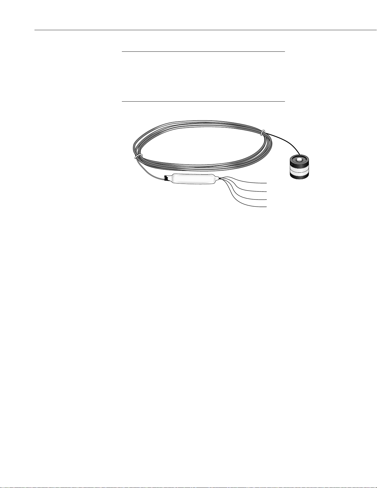
FIGURE 1-1. LI200X Pyranometer
The LI200X should be mounted such that it is never shaded by the
tripod/tower or other instrumentation. The sensor should be mounted with the
cable pointed towards the nearest magnetic pole, e.g. in the Northern
Hemisphere point the cable towards the North Pole.
Mounting height is not critical for the accuracy of the measurement. However,
pyranometers mounted at heights of 3 m or less are easier to level and clean.
To ensure accurate measurements, the LI200X should be mounted using
LI2003S base/leveling fixture. This base incorporates a bubble level and three
adjustment screws. The LI200X and base/leveling fixture are attached to a
tripod or tower using one of three mounting configurations (see Figure 2-1
through 2-3).
Tools required for installation on a tripod or tower:
Small and medium Phillips screwdrivers
5/32” Allen wrench for NU-RAIL (Figure 2-3)
1/2” open end wrench for 015ARM or CM225 (Figures 2-1, 2-2)
Tape measure
UV-resistant wire ties
Side-cut pliers
Compass
Step ladder
2
Page 7

LI200X Pyranometer
NOTE
Remove the red cap after installing the sensor. Save this cap for
shipping or storing the sensor.
LI200X Pyranometer
LI2003S
CM225 Stand
CM200 Series Crossarm
FIGURE 2-1. CM225 Pyranometer Mounting Stand
and CM202 Crossarm
FIGURE 2-2. 015 Pyranometer Mounting Arm
3
Page 8

LI200X Pyranometer
3. Wiring
FIGURE 2-3. 025 Crossarm Stand and 019ALU Crossarm
A schematic diagram of the LI200X is shown in Figure 3-1.
Connections to Campbell Scientific dataloggers are given in Table 3-1. When
Short Cut software is used to create the datalogger program, the sensor should
be wired to the channels shown in the wiring diagram created by Short Cut.
TABLE 3-1. Connections to Campbell Scientific Dataloggers
Color
Description
CR9000(X)
CR5000
CR3000
CR1000
CR800
CR850
Red Signal Differential
High
Black Signal
Reference
White Signal Ground
Clear Shield
Differential
Low
CR510
CR500
CR10(X)
Differential
High
Differential
Low
AG
G
21X
CR7
CR23X
Differential
High
Differential
Low
4
Page 9

LI200X Pyranometer
NOTE
H
RED
40.2 to 90.2 Ω
BLACK
L
AG OR GND
GND
If a 21X is used to measure the LI200X and powers a 12 VDC
sensor, the current drawn by the 12 VDC sensor may cause a
difference in ground potential between the 21X ground terminals
and the reference ground point in the datalogger. This ground
potential results in an offset on single ended measurements. This
offset can be as large as ± 60 mV. Thus, single ended
measurements should be avoided. The offset does not, however,
affect differential measurements.
WHITE
CLEAR
FIGURE 3-1. LI200X Schematic
4. Programming
This section is for users who write their own datalogger programs. A
datalogger program to measure the LI200X can be created using the Short Cut
software. You do not need to read the following section to use Short Cut.
-2mV-1
Output from the LI200X is 0.2 kWm
datalogger using the differential voltage instruction (VoltDiff in CRBasic or
Instruction 2 in Edlog). Dataloggers that use CRBasic include the CR800,
CR850, CR1000, CR3000, CR500, and CR9000(X). Dataloggers that use
Edlog include the CR510, CR10(X), and CR23X. Both CRBasic and Edlog
are included in PC400 and LoggerNet datalogger support software.
Nearby AC power lines, electric pumps, or motors can be a source of electrical
noise. If the sensor or datalogger is located in an electrically noisy
environment, the measurement should be made with the 60 or 50 Hz rejection
integration option as shown in the example programs.
Solar radiation can be reported as an average flux density (W m
flux density (MJ m
Programming examples are given for both average and daily total solar
radiation. Negative values should be set to zero before being processed.
-2
). The appropriate multipliers are listed in Table 4-1.
, which is measured by the
-2
) or daily total
5
Page 10

LI200X Pyranometer
4.1 Example Programs
TABLE 4-1. Multipliers Required for
Average Flux and Total Flux Density in Sl
and English Units
UNITS MULTIPLIER PROCESS
W m-2 200 Average
MJ m-2 t * 0.0002 Total
kJ m-2 t * 0.2 Total
cal cm-2 min-1 0.2 * (1.434) Average
cal cm-2 t * 0.2 * (0.0239) Total
t = datalogger execution interval in seconds
The following programs measure the LI200X every 10 seconds, and convert
the mV output to Wm
flux (Wm
-2
) and a daily total flux density (MJm-2). Negative values are set to
zero before being processed. Wiring for the examples is given in Table 4-2.
TABLE 4-2. Wiring for Example Programs
Color Description CR1000 CR10X
Red Signal 1H 1H
Black Signal Reference 1L 1L
White Signal Ground
Clear Shield
4.1.1 CR1000 Example Program
In the CR1000 example, a daily total flux density is found. This total flux
density is in MJ m
added to the running total.
'CR1000
'Declare Variables and Units
Public SlrW
Public SlrMJ
Units SlrW=W/m²
Units SlrMJ=MJ/m²
-2
and MJm-2. Both programs output an hourly average
-2
day-1. Negative values are set to zero before they are
AG
G
6
Page 11

LI200X Pyranometer
'Define Data Tables
DataTable(Table1,True,-1)
DataInterval(0,60,Min,10)
Average(1,SlrW,FP2,False)
EndTable
DataTable(Table2,True,-1)
DataInterval(0,1440,Min,10)
Totalize(1,SlrMJ,IEEE4,False)
EndTable
'Main Program
BeginProg
Scan(10,Sec,1,0)
'measure the LI200X
VoltDiff(SlrW,1,mV7_5,1,True,0,_60Hz,1,0) ‘use 20mV range for
‘CR5000 and CR3000
‘set negative values to zero
If SlrW<0 Then SlrW=0
‘convert mV to MJ/m2 for 10 second execution interval
SlrMJ=SlrW*0.002
‘convert mV to W/m2
SlrW=SlrW*200.0
'Call Data Tables and Store Data
CallTable(Table1)
CallTable(Table2)
NextScan
EndProg
4.1.2 CR10X Example Program
;{CR10X}
*Table 1 Program
01: 10.0000 Execution Interval (seconds)
; measure the LI200X
1: Volt (Diff) (P2)
1: 1 Reps
2: 22 7.5 mV 60 Hz Rejection Range ;use 15 mV range for the
;21X and CR7,10 mV range for CR23X.
3: 1 DIFF Channel
4: 3 Loc [ SlrW ] ; result in mV
5: 1 Multiplier
6: 0 Offset
7
Page 12

LI200X Pyranometer
; set negative values to zero
2: If (X<=>F) (P89)
1: 3 X Loc [ SlrW ]
2: 4 <
3: 0 F
4: 30 Then Do
3: Z=F x 10^n (P30)
1: 0 F
2: 0 n, Exponent of 10
3: 3 Z Loc [ SlrW ]
4: End (P95)
; convert mV to MJ/m2 for 10 second execution interval
5: Z=X*F (P37)
1: 3 X Loc [ SlrW ]
2: 0.002 F
3: 4 Loc [ SlrMJ ]
; convert mV to W/m2
6: Z=X*F (P37)
1: 3 X Loc [ SlrW ]
2: 200.0 F
3: 3 Z Loc [ SlrW ]
7: If time is (P92)
1: 0 Minutes (Seconds --) into a
2: 60 Interval (same units as above)
3: 10 Set Output Flag High (Flag 0)
8: Set Active Storage Area (P80)
1: 1 Final Storage Area 1
2: 101 Array ID
9: Real Time (P77)
1: 1220 Year,Day,Hour/Minute (midnight = 2400)
10: Average (P71)
1: 1 Reps
2: 3 Loc [ SlrW ]
11: If time is (P92)
1: 0 Minutes (Seconds --) into a
2: 1440 Interval (same units as above)
3: 10 Set Output Flag High (Flag 0)
12: Set Active Storage Area (P80)
1: 1 Final Storage Area 1
2: 102 Array ID
8
Page 13

13: Real Time (P77)
1: 1220 Year,Day,Hour/Minute (midnight = 2400)
14: Resolution (P78)
1: 1 High Resolution
15: Totalize (P72)
1: 1 Reps
2: 4 Loc [ SlrMJ ]
16: Resolution (P78)
1: 0 Low Resolution
4.2 Total Solar Radiation
If the solar radiation is totalized in units of kJ m-2, there is a possibility of
overranging the output limits. For CRBasic dataloggers, you can avoid this by
using the IEEE4 or long data format. The largest number that an Edlog
datalogger can output to final storage is 6999 in low resolution and 99999 in
high resolution.
LI200X Pyranometer
5. Maintenance
For Edlog dataloggers, if you assume that the daily total flux density is desired
-2
in kJ m
output limit will be exceeded in just under four hours. This value was found
by taking the maximum flux density the datalogger can record in low
resolution and dividing by the total hourly flux density.
39
To circumvent this limitation for Edlog dataloggers, record an average flux
(see Example 2). Then, during post processing, multiply the average flux by
the number of seconds in the output interval to arrive at a output interval flux
density. Sum the output interval totals over a day to find a daily total flux
density.
Another alternative for Edlog dataloggers is to record total flux using the high
resolution format (Instruction 78, see Datalogger manuals for details). The
disadvantage of the high resolution format is that it requires four bytes of
memory per data point, consuming twice as much memory as low resolution.
On a monthly basis the level of the pyranometer should be checked. Any dust
or debris on the sensor head should be removed. The debris can be removed
with a blast of compressed air or with a soft bristle, camel hair brush. Check
that the drain hole next to the surface of the sensor is free of debris.
and assume an irradiance of 0.5 kW m-2, the maximum low resolution
2
−
kJ m
6999
..
=
hr
kJ m s s hr
0 5 3600
()()
21 1
−− −
(1)
9
Page 14

LI200X Pyranometer
−
−
CAUTION
Handle the sensor carefully when cleaning. Be careful not
to scratch the surface of the sensor.
Recalibrate the LI200X every two years. Obtain an RMA number before
returning the LI200X to Campbell Scientific, Inc. for recalibration.
6. Calibration
LI200X pyranometers output a current that is proportional to the incoming
solar radiation. Each LI200X has a unique calibration factor. A variable shunt
resistor in the cable converts the current to the voltage measured by the
datalogger. Campbell Scientific sets the shunt resistor so that the pyranometer
outputs 5 mV kW
The resistor value is found using Ohms law. The resistance is found by
dividing the desired output voltage by the calibrated current output. For
example, a pyranometer with a calibration of 92 μA kW
resistor set to:
54.35 Ω=
7. Troubleshooting
-1 m2
.
5 0 092
mV kW m mA kW m. .
12 12
-1 m2
, will have the
Symptom: -9999 or radiation values around 0
1. Check that the sensor is wired to the Differential channel specified by the
measurement instruction.
2. Verify that the Range code is correct for the datalogger type.
3. Disconnect the sensor leads from the datalogger and use a DVM to check
the voltage between the red (+) and the black (-) wires. The voltage
should be 0 – 5 mV for 0 to 1000 Wm
-2
radiation. No voltage indicates a
problem with the photodiode, cable, or the variable shunt resistor.
Symptom: Incorrect solar radiation
1. Make sure the top surface of the sensor head is clean, and that the sensor
is properly leveled.
2. Verify that the Range code, multiplier and offset parameters are correct
for the desired engineering units and datalogger type.
10
Page 15

Appendix A. LI200S Pyranometer
A.1 LI200S Pyranometer
LI200S pyranometers have a 100 ohm shunt resistor built into the cable. They
can be directly measured by Campbell Scientific dataloggers. The input range
and multipliers vary from one pyranometer to another. See Sections A.3 and
A.4 for calculating the proper input range and multiplier.
A.1.1 Wiring
The red lead is connected to the high side (H) of a differential input channel
and the black lead to the corresponding low side (L). On the CR10 a jumper
wire is installed between the low side and analog ground (AG). The clear lead
is connected to ground (G). On the 21X the jumper wire is installed between
the low side and ground (G) and the clear lead is also connected to ground (G).
The measurement is then made with Instruction 2 (see Section 4).
A.2 Unmodified Pyranometers
Pyranometers that do not have variable or fixed shunt resistors built into the
cable can still be measured by Campbell Scientific dataloggers. This is done
by wiring in a 100 Ω shunt resistor directly onto the datalogger wiring panel.
The input range and multipliers vary from one pyranometer to another. See
Sections A.3 and A.4 for calculating the proper input range and multiplier.
A.2.1 Wiring
Signal positive is connected into the high side(H) of a differential input
channel and signal negative to the corresponding low side (L). A jumper wire
is installed between the low side (L) and analog ground (AG) on the CR10
wiring panel or ground on the 21X. A 100 Ω 1% resistor (P/N 191) is installed
on the wiring panel between the high and low sides the measurement channel.
The measurement is then made with Instruction 2 (see Section 5).
FIGURE A.2-1. Unmodified Pyranometer Wiring Schematic
A-1
Page 16

Appendix A. LI200S Pyranometer
A.3 Input Range
The following is an example of how to determine the optimum input range for
a given sensor calibration and maximum expected irradiance. This is an
example only. Your values will be different.
A.4 Multiplier
This example uses the calibration provided by LI-COR, Inc. Assume that the
sensor calibration is 87 µA kW
converted to voltage by the 100 Ω shunt resistor in the cable or on the wiring
panel. To convert the calibration from current to voltage, multiply the LI-COR
calibration by 0.1 KΩ (shunt resistor). The example calibration changes to 8.7
mV kW
A reasonable estimate of maximum of irradiance at the earth's surface is 1 kW
m
multiplying the calibration by the maximum expected irradiance. In this
example that product is 8.7 mV. Now, select the smallest input range which is
greater than the maximum expected input voltage. In this case the 25 mV slow
range for the CR10 and 15 mV slow range for the 21X are selected.
The multiplier converts the millivolt reading to engineering units. The most
common units and equations to calculate the multiplier are listed in Table
A.4-1.
-1 m2
.
-2
. Thus, an estimate of the maximum input voltage is obtained by
TABLE A.4-1. Multipliers Required for Average Flux
and Total Flux Density for SI and
English Units for a LI200S Pyranometer
-1 m2
. The pyranometer outputs current which is
UNITS MULTIPLIER PROCESS
W m-2 (1/C) * 1000 Average
MJ m-2 t * (1/C) * 0.001 Total
kJ m-2 t * (1/C) Total
cal cm-2 min-1 (1/C) * (1.4333) Average
cal cm-2 t *(1/C) * (0.02389) Total
C = (LI-COR calibration) * 0.1
t = datalogger execution interval in seconds
A-2
Page 17

Page 18

Campbell Scientific Companies
Campbell Scientific, Inc. (CSI)
815 West 1800 North
Logan, Utah 84321
UNITED STATES
www.campbellsci.com • info@campbellsci.com
Campbell Scientific Africa Pty. Ltd. (CSAf)
PO Box 2450
Somerset West 7129
SOUTH AFRICA
www.csafrica.co.za • cleroux@csafrica.co.za
Campbell Scientific Australia Pty. Ltd. (CSA)
PO Box 444
Thuringowa Central
QLD 4812 AUSTRALIA
www.campbellsci.com.au • info@campbellsci.com.au
Campbell Scientific do Brazil Ltda. (CSB)
Rua Luisa Crapsi Orsi, 15 Butantã
CEP: 005543-000 São Paulo SP BRAZIL
www.campbellsci.com.br • suporte@campbellsci.com.br
Campbell Scientific Canada Corp. (CSC)
11564 - 149th Street NW
Edmonton, Alberta T5M 1W7
CANADA
www.campbellsci.ca • dataloggers@campbellsci.ca
Campbell Scientific Centro Caribe S.A. (CSCC)
300 N Cementerio, Edificio Breller
Santo Domingo, Heredia 40305
COSTA RICA
www.campbellsci.cc • info@campbellsci.cc
Campbell Scientific Ltd. (CSL)
Campbell Park
80 Hathern Road
Shepshed, Loughborough LE12 9GX
UNITED KINGDOM
www.campbellsci.co.uk • sales@campbellsci.co.uk
Campbell Scientific Ltd. (France)
Miniparc du Verger - Bat. H
1, rue de Terre Neuve - Les Ulis
91967 COURTABOEUF CEDEX
FRANCE
www.campbellsci.fr • info@campbellsci.fr
Campbell Scientific Spain, S. L.
Avda. Pompeu Fabra 7-9, local 1
08024 Barcelona
SPAIN
www.campbellsci.es • info@campbellsci.es
Please visit www.campbellsci.com to obtain contact information for your local US or International representative.
 Loading...